

SOMFY Sonesse Ultra 50 DC RS485 Instructions Manual
Sonesse Ultra 50 DC RS485
Ref. 5123104A
Instructions
EN


Copyright © 2015 Somfy SAS. All rights reserved.
EN
Images not contractually binding
ORIGINAL GUIDE
These instructions apply to all Sonesse 50 DC irrespective of torque and speed variations.
CONTENTS
1. Prerequisite information 3
1.1 Fields of application 3
1.2 liability 4
2. Installation 4
2.1. Installation 4
2.2. Wiring 5
2.3. Commissioning 6
2.4. Tips and recommendations for
installation 7
The Sonesse ULTRA 50 DC motor has been developed for interior use.
Its ultra quiet operation ensures user comfort and well-being.
For more information, and to optimise the acoustic performance of your interior application,
please contact a Somfy adviser.
3. Use and maintenance 9
3.1. Operations 9
3.2. Tips and recommendations for use 10
4. Technical data 11
1. PREREQUISITE INFORMATION
1.1 FIELDS OF APPLICATION
The Sonesse ULTRA 50 DC motor is designed to operate interior Roller blinds applications.
The Sonesse ULTRA 50 DC motor is designed to operate multiple roller blinds simultaneously
(multi-banding), where these are interconnected by an intermediate bracket.
The Sonesse ULTRA 50 DC motor is not designed to be used with a compensating spring.
Any use outside the elds of application is prohibited, in particular:
The Sonesse ULTRA 50 DC motor is not designed for outdoor applications (e.g. outdoor vertical
blinds, roller shutters, etc.)
3
Copyright © 2015 Somfy SAS. All rights reserved.
EN
Images not contractually binding
1.2 LIABILITY
Before installing and using the motor, please read operating and installation guide carefully. In addition to following the instructions given in this guide, the instructions detailed in the
attached Safety instructions document must also be observed.
The motor must be installed by a motor and home automation professional, according
to instructions from Somfy and the regulations applicable in the country in which it is
commissioned.
It is prohibited to use the motor outside the elds of application described above. Such use,
and any failure to comply with the instructions given in this guide and in the attached Safety
instructions document, absolves Somfy from any liability and invalidates the warranty.
The installer must inform its customers of the operating and maintenance conditions for the
motor and must provide them with the instructions for use and maintenance, and the attached
Safety instructions document, after installing the motor. Any After-Sales Service operation on
the motor must be performed by a motor and home automation professional.
If in doubt when installing the motor, or to obtain additional information, contact a Somfy adviser
or go to the website www.somfy.com.
Safety warning!
Caution!
Information
2. INSTALLATION
Instructions which must be followed by the motor and home automation professional
installing the motor.
Never drop, knock, drill or submerge the motor.
Install a separate control point for each motor.
To optimize ultra quiet operation, the mechanical plays between motor, accessories, tube
and end of tube must be decreased to the maximum.
2.1. INSTALLATION
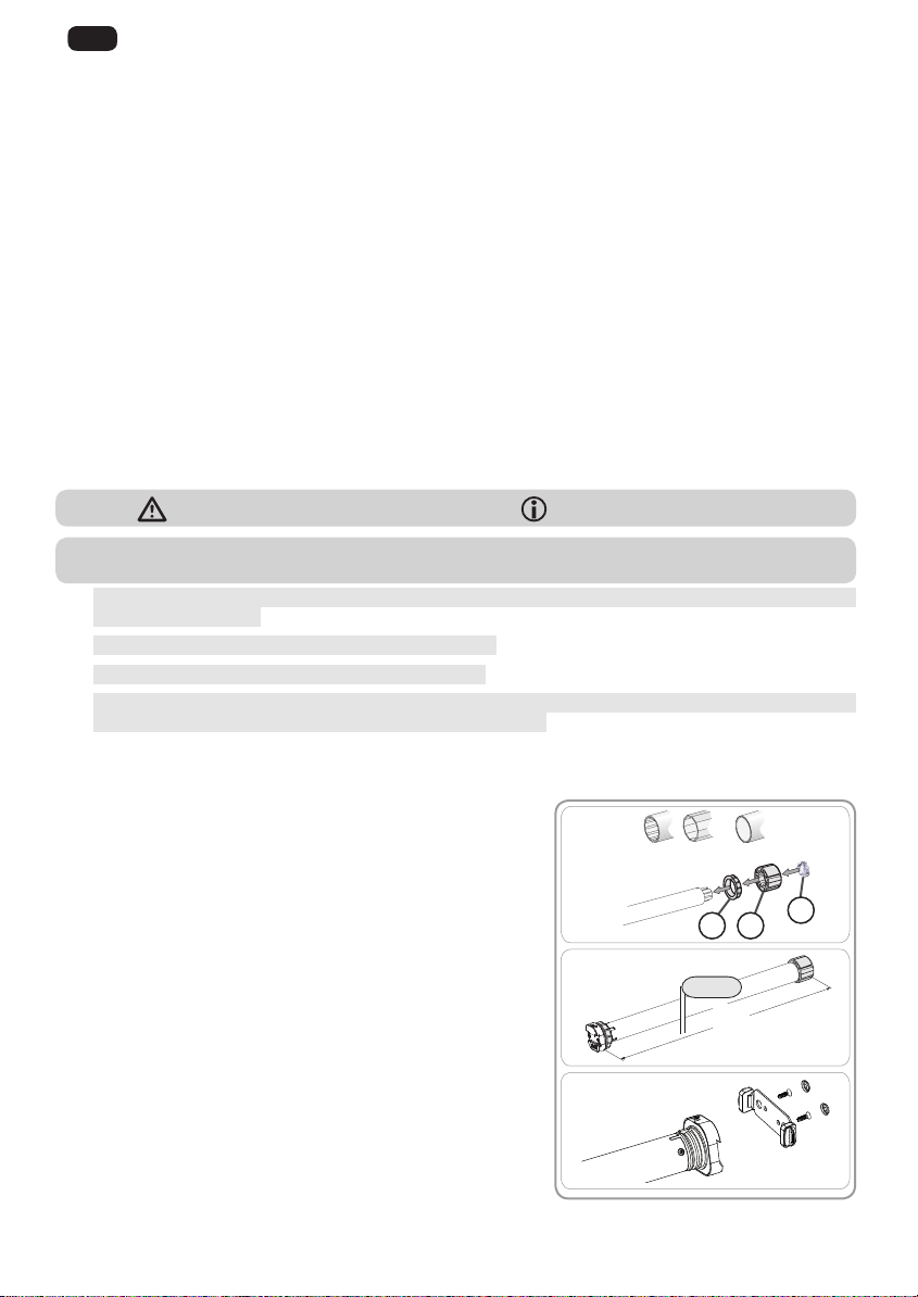
2.1.1. Preparing the motor
Check that the inner diameter of the tube greater than
47mm.
1) Fit the accessories required to integrate the motor in the
roller tube:
• Fit the crown a, the motor wheel b and the stop wheel c
on the motor.
The stop wheel must be screwed with a torque ranging
between 1.5 and 1.8 Nm.
2) Measure the length (L1) between the inner edge of the
motor head and the edge of the motor wheel.
3) Screw the bracket interface on the motor head.
1)
Ø > 47 mm
ba
2)
L1 = …
L1
3)
c
4

Copyright © 2015 Somfy SAS. All rights reserved.
EN
Images not contractually binding
2.1.2. Tube preparation
V+
V-
+
-
G
1) Cut the roller tube to the required length, depending on
the motorised product.
2) Deburr the roller tube and remove the swarf.
1) 2)
2.1.3. Motor/tube assembly
1) Slide the motor into the roller tube.
2) The motor wheel must be locked in place to prevent
movement inside the roller tube:
• This can be done either by xing the roller tube to the
motor wheel using 4 x Ø 5 mm self-tapping screws,
or by using 4 x Ø 4.8 mm steel pop rivets placed 5
mm to 15 mm from the outer edge of the motor wheel,
regardless of the roller tube.
The screws or pop rivets must only be attached to the
motor wheel and not to the motor.
3) Slide the end cap into the roller tube and locked it if
necessary.
2.1.4. Installing the motor/tube assembly
The motorised product must not be compressed
between the brackets
1) Install and x the motor/tube assembly onto the end
bracket f and onto the motor bracket g:
Ensure that the motor/tube assembly is secured onto
the end bracket. This operation prevents the motor/
tube assembly from coming out of the end bracket
mounting when the roller blind reaches the lower end
limit position.
2) Clip the stop ring h in place.
1)
2)
3)
1)
g
2)
h
15 mm
L1
5 mm
20 mm
f
2.2. WIRING
Cables which pass through a metal wall must be protected and isolated using a grommet
or sleeve.
Attach cables to prevent any contact with moving parts.
Leave the motor power supply cable accessible: it must be possible to replace it easily.
- Switch off the power supply (compatible power supply, see p9).
- Connect the cable to the motor head.
Power Data
5
 Loading...