

SOMFY Sonesse 30 DCT Installation Instructions Manual
www.somfy.com
Sonesse® 30 DCT
Installation instructions
Ref :5051080A

1Copyright © 2008 Somfy SAS. All rights reserved - V0 - 11/2008
SAFETY
• This Somfy product must be installed by a professional motorization and home automation installer,
for whom these instructions are intended.
• Before installation, check that this product is compatible with the associated equipment and acces-
sories.
• These instructions describe how to install, commission and use this product.
• Moreover, the installer must comply with current standards and legislation in the country in which
the product is being installed, and inform his customers of the operating and maintenance conditions
for the product.
• Any use outside the sphere of application specied by Somfy is not approved. Such use, or any
failure to comply with the instructions given herein will invalidate the warranty, and Somfy refuses to
accept liability.
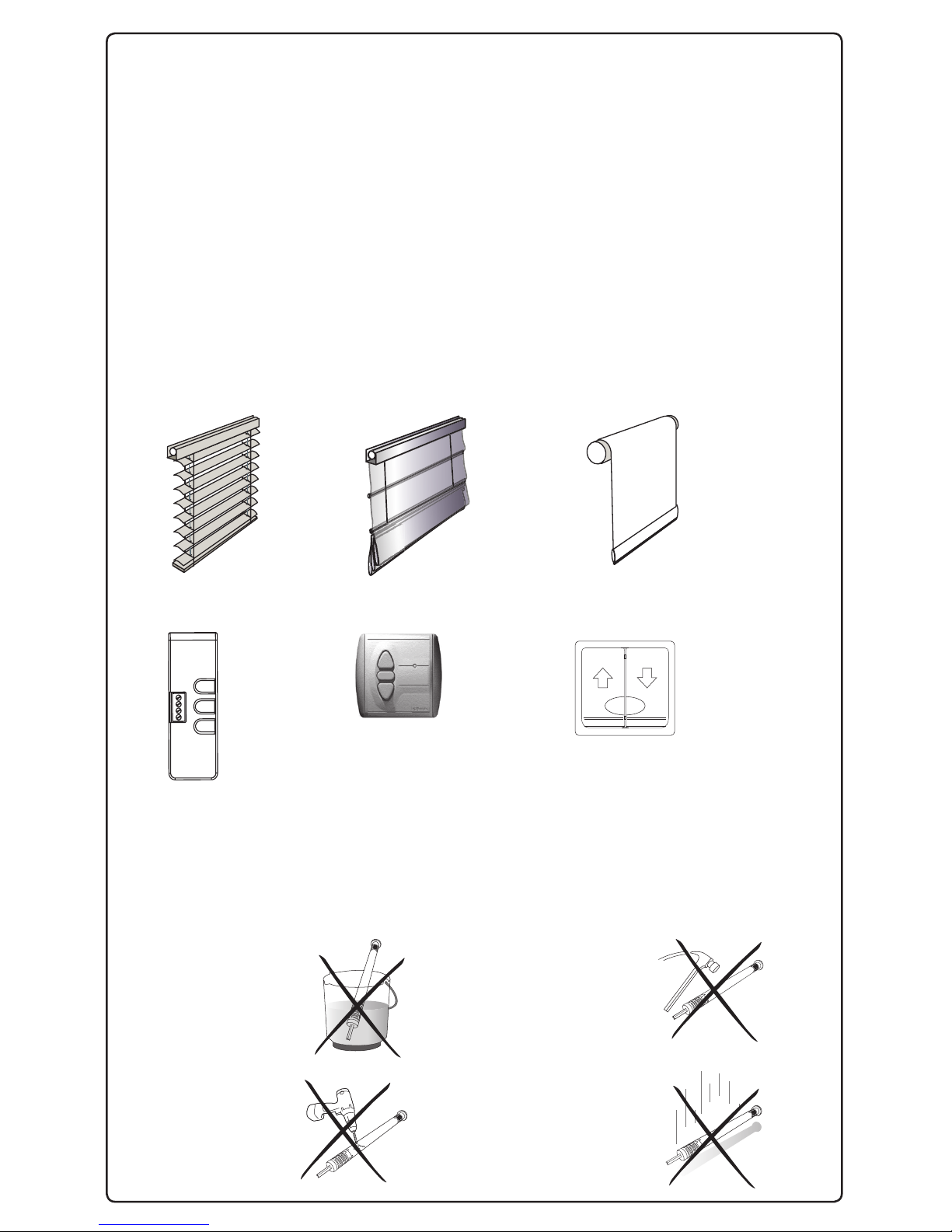
COMPATIBLE BLINDS
Venetian blinds Roman shades Roller blinds
COMPATIBLE CONTROL
GENERAL SAFETY INSTRUCTION
The safety instructions that must be observed, besides the usual rules, are
explained in these instructions and in the attached «Safety Instructions» document.
Never immerse the
motor in liquid!
Never drill holes in the
motor!
Avoid impacts!
Do not drop it!
ST OP
Setting Tool Centralis IB Wall Switch
2 Copyright © 2008 Somfy SAS. All rights reserved - V0 - 11/2008
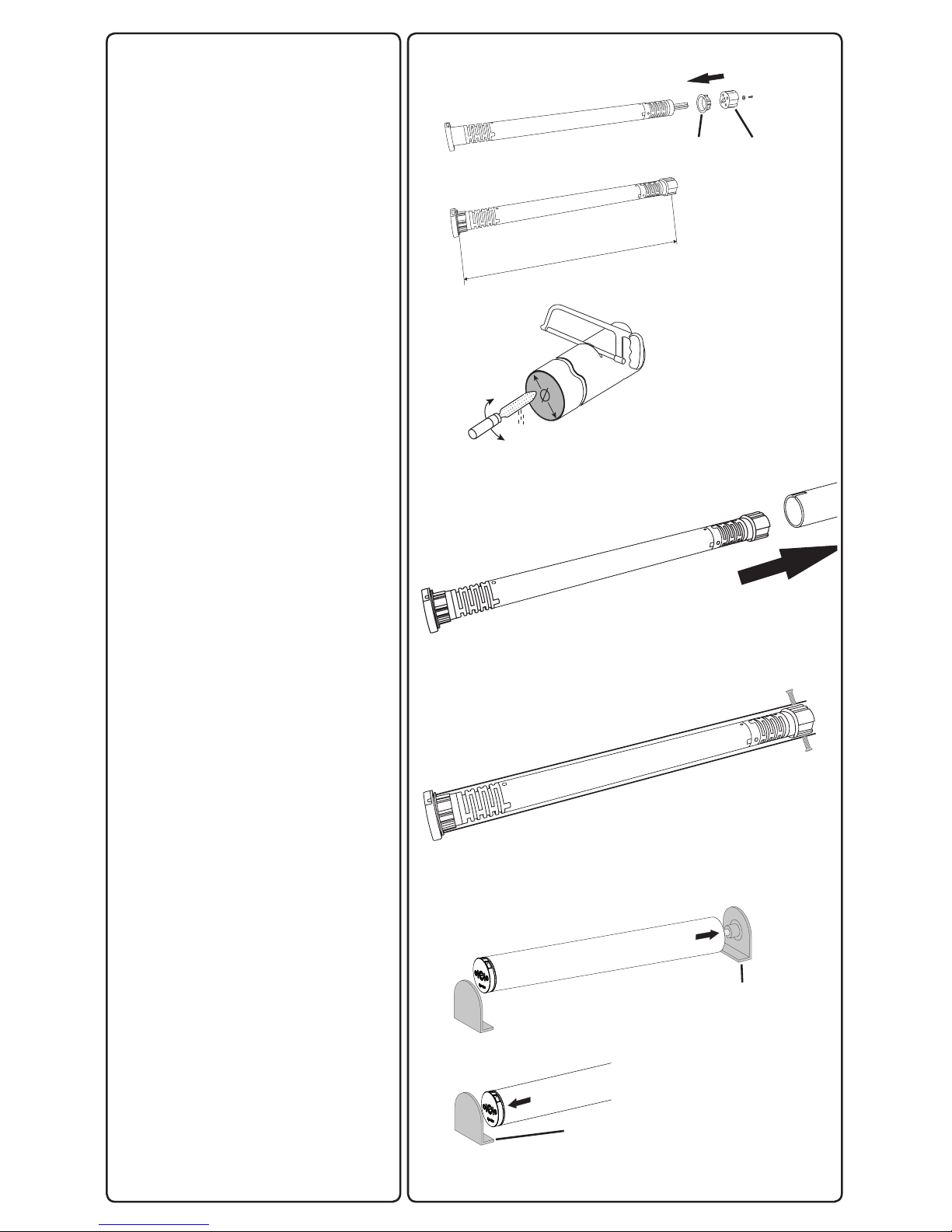
INSTALLATION
Motor preparation
1) Fit the crown (a) and drive wheel (b)
to the motor.
2) Measure the length (L) between
the middle of the drive wheel and the
head end.
Tube preparation
Cut the tube to the required length.
Deburr the tube and remove the
debris.
Motor/tube assembly
1) Slide the motor into the tube.
2) Fix the tube to the motor with selftapping screws or steel pop rivets
depending on the dimension (L).
Mounting the motorized tube on the
brackets
If necessary, screw the bracket interface on the motor head.
Mount the motorized tube on the end
bracket (C ).
Mount the motorized tube on the
motor bracket (D).
L
1
2
a
b
1
2
c
d
3Copyright © 2008 Somfy SAS. All rights reserved - V0 - 11/2008
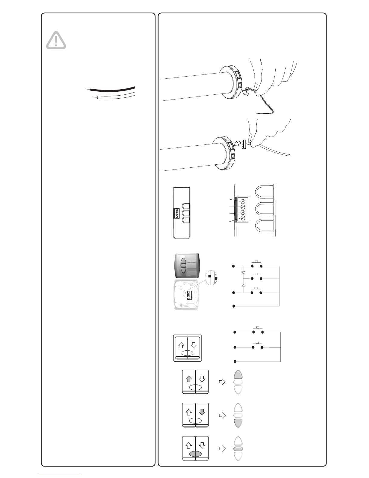
Wiring
Sonesse® 30 DCT is Dry
contact motor.It can’t be
controlled with power going
through the setting tool cable.
1) Connect the power cable to the
motor.
2 ) Connect the setting tool cable to
the motor.
3) Control wiring
Setting Tool
1 UP (White/Blue)
2 STOP (Blue)
3 DOWN (White/Orange)
4 GND (Orange)
Centralis IB
1 UP or DOWN (White/Blue or White/
Orange)
2 UP or DOWN (White/Blue or White/
Orange)
3 GND (Orange)
Wall Switch
1 UP or DOWN (White/Blue or White/
Orange)
2 UP or DOWN (White/Blue or White/
Orange)
3 GND (Orange)
4) Correspondence
+
C
+
-
-
1
2
C
ST OP
1
2
3
1
2
3
4
+
-
1
2
ST OP
ST OP
ST OP
3
4
 Loading...