

SOMFY CD 1 x 4 P6, CD 1 x 4 P8, CD 1 X 4 P Series Installation Manual
CD 1 X 4 P Four motors control unit
The CD 1 x 4 P enables the individual control of 4 x 230 V AC motors. As the CD 1 x 4 P can be
used as local and master control, it is suitable for large and small installations. An additional group
control is no longer necessary with the CD 1 x 4 P.
The CD 1 x 4 P is suitable for roller shutters, awnings, as for exterior and interior Venetian blinds.
The slat rotation is adjustable.
General control is activated by IB compatible control units (such as e.g. a timer control, solar
and wind control or façade control) and transferred to all CD 1 x 4 P via the IB low voltage BUS
line.The 4 motors can be operated locally in one group by a local switch. Several push buttons and units can be connected
in parallel.
Tw o previously recorded intermediate positions can be called-up via an optional button (“IP key”). By connecting a switch, it is
possible to disconnect the automatic mode. All the safety commands, which are activated by the BUS line, have priority even
when the automatic mode is disconnected. The BUS line is powered directly by the CD 1 x 4 P.
The CD 1 x 4 P can be installed whether surface-mounted, in false floors, partition walls or false ceilings, or in an electrical
cabinet with a special DIN rail adapter.
ATTENTION : observe precaution for handling electrostatic discharge sensitive devices.
The printed circuit board is packed in an anti-static protective covering upon delivery.
INSTALLATION
guide
Ref. GMD021010
1
Installation
Assembly, testing, commissioning and trouble-shooting of the unit may only be carried out by a qualified electrician (respect the local
electrical standard). Disconnect all the connection wires which are to be fitted. Take the necessary safety measures to prevent unintentional reconnection.
Proper functioning can only be guaranteed by expert installation and sufficient power supply.
1.1 Assembly / Wiring
CD 1 x 4 P6 for the DIN rail
When fitting the CD 1 x 4 P6 board on 35 mm DIN rail, two DIN rail adapters are used.
Put the board on the adapter and then clip the adapter onto the DIN rail.
When installing the unit in an electrical cabinet, please observe that a protection must be used to prevent direct access to the electrically conductive components.
CD 1 x 4 P8 for surface-mounting
The board is screwed into a IP 54 box and can be installed in false ceilings, partition walls or false floors in damp rooms.
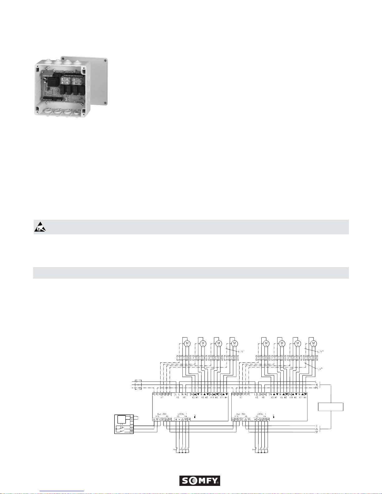
Motor 1 Motor 2
Mains
230V 50Hz
Live (L)
Neutral (N)
Ground (PE)
Jonction Box
Dry contacts control system :
Soliris IB
Chronis IB
Centralis IB
Outputs MCII
Local group control
motors 1 to 4
Local group control
motors 5 to 8
IB Bus line
to other CD 1x4 P
motor conrol units
Motor 3
SW1
ON
UP
AUTO ON/OFF
DOWN
IP
+
UP
AUTO ON/OFF
DOWN
IP
+
ON
Control
system
Mains
SW1
Motor 4 Motor 5
CD 1x4 PCD 1x4 P
Motor 6 Motor 7 Motor 8
Connection wires:
max. 2.5 mm2 rigid wires or 1.5 mm2
stranded wires
PE (x6): Earth (all PEs are bridged)
L/N (x2) :Mains (both L and N are bridged)
M1 to M4: N/▲/▼ (x4)
Motors 1 to 4
Local 1: A /+/▲/▼/IP
on/off switch for all 4 motors (optional)
local switch (up/down/stop) for all 4 motors
local swirch for the intermediate position
(“IP key”) for all 4 motors (optional)
Bus 20 V: ▲/▼/COM (x2)
IB Bus line (coming and going)
SW1:
Dipswitch for selecting roller
shutters/awnings (ON)
or Venetian blinds (OFF) for all 4 motors.

2.1
Selecting between roller shutters/awnings and Venetian blinds
The selection is carried out via the dipswitch SW1 (see wiring diagram) :
- switch power supply off
- set dipswitch to ON ➜ roller shutters/awnings mode
- set dipswitch to OFF ➜ Venetian blinds mode
- turn power supply back on
When delivered, the dipswitch is set to Venetian blinds.
Warning : The CD 1 x 4P does not allow mixed installation.
2.2
Selecting between automatic mode and local mode (Automatic mode on/off)
Selecting between automatic mode and local mode requires a switch which has to be connected externally (see wiring diagram). In automatic mode, the general commands are automatically activated by IB compatible control units (such as a timer control, sun control, wind
control, general or façade control). In local mode, commands are activated by locally connected switches :
- connect the switch (see wiring diagram).
- switch open ➜ automatic mode is activated.
All general and local commands are carried out. Local operation is not possible while general prioritary commands are activated (e.g. by
a wind control).
- switch closed ➜ automatic mode is desactivated.
General commands are not carried out if they do not have priority. Only local commands are carried out in this case. If the general command has however higher priority (e.g. activated by a wind control), a command is given to the blind even though the automatic switch is
disconnected (safety function).
Instead of connecting the switch (depending on the function required) it is possible to leave the connection open or bridge it.
Possibility to select two tilting functions : European or US type.
"European" tilting mode:
- Press briefly less than 0,8s ➜ the Venetian blind will be activated during the time of pressing (tilting of the slats).
- Press and hold more than 0,8s ➜the Venetian blind will be activated during 3 minutes (Up or Down control).
"US" tilting mode:
- Press briefly less than 0,2s or continuous control longer than 6s ➜the Venetian blind will be activated during 3 minutes (Up or Down control).
- Press and hold more than 0,2s and shorter than 6s ➜the Venetian blind will be activated during the time of pressing (tilting of the slats).
The product is initially configured in European tilting mode. Only one type of tilting mode can be set for all motors, a mixed mode is not
possible.
To change the tilting mode:
- Disconnect the mains supply of the motor control unit (cut off shortly the mains supply and turn it on again).
- During the next 30 seconds, press the connected “IP key” (see wiring diagram) for 5 seconds or, if no “IP key” is connected, bridge the
input of the "IP" connection to the "+" terminal for 5 seconds.
2.3
Operating ergonomics of the slat rotation
Local operation of the 4 motors is carried out via the local switch connected to the unit.
Several local switches can be connected in parallel.
Switches supplied by switch manufacturers as well as the SOMFY Centralis IB switch can ensure local operation.
- Connect the local switch (see wiring diagram)
- Press the corresponding key to move the motors UP or DOWN.
- Stop the 4 motors:
by pressing simultaneously the UP and DOWN keys.
or
by pressing the reverse direction
or by pressing the same button again
or
by pressing the “IP key”, if it is connected.
2
Settings
3
Local operation
 Loading...