

SOMFY Axovia multi Installation Instructions Manual
Wing gate hydraulic actuators – Installation instructions
multi
Mechanical assembly
5012073
2
Table of contents
1
Safety instructions
Standard model
6
Assembly constraints
Specific / standard kits
2
Mechanical kit composition
3
Technical characteristics
4
Pre-assembly checks
5
Assembly process
1
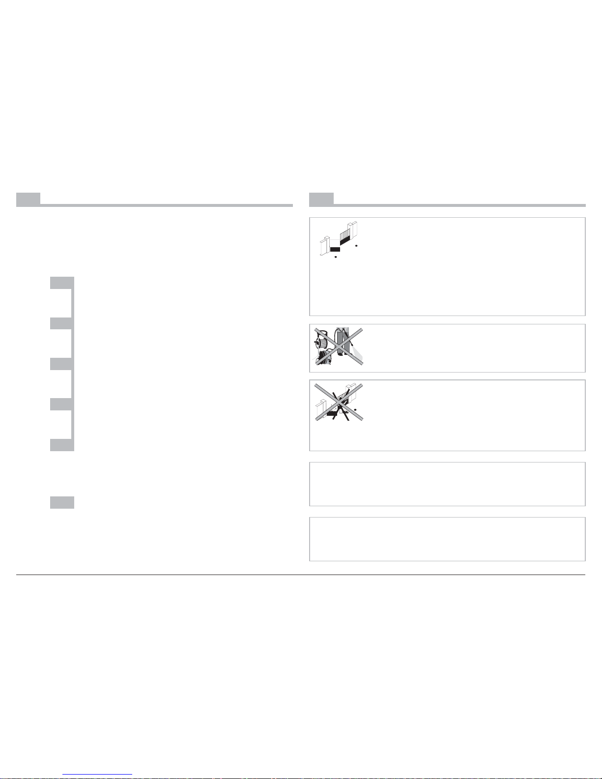
Safety instructions
Make sure that the hazardous areas (crushing, shearing,
wedging) between the driven part and the surrounding fixed
parts due to the opening movement of the driven part are
avoided.
Regularly inspect the state of the gate. Those gates in poor
condition should be repaired, reinforced or even changed prior
to installation. Regularly check that the screws and fastenings of
the Axovia's various components are securely tightened.
Maintain a clearance area of 500 mm at the back of each wing
when the gate is completely open.
Do not clean your Axovia with a high-pressure water flow rate
cleaning appliance.
Disconnect your Axovia from any electricity source while carrying
out cleaning operations or other maintenance operations if the
appliance is controlled automatically.
Never allow children to play near moving gates.
Never allow children to play with fixed control devices.
Always place the remote control devices out of reach of children.
Always keep a watch over your gate while it is moving.
Never handle your Axovia while it is energized or with the
battery.
Wear protective goggles during the drilling phases.
3
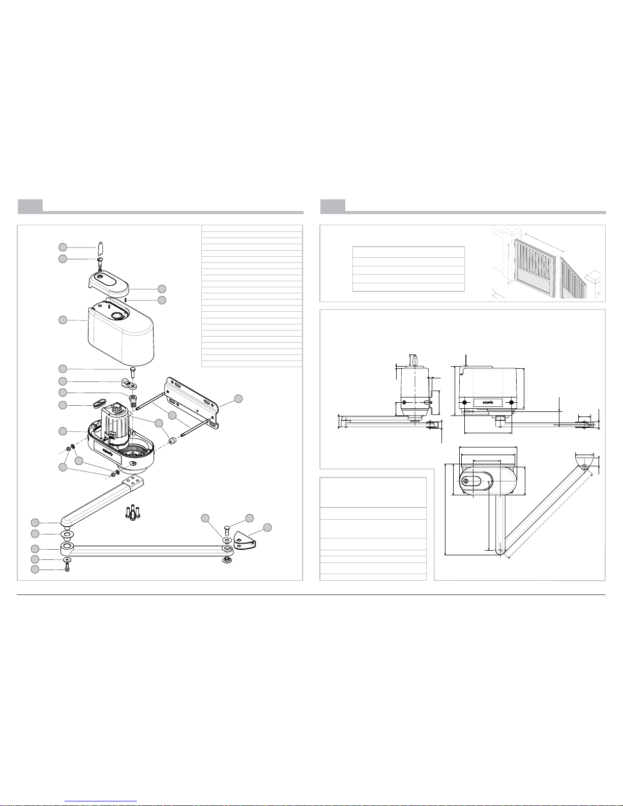
2
Mechanical kit composition
4
3
11
12
13
2221
23
2
1
5
9
6
7
8
10
16
17
18
19
20
15
14
1 Cover key x2
2 Cover screw x2
3 Guard cover x2
4 Motor cover screw x4
5 Motor cover x2
6 Stop screws + arm x10
7 Opening stop x2
8 Closing stop x2
9 Grommet x2
10 Motor x2
11 Motor/pillar fastening plate x2
12 Fastening stud x4
13 Spacer tube x4
14 Flat washer x4
15 Nut x4
16 Motor arm x2
17 Motor arm / gate arm bush x2
18 Gate arm x2
19 Washer x2
20 Motor arm / gate arm screw x2
21 Gate arm bush x4
22 Long clevis pin for gate arm x2
23 Gate clevis x2
3
Technical characteristics
Maximum dimensions of a gate
H max. height 2 m
L max. width 2 m 50
P max. weight 300 Kg
S max. full surface 4 m
2
H
L
P
Scope
146
360
142
16
44
95
65
620
279
300
245
162
211
258
125
70,5
30,5
36,01
10,5
60
68,5
54,5
474
General overall dimensions (mm)
Table of
characteristics
Frequency of
manœuvres
40 cycles/day
Automatic obstacle
detector
Complies with the NF EN
60335-2-103 standard
with AX24 cabinet
Operating temperature -15˚C to +55˚C
Thermal protection
Yes by means of the AX24
Protection index IP 54
Motor power supply
outlets
24 VDC
Power per motor 130 W
4
4
Pre-assembly checks
When one of the motor support plate
fastening holes is either in empty
space or near the angle of the pillar,
it is absolutely essential to add a
reinforcement bracket (not
supplied).
For an opening > 90°, the
dimension of the pillar should
be 40 cm; otherwise, you MUST use
a bracket.
Pillar reinforcement bracket
If the gate does not have any wings,
provide for metal backing plates
(e.g. 40x40 mm and 4 mm thick) to
fasten the wing clevis.
For a large wing ( > 2 m ) or in
a windy region, SOMFY
recommends installation of an
electric lock.
Wing brace
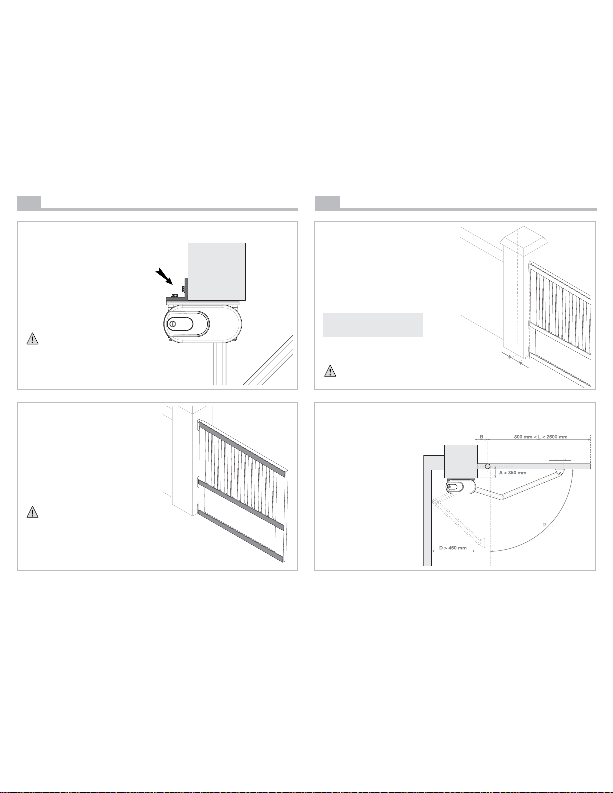
5
Assembly process
The AM vertical axis gives the
position of the motor/pillar
fastening plate.
B is the distance between the
gudgeon and the AM axis.
B depends on the a opening angle
of the wing:
If
αα
≤ 90˚ B = 70 mm min
If
αα
> 90˚ B = 150 mm
Mark out the AM axis.
Check that the open wing does
not knock against the motor.
B
AM
Locating axis markout
To be on the safe side, check
distance D: distance
between the AM axis and
the first obstacle on the side
opposite the wing (quoin)
D ≥ 450 mm.
Distance L should be
beween 800 mm and
2500 mm.
B
A < 350 mm
65
D > 450 mm
800 mm < L < 2500 mm
Required clearance
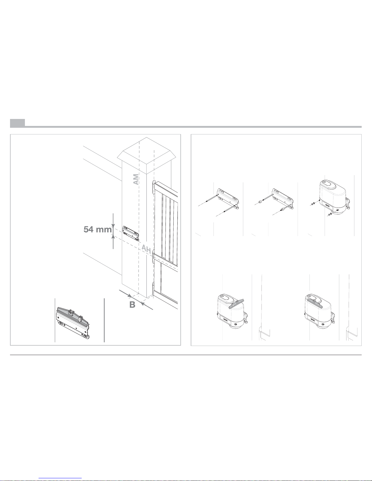
5
5
Assembly process
Mark out a horizontal axis
(AH) in the middle of the
brace, perpendicular to the
wing's axis of rotation.
Extend this axis onto the
pillar as far as the
intersection with AM.
Gate with no brace: if the
gate has no no brace, place
the motors at approx. 1/3 of
the height of the wings
starting from the ground.
In addition, you will be
required to provide for
brackets for fastening the
clevises (see page 4).
Place the motor/pillar
fastening plate at a distance
of 54 mm above AH.
Mark out the drilling points
and drill them: to improve
adjustment, use the round
holes to make your mark,
drill, then turn the fastening
plate over and fix using the
oblong holes.
Check that the
plate is in a
perfectly
horizontal
position.
Mounting the fastening plate
1.
Mount the fastening
gudgeons on the pillar
fastening plate, screw
them as far as the
thread will go.
2. Slide the spacers
onto the fastening
gudgeons.
3. Position and
fasten the motor.
Check that it is in a perfectly horizontal position:
Mounting the motor on the plate
 Loading...