

SOMFY axovia 400C Installaton Manual
Ref. 1 215 036 - V4
G
G
Installation guide
E
E
Guia de instalacion
O
O
Montagehandleiding
F
F
Notice d’installation
400 C
Ref. 1 216 005 - V4
F Sommaire G Contents O Inhoudsopgave E Indice
1 Consignes de sécurité 1 Safety recommendations 1 De veiligheidsinstructies 1 Las consignas de seguridad
2 Composition du Kit 2 Composition of kit 2 Samenstelling van de kit 2 Composición del kit
3 Description du boîtier électronique 3 Electronic control box description 3 Beschrijving elektronische besturingskast 3 Descripción de la unidad electrónica
4 Processus de montage 4 Assembly process 4 Montageproces 4 Proceso de montaje
5 Branchements 5 Connecting 5 Aansluitingen 5 Conexiones
6 Montage de la crémaillère 6 assembling the rack 6 Montage van de tussenrail 6 Montaje de la cremallera
7 Processus de réglage 7 Adjustment process 7 Afstellingsprocedure 7 Proceso de ajuste
8 Mémorisation des télécommandes 8 Memorising remote control 8 Memorisatieproces 8 Memorización del emisor
9 Phase d’auto-apprentissage 9 Automatic learning process 9 Leerproces 9 Fase autoaprendizaje
10 Fonctionnement 10 Operation 10 Werkingsprocedure 10 Proceso de funcionamento
11 Accessoires SOMFY
11 SOMFY
Accessories 11 SOMFY accessoires 11 Accesorios SOMFY
12 Caractéristiques techniques 12 Technical data 12 Technische gegevens 12 Caracteristicas
1
F
F
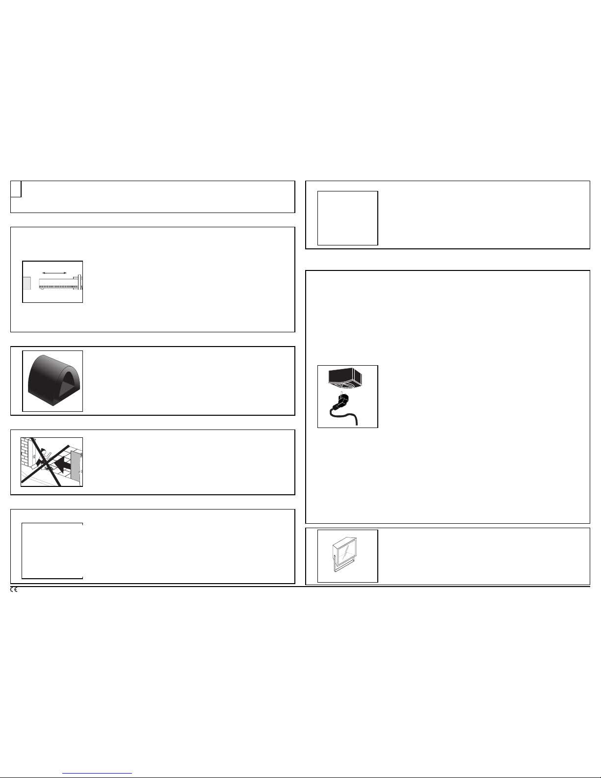
Vérifier régulièrement l’état du portail. Les portails en mauvais état doivent être
r
éparés, renforcés, voir changés avant l’installation.Vérifier régulièrement le bon
serrage des vis et des fixations des différents éléments de l’Axovia.
G
G
C
heck the condition of the gate regularly.Gates in bad condition must be repaired,
reinforced or changed before you install your Axovia.Motorising a gate in poor
condition can cause the malfunctioning of the Axovia as well as premature wear of
t
he gate.
O
O
Controleer regelmatig de staat van het schuifhek. Schuifhekken in slechte staat
dienen gerepareerd, verstevigd of vervangen te worden alvorens uw Axovia te
installeren. Daar het mechaniseren van een hek in slechte staat kan leiden tot een
onjuiste werking van de Axovia alsmede een voortijdige slijtage van het schuifhek.
E
E
Controlar regularmente el estado del portón. Los portones en mal estado deben ser
reparados y reforzados, incluso, si resulta necesario, debe cambiárseles antes de la
instalación del Axovia.
F
F
Le portail doit être arrêté par des butées fixées solidement au sol afin que sa course
soit délimitée.
G
G
Stopping devices fixed firmly to define its movement must stop the gate.
O
O
Het schuifhek dient tegengehouden te worden door stevig in de grond bevestigde
aanslagen opdat het schuiftraject begrensd wordt.
E
E
El portón debe ser detenido por topes fijados sólidamente en el suelo a fin de
delimitar su recorrido.
F
F
Ne jamais laisser jouer les enfants à proximité du portail en mouvement.
G
G
Never allow children to play near the moving gate and prevent people from passing
during the opening and closing sequences.
O
O
Laat kinderen nooit in de directe omgeving van het bewegende schuifhek spelen en
vermijd elke doorgang van personen tijdens het openen of sluiten van de deur.
E
E
No dejar nunca que los niños jueguen en la proximidad del portón en movimiento,
evitar el pasaje de personas en el momento que se abre o se cierra.
F
F
Ne jamais intervenir sur votre Axovia sous tension ou avec la batterie.
G
G
Ne
v
er work on your axovia when it is live or connected to the battery.
O
O
V
oer geen werkzaamheden uit aan uw Axovia indien deze op het lichtnet of de
accu is aangesloten.
E
E
No intervenir nunca en el sistema axovia cuando está conectado al sector o a la
batería.
F
F
P
orter des lunettes lors des phases de perçage.
G
G
Wear safety goggles when drilling.
O
O
D
raag een veiligheidsbril tijdens de boorwerkzaamheden.
E
E
U
sar anteojos de protección en la etapa del agujereado.
F
F
Pour fonctionner, l’Axovia doit être alimenté sous 230V - 50 Hz. La ligne électrique
doit être :
- exclusivement réservée à l’Axovia,
- d’une section minimale de 2,5 mm
2
,
- dotée d’une protection (fusible ou disjoncteur calibre 16A) et d’un dispositif différentiel
(30mA)
- installée selon les normes de sécurité électrique en vigueur.
Il est conseillé de munir l’installation d’un parafoudre (conforme à la norme NF
C 61740, tension résiduelle maxi 2kV).
G
G
To operate correctly, the axovia must be powered with 230 V 50 Hz.The electrical
lead must be:
- Reserved exclusively for the axovia,
- Of a minimum section of 2.5 mm_
- Properly protected (fuse or circuit breaker rated at 16 A) with a differential device
(30 mA),
- Installed according to the current electric safety standards.
It is advisable to provide the installation with a lightning arrestor (conforming
to standard NF C 61740, (maximum residual voltage 2 kV).
O
O
De Axovia dient, om te kunnen werken, aangesloten te worden op een netvoeding
van 230V- 50Hz.De elektrische leiding dient:
- Uitsluitend voor de Axovia aangewend te worden,
- Een minimale doorsnede van 2,5 mm
2
te hebben,
- Voorzien te zijn van een bescherming (zekering waarde 16A)
en een aardlekschakelaar (30mA),
- Volgens de van kracht zijnde veiligheidsnormen voor elektriciteit geïnstalleerd
te worden.
Het wordt aanbevolen de installatie te voorzien van een bliksemafleider
(overeenkomstig aan de norm NF C 61740, maximale restspanning 2kV).
E
E
Para funcionar, el axovia debe estar alimentado eléctricamente por 230V –50Hz.
La línea eléctrica debe:
- estar exclusivamente reservada al exovia
- tener una sección mínima de 2,5mm_
- estar provista de una protección (fusible o disyuntor calibre 16A) y de un
dispositivo diferencial (30mA)
- debe ser instalado según las normas léctricas de seguridad vigentes.
Se aconseja dotar a la instalación de un pararrayos (conforme a la norma
NF C 61740, tensión residual máxima 2kV)
FF
Tout éclairage alimenté en 230V raccordé sur la sortie “éclairage de zone” doit être
raccordé à la terre ou être du type double isolation.
GG
If lighting supplied with 230 V is connected to the "area lighting" output, it must be
connected to g
round or be doub
ly insulated.
OO
Elke verlichting van 230 V aangesloten op de uitgang “Zoneverlichting” dient voorzien
te zijn v
an een aarding of een dubbele isolatie.
E
E
Toda iluminación alimentada en 230V conectada en " iluminación de zona " debe
estar conectada a tierra o debe ser del tipo de aislamiento doble.
F Consignes de sécurité G Safety recommendations
O De veiligheidsinstructies E Las consignas de seguridad
1
c
I
2
Ref: 1215036
Ref: 1780607
Ref: 1216005
&
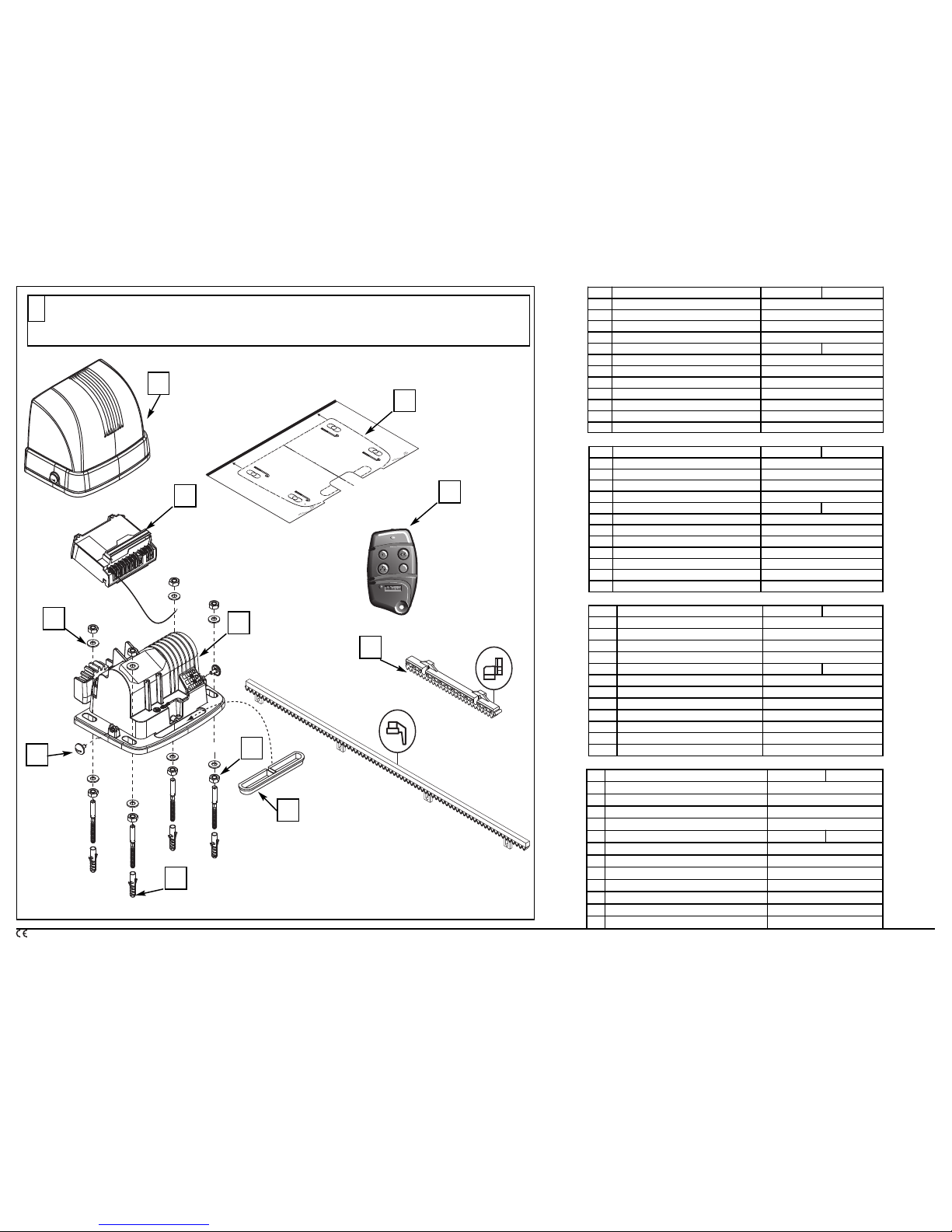
F Composition du Kit G Composition of kit
O Samenstelling van de kit E Composición del kit
2
Rep: Désignation Ref: 1 215 036 Ref: 1 216 005
1 Bloc motoréducteur 1
2 B
oîtier électronique
1
3 C
apot
1
4 Keytis 4 RTS 2
5 Crémaillère 12 x 33,7cm 0
6 Goujons 4
7 R
ondelles
8
8 E
crous
1
2
9 V
is capot
2
10G
abarit de pose
1
11 Passe fil 1
10
4
3
2
8
7
9
1
5
6
F
F
F
F
G
G
G
G
O
O
O
O
E
E
E
E
Item: Description Ref: 1 215 036 Ref: 1 216 005
1 Motor reduction unit 1
2 Electronic control box 1
3 Cover 1
4 Keytis 4 RTS 2
5 Rack 12 x 33,7cm 0
6 Fixed brackets/studs 4
7 Washers 8
8 Nuts 12
9 Cover screw 2
10 Installation template for fixing 1
11 Grommet 1
Posnr: Benaming Ref: 1 215 036 Ref: 1 216 005
1 Motorblok 1
2 Elektronisch besturingskastje 1
3 Kap 1
4 Keytis 4 RTS 2
5 Tandheugel/tandlat 12 x 33,7cm 0
6 Gebogen draadeinden / pennen 4
7 Ringen 8
8 Moeren 12
9 Schroeven voor de kap 2
10 Tekenmal voor plaasting 1
11 Doorvoertule 1
Ref: Descriptión Ref: 1 215 036 Ref: 1 216 005
1 Bloque motoreductor 1
2 Caja electrónica de mandos 1
3 Tapa 1
4 Keytis 4 RTS 2
5 Cremallera 12 x 33,7cm 0
6 Pata de empotramiento / Pernos de empotramiento 4
7 Arandelas 8
8 Tuercas 12
9 T
or
nillos tapa
2
10 Plantilla de colocación para empotramiento 1
11 Aislador pasacab
le
1
11
3
ON/OFF
AUTO
PROG
1.5 mm
2
1 mm
2
0.75 mm
2
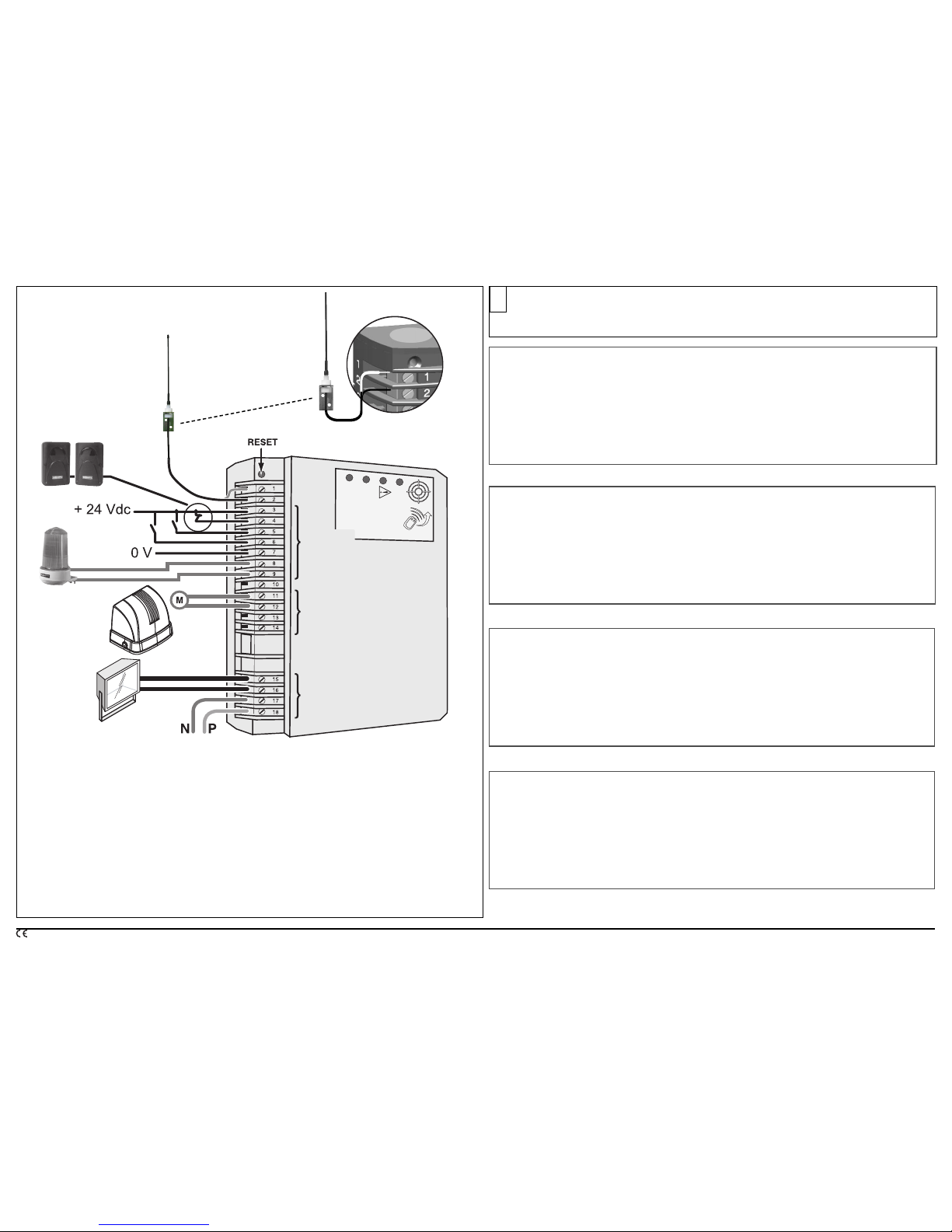
F Description du boîtier électronique G Electronic control box description
O Beschrijving elektronische besturingskast E Descripción de la unidad electrónica
3
F
1+ 2 Antenne
3 + 4 Jeu de cellules
3
+ 5 Commande pour l’ouverture totale
3 + 6 Commande pour l’ouverture piétonne
3 + 7 Sortie permettant d’alimenter les accessoires (24Vdc / 12Vac)
8
+ 9 Feu orange (sortie clignotante 24V 15 W maxi)
8 + 10 Gâche électrique selon cas spécifique.
11 + 12
Moteur 1
(24V)
13 + 14
Non Utilisé
15 + 16 Eclairage de zone (500W maxi en 230V)
17 + 18 Cable d’alimentation secteur 230V
G
1+ 2 Antenna
3 + 4 Input for Photocell contacts
3 + 5 Control for total opening
3 + 6 Control for pedestrian opening
3 + 7 Output powering the accessories (24Vdc / 12Vac)
8 + 9 Flashing output for one orange light (24V - 15W)
8 + 10 Electric strike plate according to specific case
11 + 12
Motor 1
(24V)
13 + 14
NOT USED
15 + 16 Area lighting output (500W maximum at 230V)
17 + 18 Power supply cable 230V
O
1+ 2 Antenne
3 + 4 Ingang voor foto-elektrische cellen
3 + 5 Bediening voor totale opening
3 + 6 Bediening voor voetgangersopening
3 + 7 Uitgang voeding voor accessoires (24 Vdc / 12 Vac)
8 + 9 Uitgang oranje waarschuwingslicht (24 V – 15 W)
8 + 10 elektrische (centrale) vergrendelingsplaat afhankelijk van specifiek geval
11 + 12 Motor 1 (24V)
13 + 14
NIET IN GEBRUIK
15 + 16 Uitgang verlichting (maximaal 500 W en 230 V)
17 + 18 Netvoedingskabel 230V
E
1+ 2 Antena
3 + 4
Entrada para el kit células fotoeléctricas
3 + 5
Orden para la abertura total
3 + 6
Orden para la abertura peatonal
3 + 7
Salida que permite alimentar los accesorios (24Vdc / 12Vac)
8 + 9
Salida luz intermitente, permite alimentar una luz naranja (24V – 15W)
8 + 10 Conexión eléctrica según caso específico
11 + 12
Motor 1 (24V)
13 + 14
NO UTILIZADO
15 + 16
Salida de iluminación de zona (500W máximo en 230V)
17 + 18
Cable de alimentación
230V
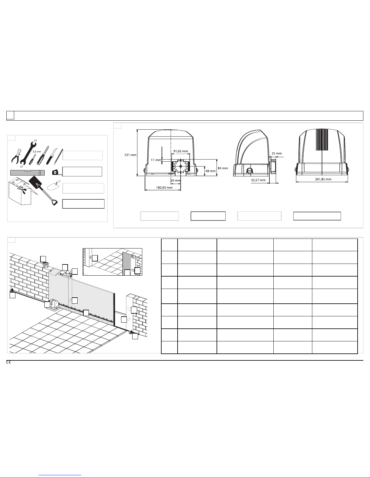
4
FF
Outillage nécessaire.
GG
Tools required.
OO
Noodzakelijk gereedschap
EE
Herramientas necesarias.
1
1
3
3
2
2
A
F Processus de montage G Assembly process O Montageproces E Proceso de montaje
4
B
C
H
D
D
F
E
E
G
G
E
E
Rep :
Vue de l’installation
terminée.
View of completed installation
Schema van de
complete instaallatie
Vista de la instalación
terminada
A Axovia 400C Axovia 400C Axovia 400C Axovia 400C
B Feu orange (option)
Orange light
(not supplied)
Oranje zwaailicht
(niet bijgeleverd)
Luz naranja
(no suministrada)
C
Antenne
(option)
Antenna
(not supplied)
Externe Antenne
(niet bijgeleverd)
Antena
(no suministrada)
D
Butée
(option)
Obligatory stops
(not supplied)
Verplichte
stootblokken
(niet bijgeleverd)
Topes obligatorios
(no suministrada)
E
Jeu de cellules
(option)
Set of electric photo cells
(not supplied)
set fotocellen
(niet bijgeleverd)
Juego de células
(no suministrada)
F Crémaillère Rack Tandheuge/tandlat Cremellera
G
Contact à clé
(option)
Key contact
(not supplied)
Sleutelcontact
(niet bijgeleverd)
Contacto mediante llave
(no suministrada)
H
Eclairage de zone
(option)
Area lighting
(not supplied)
Verlichting
(niet bijgele
v
erd)
Iluminación de zona
(no suministr
ada)
FF
Encombrement Moteur
GG
Motor dimensions
OO
Afmetingen motor
EE
Espacio requerido por el motor
 Loading...