

SOMFY Axovia-220B Installation Manual
INSTALLATION GUIDE
5101723A
www.somfy.fr
Axovia 220B
5101723A_Axovia-220B.indd 1 10/05/2011 15:37:50

5101723A_Axovia-220B.indd 2 10/05/2011 15:37:50

1
CONTENTS
GENERAL INFORMATION ___________________________________________________ 2
SAFETY _________________________________________________________________ 2
Safety instructions 2
PRODUCT DESCRIPTION ___________________________________________________ 3
Exploded diagram of the product 3
Size of motor (in mm) 4
Installation type 4
Technical specications 4
Description of operation of the indicators 5
PRE-INSTALLATION CHECKS _______________________________________________ 5
Gate 5
Pillars 5
Reinforcements 5
Area of application 5
PREPARATION AND DRILLING OF PILLARS ___________________________________ 6
MOUNTING AND FIXING OF THE MOTORS ____________________________________ 7
INSTALLING THE INTEGRATED OPENING END STOP ___________________________ 9
ELECTRICAL CONNECTIONS ______________________________________________ 10
Cable guide tting 10
Connection of the two motors 10
Aerial wiring 10
Mains cable connection 10
Locking the arms 11
QUICK COMMISSIONING __________________________________________________ 12
Storing the remote controls 12
Auto-programming the travel 12
OPERATION _____________________________________________________________ 13
ADVANCED PARAMETER SETTING _________________________________________ 13
Activating the Automatic Closure mode 13
Switching to sequential mode after activating Automatic Closure mode 13
Adding and removing remote controls 13
CONNECTING ADDITIONAL DEVICES ________________________________________ 14
Connecting the photoelectric cells 14
Photoelectric cells - 1 set 14
Photoelectric cells - 2 sets 14
Orange light 15
Key lock 15
Interphone 15
Exterior aerial 15
Backup battery 16
Area lighting 16
Digicode 16
DIAGNOSTIC AND REPAIRS ________________________________________________ 17
5101723A_Axovia-220B.indd 1 10/05/2011 15:37:50

2
This Somfy product must be installed by a professional motorisation and home automation installer, for whom this guide is intended.
This product, installed in accordance with this guide, complies with EN 12453 and EN 13241-1 standards. It is the installer's responsibility to ensure
that the automatic installation and its operation are compliant with the standards in force.
The use of any safety components not approved by Somfy remains the sole responsibility of the installer. The selected safety accessories for the
installation must comply with the current standards and regulations in force in the country in which the product is being installed.
Moreover, the installer must comply with current standards and legislation in the country in which the product is being installed, and inform his customers of the
conditions for use and maintenance for the product.
Any use outside the sphere of application specified by Somfy is forbidden. This invalidates the warranty and discharges Somfy of all liability, as does any failure
to comply with the instructions given herein.
Hereby, Somfy declares that this product is in compliance with the essential requirements and other relevant provisions of Directive 1999/5/EC. A declaration of
conformity is available on the website at www.somfy.com/ce (AXOVIA 220B), usable in UE, CH and NO.
GENERAL INFORMATION
SAFETY
Safety instructions
Important safety instructions. Follow all the instructions as incorrect installation can lead to serious injury.
This device is not designed to be used by persons (including children) whose physical, sensory or mental capacity is impaired, or persons with little experience or
knowledge, unless they are under supervision or have received instructions on using the device by a person responsible for their safety.
Check that the temperature range marked on the motors is suited to the location where the motors are to be installed.
Before installing the motor, ensure that the driven part is in good mechanical condition, that it is correctly balanced and that it opens and closes correctly.
The motor cannot be used with a driven part incorporating a small gate (unless the motor is inhibited when the small gate is opened).
Ensure that there are no danger zones (risk of crushing, cutting, trapping) between the gate and the surrounding fixed elements caused by the opening movement
of the gate.
Watch the gate while it is moving.
Place the fixed control devices and remote controls out of the reach of children.
Any switch without a locking device must be installed in direct view of the gate and away from any mobile parts. Unless it is key-operated, it must be installed at
a minimum height of 1.5 m and must not be accessible to the public.
During installation of the motorisation:
Remove any jewellery (bracelets, chains, etc.). For drilling and welding operations, wear special glasses and sufficient protection. Use the appropriate tools. Do not connect to the power source until installation is complete. -
Be careful when handling the motorisation system to prevent any risk of injury. After installation, ensure that the mechanism is correctly adjusted and that the protection system and any manual release mechanism operate correctly.
Regularly check the condition of the gate. Gates in poor condition must be repaired, reinforced or even replaced. Check that the various motorisation component's
screws and fittings are correctly tightened.
Before carrying out work on the installation, switch off the power supply.
In order to operate, the motor must be supplied with 230 V -50 Hz. The electric line should:
- solely be used for the motor,
- have a minimum cross section of 1.5 mm²,
- be equipped with protection (10 A fuse or breaker) and a differential device (30 mA),
- be equipped with an all-pole disconnection device,
- be installed in accordance with the current electrical safety standards.
It is recommended that the installation be fitted with a lightning conductor (in compliance with standard NF C 61740, maximum residual voltage 2 kV).
All 230 V lighting connected to the “zone lighting” output must be connected to earth or be of the double isolation type.
5101723A_Axovia-220B.indd 2 10/05/2011 15:37:50
3
PRODUCT DESCRIPTION
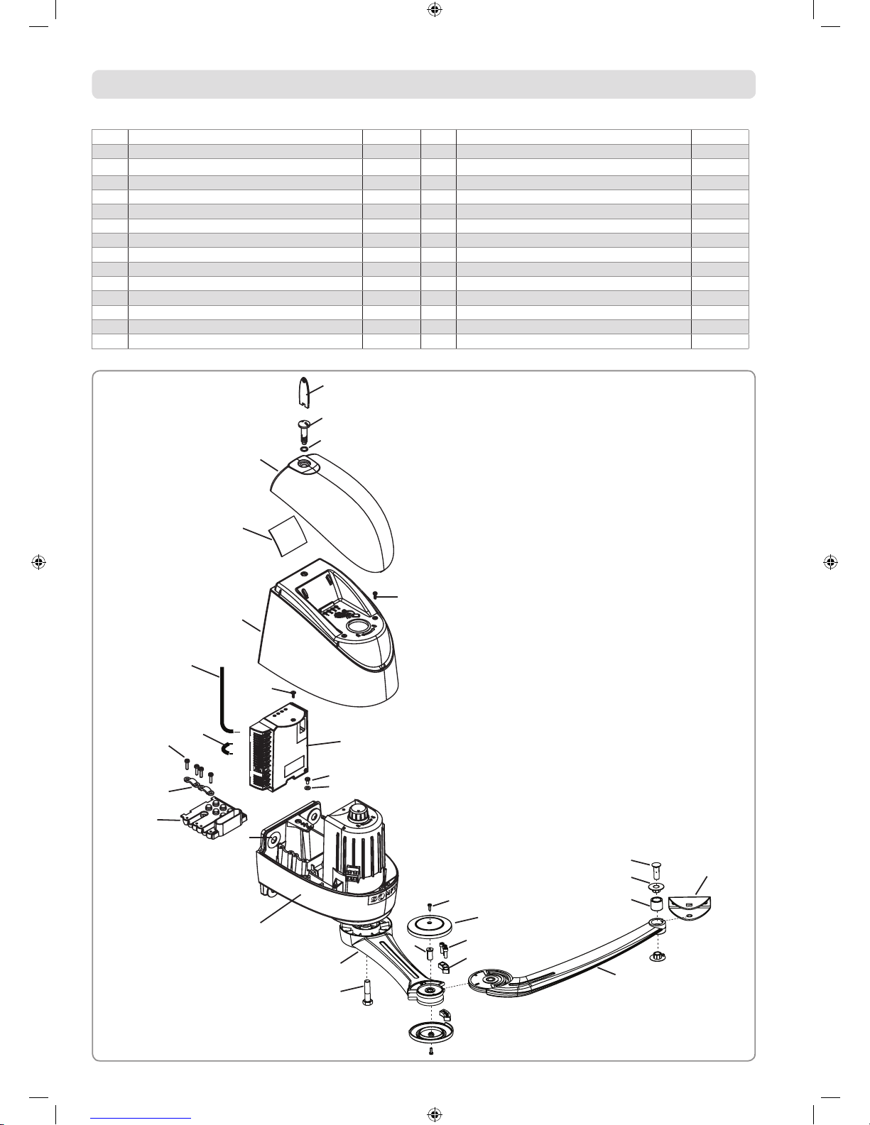
Exploded diagram of the product
1 Motor x 2 16 Cable clamp bolt x 8
2 Motor arm x 2 17 Earth bolt x 1
3 Gate leaf arm x 2 18 Earth washer x 1
4 Gate leaf bracket x 2 19 12x27 clamp washer x 8
5 Electronic unit x 1 20 Shaft bolt / motor arm HM 10x40 x 2
6 Motor cover x 2 21 End stop cover bolt x 4
7 Motor cover bolt x 4 22 End stop cover x 4
8 Information card x 1 23 End stop bolt x 6
9 Enclosure cover x 2 24 End stop (upper part + lower part) x 2
10 O-ring x 2 25 Motor arm / gate leaf arm short shaft x 2
11 Cover bolt x 2 26 Gate leaf arm / bracket long shaft x 2
12 Cover key x 2 27 Gate leaf arm ring x 4
13 Electronic unit bolt x 1 28 Gate leaf arm damper x 2
14 Grommet x 2 29 Aerial x 1
15 Cable clip x 4 30 Cell strap x 1
1
2
3
20
24
23
22
21
25
28
27
26
4
19
18
17
5
13
29
30
16
15
14
6
7
8
9
11
12
10
5101723A_Axovia-220B.indd 3 10/05/2011 15:37:51
4
Technical data
Power supply 230 V - 50/60 Hz
Standby power consumption 4.5 W
Max. power consumption 600 W
Average frequency of movements per day 20 cycles/day
Max. thrust force at 1.25 m < 15 kg EN 12453
Operating temperature -20°C to +60°C
Thermal protection Yes
Index protection rating IP 44
Integrated radio receiver Yes
Number of storable remote controls 16
Motor feed outputs 24 V DC
Power per motor 120 W
Output for orange light Flashing, 24 V, 15 W
Area lighting output 500 W max.
Accessories supply output 24 V DC / 200 mA
Backup battery input Yes
Photoelectric cell input Yes (1 or 2 sets)
Dry contact input Yes
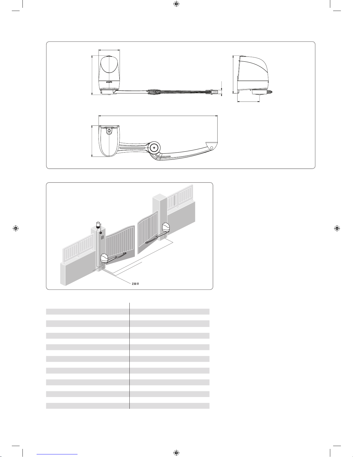
Installation type
Size of motor (in mm)
166.12
175
938.83
309.9245
30.5
297.5
5101723A_Axovia-220B.indd 4 10/05/2011 15:37:53
5
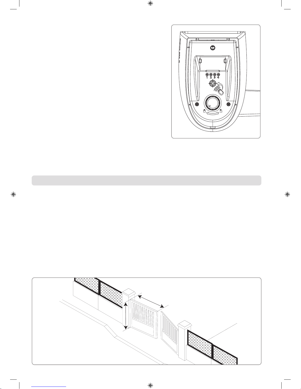
Area of application
Description of operation of the indicators
Led 1 (On/Off)
Off: Electronics off
On continuously: Electronics on
Slowly flashing: Gate heavy
Flashing quickly: Motor thermal cut-out or short circuit on motor output
Led 2 (Auto)
Off: Sequential mode
On continuously: Sequential mode + timed close
Slowly flashing: Storing closing time
Led 3 (Warning)
Off: No active input
On continuously: Cell or external command or radio transmission in process
Led 4 (Prog)
Off: Nominal operation
On continuously: Initialisation
Slowly flashing: Proximity sensor active
PRE-INSTALLATION CHECKS
Gate
The gate must be in good condition: ensure that its structure is suitable for automatic control and that it conforms to the relevant standards.
The gate must remain horizontal throughout its travel, and must open and close manually with ease. Ensure that the gate travels straight at ground level, and that
there are no sticking points that may prevent it from sliding correctly.
Pillars
The pillars are untrue so require the use of an intermediate plate.
Furthermore, when one of the motor clamp mounting holes is not resting on anything or is close to the angle of the pillar or wall, it is essential to use the
intermediate plate (ref. 2400485).
Reinforcements
If the gate has no reinforcements, prepare some metal reinforcement plates (e.g.: 15x15 cm and 4 cm thick). for mounting the brackets to the gate leaves.
L ≤ 2 m
H ≤ 2 m
P ≤ 200 Kg
5101723A_Axovia-220B.indd 5 10/05/2011 15:37:54
6
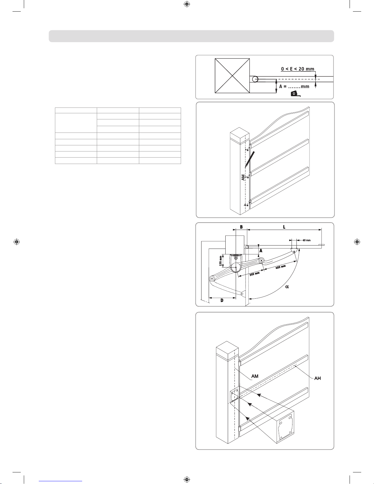
PREPARATION AND DRILLING OF PILLARS
For the indicated values, the gate leaves and their hinge pins are taken to
be on the same axis.
If the hinge pins are offset, the maximum opening angle values will be
reduced.
[1]. Measure dimension A.
[2]. Select dimension B in the table according to the required opening
angle.
A (mm) α max. (°) B (mm)
0
120 205
110 160
105 150
50 100 150
100 95 150
150 90 150
200 90 150
250 90 150
[3]. Trace axis AM on the pillar copying dimension B on the pillar.
65 mm
[6]. Trace horizontal line AH in the middle of the reinforcement, perpendicular
to the rotational axis of the gate.
If the gate has no reinforcements, place the motors approximately
1/3 of the way up the gate leaves from the bottom.
Extend this line on the pillar until it intersects with AM.
[7]. Place the template where the 2 lines intersect and drill.
[4]. Check that dimension D is greater than or equal to 435 mm.
There must be no obstacles to impede the movement of the arm in this
area.
[5]. Check that dimension L is between 800 mm and 2000 mm.
If L < 1250, the installation of a set of photoelectric cells is essential.
5101723A_Axovia-220B.indd 6 10/05/2011 15:38:19
 Loading...