

SOMFY animeo Solo Series Installation Manual
© 2007, SOMFY SAS. ALL RIGHTS RESERVED. REF. 5053517 – 01/11/07
somfy.com
UK SE DK ES FR HU IT NL NO PT RO FI CZ DE PL
Installation guide
Installationshandbok
Installationsvejledning
Guía De Instalación
Guide D’installation
Telepítési Útmutató
Guida all’installazione
Installatiehandleiding
Installasjonsveiledning
Guia De Instalação
Ghid De Instalare
Asennusopas
Instalacní prírucka
Installationsanweisung
Przewodnik Instalacji
animeo® Solo
1 zone: 1860143
2 zone: 1860144
UK SE DK ES FR HU IT NL NO PT RO FI CZ DE PL
Before installation, please read and follow these instructions.
An incorrect installation could lead to serious injury. The product
must be installed by a qualied electrician. SOMFY’s liability
for defects and damages is excluded if they were caused by
disregard of the instructions. Keep these instructions for future
reference.
Före installation, läs noggrant igenom denna manual och följ sedan instruktionerna. En felaktig installation kan medföra livsfara.
Produkten skall installeras av behörig elektriker. SOMFY’s åtaganden gäller ej om installation inte utförts enligt instruktionerna.
Spara manualen för framtida bruk.
Læs disse vejledninger omhyggeligt inden produktet installeres.
En forkert installation kan medføre alvorlige kvæstelser. Produktet må kun installeres af en autoriseret elektriker. SOMFY er ikke
ansvarlig for fejl og skader, som opstår som følge af at vejledningerne ikke følges. Gem denne vejledning til fremtidig brug.
Antes de la instalación lea y siga estas instrucciones. Una insta-
lación incorrecta puede signicar accidentes graves. El producto
debe ser instalado por un electricista profesional. La respon-
sabilidad de SOMFY por defectos y averías queda anulada si
los problemas se producen por no seguir estas instrucciones.
Guarde estas instrucciones para el uso futuro
Avant l’installation, prière de lire et d’appliquer les présentes instructions. Une installation incorrecte peut en effet provoquer des
blessures graves. Le produit doit être installé par un électricien
qualié. La responsabilité de SOMFY en cas de défauts et de
dommages est exclue si ceux-ci sont dus à la négligence des
instructions. Prière de conserver ces instructions en vue d’une
utilisation future.
A telepítés megkezdése előtt, kérjük, olvassa el, és kövesse az
alábbi utasításokat. Egy helytelen telepítés súlyos károsodáshoz vezethet. A terméket egy képzett elektrotechnikusnak kell
telepítenie. A SOMFY nem vállal felelősséget azokért a károkért
és hibákért, amelyek a telepítési utasítások gyelmen kívül
hagyása miatt jelentkeznek. Őrizze meg ezeket az utasításokat
a későbbiekre.
Leggere attentamente le presenti istruzioni prima dell’installazione. L’installazione errata può provocare gravi lesioni personali.
Il prodotto deve essere installato da un elettricista qualicato.
SOMFY declina qualsiasi responsabilità per eventuali difetti o
danni in caso di mancato rispetto delle istruzioni. Conservare le
presenti istruzioni in caso di necessità futura.
Voordat u met de installatie begint, verzoeken wij u deze instructies goed te lezen en op te volgen. Een onjuiste installatie kan
ernstig persoonlijk letsel veroorzaken. Dit product moet worden
geïnstalleerd door een erkend installateur. De aansprakelijkheid
van SOMFY voor defecten en beschadigingen vervalt als deze
instructies niet worden opgevolgd. Bewaar deze handleiding voor
toekomstig gebruik.
Les og følg disse instruksjonene før du starter installeringen. Feil
installering kan føre til alvorlig skade. Produktet må installeres av
en godkjent elektriker. SOMFY er ikke ansvarlig for skader og feil
som skyldes at instruksjonene ikke er blitt fulgt. Ta vare på denne
veiledningen for fremtidig bruk.
Antes de instalar, queira ler e seguir estas instruções. Uma
instalação errada pode causar graves danos. O produto deve ser
instalado por um electricista habilitado. A SOMFY declina qual-
quer responsabilidade por danos causados pelo não seguimento
das instruções. Mantenha estas instruções para uso como
referência no futuro.
Înainte de instalare, vă rugăm să citiţi şi să respectaţi aceste
instrucţiuni. O instalare incorectă ar putea duce la vătămări
grave. Produsul trebuie instalat de către un electrician calicat.
Răspunderea SOMFY pentru defecte şi deteriorări este exclusă
în cazul în care au fost cauzate prin nerespectarea instrucţiunilor.
Păstraţi aceste instrucţiuni pentru o consultare viitoare.
Lue ennen asennusta nämä ohjeet ja noudata niitä. Virheellinen
asennus voi johtaa vakavaan tapaturmaan. Tuotteen asennus on
jätettävä pätevälle sähköasentajalle. SOMFY ei ole vastuussa
puutteista ja vahingoista, jos ne johtuivat siitä, ettei ohjeita
noudatettu. Pidä nämä ohjeet tallessa.
Před instalací si prosím přečtěte a dodržujte následující pokyny.
Nesprávná instalace by mohla vést k vážnému zranění.
Výrobek musí být instalován kvalikovaným technikem. Právní
odpovědnost rmy SOMFY za vady a poškození se zamítá,
jestliže byly způsobeny nedodržením pokynů, uvedených v této
příručce. Příručku uschovejte pro budoucí použití.
Vor der Installation bitte die nachstehenden Anweisungen lesen
und beachten. Eine unsachgemäße Installation kann zu ernsthaften Verletzungen führen. Das Produkt ist von einer Elektrofachkraft zu installieren. Die Haftung von SOMFY in Bezug auf
Mängel und Beschädigungen entfällt, wenn die Anweisungen
nicht beachtet werden. Diese Anweisungen sind aufzubewahren.
Przed instalacją należy przeczytać poniższe instrukcje. Nieprawidłowa instalacja może doprowadzić do poważnych obrażeń.
Produkt musi zostać zainstalowany przez wykwalikowanego
elektryka. Firma SOMFY nie ponosi odpowiedzialności za uszkodzenia i szkody powstałe w wyniku nieprzestrzegania instrukcji.
Niniejsze instrukcje należy zachować w razie konieczności ich
ponownego zastosowania.

A. EXPLANATION OF USER INTERFACE
3
1. Manual command
up, stop and down
for zone 1.
2. Selector for Manual
and Automatic mode
for zone 1.
3. Cancel and
Back.
4. Navigate up,
down, left and
right on the LCD.
5. Select item.
6. Confirm setting. 7. Selector for
Manual and
Automatic mode
for zone 2.
8. Lock solar
protection up.
9. Manual
command up,
stop and down
for zone 2.
1. Mode zone 1.
Sun+Wind icon = Automatic.
Wind icon = Manual.
2. Active function zone 1.
When flashing the on or off
delay are active.
3. Position zone 1.
Flashing means moving or
locked.
4. Menu selection and information.
a. System: Enter system settings.
b. Present weather information and shortcut to ”Sensor
status”.
c. Time and shortcut to ”Set time”.
Notes:
l If the control is in ”demo” or ”test mode” the mode
toggles with ”time”.
l Black background means selected (”System” in this case).
7. Mode zone 2.
Sun+Wind icon = Automatic.
Wind icon = Manual.
6. Active function zone 2.
When flashing the on or off
delay are active.
5. Position zone 2.
Flashing means moving or
locked.
In this example you use one set of wind and sun
sensors per zone.
In this example you normally use the same set of wind
and sun sensors for both zones.
B. LCD EXPLANATION
A zone is a facade with one type of solar protection with the same dimensions.
C. WHAT IS A ZONE?
Zone 2Zone 1
Zone 1
Zone 2
Pic. 1 Pic. 2
UK
Cabling possible from back and top of the controller.
1 2 3 4 5
1
2 3
4
5
175
80
4
Wind
Precipitation
Timer Heat
Settings
Motor
Preserve heat
Get heat
Threshold
- On threshold
Advanced
Use Function
- Function used?
Threshold
- On threshold
- Off threshold
Delay
- On delay
- Off delay
Sensor allocation
- Allocation
System Sensors Time / (Demo) / (Test)
Use Function
- Function used?
Threshold
- Threshold
Delay
- On delay
- Off delay
Sensor allocation
- Allocation
Wind unit
- Unit
Threshold
- Threshold
Advanced
Use Function
- Function used?
Advanced
Use Function
- Function used?
Delay
- On delay
- Off delay
Use Function
- Function used?
Set timer
- Start time
- Stop time
Advanced
Use Function
- Function used?
Set timer
- Start time
- Stop time
Direction
- Set direction
Use Function
- Function used?
Set timer
- Start time
- Stop time
Advanced
Use Function
- Function used?
Set timer
- Start time
- Stop time
Delay
- On delay
- Off delay
Temp. threshold
- Threshold
Use Function
- Function used?
Set timer
- Start time
- Stop time
Advanced
Use Function
- Function used?
Set timer
- Start time
- Stop time
Delay
- On delay
- Off delay
Temp. threshold
- Threshold
Sun threshold
- Threshold
Sensor allocation
- Allocation
Test and Demo
- Select mode
Status
- Functions
- Sensors
Screen Options
- Contrast
- Backlight
- LCD light period (min)
Error list
- Reset error list
Alarm
- Function used?
Clock setting
- Set clock
Language
- Language chosen
Contact info
Network mode
Software version
Factory reset
Set down running time
- Time
Set tilt time
- Time
Advanced
Set down running time
- Time
Set tilt time
- Time
Set up running time
- Time
Advanced
Sun
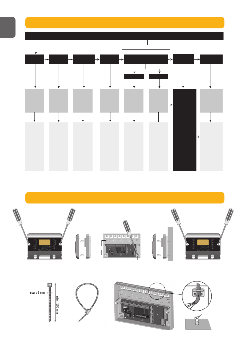
D. MENU STRUCTURE
E. MOUNTING THE CONTROLLER
UK
C
LLLNNN
Zone 1 Zone 2PEError
+ C
Ex te rna l
Com m an d
Zon e 2
1
+
1
Out
Side
2
2
+
+
C
C
C
Ext ern al
Co mm an d
Zo ne 1
RK
IB
CC
PE PE
1 1
Outside22
Zone 2 Zone 1
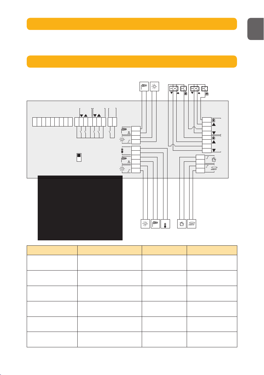
Animeo Solo to… Cable Max distance Remark
IB/Zone Switch Min: 3 x 0,6 mm2/19 AWG
Max: 3 x 2,5 mm2/ 13 AWG
1000 m/50 m
RK Min: 5 x 1,5 mm
2
/16 AWG
Max: 5 x 2,5 mm2/ 13 AWG
150 m Incl. protective earth (PE)
Mains (230 V AC) Min: 3 x 1,5 mm2/16 AWG
Max: 3 x 2,5 mm2/ 13 AWG
150 m Incl. protective earth (PE)
Motor (230 V AC) Min: 4 x 1,5 mm2/16 AWG
Max: 4 x 2,5 mm2/ 13 AWG
150 m Incl. protective earth (PE)
Sensor / Key Switch /
Error Output / Alarm
Min: 2 x 0,6 mm2/19 AWG
Max: 2 x 2,5 mm2/ 13 AWG
100 m
”L” to ”C bridge” Min: 1 x 1,5 mm
2
/16 AWG
Max: 1 x 2,5 mm2/ 13 AWG
Only use in RK mode
5
F. MOUNTING THE SENSORS
Please study the appropriate sensors installation guides.
G. GENERAL WIRING DIAGRAM
UK
 Loading...