


Pellet Insert
Instruction Manual
Models
FIRE 9KW | EARTH 9KW |
WIND 9KW
Read these instructions carefully before installing, using and servicing the unit. The
instruction manual is an integral part of the product.
Mod.814-C

1
Thank you for purchasing a SOLZAIMA appliance.
Please read this manual carefully and keep it for future reference.
* All our products fulfil the requirements of the Construction Products Directive
(Directive 89/106/EEC) and have been approved with the CE conformity mark;
* The Pellet Burning Free Standing Fires are designed according to EN 14785:2008
Standards
* SOLZAIMA disclaims any responsibility for damages to the unit if installed by nonqualified personnel;
* SOLZAIMA is not responsible for any damage to units not installed and used in
compliance to the instructions included in this manual;
* All local regulations, including but not limited to national and European standards,
must be observed when installing, operating and servicing the unit;
* Whenever you need assistance, you should contact the supplier or installer of your
equipment. You should provide the serial number of your stove that is located on the
nameplate on the back of the equipment and on the sticker s glued to the plastic cover
of this manual.
*The technical service must be performed by the unit Installer or Supplier, except on
situations where the assessment performed by the installer or service engineer
determines that SOLZAIMA should be contacted, if required.
Contacts for technical support:
www.solzaima.pt
apoio.cliente@solzaima.pt
Address: Rua dos Outarelos; nº 111;
3750-362 Belazaima do Chão
Águeda - Portugal

2
Table of Contents
1. Package Content ....................................................................................... 4
1.1. Unpacking the insert ............................................................................. 4
2. Safety Precautions .................................................................................... 6
3. Advice on action in the event of a fire in a chimney (including equipment). ...... 7
4. Technical Specifications .............................................................................. 8
5. Installing the Free Standing Pellet Fire ....................................................... 10
6. Installation of optional accessories. ........................................................... 20
7. Intallation requirements ........................................................................... 31
8. Installation for exhaust gas systems: ........................................................ 32
8.1. Installing Without a Chimney ............................................................... 33
8.2. Installation with a Chimney ................................................................. 37
9. Fuel ....................................................................................................... 38
10. Use of the pellet insert ............................................................................. 39
11. Remote Control ....................................................................................... 40
11.1. Infrared Remote Control ................................................................ 40
11.2. Control and Display Panel ............................................................... 40
11.3. Display Information Summary ........................................................ 41
11.3.1. Selecting the Manual or Automatic Mode ..................................... 41
11.3.2. Date and Time ......................................................................... 42
11.3.3. Timer ...................................................................................... 44
11.3.4. Sleep (this menu is displayed only while the unit is operating). .... 48
11.3.5. Info ........................................................................................ 48
11.3.6. Settings Menu .......................................................................... 51
12. Start-up ................................................................................................. 56
12.1. Stop ............................................................................................ 56
12.2. Turning Off the Unit ....................................................................... 56
13. Instruction for installing the frame ............................................................ 57
13.1. Choice of frame ............................................................................. 57
13.2. Installation of the frame on the equipment ....................................... 59
14. Replenishment of pellets .......................................................................... 60
15. Maintenance ........................................................................................... 63
16. Alarm / Failure / Recommendation List....................................................... 71
17. Maintenance Plan and Log ........................................................................ 73
18. Maintenance Guide Label ........................................................................ 77
19. Electrical Diagram of the Free Standing Fire Unit ......................................... 78

3
20. End of life of a pellet insert ....................................................................... 78
21. Warranty ................................................................................................ 78
21.1. Warranty general conditions ........................................................... 79
22. Annexes ................................................................................................. 86
22.1. Flow chart .................................................................................... 86
22.2. Statement of Performance .............................................................. 89

4
1. Package Content
The packaging of the equipment has the following contents:
- Pellet Insert models: Fire 9kW, Earth 9kW or Wind 9kW;
- Handle for opening the door and extracting the equipment;
- Power cable;
- Infrared remote control;
1.1. Unpacking the insert
To unpack the equipment, you must first remove the retractable bag that
surrounds the carton box. Then remove the box by lifting it up and removing
the bag wrapping the insert and the Styrofoam plates.
The insert has a fixed part and a movable part which can be separated. To
separate the two parts, first open the two safety latches under the door, use
the accessory to make it easier to open.
Figure 1 – Open safety latches

5
With the two latches open, use them as pullers to separate the movable part from
the fixed part attached to the pallet.
Notice. When you open the runner system to the limit, you notice a ledge that
locks the moving part, as the ledge passes, the slides are released and the equipment
may fall. You have to be careful that this does not occur. The movable part of the fixed
part is then separated.
The surfaces on which the parts are supported must be protected.
Figure 2 – Separate moving and fixed parts
• With the help of a star wrench PZ2 remove the two screws securing the fixed part
to the pallet, the equipment is thus completely unpacked.
Figure 3 – Separate parts

6
2. Safety Precautions
Make sure you fully read and understand the instructions contained in this manual
before using the pellet insert as a biomass heating unit.
The pellet insert is not intended for use by children or people physically and/or
mentally challenged, or that are inexperienced or unfamiliar with using the unit, except
when under supervision or after receiving proper training.
Do not touch the pellet insert when barefoot or if any part of your body are wet or
humid;
Do not tamper with the safety devices or adjustment features without the
SOLZAIMA SA manufacturer's authorization;
It is prohibited to cover or reduce the size of the ventilation openings of the
installation;
The pellet insert is an equipment that requires air to have a proper combustion, the
possible Airtightness of the place where the equipment is located or the existence of
other sources of air extraction in the house can prevent the correct functioning of the
equipment;
The existence of vents is a requirement for proper combustion;
Please keep the packing materials away from children;
During normal operation, DO NOT open the door of the unit;
Some parts may overheat during normal operation, so the direct contact with hot
parts such as the door handle and glass should be avoided;
Check for the existence of any obstructions to the fume duct before turning on the
unit after a long idle period;
The pellet insert is designed to work inside a protected environment. Safety
systems may be used to turn off the insert. If this happens, contact the after-sales
service and never in any situation disarm the safety systems;
The pellet insert is a biomass heating unit equipped with an electric fume extractor.
The occurrence of a power failure during its use may prevent the fume to be extracted,
consequently causing the room to be filled with smoke. For this reason, a natural fume
extraction system, like a chimney, is recommended;
NEVER turn off an operating Free Standing Pellet Fire unit by disconnecting the
electric plug. The fume extractor on the Free Standing Pellet Fire unit is a powered
feature, so disconnecting the power plug will prevent the extraction of combustion
fumes;

7
The unit must be disconnected from the mains power before any maintenance
procedures can be performed. Please allow the unit to cool down completely before any
maintenance operation (if operating before);
Never touch the interior of the unit without disconnecting it from the power mains.
3. Advice on action in the event of a fire in a chimney
(including equipment).
• Try to put out the fire, without risking your life.
• If you cannot put out the fire within a minute, you should call the fire department.
• Close the doors and windows or partition where the fire has flared.
• Turn off the power and close the gas before leaving your home.
• Once outside, you must wait for the firemen and be ready to give them the
following information: location of the fire, possible materials that are burning and what
they can do to prevent fire progression.

8
4. Technical Specifications
Features
Fire 9kW
Earth 9kW
Wind 9kW
Units
Weight
112
114
116
kg
Height
546
606
546
mm
Width
688
688
688
mm
Depth
573
mm
Diameter of the fume discharge pipe
80
mm
Reservoir capacity
15
kg
Maximum heating capacity
188
m³
Maximum overall thermal power
8,3
kW
Minimum thermal power
3,2
kW
Minimum fuel consumption
0,7
kg/h
Maximum fuel consumption
1,9
kg/h
Rated electrical current
106
W
Electric power at start-up (<10 min.)
350
W
Rated voltage
230
V
Nominal frequency
50
Hz
Thermal yield at rated thermal power
90,1
%
Thermal yield at reduced thermal power
96
%
Max. smoke temperature
154
ºC
Min. smoke temperature
66,3
ºC
CO emissions at rated thermal power
0,01/0,035
%
CO emissions at reduced thermal power
10,35/8,74
%
Combustion gas mass flow
6,3/2,6
g/s
Draught in the chimney
12/10
Pa
Fan Flow
48,2
dB(A)
Table 1 – Technical specifications
Tests were performed using wood pellets with a heating capacity of 4.9 kWh/kg.
The above information was obtained during product homologation tests conducted by
independent laboratories accredited for pellet unit testing.

9
General Measures
Front Back Side Top
Fire 9kW
Earth 9kW
Wind 9kW
Figure 4 – Insertable dimensions to pellets
10
5. Installing the Free Standing Pellet Fire
Before you begin the installation, perform the following actions:
The recommended measures for installing the pellet insert are as follows:
Model
Width (mm)
Height (mm)
Depth (mm)
Fire 9Kw
695
550
550
Earth 9Kw
695
610
550
Wind 9Kw
695
550
550
As can be seen in figure 4 the inserts have finishing frames to cover bigger holes,
giving greater versatility to the insert. There are two different widths, one of 44 mm
and one of 74 mm to finish the equipment’s installation (see point 13).
The surface where the base of the equipment is to be fixed must be leveled and
have the necessary strength to support the entire weight of the equipment and its
subsequent movements to load pellets.
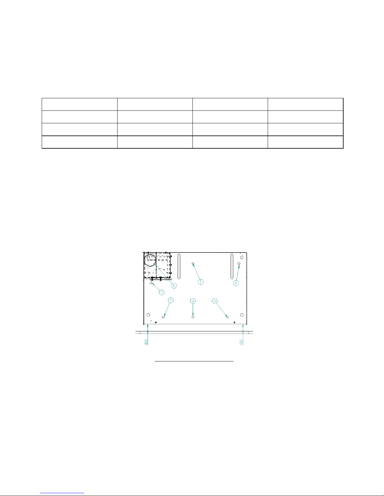
The base of the equipment has 7 holes to attach to the support.
Figure 5 – Fixing base equipment
• As can be seen in Figure 5, a distance of 62.5mm from the base to the front of the
wall must be left (it must be perfectly parallel).
• The equipment has an approximate weight of 100 kg and when it is extracted to the
pellet / maintenance position, it exerts a high force on the base, during installation it is
necessary to use anchoring material suitable for the type of base, soil and wall (In the
case of extending table), recommendations:

11
Material
Type of attachment
Image
Massive (slab, stone)
FMS M8x60 Ø10
Metallic
Massive and non-massive
(brick)
FIP M8x60 Ø10
Chemical
• It is very important that the base where the insert is installed is completely
horizontal.
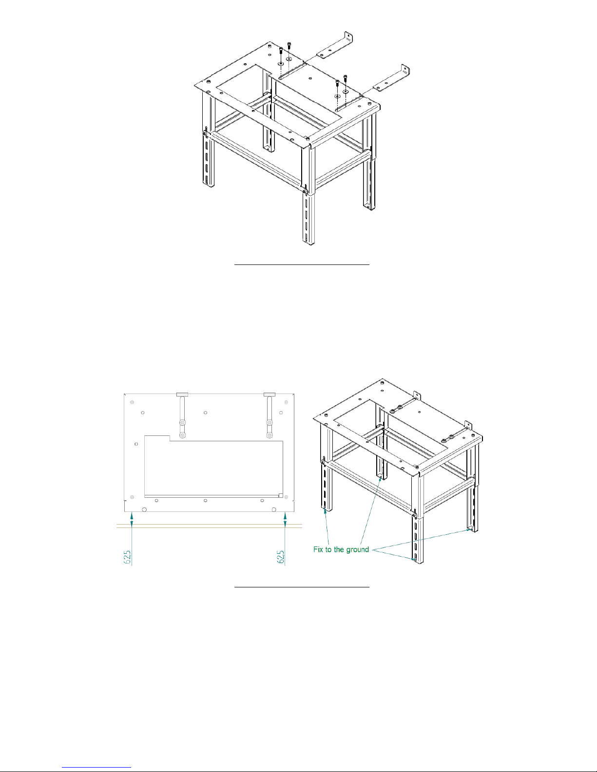
• If you do not have a base, the optional extendable table is available. This table is a
metal structure that must be fixed to the floor and to the wall. The table can be
adjustable in height between 300 mm (minimum) and 545 mm (maximum), it is very
important to ensure that the top is perfectly horizontal for the correct operation of the
equipment. Together with the extendable table, screws are deliverd to secure the base
of the insert to the table, with the same 7 screws, it is possible to attach the
equipment to an existing base. Instructions given in point 6.
Figure 6 – Optional extendable table
• Connect the 80 mm diameter pipe between the flue gas outlet and the flue outlet to
the outside of the building (eg fireplace) in accordance with the installation drawings.

12
• After securing the base of the equipment and the chimney being installed place the
moving part of the equipment as shown in figure 7.
Figure 7 – Installation
Then do a rotating motion to bring the equipment to the horizontal.
Figure 8 – Installation
Push the movable part to the wall so that it slides on the rails. Check the
correct sliding and that everything is properly attached before continuing with the
intallation. Move the equipment to the end of runner system with open safety latches
13
and once in position, close them to ensure that the equipment is properly placed in the
working position.
Figure 9 – Installation
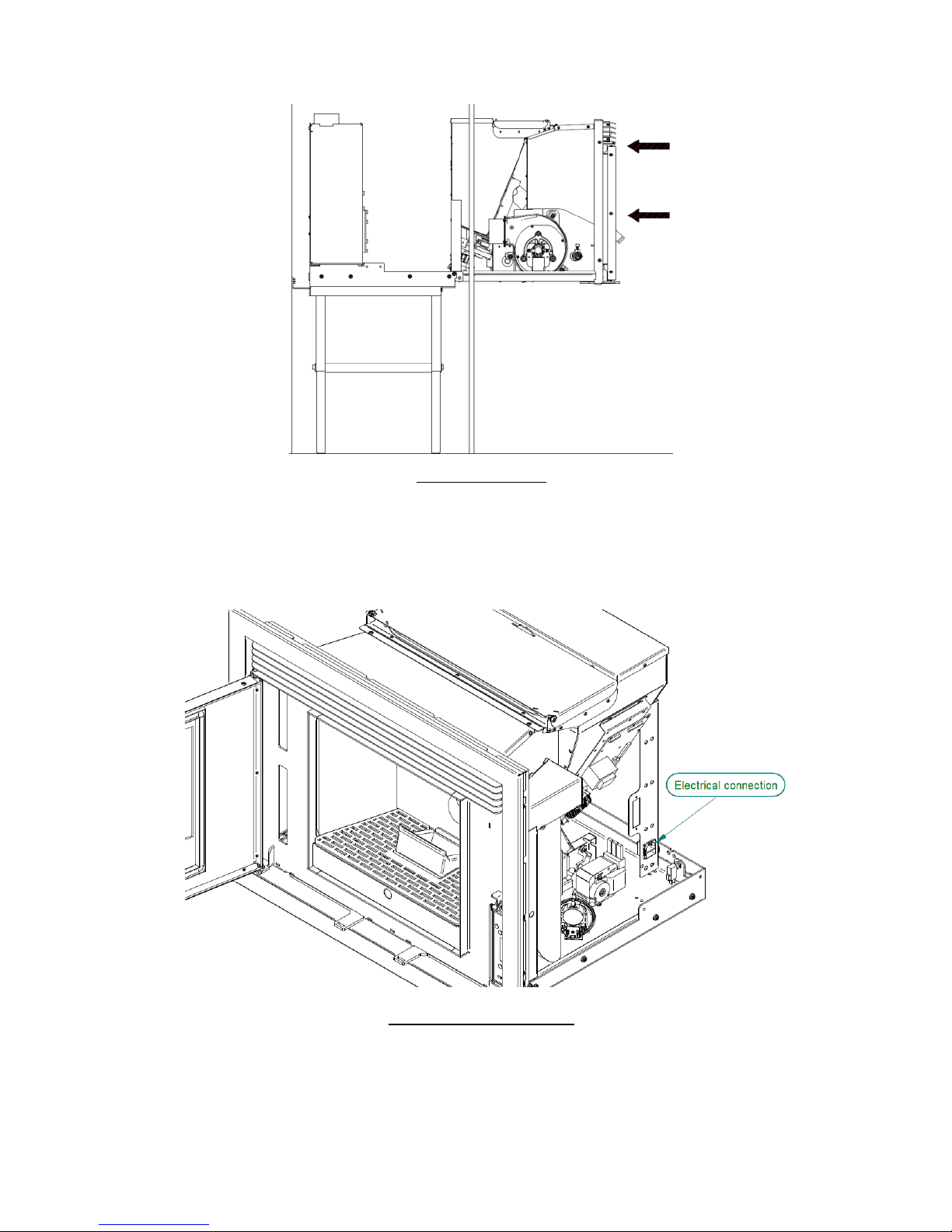
• Connect the power cord to a 230V 50Hz grounded outlet.
Figure 8 – Electrical connection
• After connecting the power cable to the silo column, it is necessary to attach the
cable to the same column and the base, making sure to leave enough cable length, so
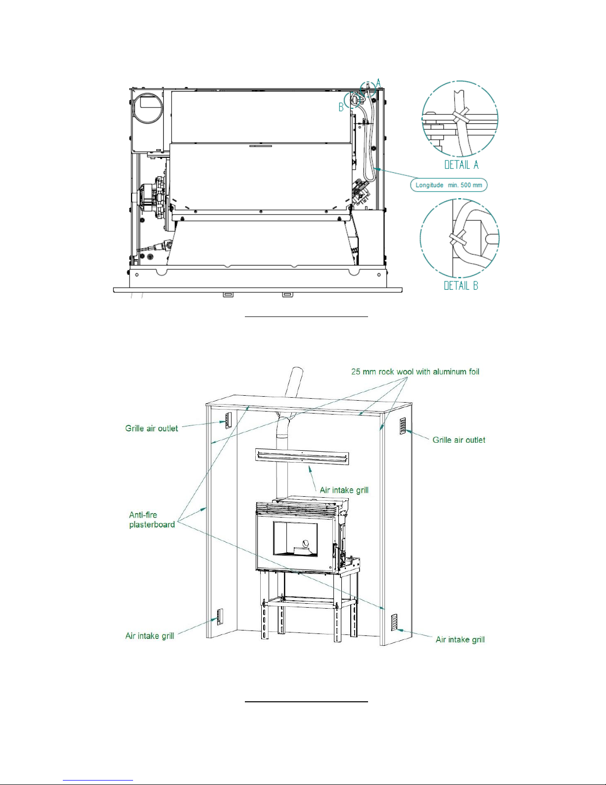
14
that the equipment can make the entire route in the rails (500 mm), without the cable
being stressed or touching the hot parts (Figure 11).
Figure 11 – Electrical connection
• Standard installation of the insert:
Figure 12 – Electrical connection

15
Instalation WIND 9kW
In case of the Wind 9kW it will be necessary to install the pellet feeding system. To
install this loading system it is necessary to open a 330x330 mm hole.
• The position of the loading system has to maintain a ratio where X is always less than
Y = X * 0.7. (See Figure 13), so that we can ensure that the slope is sufficient so that
the pellets are not trapped in the tube connecting the loading mouth with the top of
the insert structure. The loading mouth can be installed in any of the walls that form
the surroudings where the equipment is installed, either to the right or to the left, as in
the front or rear, if the layout of the house allows it. It is always necessary to respect
the minimum distances X = 390 mm, Y = 275 mm Example: X = 450 mm Y = 450x0.7
= 315 mm (minimum).
• The tube used to attach to the loading mouth and top of the insert chassis must have
an internal diameter of 200mm and must be rigid enough not to deform when the
pellets fall inside. It is recommended to apply flexible aluminum tube.
• To attach the drop tube of the pellets to the loading mouth of the top of the insert
chassis it is recommended to use metal clamps. This type of clamps provides good
clamping and sealing, and it is possible to open or close the clamp when necessary.
Figure 9 – Feeding system installation

16
• The easiest way to install the tube will be to perform the following steps:
1- Using the metal clamp, attach the pre-cut tube with the appropriate size and shape
onto its final position in the loading mouth.
Figure 10 – Installation of the loading tube and metal clamp.
2- Insert the assembly through the hole made in the wall with the above mentioned
measurement 330x330 mm, respecting the dimensions for its positioning indicated
above, it is necessary to fix the loading mouth.
3º- To be fixed to the wall, the loading system has four 6 mm holes in diameter. It is
recommended to use 8mm SX bushings for brick walls with 4.5 or 5.5 bolts and 8mm
HM bushes for plasterboard walls (Pladur) with the corresponding screws.
Figure 11 – Mouthpiece installation
4º After fastening the loading piece, place the finishing frame with the cover. Fix the
frame by tightening the 4 load screws on the wall. The cover has a pin limiting its the
opening, as can be seen in the following figure, with a cut of the base assembly,
finishing ring and loading cover.

17
Figure 12 – Equipment installation
5º- When opening the lid, the inner parts are positioned to facilitate the loading of the
pellets, for this reason it is very important that the cargo mouth is always placed in the
position shown in Figure 16.
6º- As shown in Figure 16, the WIND version has a top chassis attached to the side
columns by means of DIN912 M6 screws and DIN934 nuts. Unscrew without
completely removing the front screws (marked with the letter "A"), the cap rotates
over the rear screws, making the top cover accessible to facilitate attachment of the
flexible tube to the pellet gargle. It is necessary to join the tube leaving the loading
mouth with the cap through a metal clamp, it is necessary to make sure that the tube
has no curves where they can
Accumulate pellets. Finally, place the cover in its original position and fix the screws
again.

18
Figure 13 – Installation of the pellet insert
• The option to install a system to channel the air is only available for the version of
WIND, due to its construction, designed with superior load. To install the system you
must follow the following steps:
1º- Ensure that the fixed part of the insertable pellets is in its definitive place.
2º- The pellet loading tube installation must be carried out in the same way. Add a pipe
to channel the air (aluminum tube 100 mm in diameter) with the grid to be fixed to the
wall. It is recommended to make this union with a metal clamp. The length of the
aluminum tube should be sufficient to reach the air outlet, located on the top of the
chassis. It is necessary to repeat this step to place the second tube.
3º- To access the top of the cover (see Figure 17). It can be observed that the upper
part comes with the installation of 2 air outlets of 100 mm, with a pliers cut the micro
joints to install the tubes for the ducted hot air.
Figure 18 – Insertable pellet installation

19
4º- It is important that the bolts or rivets used to secure the air outlets be fixed from
the bottom up so that a minimum height is allowed inside the insert to not interfere
with the proper extraction of the equipment during maintenance, see Figure 18.
5º- Once the grilles are fitted, the ducted air pipes are attached to them. The use of
metal cable clamps is recommended. It is important to ensure that the air pipes are
not in contact with the exhaust pipe or pellet duct to prevent noise or vibration during
operation of the insert.
• Example of a ducted air installation:
Figure 19 – Equipment installation
• In the installation example (Figure 19), it can be verified that the pipes are placed
to channel the hot air outlet to the room where the insert is installed, but could be
installed to carry hot air to neighboring rooms. The maximum length of pipes without
installing an air extraction box is 3-4m.
• The amount of air flowing to the front of the equipment and that flowsg through the
tubes to channel the hot air can be adjusted using the accessory to open the door and
the safety latches. Put the back part of the accessory between the grate in its central
part as shown in figure 20, you can check that there is a piece that fits perfectly and is
able to rotate and move a deflector that causes the air to be directed towards the Front
or to the air pipes. For safety, there is always a minimum amount of air that has to

20
come out in front of the equipment. After adjusting the position, you must remove the
accessory to keep it cool.
Figure 20 – Equipment installation
6. Installation of optional accessories.
Installing the display outside the equipment.
It is possible to install the display outside the insert. It’s an option that allows the
installation of the display where it is most practicle, up to a maximum length of 30m
using a parallel cable with a 0.75mm2 section. In this way, the operation of the insert
can be controlled without being close to the heat source, even from another division.
This installation requires two additional components: the blind cover for the insert and
the frame to attach the display to the wall. Sufficient cable length must be left so that
the moving part of the equipment can be removed without causing strain on the cable
and does not interfere with the movement of the equipment guides. Steps for
assembly:
Once you have chosen the location where the display will be installed, you should make
a hole in the wall with the help of the plate that will support the display on the back.
Place it next on the wall, making sure it is leveled and with the help of a pencil mark
the hole as shown in the figure.

21
Figure 14 – Installing the display outside the insert
1. Place the outer support plate, making it coincide with the markings done previously
as shown in the figure with the hole, mark the 4 holes where the screws pass.
Figure 15 – Installing the display outside the device
3. With the 5 holes open, the next step is to insert the back support plate to be fixed
from the inside of the wall.
Figure 16 – Installing the display outside the device
4. On the outside, place the front support plate to match the holes previously opened,
insert the screws 4x30mm DIN7991 until it is fully threaded, leaving the two pieces
together and the wall between them.

22
Figure 17 – Installing the display outside the device
5. With all the support fixed to the wall, the display can be placed on the finishing
frame, fixing the display from the front and the box from the rear. We have to connect
the two wires of the display and must take into account that the length must be
enough to be able to remove without creating any problem or tension or interference of
the cable. Finally, the frame must be fitted with the display by attaching the bolts to
the fixing springs as shown in figure 25.
Figure 18 – Installing the display outside the device
Temperature probe installation
• The pellet inserts have a probe to measure the ambient temperature. For a correct
reading of the ambient temperature, this probe must be located on the exterior in a
place where it does not receive direct radiation or hot air from the equipment. It is
sufficient to drill a hole in the wall and fix the box screwed or glued, leaving the end of
the probe inside. Sufficient length of cable must be left so that the moving part of the
equipment can be removed without causing strain on the cable and does not interfere
with the movement of the equipment guides.

23
Figure 19 – Installation of the accessories
Installation of ventilation grille
1. The grate must be installed at the top of the wall where the equipment is installed
to allow the exit of the hot air that accumulates inside the walls, and together with
lower grates allows a natural circulation that will cool the interior walls.
Once you have chosen the place where the grill will be placed, you should drill a hole in
the wall with the help of the plate that will support the back. It should be placed on the
wall making sure that it is level, with the help of a pencil mark the hole as shown in the
figure.

24
Figure 20 – Installation of the accessories
2. The outer support plate is placed making it coincide with the markings done
previously as showed in the figure then mark the 6 holes.
Figure 21 – Installation of the accessories
3. The next step is to place the rear support plate to be fixed from the interior of the
wall
Figure 22 – Installation of the accessories

25
4. On the outside, place the front support plate to match the holes previously opened,
insert the screws 4x30mm DIN7991 until it is fully threaded, leaving the two pieces
together and the wall between them.
Figure 30 – Installation of the accessories
5. Finally you can place the grate on the wall by fitting the bolts into the fixing springs
as shown.
Figure 31 – Installation of the accessories

26
Auxiliary table installation
To perform a root installation. A height adjustable table is available to facilitate the
installation of the equipment. The table is adjustable in height and has 2 components
to regulate the depth and be able to fix it to the the back wall. It also has holes in the
lower legs to facilitate fixation to the floor.
Figure 23 – Auxiliary table installation
It is very important that the table is leveled, both in depth and width, this will facilitate
the extraction of the equipment on the guides and so increasing their life span. To level
the table it is necessary to adjust the legs in height.
The attachment to the wall and to the floor will depend on the material from which
they are made. The fastening must be very firm because the insert has a weight of
about 115 kg, for this reason, the following configurations are recommended according
to the material where the table will be fixed:
Material
Type of attachment
Image
Massive (slab, stone ...)
FMS M8x60 Ø10
Metallic
Massive and non-massive
(brick)
FIP M8x60 Ø10
Chemical
You should select the type of configuration that best suits your needs and use the
proper tools and security measures for the installation.
To assemble the table components you need a 6 mm hex key.

27
The components that make up the table are as follows:
Component drawing
Quant.
Description
19
Screw DIN912 M8x20mm
4
Washers DIN9021 M8
4
Extension for leg
4
Table leg
2
Long locking
2
Short locking
1
Table
2
Fixing brackets

28
1. Protect the surface on which you are going to work. The four legs of the table should
be attached by hand with four DIN912 M8x20mm screws as shown in figure 33.The
rest of the assembly will be easier to perform. As indicated in figure 33.
Figure 24 – Auxiliary table assembbly
2. Place one of the short locks on the inside of one of the leg extensions and insert
between the two leg extensions on one side, as can be seen in the image below. Place
one of the long interlocks on the outside and secure the assembly with a DIN912
M8X20mm bolt. Do not tighten the bolt tightly to make the rest of the assembly easier.
The leg extensions have 5 holes, you must select which to apply as well as the total
height of the table.
29
Figure 254 – Auxiliary table assembly
3. One must repeat the process for the other three legs.
Figure 265 – Auxiliary table assembly
4. Place the two set-squares through the opening on the table and put a screw and
washer in each. Do not tighten the bolts completely, just enough to allow displacement
of the brackets.
30
Figure 27 – Auxiliary table assembly
5. To place the auxiliary table in its final position, remember that the table has to be
installed 62.5 mm from the front wall, as shown in the image. Then mark the four
holes of the legs on the floor, drill the holes, you must use the necessary means of
fixing as indicated previously. At the end the table should be fixed to the floor.
Figure 28 – Auxiliary table assembly
6. You should level the table as accurately as possible with the help of a level. Tighten
all screws with a 6mm umbrako wrench. Move the squares on the back wall and mark
the holes. Remove the brackets, if necessary, remove the screws and remove the
assembly to make it easier to drill holes in the wall. Once done is put the necessary
components to fix, place the brackets in place. Check that the table is level and that it
respects the height of 62.5 millimeters. The screws that secure the table brackets must
be tightened with a 6 mm umbrako table.

31
Before finishing installation check that the table is level if necessary to correct.
Figure 38 – Auxiliary table mounting
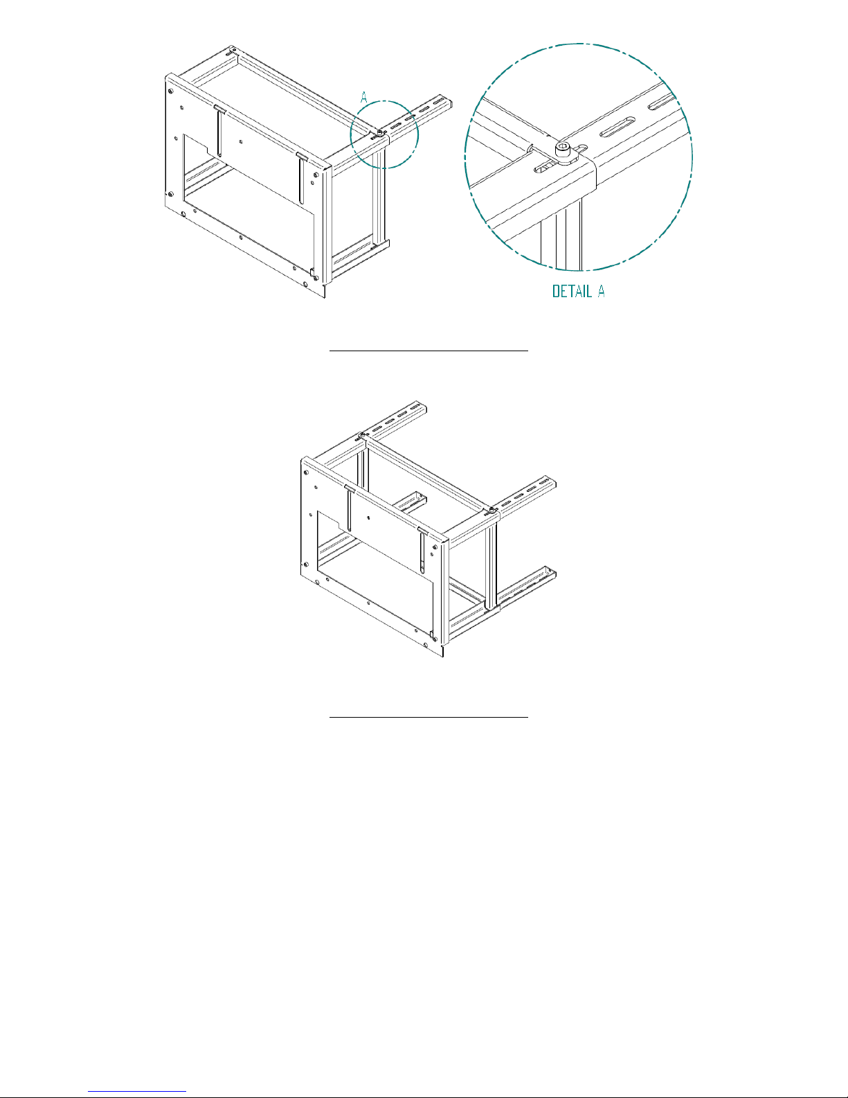
7. Intallation requirements
The minimum distances from the pellet insert to flammable surfaces as shown in figure
39.
At the top of the insert it is necessary to keep a minimum distance of 1 m from the
ceiling of the room especially if they contain flammable material in their composition.
The base that supports the insert can not be made of combustible material (eg carpet)
and adequate protection must always be provided.
a) b)
Figure 29 – Minimum distances of all surfaces: a) top view of the installation of the equipment;
b) side view of the equipment installation.

32
¡NOTICE!
Keep combustible and flammable materials at a safe distance. Never less than 5 cm
from insulated surfaces and 1 cm to non-combustible surfaces.
8. Installation for exhaust gas systems:
• The construction of the exhaust pipe must be suitable for the purpose in accordance
with local requirements and in compliance with the regulations in force.
• As shown in figure 40, the exhaust duct must be so arranged that cleaning and
maintenance are ensured by insertion of the inspection points. The insert contains a
registration cover in the smoke box for cleaning.
• Under nominal operating conditions, the drawdown of the combustion gases must
give rise to a depression of 12 Pa, measured 1 meter above the chimney neck.
• The insert can not share the chimney with other equipment.
• Tubes outside the site of use must be double insulated in stainless steel, with an
internal diameter of 80 mm.
• The exhaust pipe can generate condensation, in this case it is advisable to establish
suitable condensate collection systems.

33
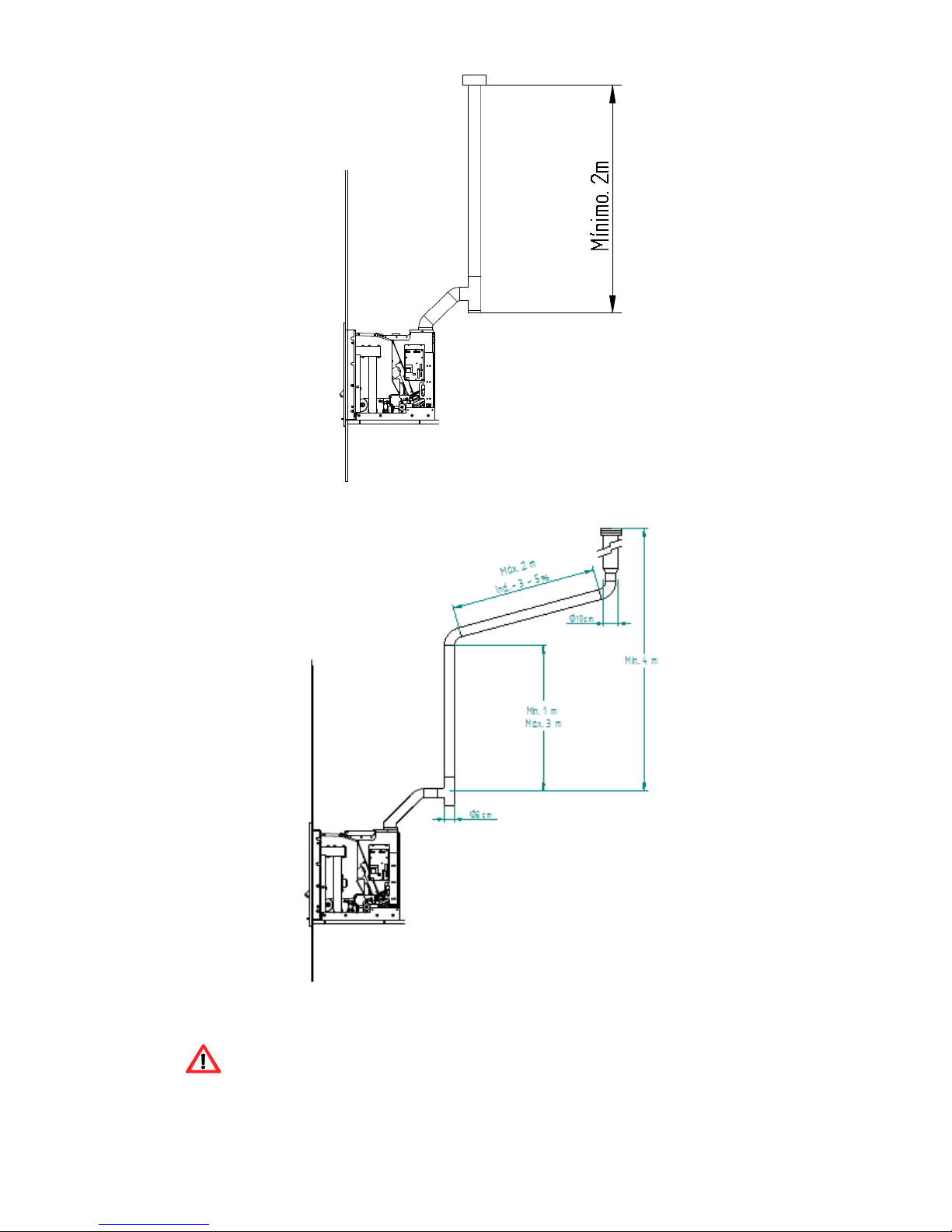
8.1. Installing Without a Chimney
The installation of the pellet insert when there is no chimney should occur, as in figure
40, bringing the exhaust pipe (with a minimum internal diameter of 80 mm) directly
out and above the roof.
Double-walled insulated stainless steel pipes should be used properly to avoid
condensation.
Provide at the base of the tubing a T for periodic inspections and annual maintenance,
as exemplified in figure 40.
Figure 30 – Side view of the installation without chimney, example of the inspection point.
In figure 41, the basic requirements for installing the insert flue are shown.
34
a)
b)
Attention. Do not use 90º curves.

35
c)
Figure 31 – Examples of installations.
Failure to comply with these requirements may prevent the correct operation of
the unit, resulting in warranty void. Be sure to follow all the instructions on the
diagrams.
Free Standing Fires operate with the combustion chamber in draught, which is
why it is absolutely necessary that they include a fume exhaust duct to adequately
extract combustion gases.
Fume duct material: The tubing must consist of 0.5mm thick rigid stainless steel,
with fitting bindings to attach the different sections and accessories.
Insulation: The fume ducts must be double-walled and insulated to make sure the
fumes do not cool down going outwards, which could cause an inadequate circulation
and condensation that may damage the unit.
Output “T-tube”: Always attach to the output of the unit a "T-tube" with a damper.
Chimney Crown: A wind shield termination must be installed to avoid fume back flow.

36
Chimney draught: The Figures below show three standard diagrams, specifying
adequate lengths and diameters. Any other type of installation must guarantee a
draught of 12 Pa (0.12 mbars) measured when hot and at the maximum power.
Ventilation: To get the optimum operation from the unit it is necessary that the
installation location has an air inlet with a minimum section of 100 cm2,
preferably near the back panel of the unit.
If the house is equipped with an air exhaust system (e.g. kitchen extractor
fan), a top ventilation section must be installed, suitable to accommodate the
different air exhaust systems existing in the household. The installation of the
unit on locations near kitchen exhaust fans or fume extractors may prevent
the unit from operating properly. It is recommended that the unit is
disconnected when these extractors are working.

37
8.2. Installation with a Chimney
As shown in figure 34, the installation of the pellet insert brings the exhaust pipe (ᴓ80
mm) directly into the chimney. If the chimney is too large, it is recommended to pipe
the gas outlet with a pipe with a minimum internal diameter of 80 mm.
Provide a "T" for the periodic inspections and the annual maintenance, as shown in
figure 42.
Figure 32 - View installation with chimney.
When atmospheric conditions are so adverse that they cause a significant disturbance
in the drawability of the insertable gases (in particular very strong winds), it is
advisable not to use the insert.
If the equipment is not used for an extended period of time, the user must ensure that
there is no blockage in the chimney tubes prior to lighting.

38
9. Fuel
The Free Standing Pellet Fire operates exclusively with pellets. No other fuel sources
are allowed to be used.
Only use pellets certified by standard EN 14961-2 grade A1 with a diameter of 6mm
and a length of 10-30mm.
The pellets may have a maximum humidity content of 8%. To guarantee a good
combustion, the pellets must maintain these characteristics so it is recommended that
they should be stored in a dry place.
The use of different pellets will reduce the efficiency of the unit and cause deficient
combustion.
Only certified pellets should be used and a sample must be tested before
buying large bulks.
The physicochemical properties of the pellets (namely, calibre, friction, density and
chemical composition) may vary within specific tolerances and across manufacturers.
Please note that this may cause changes to the feeding process and, consequently, the
need for different doses (more or less pellet quantity).
Consequently it may be necessary to adjust the pellets quantity according to its quality,
even if the pellets are certified.
The unit allows for an adjustment of ± 25% the pellet dosage at the start-up
phase and at each power level (please see section 11.3.6 of this manual).
WARNING!
This unit may NOT be used as an incinerator.

39
10. Use of the pellet insert
Recommendations
Before starting up the unit, please check the following:
- Ensure the unit is properly connected to the power mains using the 230V AC power
cable.
Figure 33 – Electrical connection plug
- Check that the pellet hopper is filled. Inside the pellet reservoir is a safety grid to
prevent users from reaching the worm screw.
The unit’s combustion chamber and panel door are made of iron plate
painted with high temperature resistant paint which releases fumes during
the initial burn due to the paint’s curing process. Avoid touching the unit
during its first burn to prevent leaving permanent marks on the paint. The
paint goes through a more plastic phase during the curing process. The curing
of the paint occurs at approximately 300ºC for 30 minutes.
Please make sure the room where the unit is installed has adequate air circulation;
otherwise, the unit will not work properly. For this reason, it is important to check if
there are any other air-consuming heating appliances present in the room (e.g. gas
units, braziers, extractors, etc.); these should not be used simultaneously with the
unit.

40
11. Remote Control
11.1. Infrared Remote Control
Figure 34 – Infrared remote control
The infrared remote control allows the user to turn the unit on and off, control the fan
airflow and increase or decrease the unit's power level.
11.2. Control and Display Panel
Figure 35 – Comand and display
.
Figure 36 – Comand keys
ON
OFF
OK
MENU
MODE
ESC
MAN
AUT
20.5ºC 16:03
OFF
a) Key to toggle between
manual and automatic mode
and exit menus (esc).
b) Key to access menus
and confirmation key (ok).
c) Key to start/stop the
unit and reset error
messages.
d) Key to scroll menus to the
left, to increase and reduce
the fan flow and increase or
reduce the set-point
temperature.
e) Key to scroll menus to the
right and increasing and to
reduce the unit's power.

41
11.3. Display Information Summary
11.3.1. Selecting the Manual or Automatic Mode
Menu indicating that the unit power is "off", the room temperature in ºC and Time.
ON
OFF + OK
MENU
MODE
ESC
-
MAN
AUT
20.5ºC 16:03
OFF
Selecting the operating mode: To select the operating mode, press the “Mode” key
to select “Manu” for manual mode or “Auto” for automatic mode.
ON
OFF + OK
MENU
MODE
ESC
-
MAN
AUT
Mode:AUTO Menu
Temp:30ºC Fan:5
Auto mode: In this mode, the unit is turned on at maximum power until reaching a
temperature 1ºC above the selected temperature (set point temperature). After
reaching the selected temperature, the unit switches to the minimum operating power.
The set-point temperature can be set between 5 and 40ºC by pressing the "-" key.
The "+" key allows the user to set the fan speed between 1-5 or to automatic
operation.
“Manu” mode”: In this mode, the unit will operate at the speed selected using the "-"
key, ranging between 1 (minimum operating power) and 5 (maximum operating
power)

42
11.3.2. Date and Time
Setting the date: press the Menu key twice until “Data” (Date) is displayed. Press “set”
to see the following menu:
Year
To set the year press “set”. The display starts to flash. Press the “+” or “-” key to
select the desired year and then “ok” to confirm. Press "esc" to return to the "Data"
(Date) menu, then press "+" to scroll to the next menu. The “Mês” (Month) menu is
displayed.
Month
To set the month press “set”. The display starts to flash. Press the “+” or “-” key to
select the desired month and then “ok” to confirm. Press the "+" key to scroll to "Dia
do mês" (Day of the month) menu.
ON
OFF + OK
MENU
MODE
ESC
-
MAN
AUT
esc 4 Set
< Mês >

43
Day of the month
To set the day of the month press “set”; the display starts to flash. Press the “+” or
“-“ key to select the desired day and then press “ok” to confirm. Press the "+" key to
scroll to the "Dia" (Day) menu.
ON
OFF + OK
MENU
MODE
ESC
-
MAN
AUT
esc 30 Set
< Dia Num. >
Day
To set the day of the week press “set”. The display starts to flash. Press the “+” or “-”
key to select the desired day and then “ok” to confirm. Press the "+" key to scroll to
the "Time" (Hour) menu.
ON
OFF + OK
MENU
MODE
ESC
-
MAN
AUT
esc 2a Set
< Dia >
Time
To set the time press “set”; the display starts to flash. Press the “+” or “-“ key to
select the desired time and then press “ok” to confirm. Press the "+" key to go to the
"Minutos" (Minutes) menu.
ON
OFF + OK
MENU
MODE
ESC
-
MAN
AUT
esc 16 Set
< Hora >

44
Minutes
To set the minutes press “set”. The display starts to flash. Press the “+” or “-” key to
select the desired minutes and then “ok” to confirm. Press the “Esc” key to exit.
11.3.3. Timer
The unit is equipped with a timer that allows the unit to be turned on or off at a
specified time.
Activation
To enable the timer press “set”. The “habilitação” (activation) menu is displayed. The
timer may only be activated after setting the configurations, as shown in the following
paragraph.
To activate the Timer mode, press “Set” - the display starts to flash. Press the “+” or
“-" key to select “On” or “Off” and then “Ok” to confirm. Press the "+" key to scroll to
the "Carga Perfil" (Profile Load) menu.

45
There are 10 weekly programmes available on the Timer (see item 17 in the annexes).
The selected programme runs from Monday to Friday and from Saturday to Sunday.
Press “set”; the display starts to flash. Press the “+” or “-“ key to select the desired
programme and then press “ok” to confirm. Press the "+" key to go to menu
"Reiniciado" (Reset).
This menu allows you to delete any programme settings. To do this, press "set". The
"Confirmar?" (Confirm?) prompt appears. Press "set" again to confirm that you want to
delete the settings or "esc" to exit.
ON
OFF + OK
MENU
MODE
ESC
-
MAN
AUT
esc Set
< Reiniciado >
The unit's programmer lets you choose from 6 different programmes for each day of
the week.
To set up programmes “P1” to “P6”, select the desired programme using the “-” and
“+” keys, and press “set” to select. The "P1 Habilitação" (P1 Activation) menu appears.
ON
OFF + OK
MENU
MODE
ESC
-
MAN
AUT
esc Set
< Prog. 1 >
Press "Set" again and when the display starts to flash, press the "+" or "-" keys to
select "On" or "Off". Press "ok" to confirm the selection. Press the "+" key to go to the
"P1 A. Inicio" (P1 A. Start) menu.

46
ON
OFF + OK
MENU
MODE
ESC
-
MAN
AUT
esc On Set
<P1 Habilita >
To set the starting time for Programme P1, press “set”. The display starts to flash.
Press the “+” or “-“ key to select the time and then press “ok” to confirm. Press the
"+" key to go to the "P1 A. Stop" menu.
ON
OFF + OK
MENU
MODE
ESC
-
MAN
AUT
esc 6:15 Set
<P1 H. Inicio >
To set the stopping time for Programme P1, press “set”. The display starts to flash.
Press the “+” or “-“ key to select the time and then press “ok” to confirm. Press the
"+" key to go to the "P1 Temp. (P1 Air Temp.) menu.
ON
OFF + OK
MENU
MODE
ESC
-
MAN
AUT
esc 20:15 Set
<P1 H. Stop >
To set the set point temperature for Programme P1, press “Set”. The display starts
to flash. Press the “+” or “-" key to select the desired temperature, followed by “Ok” to
confirm. Press the "+" key to go to the "P1 Temp. Água” (P1 Water Temp.) menu.
ON
OFF + OK
MENU
MODE
ESC
-
MAN
AUT
esc 18ºC Set
<P1 Temp. Ar >

47
To set the operating power level (1 to 5) of Programme P1, press “Set”. The display
starts to flash. Press the “+” or “-" key to select the desired power level (1 to 5), and
then “Ok” to confirm. Press the "+" key to go to the "P1 Dia" (P1 Day) menu.
To select the days of the week that you want P1 Programme to run, press "set" and
then select the day of the week using the “-” and “+” keys. Press “set”. The display
starts to flash. Select "On" or "Off" using the "-" and "+" keys. Press "ok" to confirm
the selection. Press the "esc" key to go to the "P1 Dia" (P1 Day) menu. Press "esc"
twice and then "+" to access the "Configurações" (Configuration) menu.
Repeat the above steps for programmes P2 to P6.
Note:
- Once the programmes are set, remember to enable them on the
"Habilitações" (Activation) menu.
- There can only be one enabled profile in the Timer, either weekly or daily
(they do not operate simultaneously).

48
11.3.4. Sleep (this menu is displayed only while the unit
is operating).
The "Sleep" menu allows you to setup the time you want the unit to turn off.
ON
OFF + OK
MENU
MODE
ESC
-
MAN
AUT
esc OFF Set
SLEEP
Press "set". The display starts to flash. Select the desired time using the "-" and "+"
keys. After choosing the time, press "ok" to confirm. Press "esc" to return to the menu
and "+" to go to the configuration menu.
ON
OFF + OK
MENU
MODE
ESC
-
MAN
AUT
esc 22:00 Set
SLEEP
11.3.5. Info
This menu contains information on the Free Standing Fire unit. Press "set"; the "Código
de Ficha" (File Code) menu appears.
Software code / Motherboard firmware. Press the "+" key to scroll to the “Código de
Segurança” (Security Code) menu.

49
Software code / Security firmware. Press the "+" key to scroll to the “Código Display”
(Display Code) menu.
ON
OFF + OK
MENU
MODE
ESC
-
MAN
AUT
esc 520420
< ódigo Seguranç >
Software code / Display firmware. Press the "+" key to scroll to the “Código de
Parâmetros” (Parameter Code) menu.
ON
OFF + OK
MENU
MODE
ESC
-
MAN
AUT
esc 500308
< Código Display >
Parameter code. Press the "+" key to scroll to the “Horas de Trabalho” (Operation
hours) menu.
This menu shows the unit's current operating hours.
ON
OFF + OK
MENU
MODE
ESC
-
MAN
AUT
esc 144
< de Funcioname >

50
This menu shows the number of operating hours the unit has registered since its last
servicing.
ON
OFF + OK
MENU
MODE
ESC
-
MAN
AUT
esc 144
< oras de Serviç >
The number of hours at which the next servicing should take place.
This menu shows the phase/status of the free standing fire.
Fume extractor operating speed (rotation per minute).
ON
OFF
+
OK
MENU
MODE
ESC
-
MAN
AUT
esc 49 rpm
< Expulsor Fumos >
Theoretical pellet consumption.

51
Fume temperature.
ON
OFF
+
OK
MENU
MODE
ESC
-
MAN
AUT
esc 18ºC
< emperatura Fum >
Worm drive rotation "On" time.
11.3.6. Settings Menu
To modify the unit's settings, press "Set". The "Língua" ("Language") menu should
then appear, allowing the user to choose a set language.
ON
OFF + OK
MENU
MODE
ESC
-
MAN
AUT
esc Set
< Configurações >
Language
To select the language, press “set”. Using the “+” or “-” keys, select the language (Pt
– Portuguese; Nl – Dutch; Gr – Greek; Tr – Turkish; It – Italian; En – English; Fr –
French; Es – Spanish; De – German). Press "ok" to confirm. Press the "+" key scroll
go to the "Eco" menu.

52
Eco mode
When the “ECO” mode is enabled at the same time as the Thermostat feature, the unit
will operate at maximum power until the thermostat opens contact (NO). The unit then
will operate at minimum power for a preset period of time (Shutdown delay time:
factory setting: 20 minutes). Once the preset time is elapsed, the unit shuts down. At
the start of the Shutdown phase, another timer for a different preset period of time is
triggered (Start-up delay time: factory setting: 20 minutes), that will make the unit
enter the activation phase, when the thermostat closes contact (NC)
Start-up delay time (Delay time On): The delay time that elapses between the
moment the thermostat closes (NC) until the unit is activated.
Shutdown delay time (Delay time Off): The delay time that elapses between the
moment the thermostat opens (OC) until the unit starts to shutdown.
Note: When using the feature for the first time, you must press the On/Off button in
the display. To enable the eco mode, press “set”. The display starts to flash. To activate
the eco mode, press "set". The display starts to flash. Select "On" or "Off" using the "-"
and "+" keys. Press "set" to confirm the selection. Press "esc" to return to the previous
menu and then press "+" to go to the "Iluminação" (Lighting) menu
ON
OFF + OK
MENU
MODE
ESC
-
MAN
AUT
esc Off Set
< Eco >
Lighting
To select lit screen, press “set”. The display starts to flash. Press the "+" or "-" key to
select the time for the screen to light up, or select "On" to keep the light permanently
on. Press “ok” to confirm. Press the "+" key to go to the "Controlo remoto" (Remote
control) menu.

53
ON
OFF + OK
MENU
MODE
ESC
-
MAN
AUT
esc On Set
< Iluminação >
Remote control
This feature enables and disables the remote control, when the user wants to operate
the unit's thermostat remotely. Press "Set" and use the "+" and "-" keys to select the
"On" or "Off" mode. Press "Ok" to confirm. Press the “+” key to go to the “Unidade de
temperatura” (Temperature units) menu.
ON
OFF + OK
MENU
MODE
ESC
-
MAN
AUT
esc On Set
<Controle Remoto>
Note: Some TV remote controls share the same frequency as the unit’s remote control,
possibly influencing the unit's operation. If this is the case, it is recommended to
disable the remote control feature.
Temperature unit (ºC/ºF)
To select ºC / ºF, press “set”. The display starts to flash. Press the “+” or “-” key to
select “ºC”, “ºF” or “Auto”, and then “ok” to confirm. Press the "+" key to go to the
"Combustion recipe" menu.
ON
OFF + OK
MENU
MODE
ESC
-
MAN
AUT
esc Auto Set
< ºC / ºF >

54
Combustion recipe
Press "set" to display the "Combustão receita" (Combustion recipe) menu.
- Pellet
This feature allows the user to increase or decrease by 25% the pellet quantity
during the start-up and power process. Press "set". The display starts to flash.
Press "+" or "-" to increase or decrease (between -10 to +10), as required. Each unit
must be multiplied by 2.5 to obtain the correct percentage. Press “ok” to confirm. Press
the "+" key to go to the "Ar" (Air) menu.
- Air
This feature allows the user to increase or decrease by 25% the rotation speed of
the fume extractor during the start-up and power process. Press “set”. The
display starts to flash. Press the "+" or "-" key to increase or decrease (from -10 to
+10), as required. Each unit must be multiplied by 2.5 to obtain the correct
percentage. Press “ok” to confirm. Press "esc" to return to the "Receita de pellets"
(Pellet recipe) menu and then press "+" to go to the "Carga pellet" (Pellet loading)
menu.

55
Pellet loading
This feature allows you to enable the worm drive to fill the channel when it is empty
to keep the unit running. Press "set"; the "ok" option appears. Press "ok" to activate
the drive; the message "habilitada" (enabled) is displayed. Press "esc" to stop. Press
the "+" key to go to the "Limpeza" (Cleaning) menu.
Cleaning
This feature allows you to clean the burning basket manually. Press "set"; the "ok"
option appears. Press "ok" to start the cleaning procedure; the "Habilitada" (Enabled)
message is displayed. To stop, press "ok". Press the "+" key to go to the "Técnico"
(Technical) menu.
The technical menu is not available to the end user.

56
12. Start-up
After loading the pellets into the deposit (see chapter 13), press and hold the ON/OFF
button for 3s, to start the Free Standing Fire. During the lighting phase, the display will
show the message “Ativação” (Activation) until this phase is completed.
The pellets are fed through the supply channel to the burning basket (combustion
chamber), where they will be ignited using a heat resistor. This process may take 5 to
10 minutes, depending on whether the worm screw used to push through the pellets
has been previously filled with fuel or is empty. Once the ignition phase is completed,
the message "On" appears on the display. The heating power can be adjusted at any
time by pressing the power selection button for approximately 1 second. You can select
from the five pre-set power levels that are available. The selected power is indicated on
the display. The initial power status at each start-up will correspond to the power level
set before the last stop.
Important notice: Before starting up the unit, please check to determine
if the deflector plate is in place.
12.1. Stop
The stop sequence of the unit is started by pressing the ON/OFF button for 3 sec.
The display will show “Desativação” (Disabling) until full completion of this phase.
The extractor will operate until the fume temperature of 64ºC is reached, to guarantee
that all the material has been burnt.
12.2. Turning Off the Unit
The unit should only be disconnected after its full stop. Make sure the “Off” shows on
the display before disconnecting the unit. If necessary, disconnect the power cable
from the mains.

57
13. Instruction for installing the frame
13.1. Choice of frame
Before installing the frame, it must be immediately verified that the packaging is
complete and in perfect condition, any damage or lack of components must be
reported before installation.
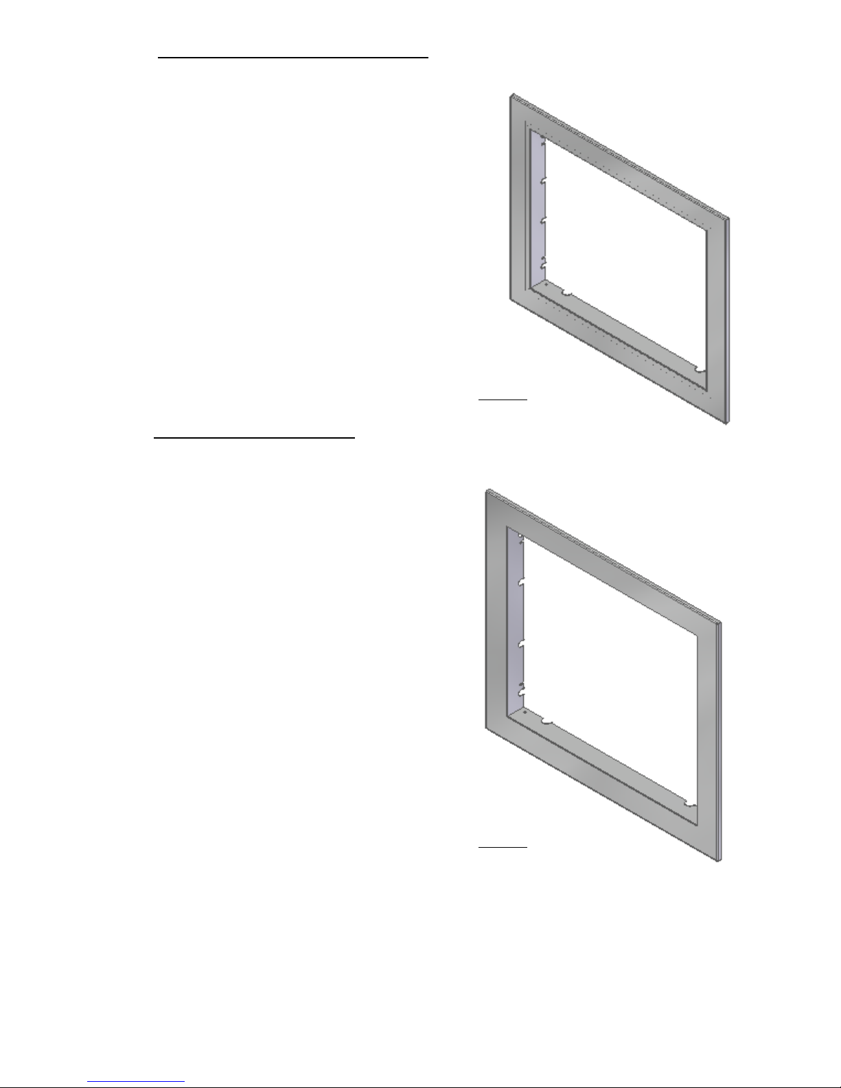
On this equipment it is possible to install different finishing frames.
To install the frame you must first check that the frame is compatible with the insert:
Thin Frame (Fire and Wind 9Kw)
Interior measurements:
685x536mm
Hoop width 44mm
Ref. MO1160N017
Figure 37
Thin Frame (Earth 9Kw)
Interior measurements:
685x596mm
Hoop width 44mm
Ref. MO1160N015
Figure 38
58
Wide frame (Fire and Wind 9Kw)
Interior measurements:
685x536mm
Hoop width 74mm
Ref. MO1160N018
Figure 39
Wide frame (Earth 9kW)
Interior measurements:
685x596mm
Hoop width 74mm
Ref. MO1160N016
Figure 40

59
13.2. Installation of the frame on the equipment
With the fixed insert and the tripartite frame prepared, the next step is to assemble the
two. Open the safety catch of the insert, remove the insert to work comfortably. On
each side of the insert we have two screws (Din 967 M4x8mm), it is necessary to
slightly loosen these screws. (See Figure 50).
Figure 41 - Locating the screws to attach the frame to the insert
Insert the frame, aligning the insertable bolts with the frame flaps, insert the frame,
line up in front of the insert and tighten the screws again to secure the rim (See Figure
51). Place the insert in its operating position and close the two safety latches, if the
wall is sensitive to marks it is recommended to leave 1 or 2 mm distance between the
rim and the wall.

60
Figure 42 – Installing the frame
VERY IMPORTANT: You should always read the instruction manual of the
equipment before proceeding with its installation.
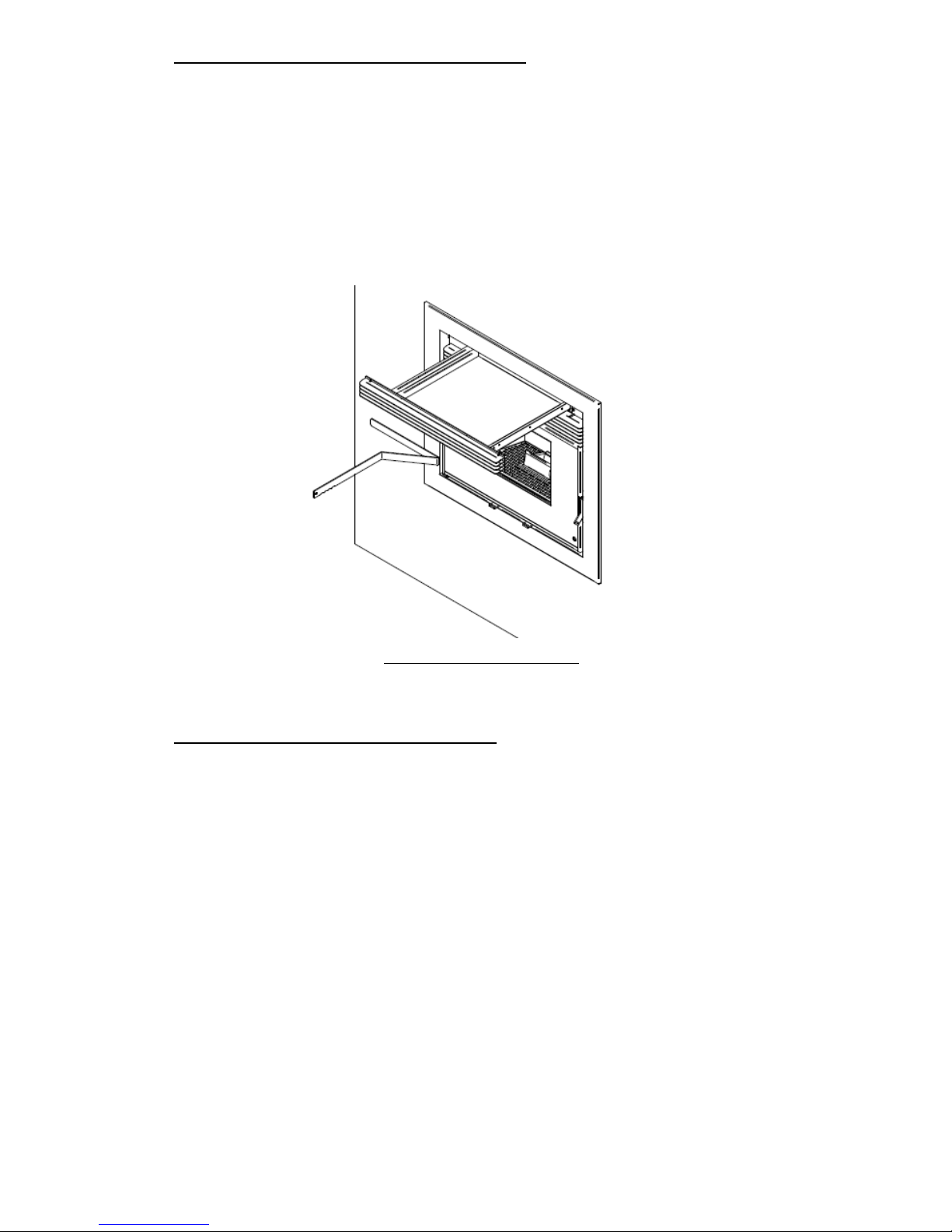
14. Replenishment of pellets
Depending on the type of insert, refueling will be done in one of the following ways:
Insertable with replenishment by extraction of the body.
If the refueling is by extraction the first thing we should know is we can never refuel
with the equipment in operation.
It must always be replenished when the insert is completely disconnected, because
when extracting the insert from the operating position the smoke extractor is
disconnected from the smoke box and this can cause smoke to flow out to the room
where it's installed.
To refill disconnect the equipment, open the located safety latches under the door.
Using these latches, remove the equipment completely (figure 53).

61
Figure 43 – Extraction of the insert to refuel
At the top of the equipment we can see the lid of the pellet tank. We open completely
by rotating until it touches the front (figure 54).
After refueling, close the cover and put the insert into its working position, finally close
the safety latches.
Figure 44 – Pellet Reservoir Lid Opening
62
Insertable with refill per load drawer.
This charging system can be used with the equipment in operation, but always with
care as you will be close to sources of heat.
To refill the tank open the cargo drawer by pulling the upper grate completely. Pour the
pellets into the drawer and with the aid of the accessory the pellets should be pushed
to the back of the drawer. The pellets will fall into the tank. When the pellets stop
falling and begin to accumulate in the drawer stop loading.
Figure 45 – Drawer for refuelling
Insertable with top-load refueling.
This top loading system can be used with the equipment in operation because it does
not interfere with the normal operation of the insert and depending on where the
loading mouth is placed it will not be near the heat source, you can observe the
installation of this system in the Point 4. The installation of the equipment is restricted
to the height and distance to install the respective loading mouth. The mouth can be
installed on the right, left, forward or, if possible, evenly distributed through the back
of the equipment. To load the pellets simply open the loading door, the door has stops
that will open the door in a certain position to facilitate loading, causing a ramp effect
for the pellets to enter the tube into the tank. When checking that the pellets are about
to reach the loading mouth, do not put more and you should close the door.

63
Figure 46 – Loading head for refueling
15. Maintenance
Maintenance is a work of overhaul and mainly cleaning. The periods marked in this
manual are indicative and the dirt on the equipment varies greatly according to usage
and fuel.
Note: Before performing any cleaning, it is imperative that the insert is off and
sufficiently cold in order to avoid accidents.
Daily Maintenance
The insertable pellet requires strict maintenance. The main care is the regular cleaning
of the ashes in the pellet burning chamber. This can be done in a practical way through
the aid of a simple vacuum cleaner. The cleaning operation must be performed after
each firing of approximately 30 kg of pellets.
To perform this maintenance, you must open the door with the aid of the accessory.
Clean the drawer and the grate. Then remove the burner and empty the ashes.

64
Figure 47 – Opening of the door
Weekly Maintenance
Open the door, clean the debris that may be on the grate before removing it, remove
the grate, drawer and burner (Figure 58) and vacuum the ashes. Make sure all burner
holes are clear, clean the inside of the insert. Finally, put the components in reverse
order.
Figure 48 – Weekly cleaning

65
Additional Cleaning
Every 600-800 kg of pellets, an additional cleaning should be carried out.
Open the door, clean the debris that may be on the grate before removing it, remove
the grate, drawer and burner, once removed, remove the baffle plate, which is on top
of the combustion chamber (figure 59).
Figure 49 – Removal of the baffle plate
Remove the vermiculite plates lining the inside of the combustion chamber, first
remove the sides and then the back. This shows the parts separating the combustion
chamber from the smoke passage (Figure 60).
Figure 50 – Combustion chamber separators
Using a nº5 hex wrench, remove the two DIN912 M6x12 screws securing the lower
spacers (Figure 61). Once removed, the top separators are easily removed, the smoke

66
passage in the rear of the combustion chamber should be cleaned using a vacuum
cleaner and a vacuum cleaner to clean the combustion chamber, the top-floor heat
exchanger, The ash basket area and the lower part of the combustion chamber.
Figure 51 – Fume passage cleaning and cast iron heat exchanger
Cleaning the Glass
Allow the unit to cool down completely before cleaning the glass. For cleaning, use a
specific product following the instructions of the label. Avoid contact between the
product and rope gasket and painted metal parts of the unit, as this may cause
oxidation. The rope gasket is fixed with glue so any contact with water or any other
liquids must be avoided.
Figure 52 – Incorrect cleaning of the glass

67
Figure 53 – Cleaning the glass: Applying liquid to the cloth
Figure 54 – Cleaning the glass: Cleaning the glass with the cloth
Annual cleaning
For the next cleaning task, it is necessary to remove the insert. With the door closed,
open the two safety latches located under the door using the accessory (figure 65).
On the left side of the equipment you can access the smoke extractor, as shown in
figure 65.

68
Figure 55 – Smoke extractor view
The smoke extractor is located on the left side of the equipment, it’s mainly composed
of two parts, the body and the motor. To clean the extractor it is necessary to remove
the cap with the motor, remove the screws as shown in Figure 66 with a Phillips
screwdriver (PH2). You can use a brush and a vacuum cleaner to remove any dirt from
the extractor walls and propellers.
Figure 56 – Smoke extractor view

69
The second part of the cleaning requires the complete removal of the moving part of
the equipment. The first thing to do is to disconnect the power cord and the
connections if there is external probe or chrono-thermostat.
We remove the equipment from its fixed base. At the rear of the fixed base, to the left
we have the smoke box that is connected to the chimney. On the front there is a red
silicone gasket that is responsible for making the connection between the extractor and
the smoke box, it must be checked that this gasket is in good condition. The joint can
not have cracks or cuts and must be flexible, if it is not in good condition it is
necessary to replace. The smoke box on the right side has a fixed cover with screws 6
DIN912 M6x12 (see figure 67), it is necessary to remove this cover to gain access to
the inside of the box and clean (see figures 68).
Figure 57 – Smoke box cover
Inside the box there are two smoke deflectors, positioned as shown in figure 68, to
carry out a proper cleaning it is necessary to remove them.

70
Figure 58 – Smoke box cover
To remove the baffles, you first have to remove 2 M6x20 DIN 912 screws as shown in
figure 69. Clean the inside of the smoke box and replace the
baffles.
Figure 59 – Smoke box deflectors
Finally, replace all the parts in reverse order of their disassembly, finally close the
safety locks under the door.
NOTICE! The frequency of maintenance tasks depends on the quality of
the pellets.

71
16. Alarm / Failure / Recommendation List
Table 2 - List of alarms
Important notice: when triggered, all the alarms above cause the machine to
shutdown. The alarm must be reset and the unit restarted. To reset the unit, press the
“On/Off” button for 10 seconds until the alarm sounds.
Alarm
Code Troubleshooting
Ignition failure
A01
Maximum time 2400 s
- the worm drive channel is empty - restart the unit
- resistance burnt – replace resistance
- burning basket incorrectly installed
- Locked worm - unlock
- Smoke temperature ñ exceeded the value
defined in the captivation
No flame or insufficient
quantity of pellets
A02
Temperature under :
- 40 °C (Air Version)
- 43 °C (Douro 24 kW);
- 50 ºC (Douro 17 kW)
- Pellet reservoir is empty
Pellet drum temperature
is too high
A03
110 °C
- the fan is not working – call for assistance
- faulty thermostat - call for assistance
- faulty ventilation of the unit
Fume temperature is too
high
A04
Over 230 °C (Air
version);
Over 260 °C (Water
version)
- the fan is not working or is working at a low
speed - increase level to the maximum (if the
problem persists, call for assistance)
- Insufficient extraction
- Excess pellets - Faulty smoke sensor
Pressure regulator alarm
A05
Door open, draught too
low or extractor fault for
60 sec
- close the door and clear the error message on
the faulty pressure switch
- obstruction of the exhaust pipe or faulty extractor
Air mass sensor
A06
40 lpm Delta for 3600 s
- Piping with insufficient draft or obstructed tubing
The door is open
A07
Door open for 60
seconds
- close the door - clear the error message
- Faulty air mass sensor
Fume extractor failure
A08
Connection failure
- check connection
- Check that the fan is not blocked
Fume probe failure
A09
Connection failure
- check connection
Pellet resistor failure
A10
Connection failure
- check connection
- Faulty resistance
Worm drive failure
A11
Connection failure
- check connection
- Failed worm motor
Pellet level sensor alarm
A15
- check connection
Water pressure out of
operating range *
A16
- check connection
- Check pressure in the hydraulic circuit
- Adjust pressure (1 bar) in the hydraulic circuit
(working range 0.5 to 2.8 bar)
Excess water
temperature *
A18
- check connection
- Check that the pump is working
- Bleed hydraulic circuit
- Check that the heat sinks are open

72
- Failures
Failures
“Service” (Maintenance)
Air sensor failure
The door is open
Air temperature probe failure
Table 3 - List of failures
Important notice: A “service” warning on the display (maintenance due) indicates
that the unit has exceeded 2100 operating hours. In this case, the client must perform
the unit's maintenance procedure (following the instruction on the Technical Manual).
Once this procedure is completed the hour meter may be reset, to clear the waning
message. This message does not impact the normal operation of the unit. It is simply a
warning.
Important notice: The errors can be reset only when the error information is
flashing on the display. To reset the error, press the ”Mode” button once while
displaying the error.
WARNING!
In case of an emergency, turn off the unit by following the normal shutdown procedure.
WARNING!
THE UNIT BECOMES HOT DURING OPERATION SO CARE MUST BE TAKEN
ESPECIALLY WHEN HANDLING THE DOOR GLASS AND DOOR HANDLE.
73
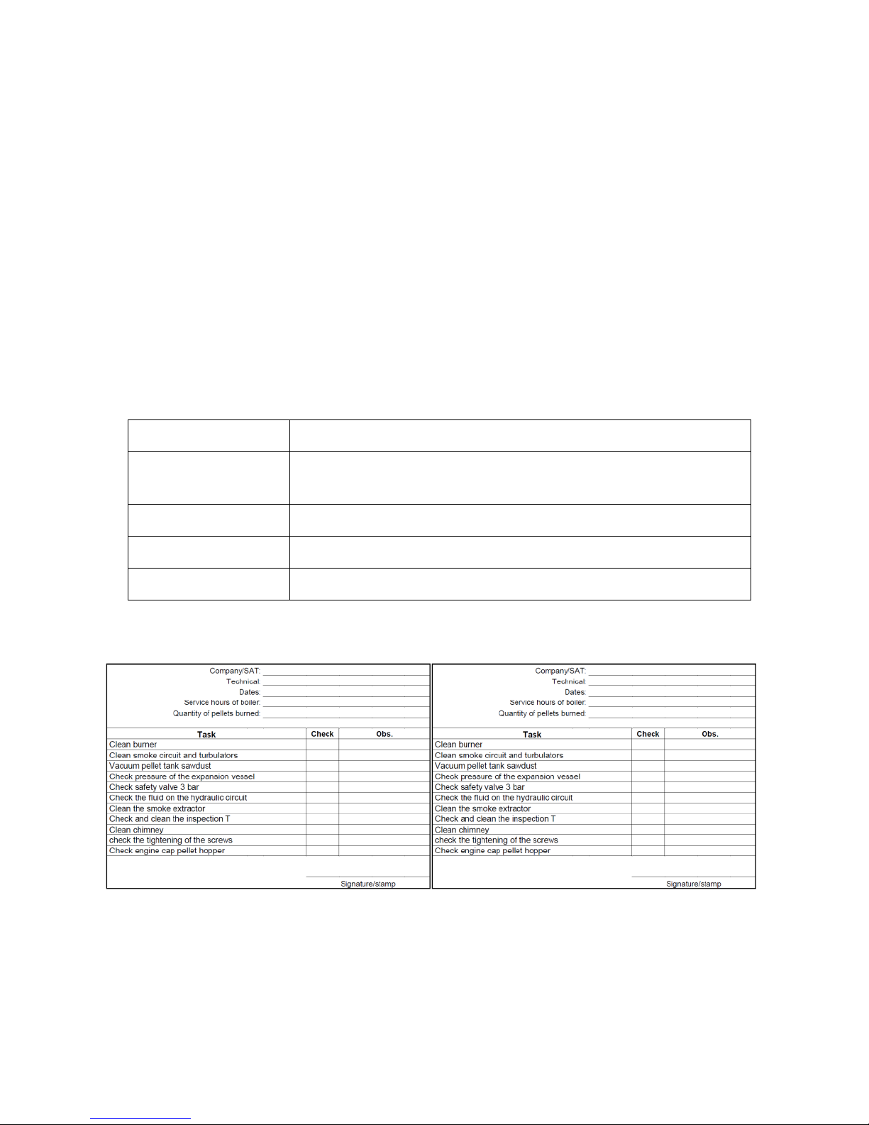
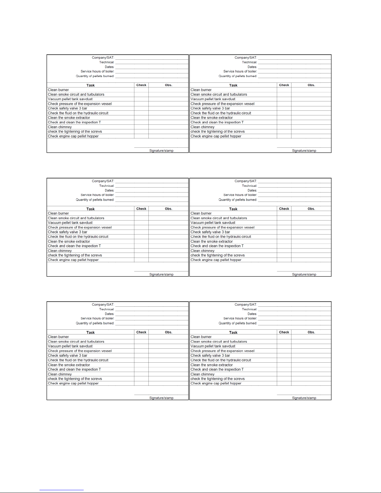
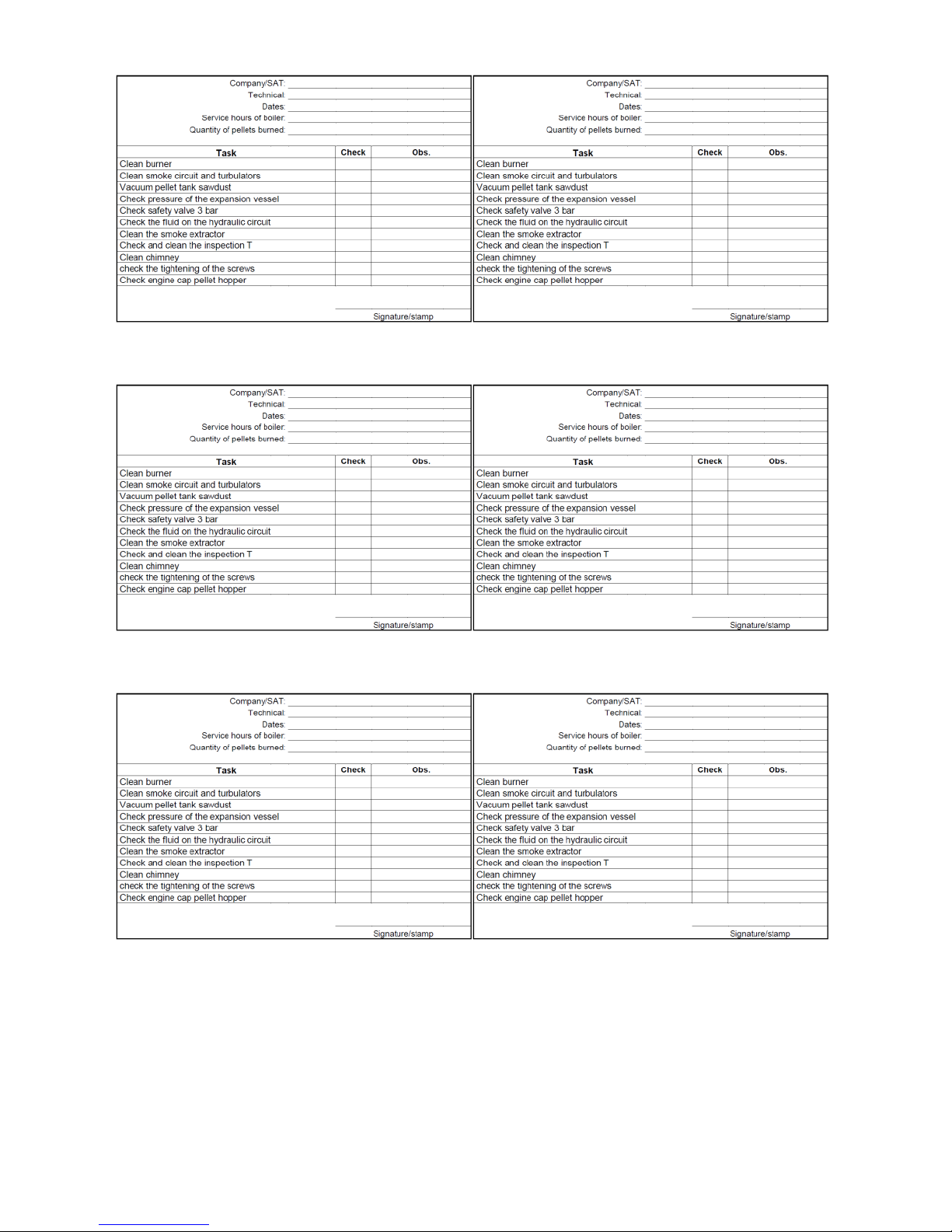
17. Maintenance Plan and Log
To ensure the proper operation of the unit, maintenance operations must be
performed, as described in Chapter 10 of this Instruction Manual or in the Maintenance
and Cleaning Guide. There are specific maintenance tasks that must be performed by
authorised technicians only. Please contact the person responsible for installing the
unit. To make sure the warranty remains valid, the maintenance operations performed
on this unit must comply with the frequency requirement specified in the manual, and
the service technician must fill and sign the maintenance log.
Client data:
Name:
Address:
Telephone:
Model:
Serial number:
74

75
76
77
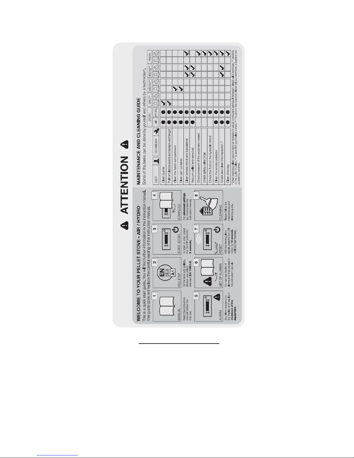
18. Maintenance Guide Label
Figure 60 – Maintenance guide label
Note: The safety warnings sticker label is attached from factory to the unit’s pellet lid,
in the Portuguese language. Attached to the manual you will find other language
versions of the sticker labels (Spanish, English, French and Italian). If necessary,
remove the Portuguese language label and replace it with the label in your country’s
language.

78
19. Electrical Diagram of the Free Standing Fire Unit
Figure 61 – Electrical diagram
20. End of life of a pellet insert
Approximately 90% of the materials used to manufacture these units are recyclable,
contributing towards a reduced environmental impact and a more sustainable planet.
End-of-life units should be processed by licensed waste operators. We recommend
contacting your local council to ensure the unit is collected and handled pursuant to
any legal requirements.
21. Warranty
This model requires that the unit is subject to start-up for the warranty to be to
activated. The start-up service can only be performed by technical services authorised
by the manufacturer. This is mandatory before the unit reaches 100 service hours. The
final user is responsible for any expenses related to the start-up service.

79
21.1. Warranty general conditions
1. Company name of the Manufacturer
SOLZAIMA S.A.
www.solzaima.pt
apoio.cliente@solzaima.pt
Address: Rua dos Outarelos; nº 111;
3750-362 Belazaima do Chão
Águeda - Portugal
This document does not constitute a voluntary warranty provided by SOLZAIMA S.A.
for any products manufactured and marketed by SOLZAIMA (hereinafter called
“Product(s)”). The purpose of this document is to provide the client with guidelines on
how to effectively activated the legal warranty that is standard to any consumer
Product (hereinafter “Warranty”). Naturally, this document does not impact any
warranty legal rights the Buyer may have, arising from the Product purchase contract.
2. Identification of the Warranted Product
The use of the warranty service is based on the assumption that, through the proper
means, the Client has previously sent the correct warranted Product information to
SOLZAIMA S.A. including the Product information as described on in the proof of
purchase and on the Product’s specification plate (model and serial number).
3. Warranty Conditions for the Product
3.1 A SOLZAIMA S.A. is liable towards the Buyer for the non-compliance of the Product
with the sale and purchase contract, within the following timeframes:
3.1.1 For 24 months from the Product’s delivery date, in case the Product is applied to
domestic use;
3.1.2 For 6 months from the Product’s delivery date, in case the Product is applied to
professional use;
3.2 To claim his rights and provided the deadline mentioned above is not exceeded, the
Buyer must denounce in writing to SOLZAIMA S.A. the Product’s non-compliance within

80
the following deadline:
3.2.1 Within 60 (sixty) days from the date the non-compliance was detected, in case
the Product is applied to domestic use;
3.2.2 Within 30 (thirty) days from the date the non-compliance was detected, in case
the Product is applied to professional use;
3.3 During the Warranty period specified under clause 3.1 above (to make sure the
Warranty is valid), any Product servicing operations must be exclusively performed by
the manufacturer’s technical services representative. All servicing under the scope of
this Warranty shall be performed from Monday to Friday within the working hours and
calendar legally established in each region.
3.4 Any service request must be sent to SOLZAIMA S.A. Customer Service via the
following email: apoio.cliente@solzaima.pt. Upon the technical servicing of the Product,
the Buyer must provide the technician with a document certifying the Product is in the
Warranty Period, namely the proof of purchase or other document supporting the
purchase. In any case, the document certifying that the Product is in the Warranty
Period must include the identification of the Product (as per clause 2 above) and the
date of purchase Alternatively, and to make the Product Warranty valid, the Client may
provide the PSR - the certifying document of the unit start-up (when applicable).
3.5 The Product must be installed by a specialized technician, qualified to install the
Product in compliance with the regulations applicable in the Client's geography, namely
those regarding the chimney, as well as other applicable regulations concerning water
supply, power supply and/or other utilities related to the use of the equipment or
sector, as described in the Instruction Manual. This Warranty shall be void in case of
non-compliance of the Product installation with the manufacturer’s specifications
and/or any applicable law in force. Should be Product be installed on the exterior of a
building, it must be protected from weather conditions, namely rain and wind. In this
case, it may be necessary to protect the unit with a cabinet or a protection box
properly ventilated.
3.6 The units cannot be installed in locations with chemicals agents in the atmosphere,
in saline or high humidity environments. The combination of these agents with oxygen
(air) may cause the quick corrosion of the combustion chamber to . In these

81
environments, it is recommended that the units are protected with proper anticorrosion
products, specially between periods of usage. We recommend the application of
graphite wax specific for high temperatures to lubricate and protect the unit from
corrosion.
3.7 For the equipments that use pellets, in addition to the daily and weekly
maintenance procedures described in the Instruction Manual, it is also mandatory to
clean the interior of the unit, as well as the fume exhaust chimney. These operations
should be performed at every 600-800 kg of used pellets for Free Standing Fire units
(air and water models) and Compact Boilers, and at every 2000-3000 kg of used
pellets for Automatic Boilers. If the used quantity of pellets is under these Figures, at
least a thorough preventive maintenance operation must be performed annually.
3.8 The Buyer is responsible for the execution of the periodic maintenance operations,
as set forth in the Product’s instruction and handling manuals provided with the unit.
When requested, a proof of maintenance must be produced, which includes the
technical report from the entity responsible for executing such procedures or,
alternatively, the filled in maintenance log provided in the corresponding section of the
instruction manual.
3.9 To avoid damages to the equipment due to overpressure, safety measures must be
taken during the installation of the unit, namely by installing pressure safety valves or
thermal safety valves, as applicable, as well as an expansion vase suited to the size of
the installation and operating properly. Please note: The above mentioned valves must
have a pressure rating equal or less than the pressure supported by the equipment. No
cutting valve must exist between the equipment and respective safety valve. A
thorough preventive maintenance plan must be in place to ensure the proper operation
of all the safety mechanisms. Regardless of the type of equipment, every safety valve
must be directed to siphoned drainage to prevent damages to the house caused by
water discharges. The Product’s Warranty does not include damages caused by the lack
of a piping system for the water discharging from such valve.
3.10 To prevent damages to the equipment and attached pipes due to galvanic
corrosion, we recommend using dielectric separators to connect the equipment to the
metallic pipes, since the applied materials may have components that enhance this
type of corrosion. The Product’s Warranty does not include damages caused by failure
to use the dielectric separators mentioned above.

82
3.11 The water or thermal fluid used for the heating system (water models of Free
Standing Fire units, Boilers, Central Heating Stoves, etc.) must comply with the
requirements of the applicable law, in addition to ensuring the following physical and
chemical properties: absence of solid suspended particles; low conductivity level;
residual hardness within 5 to 7 French degrees; neutral pH, close to 7; low
concentration of chloride and iron; and absence of air inlets by draught, or other inlets.
In case the installation promotes automatic water make-up, this system must
accommodate an upstream preventive treatment system consisting of filtration,
decalcification and preventive dosage of polyphosphates (encrustation and corrosion),
as well as a degassing step, if necessary. In the event any of these indicators show
figures different from the recommended values, the Warranty shall be void.
3.12 Except in cases expressly provided by law, a servicing operation performed during
the Warranty period does not renew the Product’s Warranty period. The rights arising
from the Warranty are not transferable to the Buyer of the Product.
3.13 The equipment must be installed in locations with easy access that present no risk
for the technicians. The Buyer is responsible to provide full access to the equipment for
servicing, and any related costs shall be paid by the Buyer.
3.14 The Warranty is valid for the Products and equipment sold by SOLZAIMA S.A. only
and exclusively within the geographic area and territory in the country where the
Product was sold by SOLZAIMA S.A..
4. Circumstances not covered by the Warranty
The following items are excluded from the Warranty coverage. The Buyer is responsible
for the total repair cost of:
4.1. Maintenance operations, Product adjustments, start-up procedures, cleaning,
clearing errors or anomalies not related to faulty components and battery replacement;
4.2. Components in direct contact with fire, namely: vermiculite brackets, deflecting or
protection plates, vermiculite, rope gaskets, burners, ash drawers, wood collectors,
smoke dampers, ash grates that will wear in compliance with its handling conditions.
Paint degradation, as well as corrosion caused by paint degradation, due to fuel

83
overload, open drawer usage or excessive extraction from the installation chimney.
For units operating on pellets, the lighting resistors are wearing parts, and for that
reason their warranty is limited to 6 months. Glass break due to improper handling or
any other reason not related to any fault in the product;
4.3. Components considered wearing parts, namely bearings and brass bearings;
4.4. Faulty components which are external to the Product and may affect its proper
operation, as well as material damages or others (e.g. roof tiles, roofs, waterproofed
coverings, piping, or personal damages) due to inadequate handling of materials during
the installation, non-compliance with the product’s installation rules, non-compliance
with the applicable laws or non-compliance with the rules of the trade, namely the use
of piping suited for the usage temperature and the use of expansion vessels, nonreturn valves, safety valves, anti-condensation valves, etc.;
4.5. Products whose operation has been affected by failures or deficiencies of external
components or by faulty sizing;
4.6. Defects caused by using as replacement parts accessories other than those
specified by SOLZAIMA S.A.;
4.7. Defects caused by non-fulfilment of the instructions for the installation, use and
operation, or usage not complying with the Product’s intended use, or even unusual
weather conditions, irregular operating conditions, overload or inadequate maintenance
or cleaning operations;
4.8. Products that have been modified or handled by people other than the
manufacturer’s service team and without explicit authorisation from SOLZAIMA S.A.;
4.9. Failures caused by external factors (rodents, birds, spiders, etc.), atmospheric
and/or geological phenomena (earthquakes, storms, frost, lightning, rain, etc.),
humidity aggressive environments (e.g. Proximity to the sea or river) as well as
failures resulting from excessive water pressure, inadequate electric connections,
(voltage with variations 10% higher than the nominal value of 230V), inadequate
circuit pressure or supply, acts of vandalism, urban riots and armed conflicts of any
kind, and derivatives;

84
4.10. The failure to use the fuel recommended by the manufacturer is a condition for
warranty exclusion;
Explanatory note: For equipments operating on pellets, the fuel in use must be certified
in accordance with EN 14961-2 standard, grade A1. Also, before buying large amounts
of fuel, please check the fuel to check it behaves as expected.
For wood operating equipments, the wood humidity content must be less than 20 %.
4.11. Evidence of corrosion, caused by a faulty installation or the usage of fuel other
than virgin wood (such as pallets or wood impregnated with paint, varnish, salt or
other components) contributing to the equipment’s rapid degradation, particularly the
combustion chamber;
4.12. Products, accessories or components damaged during transportation or
installation;
4.13. Cleaning operations executed on the equipment or its components, resulting from
condensation, fuel quality, bad adjustments or other circumstances arising from the
installation area. Also, the warranty service excludes interventions to decalcify the
Product (to eliminate the lime scale or other products deposited inside the equipment
and produced by the supplied water quality). Equally excluded are the warranty
services to vent the air in the circuit or unblock the circulating pumps.
4.14. The installation of the equipment supplied by SOLZAIMA S.A. must enable its
easy removal, as well as provide access points to the mechanical, hydraulic and
electronic components of the equipment and the installation. When the installation
does not allow for the immediate and safe access to the equipment, the additional
costs regarding access and safety will be paid by the Buyer. The cost of disassembling
and assembling boxes of plasterboards or masonry walls, isolation or other elements,
such as chimneys and hydraulic connections preventing free access to the Product (if
the Product is installed inside a plasterboard box, masonry wall or other dedicated
area, it must comply with the dimensions and properties indicated in the instruction
and use manual provided with the unit).
4.15. Household calls to provide information regarding the use of the heating system
and programming and/or reprogramming the adjustment and control elements, such
as thermostats, gauges, timers, etc.;

85
4.16. Fuel adjustment interventions in pellet operating equipment, cleaning, water leak
detection in the equipment’s external piping, damages caused by cleaning the machine
or the gas exhaust chimney;
4.17. Emergency interventions not included under the warranty service, i.e., during the
weekend and on holidays, since these are special interventions not included in the
warranty and therefore have an additional cost, based on a price list. These shall be
executed exclusively upon request from the Buyer and according to booking
availability.
5. Warranty Inclusion
SOLZAIMA S.A. will the Product, free of charge to the Buyer, any defects on the
Product that are covered by the warranty. The replaced Products or Components will
become the property of SOLZAIMA S.A.
6. SOLZAIMA S.A.’s responsibility
Without prejudice to the relevant legal provisions, SOLZAIMA S.A.’s responsibility
regarding the warranty is limited to the dispositions of the warranty conditions.
7. Price list for services executed outside the scope of the warranty
The interventions executed outside the scope of the warranty are subject to the current
price list;
8. Administrative Expenses
For invoices related to services executed and not paid within the specified due date,
late-payment fees will apply at the maximum legal rate.
9. Competent Court
The Parties agree that the settlement of any dispute arising from the sales purchase
contract of the Products covered by the Warranty shall be the competence of the Court
of Águeda, expressly waiving any other jurisdiction.

86
22. Annexes
22.1. Flow chart
Lighting

87

88
Disabling

89
22.2. Statement of Performance
DECLARAÇÃO DE DESEMPENHO | DECLARACIÓN PRESTACIONES | DECLARATION OF PERFORMANCE | DÉCLARATION DE
PERFORMANCE
Nº DD-037
1. Código de identificação único do produto-tipo | Código de identificación único del tipo de producto | Unique
identification code of the product type | Le code d'identification unique du type de produit | Codice unico di
identificazione del tipo di prodotto
FIRE 9KW – EAN 05600990442528
EARTH 9KW – EAN 05600990445185
WIND 9KW – EAN 05600990445437
2. Número do tipo, lote ou série do produto | Número de tipo, lote o serie del producto |Number of type, batch or
serial product | Nombre de type, de lot ou de série du produit |Numero di tipo, di lotto, di serie del prodotto
(VER CONTRACAPA)
3. Utilização prevista | Uso previsto | Intended use | Utilisation prévue | Destinazione d’uso
AQUECIMENTO DE EDIFÍCIOS DE HABITAÇÃO | CALEFACCIÓN DE EDIFICIOS RESIDENCIALES | HEATING OF RESIDENTIAL
BUILDINGS | CHAUFFAGE DE BATIMENTS RESIDENTIELS |RISCALDAMENTO DEGLI EDIFICI RESIDENZIALI
4. Nome, designação comercial registada e endereço de contacto do fabricante | Nombre, marca registrada y la
dirección de contacto de lo fabricante | Name, registered trade name and contact address of the manufacturer |
Nom, marque déposée et l’adresse de contact du fabricant | Nome, denominazione commercial registrata e indirizzo
del construtore
Solzaima
atendimento@solzaima.pt
Fabricado na UE
5. Sistema de avaliação e verificação da regularidade do desempenho do produto | Sistema de evaluación y
verificación de constancia de las prestaciones del | System of assessment and verification of constancy of
performance of the product | Système d’évaluation et de vérification de la Constance des performances du produit |
Sistema di valutazione e verifica della costanza della prestazione del prodotto
SISTEMA 3
6. Norma Harmonizada | Estandár armonizado | Harmonized standard | Norme harmoisée | Standard armonizatta
EN 14785
7. Nome e número de identificação do organismo notificado | Nombre y número de identificación del organismo
notificado | Name and identification number of the notified body | Nom et numéro d’identification de l’organisme
notifié | Nome e numero di identificazione dell’organismo notificato
TÜV RHEINLAND ENERGIE UND UMWELT GMBH
NB: 2456
8. Relatório de ensaio | Informe de la prueba | Test report | Rapport d’essai | Rapporto di prova
K18082016T1

90
9. Desempenho declarado | Desempeño declarado | Declared performance | Performance déclarée | Dichiarazione di
prestazione
Características essenciais |
Características esenciales |
Essencial characteristics |
Caractéristiques essentielles |
Caratteristiche essenziali
Desempenho | Desempeño
| Performance |
Prestazione
Especificações técnicas
harmonizadas |
Especificaciones técnicas
armonizadas |Harmonized
technical specifications |
Spécifications techniques
harmonisées | Specifiche
tecniche armonizzate
Segurança contra incêndio|Seguridad
contra incêndios|Fire safety|Sécurité
incendie | Sicurezza antincendio
OK. De acordo com relatório
de ensaio|De acuerdo com
informe de la
prueba|According to the test
report|Selons le rapport
d’essai | Secondo i rapporto
di prova K18082016T1
De acordo com os
requisitos|De acuerdo con
los requisitos|According to
the requirements|Selons les
exigences| Secondo i
requisiti 4.2, 4.3, 4.7, 4.8,
4.10, 4.11, 5.1, 5.3, 5.4,
5.5, 5.8 (EN14785)
Emissão de produtos da combustão|La
emisión de produtos de
combustión|Emission of combustion
products|Emission des produits de
combustion |Emissione dei prodotti di
combustione
OK. Caudal térmico
nominal|Caudal térmico
nominal|Nominal heat
output|Le débit calorifique
nominal|Nominal heat output
| Flusso termico nominale –
CO:0,01%
Caudal térmico
nominal|Caudal térmico
nominal|Nominal heat
output|Le débit calorifique
nominal|Nominal heat output
| Flusso termico nominale –
CO<0,04%
OK. Caudal térmico
reduzido|Flujo térmico
reducido|Reduced thermal
flow|Flux thermique réduit |
Flusso termico ridotto –CO:
0,035%
Caudal térmico
reduzido|Flujo térmico
reducido|Reduced thermal
flow|Flux thermique réduit |
Flusso termico ridotto –
CO<0,06%
Libertação de substâncias
perigosas|Emisión de sustancias
peligrosas|Release of dangerous
substances|Dégagement de
substances| Rilascio di sostanze
pericolose
OK. De acordo com relatório
de ensaio|De acuerdo com
informe de la
prueba|According to the test
report|Selons le rapport
d’essai | Secondo i rapporto
di prova K18082016T1
De acordo com o Anexo ZA.1
(EN14785)|De acuerdo con
lo Anexo ZA.1
(EN14785)|According to the
Annex ZA.1
(EN14785)|Selons le Annexe
ZA.1 (EN14785)| Secondo
l’allegato ZA.1 (EN14785)
Temperatura de superfície|Temperatura
de la superfície|Surface temperature|La
température de surface | Temperatura
superficiale
OK. De acordo com relatório
de ensaio|De acuerdo com
informe de la
prueba|According to the test
report|Selons le rapport
d’essai | Secondo i rapporto
di prova K18082016T1
De acordo com os
requisitos|De acuerdo con
los requisitos|According to
the requirements|Selons les
exigences| Secondo i
requisiti 4.2, 4.13, 5.1, 5.2,
5.4, 5.5 (EN14785)
Segurança eléctrica|Seguridad
eléctrica|Electrical safety|Sécurité
électrique l sicurezza elettrica
OK. De acordo com relatório
de ensaio|De acuerdo com
informe de la
prueba|According to the test
report|Selons le rapport
d’essai | Secondo i rapporto
di prova K18082016T1
De acordo com os
requisitos|De acuerdo con
los requisitos|According to
the requirements|Selons les
exigences |Secondo i
requisiti 5.9 (EN14785)
Aptidão para ser limpo|Capacidad para
ser limpiado|Ability to be
cleaned|Possibilité d’être nettoyé |
Capacità di essere puliti
OK. De acordo com relatório
de ensaio|De acuerdo com
informe de la
prueba|According to the test
report|Selons er apport
d’essai | Secondo i rapporto
di prova K18082016T1
De acordo com os
requisitos|De acuerdo con
los requisitos|According to
the requirements|Selons les
exigences |Secondo i
requisiti 4.5, 4.6, 4.10, 4.12
(EN14785)
Temperatura dos gases de
combustão|Temperatura de los gases
de combustión|Temperature of the flue
gas|Température du gaz de fumée
|Temperatura dato fumi
OK.
154ºC
De acordo com os
requisitos|De acuerdo con
los requisitos|According to
the requirements|Selons les
exigences |Secondo i
requisiti 6.2 (EN14785)
Resistência mecânica|Resistencia
mecânica|Mechanical
strength|résistance | Resistenza
meccanico
OK. De acordo com relatório
de ensaio|De acuerdo com
informe de la
prueba|According to the test
De acordo com os
requisitos|De acuerdo con
los requisitos|According to
the requirements|Selons les

91
report|Selons le rapport
d’essai | Secondo i rapporto
di prova K18082016T1
A cada 10 m de conduta de
fumos deve ser colocado um
suporte de carga| cada 10 m
de la salida de humos se debe
colocar un soporte de
carga|every 10 m of the flue
should be placed a load
support|tous les 10 m de
conduit de fumée doit être
placé un support de
charge|ogni 10 m della canna
fumaria deve essere posto un
supporto di carico
exigences |Secondo i
requisiti 4.2, 4.3(EN14785)
Potência térmica|Potencia
térmica|Thermic output|Puissance
thérmique|Potenza termico
OK.
8,3 KW
De acordo com os
requisitos|De acuerdo con
los requisitos|According to
the requirements|Selons les
exigences |Secondo i
requisiti 6.1, 6.4 – 6.10
(EN14785)
Rendimento energético|Eficiencia
energética|Energy efficiency|L’efficacité
énergétique |Efficienza energetica
OK.
90,1%
≥ 75% para potência
térmica nominal|de potencia
térmica nominal|for rated
termal input|Pour puissance
thermique nominale|di
potenza termica nominale
OK.
95,94%
≥ 70% para potência
térmica reduzida|la
reducción térmica|to reduced
termal|à la réduction
thermique | di potenza
térmica ridotto
Durabilidade | Durabilidad | Durability
| Durabilité | Durabilità
OK. De acordo com relatório
de ensaio|De acuerdo com
informe de la
prueba|According to the test
report|Selons le rapport
d’essai | Secondo i rapporto
di prova K18082016T1
De acordo com os
requisitos|De acuerdo con
los requisitos|According to
the requirements|Selons les
exigences |Secondo i
requisiti 4.2 (EN14785)
10. O desempenho do produto declarado nos pontos 1 e 2 é conforme com o desempenho declarado no ponto 9. A
presente declaração de desempenho é emitida sob exclusiva responsabilidade do fabricante identificado no ponto 4.
| El funcionamiento del producto se indica en los puntos 1 y 2 es compatible con las prestaciones declaradas en el
punto 9. La presente declaración se expide bajo la exclusiva responsabilidad del fabricante identificado en lo punto
4. | Performance of the product stated in points 1 and 2 is consistent with the declared performance in point 9. This
declaration of performance is issued under the sole responsibility of the manufacturer identified in point 4. | Les
performances du produit indiqué dans les points 1 et 2 est compatible avec les performances declares au point 9.
Cette declaration de performance est établie sous la seule responsabilité du fabricant identifié dans le point 4.
Portugal, 08/07/2016
 Loading...