

Page 1

Solwise
Set-up instructions for
Solwise SSR725
SDSL Router
Ltd
.
Revision 1.33
October 28 2003
Page 2

Chapter 1. Introduction Solwise SSR725 SDSL Ethernet Router User’s Guide
Notification is hereby given that Solwise Ltd. reserves the right to modify, change, update or revise this
document from time to time as required without the prior obligation to notify any person, company or
organization. Further, Solwise makes no warranty or representation, either express or implied, with
respect to merchantability, or fitness of its products for a particular purpose.
Solwise
13/15 Springfield Way
Anlaby
Hull HU10 6RJ
UK
Tel 0845 458 4558 (local rate)
Fax 0845 458 4559
Tech Support Tel 0845 1921320
SBV 1100
Email sales@solwise.co.uk
Http www.solwise.co.uk
Ltd.
Copyright
All rights reserved. No part of this document may be reproduced in any form or by any means
without written permission from the product manufacturer.
Changes are periodically made to the information in this document. They will be incorporated in
subsequent editions. The product manufacturer may take improvement and/or changes in the
product described in this document at any time.
FCC compliance
This equipment complies with Part 68 of the FCC Rules. On this equipment is a label that contains,
among other information, the FCC registration number and Ringer Equivalence Number (REN) for this
equipment. You must, upon request, provide this information to your telephone company.
If your telephone equipment causes harm to the telephone network, the Telephone Company may
discontinue your service temporarily. If possible, they will notify in advance. But, if advance notice isn’t
practical, you will be notified as soon as possible. You will be informed of your right to file a complaint
with the FCC.
Your telephone company may make changes in its facilities, equipment, operations, or procedures
that could affect proper operation of your equipment. If they do, you will be notified in advance to give
you an opportunity to maintain uninterrupted telephone service. The FCC prohibits this equipment to
be connected to party lines or coin-telephone service.
In the event that this equipment should fail to operate properly, disconnect the equipment from the
phone line to determine if it is causing the problem. If the problem is with the equipment, discontinue
use and contact your dealer or vendor.
2
Page 3

Solwise SSR725 User’s Guide
DOC compliance information
NOTICE: The Canadian Department of Communications label identifies certified equipment. This
certification means that the equipment meets certain telecommunications network protective,
operational and safety requirements. The Department does not guarantee the equipment will operate
to the user’s satisfaction.
Before installing this equipment, users ensure that it is permissible to be connected to the facilities of
the local Telecommunications Company. The equipment must also be installed using an acceptable
method of connection. The customer should be aware that compliance with the above conditions
might not prevent degradation of service in some situations.
Repairs to certified equipment should be made by an authorized Canadian maintenance facility
designated by the supplier. Any repairs or alterations made by the user to this equipment, or
equipment malfunctions, may give the telecommunications company cause to request the user to
disconnect the equipment.
Users should ensure for their own protection that the electrical ground connections of the power utility,
telephone lines and internal metallic water pipe system, if present, are connected together. This
precaution may be particularly important in rural areas.
CAUTION: Users should not attempt to make such connections themselves, but should contact the
appropriate electric inspection authority, or electrician, as appropriate.
NOTICE: The Load Number (LN) assigned to each terminal device denotes the percentage of the
total load to be connected to a telephone loop which is used by the device, to prevent overloading.
The termination on a loop may consist of any combination of devices subject only to the requirement
that the sum of the Load Numbers of all the devices does not exceed 100.
European CTR 21 compliance
The equipment has been approved in accordance with Council Decision 98/482/EC for pan-European
single terminal connection to the public switched telephone network (PSTN). However, due to
differences between the individual PSTNs provided in different countries, the approval does not, of
itself, give an unconditional assurance of successful operation on every PSTN network termination
point. In the event of problem, you should contact your equipment supplier in the first instance.
3
Page 4

Page 5

Solwise SSR725 SDSL Ethernet Router User’s Guide Chapter 1. Introduction
Table of Contents
1 Introduction..........................................................7
1.1 Overview.....................................................................7
1.2 Features and Compatibility ........................................7
1.3 What’s in the package?..............................................8
1.4 Front Panel .................................................................8
1.5 Rear Panel.................................................................. 9
2 Connecting to your network and line.................10
3 Setting up TCP/IP on your computer ................11
3.1 Installing TCP protocol on your PC..........................11
3.2 Setting up TCP/IP protocol on your Mac.................15
4 PPPoA Router NAT configuration.....................18
4.1 Setting up a basic NAT router configuration............19
5 How to…............................................................43
5.1 How to enter Command Line Interface mode .........43
5.1.1 Telnet...............................................................43
5.1.2 Using terminal program via serial
console port ..............................................................43
5.1.3 Basic CLI syntax .............................................46
5.2 Altering the LAN IP address of the router................48
5.3 Set-up port forwarding..............................................49
5.4 Configuring the ‘Security Interface’ to allow
Netmeeting ......................................................................54
5.5 Configuring the ‘Security Interface’ to allow
ftp 58
5.6 Firewall Features......................................................59
5.6.1 Intrusion Detection ..........................................59
5.6.2 Packet Filtering................................................60
5.7 Using your 7x5 Router with fixed IP address ..........67
5.8 Enabling DHCP Server Mode ..................................71
5.9 Altering the configuration user name and
password .........................................................................75
6 Firmware Upgrade ............................................78
6.1 Upgrading to a new firmware version using
http 78
6.1.1 When things go wrong! ...................................80
5
Page 6

Chapter 1. Introduction Solwise SSR725 SDSL Ethernet Router User’s Guide
6.2 Using xmodem to upload the firmware files ............81
6.2.1 Loading a new bootcode bin firmware
file 81
6.2.2 Loading a new main bin firmware file.............90
7 Appendix A Product Specifications.................100
8 Appendix B Government compliance
notices ..........................................................103
9 Appendix C IP Addresses, Network
Masks, and Subnets.....................................105
9.1 IP Addresses ..........................................................105
9.1.1 Structure of an IP address............................105
9.1.2 Network classes ............................................106
9.2 Subnet masks.........................................................106
10 Appendix D Binary Numbers...........................109
10.1 Binary Numbers ....................................................109
10.1.1 Bits and bytes..............................................109
11 Appendix E Glossary.......................................111
6
Page 7

1 Introduction
1.1 Overview
The SSR SDSL Router features multi-mode SDSL technology that
provides a downstream rate of up to 8M bps over existing copper
wire lines, which is more than 100 times faster than a traditional 56K
analogue modem. The 725 model can be connected to your PC or
LAN through the 10/100Base-T Ethernet interface and includes a 4port 10/100 switching hub. The 705 model can also be connected to
your PC or LAN but has a single 10/100Base-T port only.
It is designed to meet both the needs of single user, and multiple
users at small office and home office who want fast Internet access.
A wide variety of features and interoperability offer scalability and
flexibility for all the applications
1.2 Features and Compatibility
The SSR series Router provides the following features:
• Full rate maximum2.3Mbps speed (G.SHDSL) connection.
• Simple configuration through HTTP and TFTP and configuration file.
• IEEE 802.3 & 802.3u over UTP (10/100Base-T) compliant
• Operation with up to 4.6Mbps downstream and upstream simultaneously enables
High-Speed access to Internet Service Provider (ISP) or corporate network
• Friendly GUI Configuration and Management software
• Supports G.SHDSL always-on
• Ongoing feature enhancements through TFTP download or upload of new firmware
and configuration files
• Supports multiple PVC up to 8 PVCs for RFC 1483 and ATM Forum UNI 3.0, 3.1 and
4.0 signaling for SVC
• Supports full VPI range (8 bits, 0-256) and VCI range (16 bits, 1-65535) over PVC. VPI
is limited to VPI 0 only over SVC.
• Enables end-to-end ATM support, which allows traffic management and QoS.
• Built-in DHCP server automatically assigns IP addresses to all workstations on your
LAN.
• All management and monitoring can be done through SNMP or Telnet session.
• Multi-mode SDSL technology supports ITU-T G.hs, G.dmt, G.lite and ANSI T1.413
issue 2 to provide interoperability with most DSLAM equipment.
• ATM (Asynchronous Transfer Mode) protocol allows the QoS(Quality of Service)
transmission over a network
7
Page 8

Chapter 1. Introduction Solwise SSR725 SDSL Ethernet Router User’s Guide
• Support for text-based console management over Telnet and serial connection,
Windows-GUI based, and via http.
• Support for remote configuration by your network administrator via IP network.
• Support IEEE 802.1d transparent bridging with spanning tree algorithm.
• Bridge filtering allows a network administrator to control the flow of packets across the
router
• NAT : let multiple users on the LAN share one Internet connection simultaneously
• Point-to-Point Protocol (PPP)
• RFC 1483 Link Protocol
• Password Authentication Protocol (PAP) and Challenge Handshake Authentication
Protocol (CHAP) security under PPP protocol
• IP routing support includes the RIP(Routing Information Protocol) which allows the
exchange of routing information on a TCP/IP network
• Flash memory for Software upgrade
• Status LEDs for easy monitoring and troubleshooting
• DNS relay: allows for automatic name resolution when no DNS information is
configured by the user.
1.3 What’s in the package?
One SDSL Router
One 9VDC Adapter
One RJ-11 Telephone Cable
One 10Base-T Ethernet straight-through Cable
One Software CD containing the User’s Guide and configuration software
All packages have been checked carefully for their completeness
and functionality before shipped. Please contact the place of
purchase if any of the above listed items are missing or damaged.
1.4 Front Panel
The SDSL Router has several status LEDs for diagnostics. You can
monitor the LEDs during operation. The following table shows the
SDSL Router status LEDs and identifies what each LED light
means.
8
Page 9

Solwise SSR725 SDSL Ethernet Router User’s Guide Chapter 1. Introduction
Function Behavior Definition
Dark Power off POWER
Light Power on
Flashing slowly SDSL training in progress DSL-LINK
Light SDSL link is establish and ready to transfer data
LAN-LINK/ACT
L1 L2 L3 L4
Dark Ethernet link absent or power off
Light Ethernet link present on appropriate port (green for
100Mbs, red for 10Mbs)
DSL-ACT Flashing Receiving data from SDSL link
1.5 Rear Panel
The rear panel of the SDSL Router consist of power jack, Console
Port connector, Ethernet connections and SDSL phone socket as
below:
SSR725:-
Function Definition
ON/OFF Power on/off switch
DC The power jack connects to 9VDC Adapter from wall outlet.
Console This is RS232C interface and use to management SDSL Router.
Uplink-OR-L4 Use this port to connect to a computer OR as an uplink to connect to
the LAN port of another hub
L3 L2 L1 10/100 Ethernet interface connect to PC.
DSL SDSL jack connect to DSL line from TelCo
9
Page 10

Chapter 2. Connecting to your network and line Solwise SSR725 SDSL Ethernet Router User’s Guide
2 Connecting to your network and line
LAN ports L1 to L4 on the SSR725 router are the type designed to be connected to directly to the port on a PC LAN card using a
standard cat5 LAN cable. If you wish to connect the router to another hub then you must use the connector marked ‘Uplink’ to connect to
a ‘normal’ port on the second hub. Please note that you can use either the Uplink port OR L4 but NOT both at the same time.
Use the supplied RJ11 phone cable to connect from the SDSL
socket on your router to your SDSL phone socket.
Connect the power jack from the power supply to the power socket
on the router and then plug the power supply into a suitable UK
power socket: The amber POWER LED on the front of the router
should light up.
Configuration can be carried out using the Command Line Interface
via Telnet (user name is ‘admin’ and password is ‘admin’ and
default IP address of the router is 192.168.7.1) or via a serial port
link to the 9 pin console port on the rear of the router (port settings
9600,8,1,n,no flowcontrol). Alternatively a more user friendly
configuration method is to use the built in http interface. To do this
all you need to do to be able to do is access the router through your
web browser running on any computer.
10
Page 11
Solwise SSR725 SDSL Ethernet Router User’s Guide Chapter 3. Setting up TCP/IP on your computer
3 Setting up TCP/IP on your computer
You first of all need to check the TCP/IP settings of your computer.
Please note that the author is assuming you are using MS Windows
(Win9x or 2K/XP) or Mac OS10; please make appropriate
allowances if using another operating system or platform such as
Linux. The default IP address of the SSR router is 192.168.7.1 on
subnet mask 255.255.255.0. In simple terms this means that, in
order for your computer to talk to the router, their IP address should
be in the range from 192.168.7.2 to 192.168.7.254. If you already
use TCP as your default network protocol and you don’t use IP
settings in the required range then you will have to either
permanently alter the settings of your computers to suite or change
the default address of the router. If you wish to alter the settings of
all your computers to suite then it is probably best to ask the person
in charge of your network set-up to do this for you. If you want to
alter the router then you will have to temporarily change the settings
for your PC.
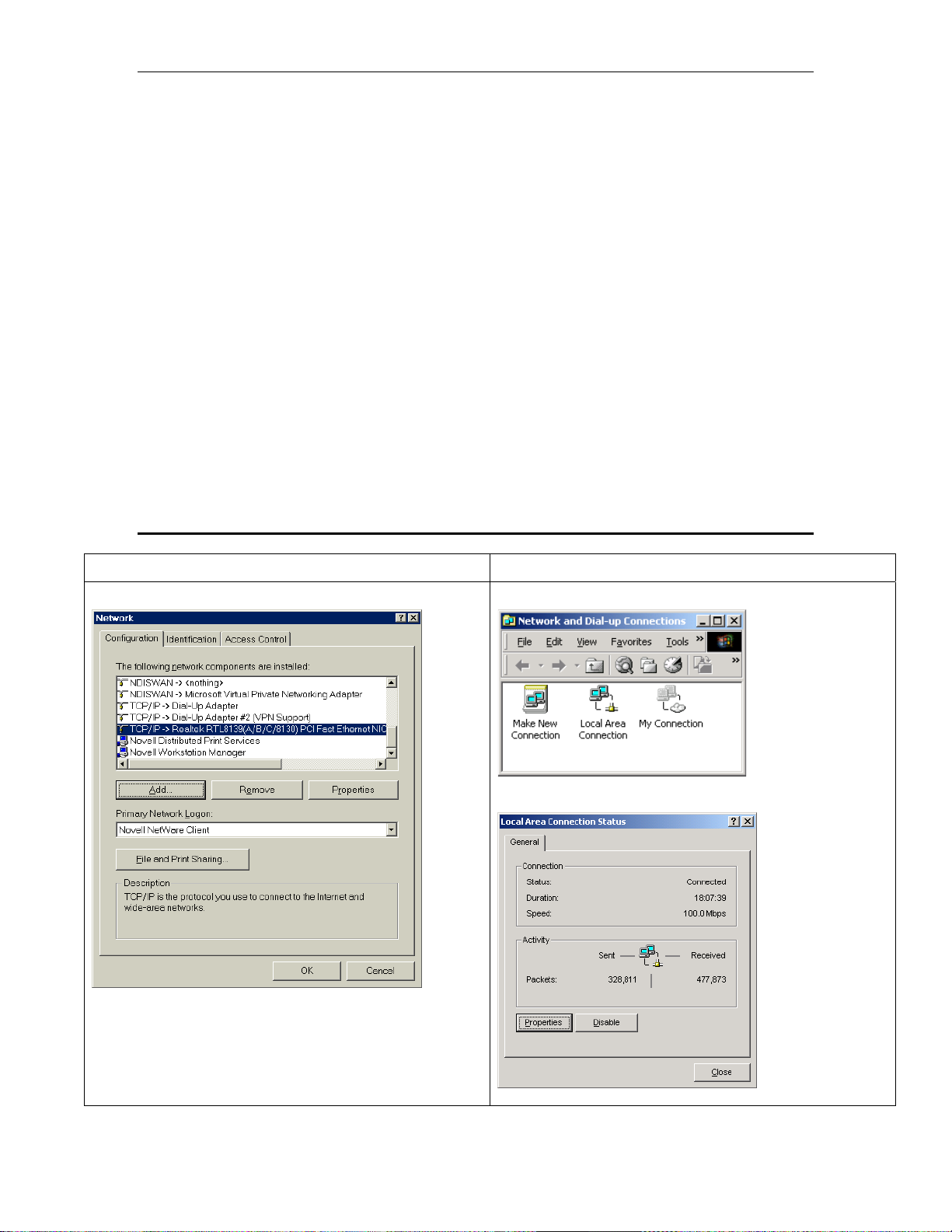
3.1 Installing TCP protocol on your PC
Win9x Win2K/XP
Go to Start/Settings/Control Panel/Network....
Go to Start/Settings/Network and Dialup Connections...
Click on ‘Local Area Connection’.
If you already see a line showing TCP/IP protocol such as
the example shown above then you can skip this section.
Otherwise click on Add, then select Protocol and then click
on Add.. again. Then on the Select Network Protocol
screen select Microsoft/TCP/IP...
11
Page 12

Chapter 3. Setting up TCP/IP on your computer Solwise SSR725 SDSL Ethernet Router User’s Guide
Click on OK and Windows will then add the protocol to your network setup.
Then on Properties..
If you already see a line showing TCP/IP protocol such as
the example shown above then you can skip this section.
Otherwise click on Install, then select Protocol and then
click on Add.
Then on the Select Network Protocol screen select
Microsoft/TCP/IP...
Click on OK and Windows will then add the protocol to
your network set-up.
12
Page 13

Solwise SSR725 SDSL Ethernet Router User’s Guide Chapter 3. Setting up TCP/IP on your computer
Scroll down the list of network settings until you find the
entry showing TCP/IP. There may be several such entries
(see example); the one you need is the entry associated
with your network card. Select it and then click on
Properties:
Go to your local network settings (Start/Settings/Network
and Dialup Connections/Local Area
Connection/Properties).
Scroll down the list of network settings until you find the
entry showing TCP/IP. Select it and then click on
Properties:
The first screen shows the IP Address for your PC. As
already explained, you need to ensure that each PC on
your LAN has an IP address which is both unique and
within the subnet range of the routers address e.g. in the
range 192.168.7.2 to 192.168.7.254 (assuming default IP
address for the router).
Next, for each PC you must enter a Gateway address. This
is the address of the router and tells your PC where to
send internet TCP requests:
As already explained, you need to ensure that each PC on
your LAN has an IP address which is both unique and
within the subnet range of the routers address e.g. in the
range 192.168.7.2 to 192.168.7.254 (assuming default IP
address for the router).
Now you need to enter the address of the router as the
default gateway.
13
Page 14

Chapter 3. Setting up TCP/IP on your computer Solwise SSR725 SDSL Ethernet Router User’s Guide
Finally you must set-up DNS Configuration on each PC:
Each PC MUST have the address for DNS entered in it’s
TCP setting. If your PC doesn’t have a DNS setting then it
will not be able to find any internet sites so it’s important
that you have this set correctly!
On the DNS Configuration screen you must Enable DNS
and then enter a Host name; this can be anything you like
– just a made up name will do!
Now you need to enter the DNS address.
Each PC MUST have the address for DNS entered in it’s
TCP setting. If your PC doesn’t have a DNS setting then it
will not be able to find any internet sites so it’s important
that you have this set correctly!
On the main TCP/IP Properties screen select ‘Use the
following DNS server addresses’.
Now you need to enter an address for the ‘Preferred DNS’.
Ideally you should get the DNS address to use from your
ISP (a list showing some of the common ISP DNS
addresses is given below). However, if you don’t know the
ISPs’ DNS address then you can temporarily use the
address 212.50.160.28.
Enter the DNS address for the preferred DNS (as shown
above).
Finally click on OK, then OK and then Close. The new
TCP/IP settings should take immediate effect.,
14
That’s all there is to the basic set-up.
Page 15

Solwise SSR725 SDSL Ethernet Router User’s Guide Chapter 3. Setting up TCP/IP on your computer
Ideally you should get the DNS address to use from your
ISP (a list of common addresses is given later). However, if
you don’t know the ISPs’ DNS address then you can
temporarily use the address 212.50.160.28. You need to
‘add’ the DNS address to the DNS list.
Finally click on OK and then OK from the main Network
menu.
Windows will now install the revised network settings;
please note that your original Windows installation CD
might be required. You should then reboot your PC.
That’s all there is to the basic set-up.
3.2 Setting up TCP/IP protocol on your Mac
Configuration of the router is done using your web browser but first
of all you need to ensure that the IP settings on computer are
correctly set to enable you to talk with the router. The default IP
address of the Asus router is 192.168.7.1 with netmask
255.255.255.0. This means your computers and other network
resources should have IP address’s in the range 192.168.7.2 to
192.168.7.254. First of all go to the Network set-up on your Mac
:
15
Page 16

Chapter 3. Setting up TCP/IP on your computer Solwise SSR725 SDSL Ethernet Router User’s Guide
Enter a suitable IP address (e.g. 192.168.7.2) and the netmask as
shown above and click on Apply Now.
Now enter the IP address of the router in ‘Router’ box.
16
Page 17

Solwise SSR725 SDSL Ethernet Router User’s Guide Chapter 3. Setting up TCP/IP on your computer
You also need to enter an address for your ‘Domain Name Server’.
Ideally you should get the DNS address to use from your ISP.
However, if you don’t know the ISPs’ DNS address then you can
temporarily use the address 212.50.160.23.
Add the DNS address to the Domain Name Server list.
That’s all you should have to do. Click on Apply Now and your new
settings should be set.
17
Page 18

Chapter 4. PPPoA Router NAT configuration Solwise SSR725 SDSL Ethernet Router User’s Guide
4 PPPoA Router NAT configuration
The easiest way to configure your router is via your web browser
accessing the html pages direct in the router. Please note that if
there is some reason why you cannot do configuration via a web
browser then you will have to use console management via the
WAN port of the router connected to the serial port of your PC and
then use the GUI application located on the software CD. To do this
you will need to use the 9 pin serial lead supplied. Details on how to
do configuration via the GUI software are given later in this guide.
To configure using your browser you must first of all must have
successfully installed TCP/IP protocol on your computer as detailed
above.
After checking your connections and TCP settings (see above) you
are ready to run your browser in order to configure the router.
Any browser can be used on any operating system: The
configuration screens are the same.
Note: If you are using Explorer on a PC then first
check that your browser is set to use LAN for internet
access. To do this in Explorer go to Tools/Internet
Options/Connections. Then check that the setting
‘Never dial a connection’ is selected. Then on the LAN
Settings screen nothing should be ticked.
Now start your browser and enter the address of the router on the
Address/URL line of your browser (192.168.7.1). The browser
should then load the start-up page from the router:
18
Page 19

Solwise SSR725 SDSL Ethernet Router User’s Guide Chapter 4. PPPoA Router NAT configuration
4.1 Setting up a basic NAT router configuration
Please note the following:
The default IP address for the 8.2 firmware is 192.168.7.1
The default configuration username and password are admin.
Now change the IP address of your PC to be on the same subnet
as the 725/705 with Virata 8.2 (e.g. 192.168.7.2).
Next, enter the address of the router in your browser address line
(i.e. 192.168.7.1)…
The main status page for the router should display.
19
Page 20

Chapter 4. PPPoA Router NAT configuration Solwise SSR725 SDSL Ethernet Router User’s Guide
First of all you are advised to clear the router configuration. To do
this goto System/Restart/Reset. To enter configuration, enter admin
for username and password…..
20
Page 21

Solwise SSR725 SDSL Ethernet Router User’s Guide Chapter 4. PPPoA Router NAT configuration
21
Page 22

Chapter 4. PPPoA Router NAT configuration Solwise SSR725 SDSL Ethernet Router User’s Guide
Select ‘Reset to factory default settings’ and then click on Restart….
22
Page 23

Solwise SSR725 SDSL Ethernet Router User’s Guide Chapter 4. PPPoA Router NAT configuration
Wait about 30 seconds for the router to reboot and the Status page
should reload…
23
Page 24

Chapter 4. PPPoA Router NAT configuration Solwise SSR725 SDSL Ethernet Router User’s Guide
Now goto Configuration/DSL Mode.
24
Page 25

Solwise SSR725 SDSL Ethernet Router User’s Guide Chapter 4. PPPoA Router NAT configuration
Select cpe-b (for UK Annex B DSL) and then click on Apply.
25
Page 26

Chapter 4. PPPoA Router NAT configuration Solwise SSR725 SDSL Ethernet Router User’s Guide
Now goto the Configuration/WAN Connections …
26
Page 27

Solwise SSR725 SDSL Ethernet Router User’s Guide Chapter 4. PPPoA Router NAT configuration
Delete and existing services shown…
27
Page 28

Chapter 4. PPPoA Router NAT configuration Solwise SSR725 SDSL Ethernet Router User’s Guide
28
Page 29
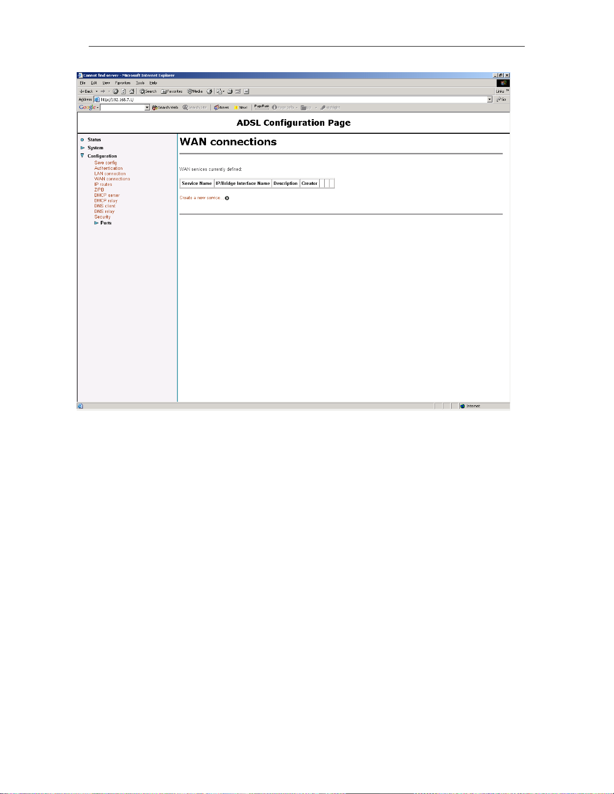
Solwise SSR725 SDSL Ethernet Router User’s Guide Chapter 4. PPPoA Router NAT configuration
Now you can add a new service so click on “Create a new service”.
29
Page 30
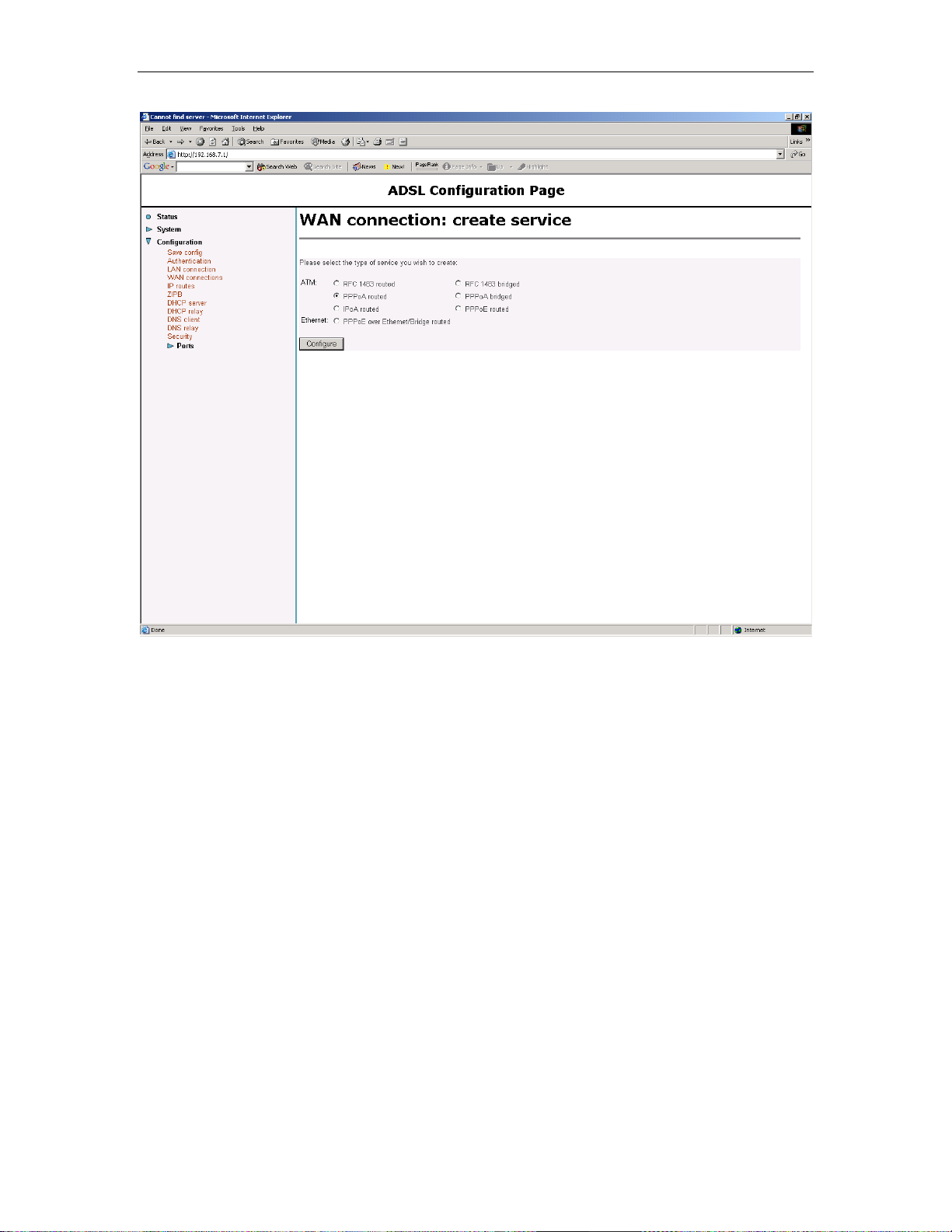
Chapter 4. PPPoA Router NAT configuration Solwise SSR725 SDSL Ethernet Router User’s Guide
Select PPPoA Routed and then click on Configure…
30
Page 31

Solwise SSR725 SDSL Ethernet Router User’s Guide Chapter 4. PPPoA Router NAT configuration
Enter the details required:
Put a name for the Description (maybe the name of your ISP).
Then put in the correct VPI/VCI values (for BT 0/38).
Tick the box Enable NAT.
If you are on a KC phone line then set LLC Header to on (for a BT
line leave this as off).
Then select CHAP and enter your login name and password as
supplied by your ISP. PLEASE NOTE – Even if your ISP doesn’t
provide a login password you MUST enter one (just make one up!).
Click on the Configure button…
31
Page 32

Chapter 4. PPPoA Router NAT configuration Solwise SSR725 SDSL Ethernet Router User’s Guide
Now goto Configuration/Security.
32
Page 33
Solwise SSR725 SDSL Ethernet Router User’s Guide Chapter 4. PPPoA Router NAT configuration
Click on Add interface..
33
Page 34

Chapter 4. PPPoA Router NAT configuration Solwise SSR725 SDSL Ethernet Router User’s Guide
Select the iplan as type internal and click on Apply.
34
Page 35

Solwise SSR725 SDSL Ethernet Router User’s Guide Chapter 4. PPPoA Router NAT configuration
Now goto Configuration/Save Config..
35
Page 36

Chapter 4. PPPoA Router NAT configuration Solwise SSR725 SDSL Ethernet Router User’s Guide
Save the configuration.
36
Page 37

Solwise SSR725 SDSL Ethernet Router User’s Guide Chapter 4. PPPoA Router NAT configuration
Wait for the “Saved information…” message.
Now goto System/Restart to reboot the router.
37
Page 38

Chapter 4. PPPoA Router NAT configuration Solwise SSR725 SDSL Ethernet Router User’s Guide
Wait for the router to restart…
38
Page 39

Solwise SSR725 SDSL Ethernet Router User’s Guide Chapter 4. PPPoA Router NAT configuration
The status page should display.
39
Page 40

Chapter 4. PPPoA Router NAT configuration Solwise SSR725 SDSL Ethernet Router User’s Guide
If you have the router connected to the ADSL service then, after a
while, the R1483 Port line should show a green tick (indicating
ADSL connection).
40
Page 41

Solwise SSR725 SDSL Ethernet Router User’s Guide Chapter 4. PPPoA Router NAT configuration
Now goto Show Statistics on the WAN interface entry on the bottom
of the status page (e.g. the one labeled kc in our example here).
41
Page 42

Chapter 4. PPPoA Router NAT configuration Solwise SSR725 SDSL Ethernet Router User’s Guide
If you have a valid login with your ISP then the IP address at the top
of the ppp-0 status page should be valid (i.e. NOT 0.0.0.0). If you do
NOT see a valid IP address (e.g. 0.0.0.0) then your router is not
correctly logged in with the ISP. In this case check the your login
name and password (see trouble shooting at the end of this
guide).
You can now connect the router to the rest of your network.
42
Page 43

Solwise SSR725 SDSL Ethernet Router User’s Guide Chapter 5. How to…
5 How to…
5.1 How to enter Command Line Interface mode
Although the majority of the most common set-up options can be
done via the web interfaces, some of the more complicated/less
common features can only be configured via the Command Line
Interface (CLI) mode. To access the CLI mode you can use either
Telnet via the LAN or use console programme via the serial port.
5.1.1 Telnet
To access the command line interface via Ethernet interface, you
can use TELNET to log in the Router from the local Ethernet
network using the Ethernet IP address that is assigned to your
SDSL Router. The Ethernet IP of the SDSL Router is by default set
to 192.168.7.1.
Select Start->Programs->MS-DOS Prompt.
Find the IP address of the Router’s Ethernet port. Then use
TELNET to login the Router. For example, TELNET 192.168.7.1 (in
the example below the IP of the router in our test was set to
192.168.0.11 – however you should use the correct IP address set
for your router).
You will see that a telnet dialog pops up asking for your
configuration Login name. By default this is ‘admin’. Then you need
the password which by default is also admin. Then the prompt
should be shown with a successful login.
Now you are ready to configure the Router by using command line
interface (CLI) commands.
5.1.2 Using terminal program via serial console port
A terminal can be connected directly to the Serial console port. This
requires the use of a terminal emulation software package such as
Microsoft HyperTerminal. By default setting, the Router is
configured to communicate at a baud rate of 9600. Any standard
43
Page 44
Chapter 5. How to… Solwise SSR725 SDSL Ethernet Router User’s Guide
terminal that supports baud rate of 9600 can be connected to the
Router’s console port. Please configure your serial port as:
BPS :9600
Data bits :8
Parity :None
Stop Bits :1
Flow Control :None
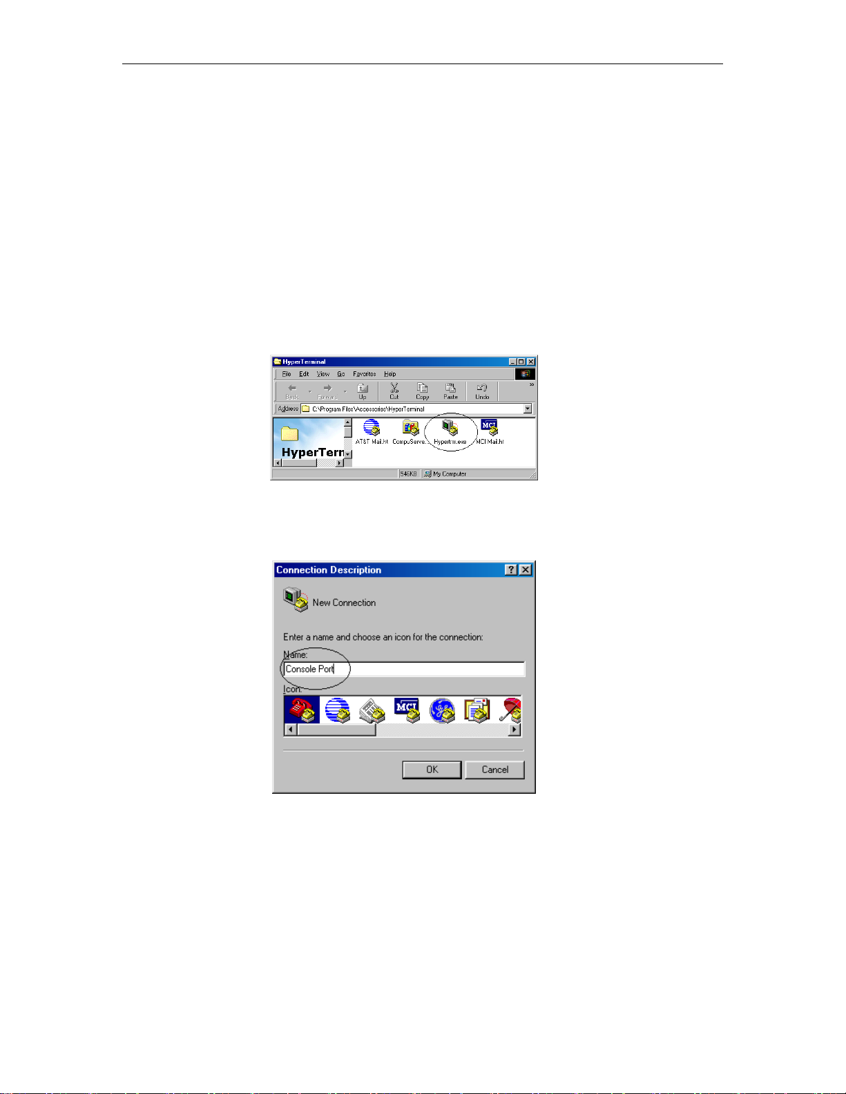
Then do the following steps to log on to the Router via Microsoft
HyperTerminal.
Select Start->Programs->Accessories->HyperTerminal
Enter a connection name and click OK
Select properly COM port and click OK
44
Page 45

Solwise SSR725 SDSL Ethernet Router User’s Guide Chapter 5. How to…
Enter the following parameters :
Bits per second 9600
Data bits 8
Parity None
Stop bits 1
Flow Control None
Then click OK
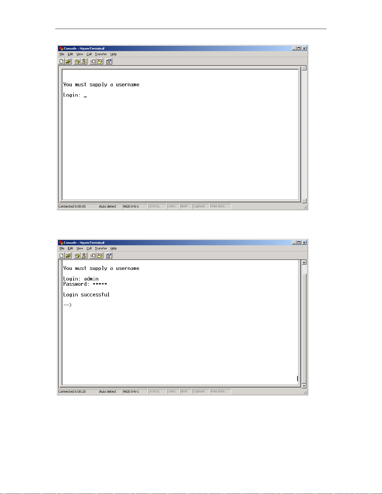
When the HyperTerminal window appears, you must press the
enter key several time to get the command prompt for the Router’s
command line interface.
45
Page 46
Chapter 5. How to… Solwise SSR725 SDSL Ethernet Router User’s Guide
You should then see the Login: prompt. By default this is ‘admin’.
Then you need the password which by default is also admin. Then
the prompt should be shown with a successful login.
5.1.3 Basic CLI syntax
46
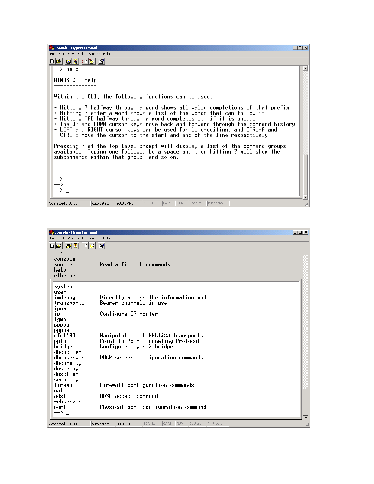
Now you are ready to configure the Router by using the command
line interface (CLI) commands.
If you type ‘help’ at the CLI prompt then the following instructions
are given.
Page 47
Solwise SSR725 SDSL Ethernet Router User’s Guide Chapter 5. How to…
This should explain the basic syntax used for command entry. So, if
you press ‘?’ the current commands are listed:
This shows the complete list of CLI commands.
47
Page 48

Chapter 5. How to… Solwise SSR725 SDSL Ethernet Router User’s Guide
To enter a command you just type the command in as simple text.
E.g. ‘system config save’ saves the configuration…
For full details of all the CLI commands please refer to the CLI
Reference Manual.
Remember, after doing any changes in CLI mode you must
enter the ‘system config save’ command to store your
settings. If you don’t do this then they may be lost after a power
down or restart.
5.2 Altering the LAN IP address of the router
If you want to alter the LAN address of the router then click on
“Configuration/LAN connection”:
48
Page 49

Solwise SSR725 SDSL Ethernet Router User’s Guide Chapter 5. How to…
5.3 Set-up port forwarding
Figure 1
Next change the LAN address and subnet to the required values
(note that the Secondary IP Address allows you to run a separate
LAN subnet range on the same port – useful if you want to
configure ports forwarding or firewall settings for a separate LAN).
Then click on Apply. Please note that, once you change the LAN
address you will then have to immediately change the IP address of
your PC so you can ‘see’ the router again.
Finally save the configuration and reset the router.
Goto Configuration/Security..
49
Page 50

Chapter 5. How to… Solwise SSR725 SDSL Ethernet Router User’s Guide
Under Security Interfaces click on Advanced NAT Configuration…
50
Page 51

Solwise SSR725 SDSL Ethernet Router User’s Guide Chapter 5. How to…
Then click on Add Reserved Mapping…
51
Page 52

Chapter 5. How to… Solwise SSR725 SDSL Ethernet Router User’s Guide
Now add the port mapping rule you require e.g. to forward the telnet
port to point to the LAN port of the router (so you can do remote
configuration using telnet) you should add 23/tcp…
52
Page 53

Solwise SSR725 SDSL Ethernet Router User’s Guide Chapter 5. How to…
Enter the new rule and click on Add Reserved Mapping..
53
Page 54

Chapter 5. How to… Solwise SSR725 SDSL Ethernet Router User’s Guide
You should now save the new settings (Configuration/Save config).
5.4 Configuring the ‘Security Interface’ to allow Netmeeting
Goto Configuration/Security..
54
Page 55

Solwise SSR725 SDSL Ethernet Router User’s Guide Chapter 5. How to…
Now click on ‘Security Trigger Configuration’ at the bottom of the
screen.
55
Page 56

Chapter 5. How to… Solwise SSR725 SDSL Ethernet Router User’s Guide
Now click on ‘New Trigger’..
56
Page 57
Solwise SSR725 SDSL Ethernet Router User’s Guide Chapter 5. How to…
The following settings are required for Netmeeting
Now click on apply..
57
Page 58

Chapter 5. How to… Solwise SSR725 SDSL Ethernet Router User’s Guide
If you are using the firewall then you must ensure that you setup
port filter rules to allow the netmeeting traffic to come through. In
this case, the ports that you will need to open up are:
More details on the security trigger commands are given in the CLI
manual.
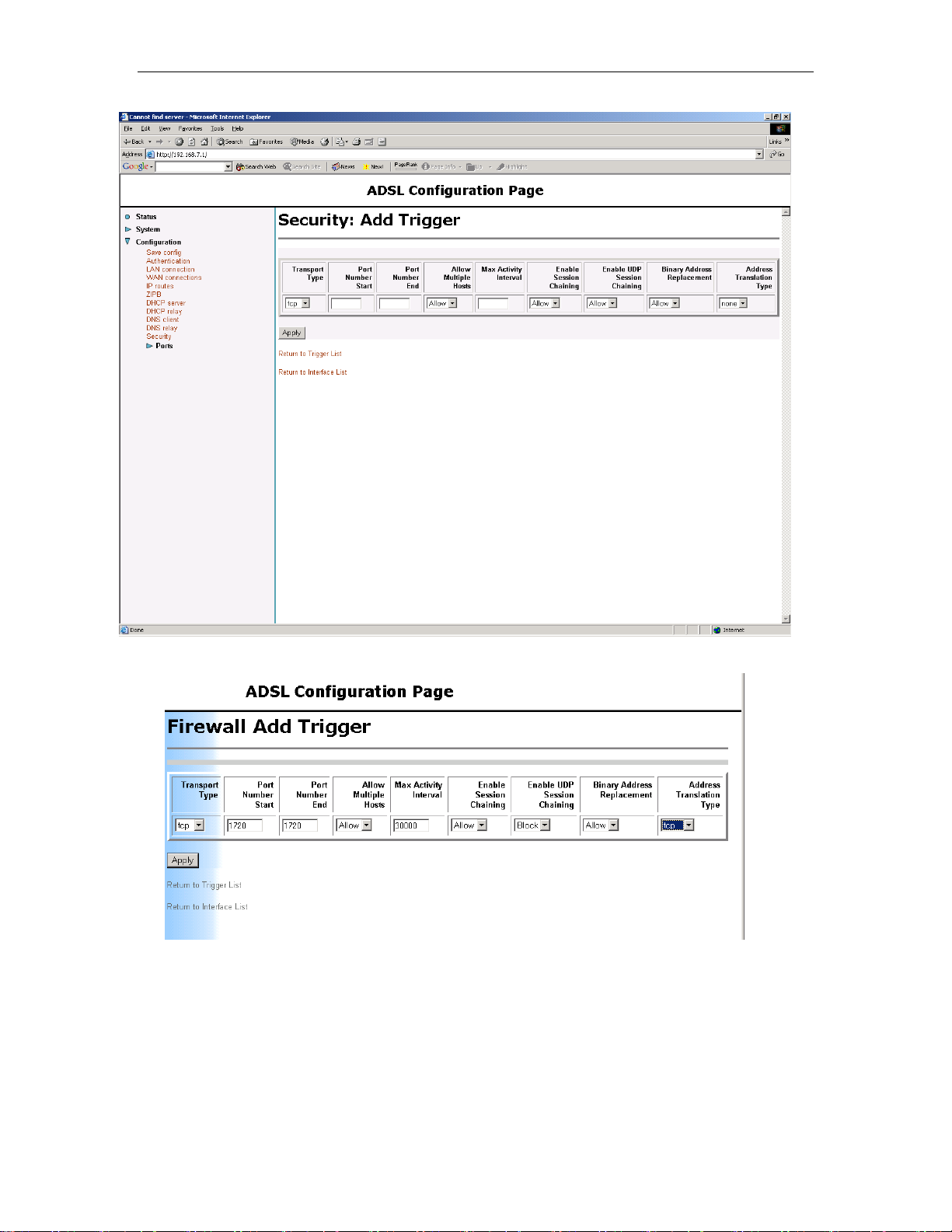
This trigger will enable you to do outgoing Netmeeting and H.323
calls. If you want to accept incoming H.323 calls then you need to
set-up a port forwarding rule on port 1720/TCP to point to your
computer (see below for details about how to set reserved port
rules).
Remember to do ‘System/Save’ to store the settings.
5.5 Configuring the ‘Security Interface’ to allow ftp
Some ftp applications seem to need a security trigger to allow data
flow. The figure below shows the settings required:
58
Page 59

Solwise SSR725 SDSL Ethernet Router User’s Guide Chapter 5. How to…
5.6 Firewall Features
The 7x5 includes a full featured firewall, with capabilities such as
intrusion detection, packet filtering and NAT. There are many
different ways for configuring a firewall but this section gives an
overview of the options.
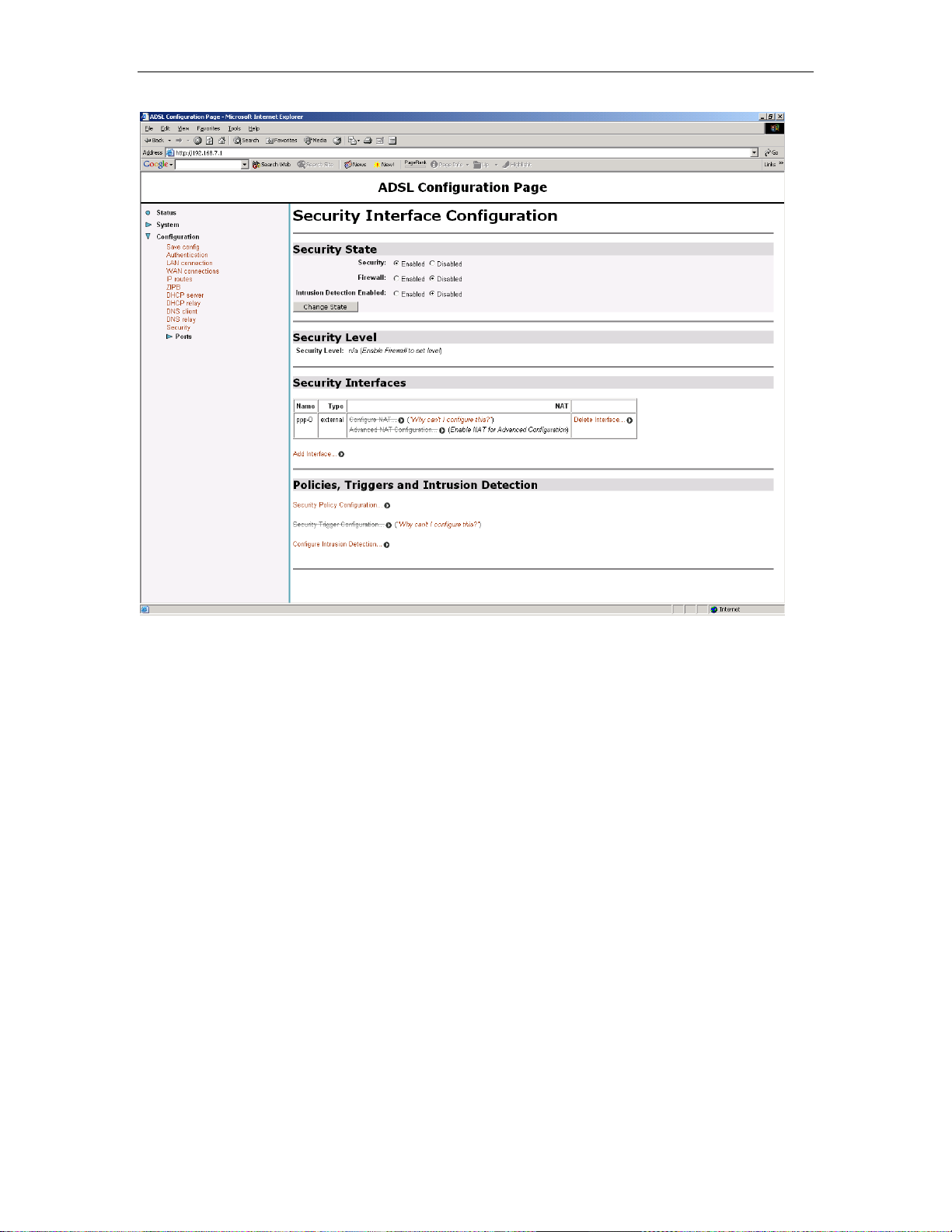
5.6.1 Intrusion Detection
Intrusion detection protects you from certain types of
common attacks and will block access from hosts
attempting these attacks.
To configure intrusion detection you must first click on
the Security (NAT,Firewall) link on the left hand side
under Configuration.
Make sure that Intrusion Detection is ticked as enabled.
Click Change State to change the state.
At the bottom of the screen is the Policies,
Triggers and Intrusion Detection section.
Click on Configure Intrusion Detection to
configure the options for Intrusion detection.
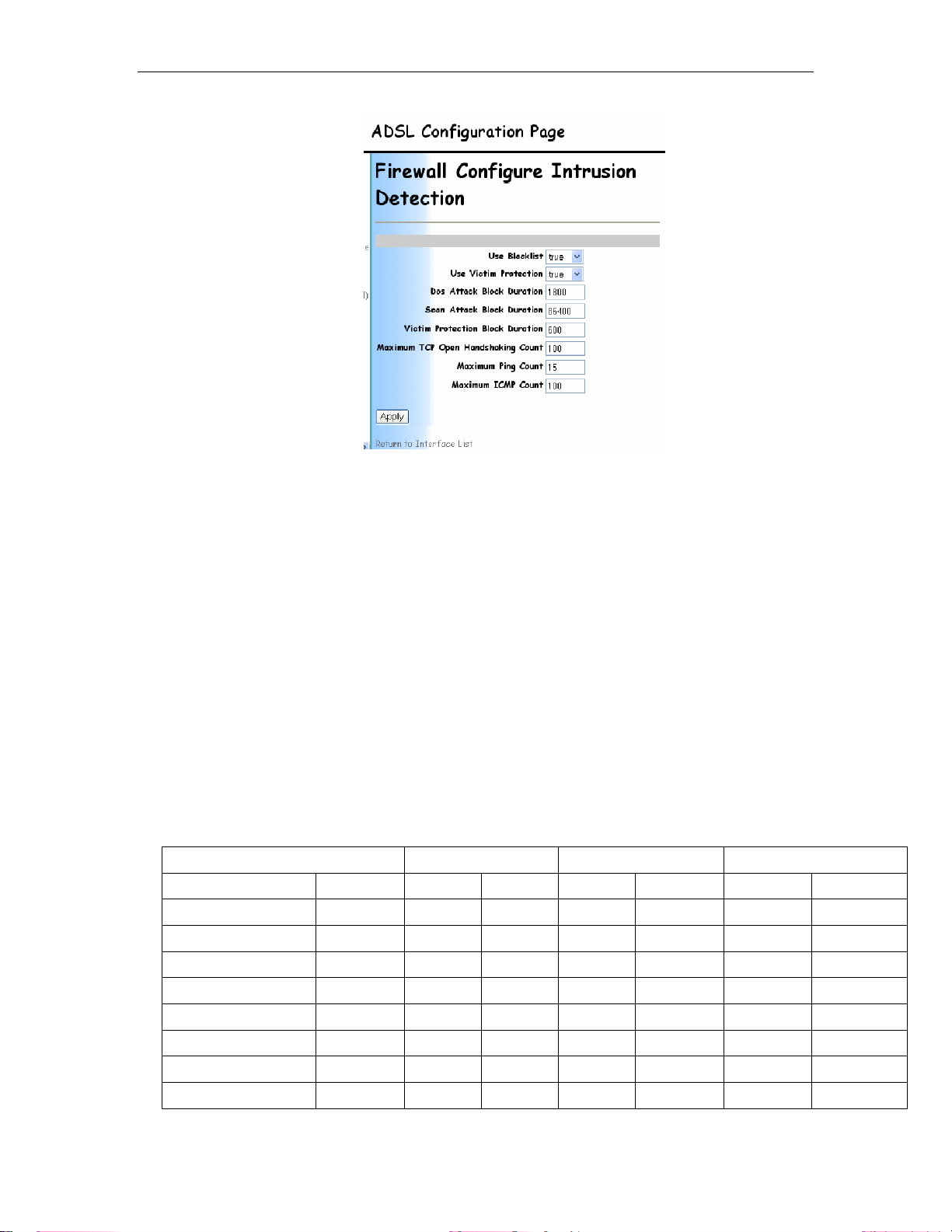
The following screen then shows the options that can be configured
for intrusion detection. All values should be left at defaults unless
you specifically want to change any of the settings as per your own
security policy.
59
Page 60
Chapter 5. How to… Solwise SSR725 SDSL Ethernet Router User’s Guide
The only exception is the top two options Use Blacklist and Use
Victim Protection these should both be enabled so Intrusion
detection will be fully functional.
Click Apply to keep the changes.
If you are unsure about any settings or values then you are advised
to leave the values set to default.
When you have finished altering the settings then remember to
save the new configuration and restart.
5.6.2 Packet Filtering
Packet filtering allows you to block certain types of traffic, such as
telnet access or FTP applications, the 7x5 allows you to completely
customise what you want to filter. There are pre set security levels
of none, low, medium & high. The tables below The following
tables describe the default policies enabled in the firewall for each
of the high, medium and low security levels. The tables tell you
whether a certain service can be received in or allowed out by a
specific policy:
HIGH SECURITY LEVEL External < > Internal External < > DMZ DMZ < > Internal
Service Port In Out In Out In Out
http 80
dns 53
ftp 21
telnet 23
smtp 25
pop3 110
nntp 119
real audio/video 7070
x
x
x x x
x x x x x x
x
x
x x x x x x
x x x x x x
3 3 3 3 3
3
3 3 3 3 3
3 3 3 3 3
x
3
3
x
x
3
3
60
Page 61

Solwise SSR725 SDSL Ethernet Router User’s Guide Chapter 5. How to…
icmp N/A
H.323 1720
T.120 1503
SSH 22
MEDIUM SECURITY LEVEL External < > Internal External < > DMZ DMZ < > Internal
Service Port In Out In Out In Out
http 80
dns 53
ftp 21
telnet 23
smtp 25
pop3 110
nntp 119
real audio/video 7070
icmp N/A
H.323 1720
T.120 1503
SSH 22
LOW SECURITY LEVEL External < > Internal External < > DMZ DMZ < > Internal
Service Port In Out In Out In Out
http 80
dns 53
ftp 21
telnet 23
smtp 25
pop3 110
nntp 119
real audio/video 7070
icmp N/A
H.323 720
T.120 1503
SSH 22
x
x x x x x x
x x x x x x
x x x x x x
x
x
x
x
x
x
x
3
x
x
x
x
x
3 3 3 3 3 3
x
x
x
x
x
3
3 3 3 3 3 3
3 3 3 3 3 3
3 3 3 3 3 3
3 3 3 3 3 3
3
3 3 3 3 3
3 3 3 3 3
3 3 3 3 3
3
3 3 3 3 3
3 3 3 3 3
3 3 3 3 3
x x
3
3
3
3
3 3 3 3 3
3 3 3 3 3
3 3 3 3 3
3 3 3 3 3
3 3 3 3 3
3 3 3 3 3
x
x
3
x
3
x
x
x
x
x
3 3 3 3
3
3
3
3
3
3
x
X
X
X
X
X
3
3
3
3
3
3
These presets block and allow common applications. They will suit
most needs, if you have a specific application you may want to add
your own filters to either allow or deny traffic.
To configure packet filtering you must first click on the Security link
on the left hand side under Configuration.
61
Page 62

Chapter 5. How to… Solwise SSR725 SDSL Ethernet Router User’s Guide
Make sure that Firewall is ticked as enabled.
Click Change State to change the state.
To modify what types of traffic you want to
filter, click on the Security Policy
Configuration link under the
Policies, Triggers and Intrusion Detection
section at the bottom of the screen.
62
Next click on New Policy…
The Security Add Policy screen will appear. Select interfaces of
type external to internal.
Page 63

Solwise SSR725 SDSL Ethernet Router User’s Guide Chapter 5. How to…
Next decide on whether you want validators to block or allow traffic.
Selecting “allow” will allow
validators but block
Selecting “block” will block
traffic from all hosts which have
traffic from other all other hosts.
traffic from all hosts which have
validators but allow traffic from all other hosts.
For example, let’s say that you DON’T want client 192.168.7.5 on
your network to be able to do any web access (not sure why you’d
want to do this but it will serve as an example).
So this will be a “block” policy
Then click on Apply….
Now you need to do two things: Set up a port filter on port 80 (as
used for web access) and next setup your host as 192.168.7.5 for
this policy.
63
Page 64

Chapter 5. How to… Solwise SSR725 SDSL Ethernet Router User’s Guide
So, first, to create a port filter… Click on Port Filters….
Now decide if you need a filter on TCP, UDP or a filter to act upon
any IP packet (Raw IP).
For our example of blocking web access for our host on
192.168.7.5 you need to add a TCP filter. So, click on ‘Add TCP
Filter’…
Now enter port number 80 for the start and end values, then select
‘Block’ for both inbound and outbound traffic. Finally click on Apply.
64
Page 65

Solwise SSR725 SDSL Ethernet Router User’s Guide Chapter 5. How to…
Now go back to the Policy List (click on link) and, from the Firewall
Policy Configuration, click on Host Validators under Policy
Configuration.
Now click on ‘Add Host Validator’
65
Page 66

Chapter 5. How to… Solwise SSR725 SDSL Ethernet Router User’s Guide
Now enter the IP address and subnet for the host and then click on
Apply…
You should now save the configuration and reset the router.
66
Page 67

Solwise SSR725 SDSL Ethernet Router User’s Guide Chapter 5. How to…
5.7 Using your 7x5 Router with fixed IP address
Most users will use their router with NAT enabled. This allows them
to ‘share’ their internet connectivity across
their whole network without needing a
block of static IP addresses from the ISP
i.e. the ISP sees the whole of your LAN as
a single IP address and the router
automatically sorts out traffic to the correct
local clients:
However using NAT has it’s advantages
and disadvantages. The advantages are it
allows you to easily run multiple PC’s
through a single user ISP account and it
acts as a natural firewall stopping
unsolicited incoming traffic. However the
disadvantage of NAT is that some software
needs the IP address of
the PC to be ‘exposed’
to the outside world –
this is just what NAT
stops! For some
applications you can get
around this using port
forwarding but not
always. In this case the
only way around the
problem is to turn NAT
off and open up you
network. To do this you
will first of all need to get
a block of IP addresses
from your ISP so that
you can allocate an IP
address to each of your
clients.
First of all setup a ‘normal’ NAT configuration (as detailed above)
and check that you can successfully connect to the internet through
the router.
Then, from the Status page click on the ppp-0 link in the WAN
Status box…
67
Page 68
Chapter 5. How to… Solwise SSR725 SDSL Ethernet Router User’s Guide
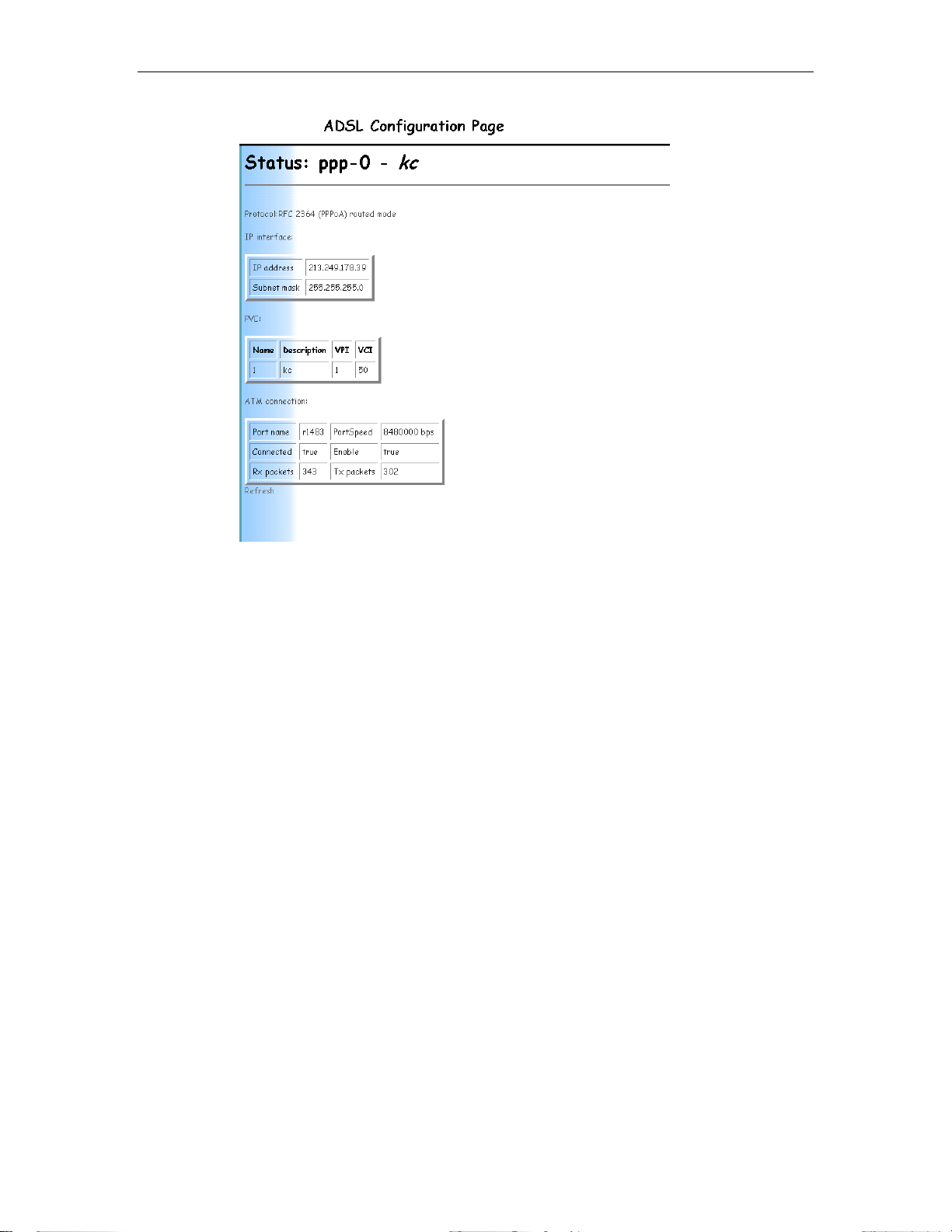
Now, note down the IP interface IP address; you’ll need this in the
non-NAT setup detailed below. E.g. 213.249.178.39.
Next you need to turn NAT off. Goto Advanced
Configuration/Security…
68
Page 69

Solwise SSR725 SDSL Ethernet Router User’s Guide Chapter 5. How to…
Now click on ‘Disable NAT to internal interfaces’….
Now there is no NAT routing between the WAN (internet) and LAN
(your PC’s) sides of the router.
The next step is to assign the correct IP address to the LAN side of
the router (the IP address for the WAN side of the router should be
automatically assigned to the router when it logs into the ISP - see
above).
Click on “Configuration/LAN connection”:
69
Page 70

Chapter 5. How to… Solwise SSR725 SDSL Ethernet Router User’s Guide
Now, enter in the Primary IP Address settings the WAN IP address
and also the subnet mask. Use the subnet mask as advised by your
ISP e.g. if you have a block of 8 fixed IP’s then the subnet mask is
probably 255.255.255.248. Now click on Apply.
Please note that, once you change the LAN address you will then
have to immediately change the IP address of your PC so you can
‘see’ the router again. So you should now change the IP address’s
and subnet masks of your clients with the rest of the IP addresses
you received from your ISP.
With your PC setup with the new address you should now be able
to login in the web configuration again (using the new LAN address
for the router).
To complete the multiple IP setup you now need to connect using
console CLI mode. You can do this using the serial port console or
via telnet (details of console connection are given above).
From the console prompt issue the following commands:
pppoa set transport ppp-0 subnetmask 255.255.255.255
pppoa set transport ppp-0 localip <WAN IP address>
But substitute your WAN IP address (as you have now assigned to
the router LAN address).
70
Finally issue the CLI commands to save the configuration:
Page 71

Solwise SSR725 SDSL Ethernet Router User’s Guide Chapter 5. How to…
Now restart the router (System/Save Config/Restart).
Please note, with NAT not running both the LAN side and WAN side
of the router are visible from the ISP (internet) along with your whole
network i.e. you will have no security! You are advised to configure
the built-in firewall to protect your LAN.
5.8 Enabling DHCP Server Mode
The 7x5 has an inbuilt DHCP server which you can use to assign IP
addresses and TCP setup to your client computers. To enable
DHCP server goto “Configuration /DHCP server”
71
Page 72

Chapter 5. How to… Solwise SSR725 SDSL Ethernet Router User’s Guide
To enable DHCP server you first of all need to goto Advanced
Options and setup the Subnet parameters…
72
Page 73

Solwise SSR725 SDSL Ethernet Router User’s Guide Chapter 5. How to…
Things you should setup are:
Specify a start and end address values for the IP allocation range.
Specify the DNS value you want to send to the clients (or tick the
box to use the router as DNS relay).
Tick the box to use the router as the default gateway.
e.g.
73
Page 74

Chapter 5. How to… Solwise SSR725 SDSL Ethernet Router User’s Guide
Then click on OK…
Now click on Enable from the DHCP setup screen…
74
Page 75

Solwise SSR725 SDSL Ethernet Router User’s Guide Chapter 5. How to…
The Advanced Options can also be used to change lease times and
control functions like allowing unknown clients, these should be left
at defaults unless you have specific reasons for changing them.
When you’ve finished the configuration you must save the settings
and do a router restart.
5.9 Altering the configuration user name and password
Goto Configuration/Authentication…
75
Page 76

Chapter 5. How to… Solwise SSR725 SDSL Ethernet Router User’s Guide
First of all click on Create a new user…
On the next screen enter the new user details…
76
Remember to change the May login? to true to enable the new user
to login!
Then click on Create to set the new user…
Page 77

Solwise SSR725 SDSL Ethernet Router User’s Guide Chapter 5. How to…
Now save the settings again (System/Save config).
Now you should test the new user so Restart (System/Restart) and
shut your browser down…. Then allow the router about 30 seconds
to reboot before starting your browser up and going to the router
set-up screen again. Then try to enter and configuration screen.
You should be prompted to enter a username and password; try the
new one you’ve created. It should work. Only when you’ve proved
the new user and password it works should you then go and delete
the old admin user (System/Authentication/Edit user and then click
on Delete this user).
Yet again you should now save the new settings so System/Save
config…
77
Page 78

Chapter 6. Firmware Upgrade Solwise SSR725 SDSL Ethernet Router User’s Guide
6 Firmware Upgrade
6.1 Upgrading to a new firmware version using http
Please note that the correct file format for web based firmware
upgrade should be ‘.tar’. If the upgrade file you have is ‘.bin’ format
then this is NOT the correct format to upgrade using the web
interface. Upgrade using ‘.bin’ files can only be done using xmodem
or a bootp/tftp server utility. Assuming you have the correct firmware
file, from the web browser configuration screen go to the
System/Upgrade menu option:
78
Click on Browse to select the firmware file (please note of the file
was supplied zipped then you must first unzip the file before use).
Page 79

Solwise SSR725 SDSL Ethernet Router User’s Guide Chapter 6. Firmware Upgrade
Then Click on Upgrade and wait. Firmware upgrade should only
take a few minutes. During this period do not touch the router or
browser – leave them alone until the upgrade file is loaded.
79
Page 80

Chapter 6. Firmware Upgrade Solwise SSR725 SDSL Ethernet Router User’s Guide
After the flash update is complete the following screen should
display.
6.1.1 When things go wrong!
80
You should now restart.
If something goes wrong with the firmware upload which causes
only part of the firmware to install then you will need to connect to
the console port of the router via the serial port of your computer
using terminal software (e.g. Windows Hyperterminal); use serial
port settings of 9600bps, 8 data, 1 stop, no parity, none flow control
(details are given above on how to enter console mode).
If the prompt on the console screen is either ‘]’ or the word ‘DEBUG’
or ‘DSL>’ or the MAC address of the router then the firmware’s
corrupted. In which case you will have to manually reload the
firmware files. Here is the basic method for doing a manual full
firmware upload.
First of all hold down the space bar whilst rebooting the router (i.e.
power off/on). The router should reboot to the ‘]’ prompt. Now enter
the command ‘xmodem’ and then, from the Transfer/Send File
menu (assuming you are using Hyperterminal), browse and select
the bootcode.bin file from the firmware. Click on send and wait
Page 81

Solwise SSR725 SDSL Ethernet Router User’s Guide Chapter 6. Firmware Upgrade
whilst the bootcode bin file is loaded (takes about 10 minutes).
When it’s finished enter ‘quit’ and the router should then show the
mac address prompt. Now enter the command ‘flashfs rewrite
boot.bin’ to save the bootcode file followed by ‘flashfs update.
Now hold down the space bar and reboot a second time to the ‘]’
prompt. Now use xmodem to load the second, main firmware file.
Enter ‘quit’ when it’s finished and it should then show the ‘login’
prompt. Now enter ‘admin’ to login and the password ‘admin’.
At the ‘’ prompt enter the command ‘console enable’ and then the
‘DSL>’ prompt should show. Now enter the command ‘flashfs
update’ to save the firmware file to flash.
The firmware should now be fully loaded.
6.2 Using xmodem to upload the firmware files
You can use the xmodem technique to upload either the bootcode
or the main firmware files using a serial cable and terminal software
(for example Windows Hyperterminal). Please note you will need
firmware files which have the .bin extension. The .tar extension file
cannot be used; this file type is for http upgrade only (see above).
6.2.1 Loading a new bootcode bin firmware file
First of all you need to connect using a console (serial) programme
to the router. Details are given in the set-up guide but in simple
terms it’s 9600 bps, 8 data, 1 stop, no parity, no flowcontrol. Please
note these instructions assume you are using Windows
Hyperterminal. If you are using another console programme then
the same method applies though the actual terminal commands
and screen may differ slightly.
Now switch your router on whilst holding down the space-bar. This
is the sort of screen you should see.
81
Page 82

Chapter 6. Firmware Upgrade Solwise SSR725 SDSL Ethernet Router User’s Guide
The router should now boot to the ‘]’ prompt. It’s now ready to
accept the firmware file.
Type “xmodem fast”
82
The router has now changed it’s port speed to 38400 bps so you
now need to change your terminal set-up. To do this on
Hyperterminal select Call/Disconnect…
Page 83

Solwise SSR725 SDSL Ethernet Router User’s Guide Chapter 6. Firmware Upgrade
Then File/Properties
The click on Configure…
83
Page 84

Chapter 6. Firmware Upgrade Solwise SSR725 SDSL Ethernet Router User’s Guide
Change the port speed to 38400 and then click on OK.
Then select Call/Call…
Now you are ready to start sending the bootcode file.
84
Select Transfer/Send file…
Page 85

Solwise SSR725 SDSL Ethernet Router User’s Guide Chapter 6. Firmware Upgrade
Click on browse so you can select the bootcode bin file (called
boot.bin in this example).
Now you are ready to send the file..
85
Page 86
Chapter 6. Firmware Upgrade Solwise SSR725 SDSL Ethernet Router User’s Guide
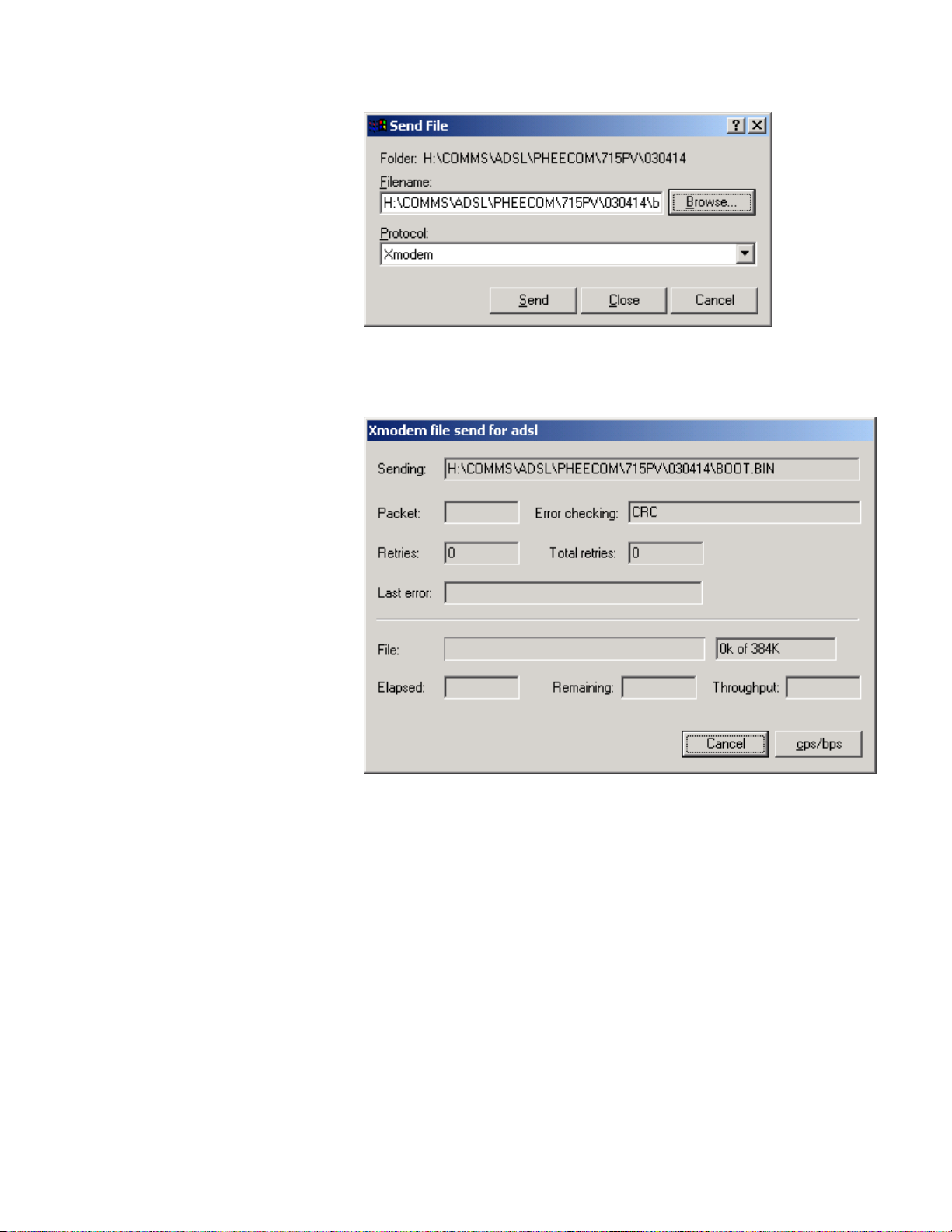
Click on Send…
86
The file should now start to send…. Notice the Packet count goes
up and the indicator bar starts to increase…
Page 87

Solwise SSR725 SDSL Ethernet Router User’s Guide Chapter 6. Firmware Upgrade
When the file send is finished then a screen similar to the following
is shown…
You should now type quit..
87
Page 88

Chapter 6. Firmware Upgrade Solwise SSR725 SDSL Ethernet Router User’s Guide
Now the port speed of the router has changed back to the normal
setting of 9600 so you need to change the set-up of your terminal
back to 9600…
You should now see the MAC address prompt (press enter maybe
to bring the mac address prompt).
Now you need to enter the command “flashfs rewrite boot.bin”…
88
Page 89

Solwise SSR725 SDSL Ethernet Router User’s Guide Chapter 6. Firmware Upgrade
Now…. if you are now intending to load the main firmware bin
file (as detailed below) you should do the command
Flashfs update
This will update the flash filing system ready for the main bin file.
Don’t use the update command unless you are prepared to
immediately load the main firmware file.
You can now reboot your router (power off/on)…
89
Page 90

Chapter 6. Firmware Upgrade Solwise SSR725 SDSL Ethernet Router User’s Guide
Done…!
6.2.2 Loading a new main bin firmware file
As when loading a bootcode bin file, you first of all you need to
connect using a console (serial) programme to the router. Details
are given in the set-up guide but in simple terms it’s 9600 bps, 8
data, 1 stop, no parity, no flowcontrol. Please note these
instructions assume you are using Windows Hyperterminal. If you
are using another console programme then the same method
applies though the actual terminal commands and screen may differ
slightly.
Now switch your router on whilst holding the space-bar down. This
is the sort of screen you should see.
90
Page 91

Solwise SSR725 SDSL Ethernet Router User’s Guide Chapter 6. Firmware Upgrade
The router should now boot to the ‘]’ prompt. It’s now ready to
accept the firmware file.
Type “xmodem fast”
The router has now changed it’s port speed to 38400 bps so you
now need to change your terminal set-up. To do this on
Hyperterminal select Call/Disconnect…
91
Page 92

Chapter 6. Firmware Upgrade Solwise SSR725 SDSL Ethernet Router User’s Guide
Then File/Properties
92
The click on Configure…
Page 93

Solwise SSR725 SDSL Ethernet Router User’s Guide Chapter 6. Firmware Upgrade
Change the port speed to 38400 and then click on OK.
Then select Call/Call…
Now you are ready to start sending the bootcode file.
Select Transfer/Send file…
93
Page 94

Chapter 6. Firmware Upgrade Solwise SSR725 SDSL Ethernet Router User’s Guide
Click on browse so you can select the bootcode bin file (called
flash.bin in this example).
94
Now you are ready to send the file..
Page 95

Solwise SSR725 SDSL Ethernet Router User’s Guide Chapter 6. Firmware Upgrade
Click on Send…
The file should now start to send…. Notice the Packet count goes
up and the indicator bar starts to increase…
When the file send is finished then a screen similar to the following
is shown…
You should now type quit..
95
Page 96

Chapter 6. Firmware Upgrade Solwise SSR725 SDSL Ethernet Router User’s Guide
Now the port speed of the router has changed back to the normal
setting of 9600 so you need to change the set-up of your terminal
back to 9600…
You should now see the Login prompt (press enter maybe to bring
the prompt up).
96
Page 97

Solwise SSR725 SDSL Ethernet Router User’s Guide Chapter 6. Firmware Upgrade
Login using the username and password (normally ‘admin’ and
‘admin’).
Now you need to enter the command “console enable”…
97
Page 98

Chapter 6. Firmware Upgrade Solwise SSR725 SDSL Ethernet Router User’s Guide
You should now see the IP address prompt.
Enter the command “flashfs update” to write the new firmware to
flash…
98
Page 99

Solwise SSR725 SDSL Ethernet Router User’s Guide Chapter 6. Firmware Upgrade
When it’s done you are now ready to reboot (power off/on)…
99
Page 100

Chapter 7. Appendix A Product Specifications Solwise SSR725 SDSL Ethernet Router User’s Guide
7 Appendix A Product Specifications
Data Connection
Supports data rates from 192Kbps to 2.3Mbps (G.SHDSL) on downstream and upstream with 8Kbps
granularity
• Connect distance: over 16kfeet at 1.5Mbps on 26AWG wire
Communication
Standards Compliant
DSL:
• ANSI T1E1.4 (HDSL2)
• ITU-T G.991.2 (G.SHDSL)
• ITU-T G.994.1 (G.hs)
• Single-pair 2B1Q SDSL
• Configurable for CO and CPE
• Proprietary Over-over- POTS to works with ADSL splitters and micro-filters
Encapsulation protocols:
• RFC 1483/2684 (Multiple Protocol over ATM PVC, Bridged & Routed PDU for LLC/SNAP & VC Mux
encapsulation)
• RFC 1577(Classic IP over ATM)
• RFC 2364(PPP over ATM, LLC/SNAP & VC Mux encapsulation)
• RFC 2516 (PPP over Ethernet)
ATM:
• ATM Forum UNI 3.0, 3.1 and 4.0 signaling
• ATM Forum ILMI 4.0
• ATM Forum LANE 1.0 client, MTU=1516,over SVC only
• ATM supports AAL5, AAL3/4, AAL2 and AAL0
• ATM Traffic shaping supports CBR and UBR, VBR-rt AND VBT-nrt
• OAM F4 and F5 segment end-to-end loopback (F4 on all VPIs, F5 on VPI 0 only)
Bridging:
Bridge features conformance to IEEE 802.1d and supports spanning tree algorithm and protocol.
Routing:
• RIP version 1(RFC 1058) and version 2(RFC 1723)
• ARP (RFC 1293, supports only one single subnet)
Management and Monitoring:
• DHCP (RFC 2131, RFC 2132) server, relay and client
• DNS Relay and client
• BOOTP (RFC 2131, RFC 2132)
• TFTP revision 2(RFC 1350)
• SNMP version 1(RFC 1155, RFC 1157, RFC 1213)
• TELNET server (RFC 854, 855, 857, 858)
• Command line configuration thru serial console port or TELNET session
• Password protection from access configuration manager
• Web-based Configuration
NAT:
NAT (NAPT, IP Masquerading)
VPN:
PPTP VPN tunneling
PPP:
PAP (RFC 1334) and CHAP authentication protocol
Supported OS
Windows 95, 98, ME, 2000, NT4.0, XP, Mac, UNIX & Linux
EMC Emission
FCC part 15 & 68, CE CTR21
100
 Loading...