


Solwise Ltd.
Set-up instructions for
Solwise SAR715PV
ADSL Router with
Hardware VPN
www.solwiseforum.co.uk
The Solwise Forum is designed to be the first port-of-call for technical support and sales advice for the whole
Solwise product range.
Please check the forum for coverage on any technical problems you have. Many people have trodden your
path before you, and a quick check on the forum will reduce the pressure on our support staff.
May 9 2003

Chapter 1. Introduction Solwise SAR715PV ADSL Ethernet Router User’s Guide
Notification is hereby given that Solwise Ltd. reserves the right to modify, change, update or
revise this document from time to time as required without the prior obligation to notify any
person, company or organization. Further, Solwise makes no warranty or representation, either
express or implied, with respect to merchantability, or fitness of its products for a particular
purpose.
Solwise Ltd.
13/15 Springfield Way
Anlaby
Hull HU10 6RJ
UK
Tel 0845 458 4558 (local rate)
Fax 0845 458 4559
Email sales@solwise.co.uk
Http www.solwise.co.uk
Copyright
All rights reserved. No part of this document may be reproduced in any form or by any means
without written permission from the product manufacturer.
Changes are periodically made to the information in this document. They will be incorporated in
subsequent editions. The product manufacturer may take improvement and/or changes in the
product described in this document at any time.
FCC compliance
This equipment complies with Part 68 of the FCC Rules. On this equipment is a label that contains,
among other information, the FCC registration number and Ringer Equivalence Number (REN) for this
equipment. You must, upon request, provide this information to your telephone company.
If your telephone equipment causes harm to the telephone network, the Telephone Company may
discontinue your service temporarily. If possible, they will notify in advance. But, if advance notice isn’t
practical, you will be notified as soon as possible. You will be informed of your right to file a complaint
with the FCC.
Your telephone company may make changes in its facilities, equipment, operations, or procedures
that could affect proper operation of your equipment. If they do, you will be notified in advance to give
you an opportunity to maintain uninterrupted telephone service. The FCC prohibits this equipment to
be connected to party lines or coin-telephone service.
In the event that this equipment should fail to operate properly, disconnect the equipment from the
phone line to determine if it is causing the problem. If the problem is with the equipment, discontinue
use and contact your dealer or vendor.
DOC compliance information
NOTICE: The Canadian Department of Communications label identifies certified equipment. This
certification means that the equipment meets certain telecommunications network protective,
2

SAR715PV User’s Guide
operational and safety requirements. The Department does not guarantee the equipment will operate
to the user’s satisfaction.
Before installing this equipment, users ensure that it is permissible to be connected to the facilities of
the local Telecommunications Company. The equipment must also be installed using an acceptable
method of connection. The customer should be aware that compliance with the above conditions
might not prevent degradation of service in some situations.
Repairs to certified equipment should be made by an authorized Canadian maintenance facility
designated by the supplier. Any repairs or alterations made by the user to this equipment, or
equipment malfunctions, may give the telecommunications company cause to request the user to
disconnect the equipment.
Users should ensure for their own protection that the electrical ground connections of the power utility,
telephone lines and internal metallic water pipe system, if present, are connected together. This
precaution may be particularly important in rural areas.
CAUTION: Users should not attempt to make such connections themselves, but should contact the
appropriate electric inspection authority, or electrician, as appropriate.
NOTICE: The Load Number (LN) assigned to each terminal device denotes the percentage of the
total load to be connected to a telephone loop which is used by the device, to prevent overloading.
The termination on a loop may consist of any combination of devices subject only to the requirement
that the sum of the Load Numbers of all the devices does not exceed 100.
European CTR 21 compliance
The equipment has been approved in accordance with Council Decision 98/482/EC for pan-European
single terminal connection to the public switched telephone network (PSTN). However, due to
differences between the individual PSTNs provided in different countries, the approval does not, of
itself, give an unconditional assurance of successful operation on every PSTN network termination
point. In the event of problem, you should contact your equipment supplier in the first instance.
3


Solwise SAR715PV ADSL Ethernet Router User’s Guide Chapter 1. Introduction
Table of Contents
1 Introduction..........................................................9
1.1 Features......................................................................9
1.2 What’s in the package?............................................10
1.3 Front Panel ...............................................................11
1.4 Rear Panel................................................................12
2 Connecting to your network and line.................13
3 Setting up TCP/IP on your computer ................15
3.1 Installing TCP protocol on your PC..........................15
3.2 Configuring TCP/IP Protocol for your PC................17
3.3 Setting up TCP/IP protocol on your Mac.................19
4 Quick Router configuration using your
browser...........................................................22
4.1 What you see on the Start-up page.........................23
4.1.1 About the Status Page....................................25
4.2 Setting up a basic NAT router configuration............27
4.2.1 Clearing to factory defaults .............................27
4.2.2 Creating a PPPoA WAN connection
for the UK..................................................................30
4.2.3 Creating a PPPoE WAN connection
for Ireland & France..................................................40
4.2.4 Disabling DHCP Server ..................................42
4.2.5 Saving the configuration and restarting..........44
4.2.6 Testing the connection....................................45
5 The Configuration Screens in More Detail........47
5.1 About the System menu...........................................47
5.1.1 Error Log..........................................................47
5.1.2 Remote Access...............................................47
5.1.3 Upgrade...........................................................48
5.1.4 Restart .............................................................49
5.2 Configuration ............................................................50
5.2.1 Save configuration ..........................................50
5.2.2 Authentication..................................................51
5.2.3 LAN Connections............................................52
5.2.4 WAN Connections...........................................53
5.2.5 IP Routes.........................................................54
5

Chapter 1. Introduction Solwise SAR715PV ADSL Ethernet Router User’s Guide
5.2.6 DHCP Server ..................................................56
5.2.7 DNS Client.......................................................58
5.2.8 DNS Relay.......................................................59
5.2.9 Security............................................................60
5.2.10 IPSec.............................................................74
5.2.11 PPTP .............................................................74
5.2.12 L2TP..............................................................74
5.2.13 Ports ..............................................................74
6 VPN Configuration ............................................78
6.1 Enabling the Firewall ................................................78
6.2 IPSec VPN Configuration.........................................80
6.2.1 Pre-Shared Key...............................................80
6.2.2 Digital Signature VPN Configuration ..............84
6.3 PPTP Access Concentrator (PAC) and
L2TP Access Concentrator (LAC) Configuration ...........89
6.4 Configuring PPTP or L2TP Client-Initiated
Tunneling with VPN Concentrator ..................................91
6.4.1 Create two dial-up networking (DUN)
connections...............................................................91
6.4.2 Disabling IPSec on the Windows 2000
PC 92
6.5 Basic Terms and Concepts......................................92
7 How to…............................................................96
7.1 How to enter Command Line Interface mode .........96
7.1.1 Telnet...............................................................96
7.1.2 Using terminal program via serial
console port ..............................................................96
7.1.3 Basic CLI syntax .............................................99
7.2 Altering the LAN IP address of the router..............101
7.3 Using your 715PV Router with fixed IP
address ..........................................................................102
7.4 Set-up port forwarding............................................106
7.5 Configuring the ‘Security Interface’ to allow
Netmeeting ....................................................................109
7.6 Configuring the ‘Security Interface’ to allow
ftp 111
7.7 Configuring the ‘Security Interface’ for MS
Messenger to work........................................................112
7.8 Firewall Features....................................................112
6
7.8.1 Intrusion Detection ........................................112

Solwise SAR715PV ADSL Ethernet Router User’s Guide Chapter 1. Introduction
7.8.2 Packet Filtering..............................................113
7.9 Enabling DHCP Server Mode ................................119
7.10 Altering the configuration user name and
password .......................................................................120
8 Firmware Upgrade ..........................................122
8.1 Upgrading from to a new 8.2 firmware
version using http ..........................................................122
8.1.1 When things go wrong! .................................122
8.2 Using xmodem to upload the firmware files ..........123
8.2.1 Loading a new bootcode bin firmware
file 123
8.2.2 Loading a new main bin firmware file...........131
9 DNS Addresses...............................................141
10 About Universal Plug’n Play and the
SAR715PV Router .......................................143
10.1 UPNP IN GENERAL.............................................143
10.1.1 Overview .....................................................143
10.1.2 Background .................................................143
10.2 THE INTERNET GATEWAY DEVICE.................145
10.2.1 The IGD concept.........................................145
10.2.2 Network Address Translation (NAT) ..........145
10.2.3 NAT Traversal.............................................146
10.3 UPNP SUPPORT IN OPERATING
SYSTEMS .....................................................................146
10.3.1 Microsoft Windows......................................146
10.3.2 Macintosh OS..............................................146
10.3.3 Linux ............................................................146
10.4 UPNP SUPPORT In The 715PV Routers............147
10.4.1 Windows ME ...............................................147
10.4.2 Windows XP................................................149
11 Appendix A Product Specifications.................161
11.1 Software features..................................................163
12 Appendix B Troubleshooting...........................166
12.1 Diagnostics with the LEDs....................................166
12.2 Problems when configure the Modem via
the console port .............................................................166
12.3 Problems when connecting to the Modem
via Ethernet....................................................................166
7

Chapter 1. Introduction Solwise SAR715PV ADSL Ethernet Router User’s Guide
12.4 Problems when accessing the Internet or
remote network..............................................................167
12.5 Diagnosing Problem using IP Utilities ..................168
12.5.1 ping..............................................................168
12.5.2 nslookup ......................................................169
12.6 MTU value. What is it and why does having
the correct value matter? ..............................................169
12.6.1 What are the symptoms of having a
wrong MTU value? .................................................169
12.6.2 So what is it?...............................................170
12.6.3 Why is it important? ....................................170
12.6.4 So how do I set the MTU value on
my Windows PC?...................................................171
13 Appendix C Government compliance
notices ..........................................................173
14 Appendix D IP Addresses, Network
Masks, and Subnets.....................................175
14.1 IP Addresses.........................................................175
14.1.1 Structure of an IP address..........................175
14.1.2 Network classes..........................................176
14.2 Subnet masks .......................................................176
15 Appendix E Binary Numbers...........................179
15.1 Binary Numbers ....................................................179
15.1.1 Bits and bytes..............................................179
16 Appendix F Useful Links .................................181
17 Appendix G Glossary ......................................182
8

1 Introduction
The SAR715PV is powerful, high integration function Router which
provides secure communication between networks and users with a
DSL connection to Internet. For the ADSL line, it gives excellent
performance and compliance with ITU-T G.dmt (G.992.1), ITU-T
G.lite (G.992.2) and ANSI T1.413 issue standards. For VPN
functions, it provides full IPSec, PPTP, LT2P VPN termination
functions. The Firewall function supports Denial of Service
prevention and Trojan Horse prevention which meets the ICSA
firewall standard. The general function of SAR715PV is defined as a
“ADSL Modem Router” with connectivity as shown below. In this
mode, you may connect the “LINE” port to an ADSL-ready
telephone line. The ADSL/WAN LED will indicate connection.
Connect the LAN port to a Network device.
1.1 Features
• Compliant with ITU-T G.dmt (G.992.1) , ITU-T G.lite
(G.992.2), G.994,1 (G.hs) standards
• VPN function supports RFC 2401, RFC 2411, RFC 2402,
RFC 2406, RFC 2393, RFC 2407, RFC 2104, RFC 2403,
RFC 2404, all AH and ESP Transforms function, and LZS
Transform for IPCOMP.
• Built in VPN Server ability for IPSEC (with Pre-Shared Key
and Digital Signature), and PPTP and L2TP.
• Firewall function supports Stateful Packet Inspection, IETF
NAT standards and Comprehensive Logging.
• Filtering function can work under HTTP, FTP, NNTP, IRC
chat, ICQ, Real Video, Real Audio and customizable
individual filtering profile by end users.
• LAN port supports Auto-detect 10/100Mbps Ethernet and
Half/Full-Duplex modes.
9

Chapter 1. Introduction Solwise SAR715PV ADSL Ethernet Router User’s Guide
• Provide Internal 4-port Switch ports used to expand
network by connecting to another switch or hub.
• Web browser configuration and management tool allows
easy to configure which can via Ethernet or Wireless
connection (option).
• Support SNMP for remote management.
• Support 8 simultaneous PPP or Bridge/Routing sessions
allowing multiple concurrent connections to service
providers (same as number of VCs).
• Built-in PPPoA/PPPoE client to support the account for
ADSL connection.
• Able to upgrade Firmware via HTTP or TFTP download.
(via Ethernet).
1.2 What’s in the package?
One ADSL Router
One 12VDC Adapter
One RJ-11 Telephone Cable
One 10Base-T Ethernet straight-through Cable
One Software CD containing the User’s Guide and
configuration software
All packages have been checked carefully for their completeness
and functionality before shipped. Please contact the place of
purchase if any of the above listed items are missing or damaged.
10

Solwise SAR715PV ADSL Ethernet Router User’s Guide Chapter 1. Introduction
1.3 Front Panel
The front panel features 8 LEDs and a Reset button.
Refer to the following table for the meaning of each feature.
LED Colour Comments
Power Green The Power LED lights up when power on
ADSL Link Green Light when ADSL in data ode
ADSL ACT Green Blinking when ADSL transmitted or received.
Lan1
Lan2
Green
Lan3
Lan4
Local Area Network status of port (1, 2, 3, 4). A steady
LED indicates a successful connection though that port.
If the LED is flickering, the router is actively sending or
receiving data over that port...
Button Comments
Reset Reset to default settings.
11

Chapter 1. Introduction Solwise SAR715PV ADSL Ethernet Router User’s Guide
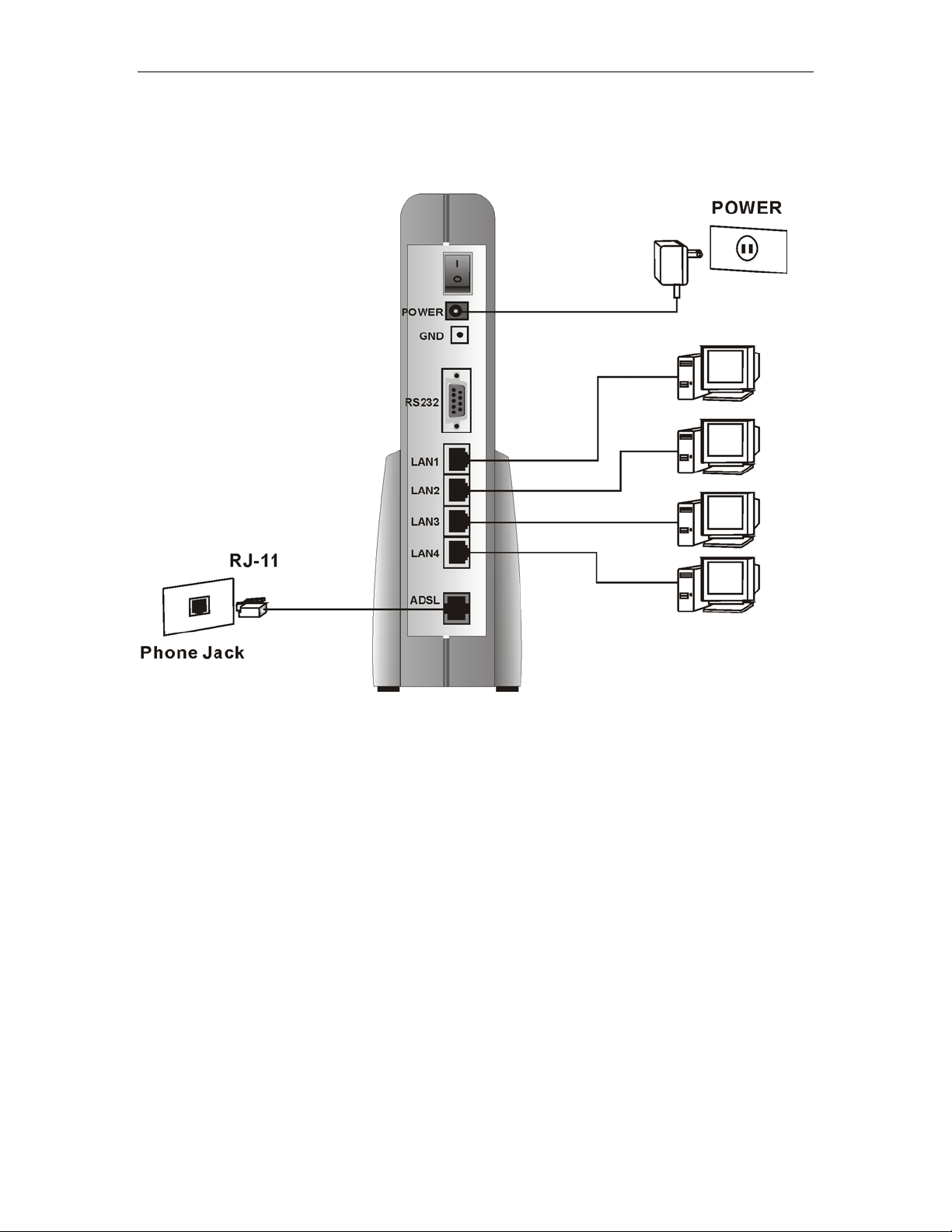
1.4 Rear Panel
The rear panel of the ADSL Router consist of power jack, Console
Port connector, Ethernet connections and ADSL phone socket as
below:
Function Definition
1/0 Power on/off switch
POWER The power jack connects to 12VDC Adapter from wall outlet.
RS232 This is RS232C interface and is used to manage the ADSL
Router.
LAN1,
10/100 Ethernet interfaces to connect to PC.
LAN2,
LAN3,
LAN4
ADSL ADSL jack connect to DSL line from TelCo
12
Solwise SAR715PV ADSL Ethernet Router User’s Guide Chapter 2. Connecting to your network and line
2 Connecting to your network and line
LAN ports LAN1 to LAN4 on the SAR715PV router are the type
designed to be connected to directly to the port on a PC LAN card
using a standard cat5 LAN cable. If you wish to connect the router
to another hub then you must connect to the uplink port of the
second hub or use a cross over cable to a normal port on the hub.
Use the supplied RJ11 phone cable to connect from the ADSL
socket on your router to your ADSL phone socket.
Connect the power jack from the power supply to the power socket
on the router and then plug the power supply into a suitable UK
power socket: The green POWER LED on the front of the router
should light up.
If you want to do configuration via the Command Line Interface
using Telnet then you can connect using the standard user name
‘admin’ and password ‘admin’ and the default IP address of the
router is 192.168.0.1. If you want to use CLI mode via the serial port
then you’ll need to connect a 9pin serial cable to the RS232
connector on the back of the router (a ‘normal’ modem, serial cable
is required which can be purchased from your supplier if needed).
Port settings are 9600,8,1,n,no flowcontrol.
13

Chapter 2. Connecting to your network and line Solwise SAR715PV ADSL Ethernet Router User’s Guide
Alternatively a more user friendly configuration method is to
use the built in http interface. To do this all you need to do to
be able to do is access the router through your web browser
running on any computer.
14

Solwise SAR715PV ADSL Ethernet Router User’s Guide Chapter 3. Setting up TCP/IP on your computer
3 Setting up TCP/IP on your computer
You first of all need to check the TCP/IP settings of your computer.
Please note that the author is assuming you are using MS Windows
(Win9x or 2K/XP) or Mac OS10; please make appropriate
allowances if using another operating system or platform such as
Linux. The default IP address of the SAR router is 192.168.0.1 on
subnet mask 255.255.255.0. In simple terms this means that, in
order for your computer to talk to the router, their IP address should
be in the range from 192.168.0.2 to 192.168.0.254. If you already
use TCP as your default network protocol and you don’t use IP
settings in the required range then you will have to either
permanently alter the settings of your computers to suite or change
the default address of the router. If you wish to alter the settings of
all your computers to suite then it is probably best to ask the person
in charge of your network set-up to do this for you. If you want to
alter the router then you will have to temporarily change the settings
for your PC.
3.1 Installing TCP protocol on your PC
Win9x Win2K/XP
Go to Start/Settings/Control Panel/Network....
Go to Start/Settings/Network and Dialup Connections...
Click on ‘Local Area Connection’.
If you already see a line showing TCP/IP protocol such as
the example shown above then you can skip this section.
Otherwise click on Add, then select Protocol and then click
on Add.. again. Then on the Select Network Protocol
screen select Microsoft/TCP/IP...
15

Chapter 3. Setting up TCP/IP on your computer Solwise SAR715PV ADSL Ethernet Router User’s Guide
Click on OK and Windows will then add the protocol to your network setup.
Then on Properties..
If you already see a line showing TCP/IP protocol such as
the example shown above then you can skip this section.
Otherwise click on Install, then select Protocol and then
click on Add.
Then on the Select Network Protocol screen select
Microsoft/TCP/IP...
Click on OK and Windows will then add the protocol to
your network set-up.
16

Solwise SAR715PV ADSL Ethernet Router User’s Guide Chapter 3. Setting up TCP/IP on your computer
3.2 Configuring TCP/IP Protocol for your PC
Go to Start/Settings/Control Panel/Network....
Scroll down the list of network settings until you find the
entry showing TCP/IP. There may be several such entries
(see example); the one you need is the entry associated
with your network card. Select it and then click on
Properties:
Go to your local network settings (Start/Settings/Network
and Dialup Connections/Local Area
Connection/Properties).
Scroll down the list of network settings until you find the
entry showing TCP/IP. Select it and then click on
Properties:
The first screen shows the IP Address for your PC. As
already explained, you need to ensure that each PC on
your LAN has an IP address which is both unique and
within the subnet range of the routers address e.g. in the
range 192.168.0.2 to 192.168.0.254 (assuming default IP
address for the router).
Next, for each PC you must enter a Gateway address. This
is the address of the router and tells your PC where to
send internet TCP requests:
17
As already explained, you need to ensure that each PC on
your LAN has an IP address which is both unique and
within the subnet range of the routers address e.g. in the
range 192.168.0.2 to 192.168.0.254 (assuming default IP
address for the router).
Now you need to enter the address of the router as the
default gateway.

Chapter 3. Setting up TCP/IP on your computer Solwise SAR715PV ADSL Ethernet Router User’s Guide
Finally you must set-up DNS Configuration on each PC:
Each PC MUST have the address for DNS entered in it’s
TCP setting. If your PC doesn’t have a DNS setting then it
will not be able to find any internet sites so it’s important
that you have this set correctly!
On the DNS Configuration screen you must Enable DNS
and then enter a Host name; this can be anything you like
– just a made up name will do!
Now you need to enter the DNS address.
Each PC MUST have the address for DNS entered in it’s
TCP setting. If your PC doesn’t have a DNS setting then it
will not be able to find any internet sites so it’s important
that you have this set correctly!
On the main TCP/IP Properties screen select ‘Use the
following DNS server addresses’.
Now you need to enter an address for the ‘Preferred DNS’.
Ideally you should get the DNS address to use from your
ISP (a list showing some of the common ISP DNS
addresses is given below). However, if you don’t know the
ISPs’ DNS address then you can temporarily use the
address 212.50.160.100.
Enter the DNS address for the preferred DNS (as shown
above).
Finally click on OK, then OK and then Close. The new
TCP/IP settings should take immediate effect.,
18
That’s all there is to the basic set-up.

Solwise SAR715PV ADSL Ethernet Router User’s Guide Chapter 3. Setting up TCP/IP on your computer
Ideally you should get the DNS address to use from your
ISP (a list of common addresses is given later). However, if
you don’t know the ISPs’ DNS address then you can
temporarily use the address 212.50.160.100 or
1212.50.160.28. You need to ‘add’ the DNS address to the
DNS list.
Finally click on OK and then OK from the main Network
menu.
Windows will now install the revised network settings;
please note that your original Windows installation CD
might be required. You should then reboot your PC.
That’s all there is to the basic set-up.
3.3 Setting up TCP/IP protocol on your Mac
Configuration of the router is done using your web browser but first
of all you need to ensure that the IP settings on computer are
correctly set to enable you to talk with the router. The default IP
address of the Asus router is 192.168.0.1 with netmask
255.255.255.0. This means your computers and other network
resources should have IP address’s in the range 192.168.0.2 to
192.168.0.254. First of all go to the Network set-up on your Mac:
19

Chapter 3. Setting up TCP/IP on your computer Solwise SAR715PV ADSL Ethernet Router User’s Guide
Enter a suitable IP address (e.g. 192.168.0.2) and the netmask as
shown above and click on Apply Now.
Now enter the IP address of the router in ‘Router’ box.
20
You also need to enter an address for your ‘Domain Name Server’.

Solwise SAR715PV ADSL Ethernet Router User’s Guide Chapter 3. Setting up TCP/IP on your computer
Ideally you should get the DNS address to use from your ISP.
However, if you don’t know the ISPs’ DNS address then you can
temporarily use the address 212.50.160.100.
Add the DSN address to the Domain Name Server list.
That’s all you should have to do. Click on Apply Now and your new
settings should be set.
21

Chapter 4. Quick Router configuration using your browser Solwise SAR715PV ADSL Ethernet Router User’s Guide
4 Quick Router configuration using your browser
The easiest way to configure your router is via your web browser
accessing the html pages direct in the router.
To configure using your browser you must first of all must have
successfully installed TCP/IP protocol on your computer as detailed
above.
After checking your connections and TCP settings (see above) you
are ready to run your browser in order to configure the router.
Please note the following:
The default IP address for the 8.2 firmware is 192.168.0.1
The default configuration username and password are admin.
Any browser can be used on any operating system: The
configuration screens are the same.
Note: If you are using Explorer on a PC then first
check that your browser is set to use LAN for internet
access. To do this in Explorer go to Tools/Internet
Options/Connections. Then check that the setting
‘Never dial a connection’ is selected. Then on the LAN
Settings screen nothing should be ticked.
Now start your browser and enter the address of the router on the
Address/URL line of your browser (192.168.0.1). The browser
should then load the start-up page from the router:
If it asks for a Username/Password to enter configuration then use
‘admin’ and ‘admin’….
22

Solwise SAR715PV ADSL Ethernet Router User’s Guide Chapter 4. Quick Router configuration using your browser
4.1 What you see on the Start-up page
Status : This page shows the status of your connection.
Quick Start : This page allows you to set up authentication & login
details which may be required by your ISP
23

Chapter 4. Quick Router configuration using your browser Solwise SAR715PV ADSL Ethernet Router User’s Guide
System :
1. Error Log : This page shows recent configuration errors
from your router
2. Remote Access : This page allows you to setup remote
configuration options
3. Upgrade : From this page you may upgrade the system
software on your network device
4. Restart : From this page you may restart your router
Configuration :
1. Save config : Use this page to commit changes to system
memory.
2. Authentication : This page allows you to control access to
your router's console and these configuration web-pages.
3. LAN connections : Use this page to set the LAN
configuration, which determines how your device is identified on
the network.
4. WAN connections : This option allows you to create and
configure WAN connections from your router
5. IP routes :
6. DHCP server : Allows you to enable, disable and configure
your DHCP server
7. DNS client :
client
8. DNS relay :
relay
9. Security :
Intrusion Detection.
10. IPSec: Allows you to setup the IPSec Gateway settings,
Endpoint Configuration and security certificates.
11. PPTP: Allows you configure the PPTP IP pool and user
authentication.
12. L2TP: Allows you configure the L2TP IP pool and user
authentication.
13. Syslog: Allows you to set the Syslog message level and specify
settings for the Syslog client.
14. SNMP: Allows you configure SNMP management settings.
15. Ports: Allows you to configure the ports available from your
router
Allows you to create, edit and delete IP routes.
Allows you to enable, disable and configure DNS
Allows you to enable, disable and configure DNS
Allows you to configure Security, Firewall, NAT and
24
a. ADSL: Allows you to view the stats for the ADSL port
and also to modify the ADSL port parameters (DON’T
touch these unless you know what you are doing!).
Ethernet: Allows you to view the stats for the ethernet LAN port and
also to modify the port parameters (DON’T touch these unless you
know what you are doing!).

Solwise SAR715PV ADSL Ethernet Router User’s Guide Chapter 4. Quick Router configuration using your browser
4.1.1 About the Status Page
The Status homepage contains information about the current
configuration of this router. It provides an overview of the current
image configuration. The page contains the following sections:
• Status
• Advanced Diagnostics
Status
The Status section displays:
• PPPoA Connection status (connected or disconnected)
• The current WAN IP Address configuration. It also provides a
WAN Settings hyperlink that allows you to create, modify or
delete your WAN configuration.
• The current Local IP Address configuration. It also provides a
LAN Settings hyperlink that allows you to create, modify or
delete your LAN configuration.
Advanced Diagnostics
The Advanced Diagnostics section displays:
25

Chapter 4. Quick Router configuration using your browser Solwise SAR715PV ADSL Ethernet Router User’s Guide
• Connection Authentication details; this displays details about
your current ISP login settings. It also provides a Login
Settings hyperlink that allows you to create, modify or delete
your existing
• login setup.
• Port Connection Status
• WAN Status
• LAN Status
• Hardware Status
• Defined Interfaces
Port Connection Status
This section displays information about your port connections:
• Port; the ports available on this ADSL router
• Type; the kind of traffic that can be transported on each port
• Connected; which of the ports on this ADSL router are
currently connected:
•
•
represents a port that is not connected
represents a port that is connected
• Line State; DSL connection status
WAN Status
This section displays the following status information about your
WAN configuration:
• IP Address Type; whether the WAN IP address is used or the
address is obtained dynamically from DHCP.
• WAN Subnet Mask
• Default Gateway; whether DHCP server has been
configured to give out the WAN IP address as the default
Gateway address.
• Primary DNS; whether a Primary DNS IP address has been
set.
The WAN Status section also provides two hyperlinks:
• IP Address Settings; this allows you to create, modify or
delete your WAN configuration.
• DNS Client Settings; this allows you to create, modify or
delete your DNS Client configuration.
26
LAN Status
This section displays the following status information about your
Local Area Network settings:
• LAN Subnet Mask

Solwise SAR715PV ADSL Ethernet Router User’s Guide Chapter 4. Quick Router configuration using your browser
• Act as Local DHCP Server (Yes/No)
• MAC Address; this is the actual MAC address for the
Ethernet block in this router.
The LAN Status section also provides a DHCP Server Settings
hyperlink that allows you to configure your DHCP server status.
Hardware Status
This section displays the following status information about your
ADSL router:
• Up-Time; the length of time (in hours:minutes:seconds) that
your current session has been connected for
• Version; information about the software release which has
been used to build the image running on your ADSL router.
• Vendor; The name of the Vendor supplying the ADSL
router. The default setting for this is GlobespanVirata.
Defined Interfaces
This section lists LAN interfaces that have been defined
Each interface listed has a Show Statistics hyperlink associated with
it. Click on this for detailed information about some/all of the
following (depending on the interface type and configuration):
• the interface
• connection details
• port configuration
• service parameters
4.2 Setting up a basic NAT router configuration
Please note the following:
The default IP address for the 8.2 firmware is 192.168.0.1
The default configuration username and password are admin.
4.2.1 Clearing to factory defaults
Make sure your PC is on an IP address in the same subnet as the
715PV (e.g. 192.168.0.2). Next, enter the address of the router in
your browser address line (i.e. 192.168.0.1)…
The main status page for the router should display.
27

Chapter 4. Quick Router configuration using your browser Solwise SAR715PV ADSL Ethernet Router User’s Guide
First of all you are advised to ensure the router is reset to factory
default settings. To do this goto System/Restart and, to enter
configuration, enter admin for username and password…..
28

Solwise SAR715PV ADSL Ethernet Router User’s Guide Chapter 4. Quick Router configuration using your browser
Tick the box ‘Reset to factory defaults’ then click on Restart.
Now wait for about 30 seconds whilst the router resets and then
click on Status to re-display the front page…
29

Chapter 4. Quick Router configuration using your browser Solwise SAR715PV ADSL Ethernet Router User’s Guide
4.2.2 Creating a PPPoA WAN connection for the UK
The quick way to setup a your router for internet access is to modify
the existing PPPoA settings. To do this, from the main Status page,
click on the ‘WAN Settings’ link where it says ‘PPPoA Connections’
(at the top of the page).
Now click on ‘Edit’ on the ppp-0 entry…
30

Solwise SAR715PV ADSL Ethernet Router User’s Guide Chapter 4. Quick Router configuration using your browser
4.2.2.1 Settings for a BT phone line
First of all you need to alter the PPP settings so now click on the
‘Edit PPP’ link…
Below shows the configuration settings displayed under the Edit
PPP tab.
The majority of these settings can be left as default but the following
must be changed..
31

Chapter 4. Quick Router configuration using your browser Solwise SAR715PV ADSL Ethernet Router User’s Guide
‘Dialout Username’ must be your login name for your internet
account
‘Dialout Password’ and ‘Confirmation Password’ must be the
login password for your internet account. Please note, even if your
ISP doesn’t provide you with a password you MUST enter one:
Make one up ☺
‘Dialout Auth’ must be set to Chap
‘Auto Connect’ should be set to true
e.g. as shown below….
Name Value
Server:
Create Route:
Specific Route:
Subnet Mask:
Route Mask:
Hdlc:
LLC:
Lcp Max Configure:
Lcp Max Failure:
false
true
false
0.0.0.0
0.0.0.0
false
false
10
5
32
Lcp Max Terminate:
Dialin Auth:
Dialout Username:
Dialout Password:
2
none
fred
test

Solwise SAR715PV ADSL Ethernet Router User’s Guide Chapter 4. Quick Router configuration using your browser
Confirmation Password:
Dialout Auth:
Interface ID:
Remote Ip:
Local Ip:
Magic Number:
MRU:
Ip Addr From IPCP:
Discover Primary DNS:
test
chap
1
0.0.0.0
0.0.0.0
0
0
true
true
Discover Secondary DNS:
Give DNSto Relay:
Give DNSto Client:
Remote DNS:
Remote Secondary DNS:
Lcp Echo Every:
Auto Connect:
Idle Timeout:
true
true
true
0.0.0.0
0.0.0.0
10
true
0
33

Chapter 4. Quick Router configuration using your browser Solwise SAR715PV ADSL Ethernet Router User’s Guide
Enabled:
true
Then click on ‘Change’ at the bottom of the screen to store the
settings.
Next you need to alter the ATM settings so now click on the ‘Edit
ATM’ link…
34
Below shows the configuration settings displayed under the Edit
ATM tab.
The following must be changed..
‘Tx Vci’ should be set to 38
‘Tx Vpi’ should be set to 0
‘Rx Vci’ should be set to 38
‘Rx Vpi’ should be set to 0
e.g. as shown below….
Name Value
Tx Vci:
38

Solwise SAR715PV ADSL Ethernet Router User’s Guide Chapter 4. Quick Router configuration using your browser
Tx Vpi:
Rx Vci:
Rx Vpi:
Peak Cell Rate:
Burst Tolerance:
MCR:
MBS:
Sustainable Cell Rate:
Class:
0
38
0
2000
0
0
0
0
UBR
Port:
Then click on ‘Change’ at the bottom of the screen to store the
settings.
That completes setting the PPoA settings for your internet
connection.
4.2.2.2 Settings for a KC phone line
First of all you need to alter the PPP settings so now click on the
‘Edit PPP’ link…
a1
35

Chapter 4. Quick Router configuration using your browser Solwise SAR715PV ADSL Ethernet Router User’s Guide
Below shows the configuration settings displayed under the Edit
PPP tab.
The majority of these settings can be left as default but the following
must be changed..
‘LLC’ must be set to true.
‘Dialout Username’ must be your login name for your internet
account
‘Dialout Password’ and ‘Confirmation Password’ must be the
login password for your internet account
‘Dialout Auth’ must be set to Chap
‘Auto Connect’ should be set to true
e.g. as shown below….
Name Value
Server:
Create Route:
false
true
36
Specific Route:
false

Solwise SAR715PV ADSL Ethernet Router User’s Guide Chapter 4. Quick Router configuration using your browser
Subnet Mask:
Route Mask:
Hdlc:
LLC:
Lcp Max Configure:
Lcp Max Failure:
Lcp Max Terminate:
Dialin Auth:
Dialout Username:
0.0.0.0
0.0.0.0
false
true
10
5
2
none
fred
Dialout Password:
Confirmation Password:
Dialout Auth:
Interface ID:
Remote Ip:
Local Ip:
Magic Number:
MRU:
Ip Addr From IPCP:
test
test
chap
1
0.0.0.0
0.0.0.0
0
0
true
37

Chapter 4. Quick Router configuration using your browser Solwise SAR715PV ADSL Ethernet Router User’s Guide
Discover Primary DNS:
Discover Secondary DNS:
Give DNSto Relay:
Give DNSto Client:
Remote DNS:
Remote Secondary DNS:
Lcp Echo Every:
Auto Connect:
Idle Timeout:
true
true
true
true
0.0.0.0
0.0.0.0
10
true
0
Enabled:
true
Then click on ‘Change’ at the bottom of the screen to store the
settings.
Next you need to alter the ATM settings so now click on the ‘Edit
ATM’ link…
38

Solwise SAR715PV ADSL Ethernet Router User’s Guide Chapter 4. Quick Router configuration using your browser
Below shows the configuration settings displayed under the Edit
ATM tab.
The following must be changed..
‘Tx Vci’ should be set to 50
‘Tx Vpi’ should be set to 1
‘Rx Vci’ should be set to 50
‘Rx Vpi’ should be set to 1
e.g. as shown below….
Name Value
Tx Vci:
Tx Vpi:
Rx Vci:
50
1
50
Rx Vpi:
39
1

Chapter 4. Quick Router configuration using your browser Solwise SAR715PV ADSL Ethernet Router User’s Guide
Peak Cell Rate:
Burst Tolerance:
MCR:
MBS:
Sustainable Cell Rate:
Class:
Port:
2000
0
0
0
0
UBR
a1
Then click on ‘Change’ at the bottom of the screen to store the
settings.
That completes setting the PPoA settings for your internet
connection.
4.2.3 Creating a PPPoE WAN connection for Ireland & France
From the Status page (as shown above) click on WAN Settings
(where it says Status at the top of the page):
First of all Delete any existing services shown.
40

Solwise SAR715PV ADSL Ethernet Router User’s Guide Chapter 4. Quick Router configuration using your browser
Then click on ‘Create a new service’…
Tick "PPPoE routed" and Configure.
41

Chapter 4. Quick Router configuration using your browser Solwise SAR715PV ADSL Ethernet Router User’s Guide
Enter the details required: Put a name for the Description (maybe
the name of your ISP), then put in the correct VPI/VCI values (for
France and Eirecom use 8/35 for these values). Select CHAP and
enter the correct user name/password for your ISP – please note,
even if your account does not have a password you MUST still
enter a dummy password (e.g. ‘fred’ ☺).
4.2.4 Disabling DHCP Server
All the other parameters can be left as default values (as shown
above) and then click on Configure.
It’s easier if, for now, you disable DHCP server (details on how to
configure DHCP server setup are given later).
Click on Configuration/DHCP server.
42

Solwise SAR715PV ADSL Ethernet Router User’s Guide Chapter 4. Quick Router configuration using your browser
Select ‘Disabled’ and then click Configure.
Now click on Apply.
43

Chapter 4. Quick Router configuration using your browser Solwise SAR715PV ADSL Ethernet Router User’s Guide
4.2.5 Saving the configuration and restarting
To store you new configuration click on Configuration/Save config…
Click on Save.
Wait until you get a message confirming saved.
Next, to restart the router click on System/Restart
44
Then click on Restart. Wait about 30 seconds for the router to
reboot and then click on Status.

Solwise SAR715PV ADSL Ethernet Router User’s Guide Chapter 4. Quick Router configuration using your browser
4.2.6 Testing the connection
Goto the Status page.
Now, if you are correctly connected to the line the ADSL Status
there should be a WAN IP Address shown at the top under PPPoA
Connections.
To get the full connection statistics goto the bottom of the page and
click on ‘Show Statistics’ for your new WAN interface under ‘Defined
Interfaces’.
45

Chapter 4. Quick Router configuration using your browser Solwise SAR715PV ADSL Ethernet Router User’s Guide
For a proper connection the IP Address at the top of the page must
be shown; 0.0.0.0 means the router is not logged in with the ISP.
Under the ‘PPPoA parameters’ the Status should show open for IP.
Now your connection should be up and working (check your TCP
set-up is set for the new address of the router – 192.168.0.1 - and
your other TCP settings are correct)!!!
46

Solwise SAR715PV ADSL Ethernet Router User’s Guide Chapter 5. The Configuration Screens in More Detail
5 The Configuration Screens in More Detail
5.1 About the System menu
The System menu contains options which allow low-level changes to
be made, such as updating the image on the system. From the lefthand menu, click on System. The following sub-headings are
displayed:
• Error log; displays information about recent configuration errors.
• Remote Access; allows you to enable remote administration of your
ADSL router (using NAT).
• Upgrade; allows you to update the image on your ADSL router.
• Restart; allows you to restart your ADSL router and optionally
restore factory defaults.
5.1.1 Error Log
From the System menu, click on Error Log. The following page is
displayed:
This page displays a table containing all configuration errors
experienced by your ADSL router during a current session. The
table also tells you:
• when the error occurred (in seconds since your system was
restarted)
• which process the error occurred in.
5.1.2 Remote Access
This allows you to enable temporary remote access to your ADSL
router using Network Address Translation (NAT):
47

Chapter 5. The Configuration Screens in More Detail Solwise SAR715PV ADSL Ethernet Router User’s Guide
1. From the System menu, click on Remote Access. Before you can
enable remote access, you must configure NAT. Click on the NAT
hyperlink, or click on Configuration>Security from the left-hand menu.
2. Once you have configured NAT, click on Remote Access to display
the following:
3. Type in the length of time that you want to allow remote access
for. Click on Enable.
5.1.3 Upgrade
4 The Remote Access page is displayed, confirming the number of
seconds remaining for remote access. There is also a Disable
button that allows you to stop remote access before the specified
time ends.
This option allows you to upload firmware images to the ADSL
router using HTTP. A tar archive is uploaded to the RAM of your
ADSL router. The archive is unpacked automatically, files are
validated and then written to Flash memory.
From the System menu, click Upgrade. The following page is
displayed:
48

Solwise SAR715PV ADSL Ethernet Router User’s Guide Chapter 5. The Configuration Screens in More Detail
2. Type in the network location of the new firmware image that you
want to upload, or use the Browse button to browse through the
network and select the file. Click on Upgrade.
3. Once the file has been uploaded to the RAM of your ADSL
router, it is written to Flash. A status page is displayed confirming
that the upload is complete and telling you how much of the file (in
bytes and as a percentage) has been written to Flash.
4. Once the file has been written to Flash, the Firmware Upgrade
page is refreshed. The page confirms completion of the update and
asks you to restart your ADSL router in order to use the new
firmware. Click on Restart.
Note – Upgrading your firmware could take up to 15 minutes to
complete.
5.1.4 Restart
This page allows you to restart your ADSL router. It has the same
effect as resetting your ADSL router by pressing the appropriate
reset button on the hardware.
To restart your system:
1. From the System menu, click on Restart. The following page
is displayed:
2. Click on the Restart button to reset the ADSL router. The
Restart page also provides you with the option of restarting
and restoring the factory default settings. Click in the Reset
to factory default settings box to check it, then click on the
Restart button. Read the console status output to check how
the reset is progressing.
3. Once the login and password prompt is displayed at the
console, you can login as usual (with login = admin,
password = admin), then refresh the browser that is
running. The Status page is displayed and your ADSL router
has been reset.
49

Chapter 5. The Configuration Screens in More Detail Solwise SAR715PV ADSL Ethernet Router User’s Guide
5.2 Configuration
The Configuration menu contains options for configuring features on
your ADSL router including basic LAN and WAN connections and
DHCP and DNS settings. Most of the features contain sensible
default settings. You are unlikely to have to reconfigure every
feature included in the Configuration menu.
From the left-hand menu, click on Configuration. The following subheadings are displayed:
• Save config; allows you to save your current configuration to Flash
memory.
• Authentication; allows you to create, edit and delete user accounts.
• LAN connections; allows you to edit your LAN port IP address,
create and edit a secondary IP address and create new LAN
services.
• WAN connections; allows you to create, edit and delete WAN
services.
• IP routes; allows you to create, edit and delete IP routes.
5.2.1 Save configuration
• DHCP server; allows you to enable, disable and configure your
DHCP server.
• DNS client; allows you to enable, disable and configure DNS client.
• DNS relay; allows you to enable, disable and configure DNS relay.
• Security; allows you to configure Security, Firewall, NAT and
Intrusion Detection.
• SNTP client; allows you to enable, disable and configure SNTP
client.
• Ports; allows you to configure the ports available on your ADSL
router.
To save your current configuration to Flash memory:
1. From the Configuration menu, click on Save config. The following
page is displayed:
50

Solwise SAR715PV ADSL Ethernet Router User’s Guide Chapter 5. The Configuration Screens in More Detail
2. Click on the Save button to save your current configuration to
flash.
5.2.2 Authentication
After a short time the configuration is saved and the following
confirmation message is displayed:
Saved information model to file //flashfs/im.conf
This option allows you to administer accounts for users who access
the ADSL router. To create, edit or delete user accounts:
1. From the Configuration menu, click on Authentication. The
following page is displayed:
2. The Authentication page contains a table showing all current login
accounts. It contains the following information:
User name
51

Chapter 5. The Configuration Screens in More Detail Solwise SAR715PV ADSL Ethernet Router User’s Guide
May login? status; whether the user can login to the
system (true) or dialin to the system (false)
Comment describing the user (optionally added when an
account is created)
3. To create a new login account:
Click on the Create a new user button. The following page is
displayed:
Type details for the new user into the username,
password and comment text boxes, and select a May
login? option:
true means that the user can login but not dialin
false means that the user can dialin but not login
Click on the Create button. The Authentication page is
displayed. The table now contains details for the user that
you have just created.
The Authentication page table contains an Edit user hyperlink for
each user account entry. Click on a link. The following page is
displayed:
5.2.3 LAN Connections
52
This page allows you to:
• update details for a specific user account. Modify the necessary
text boxes then click on the Apply button.
• delete a user account. Click on the Delete this user button.
Once you have edited or deleted a user account. the Authentication
page is displayed and the table reflects any changes that you have
made on the edit user page.
This option allows you to:
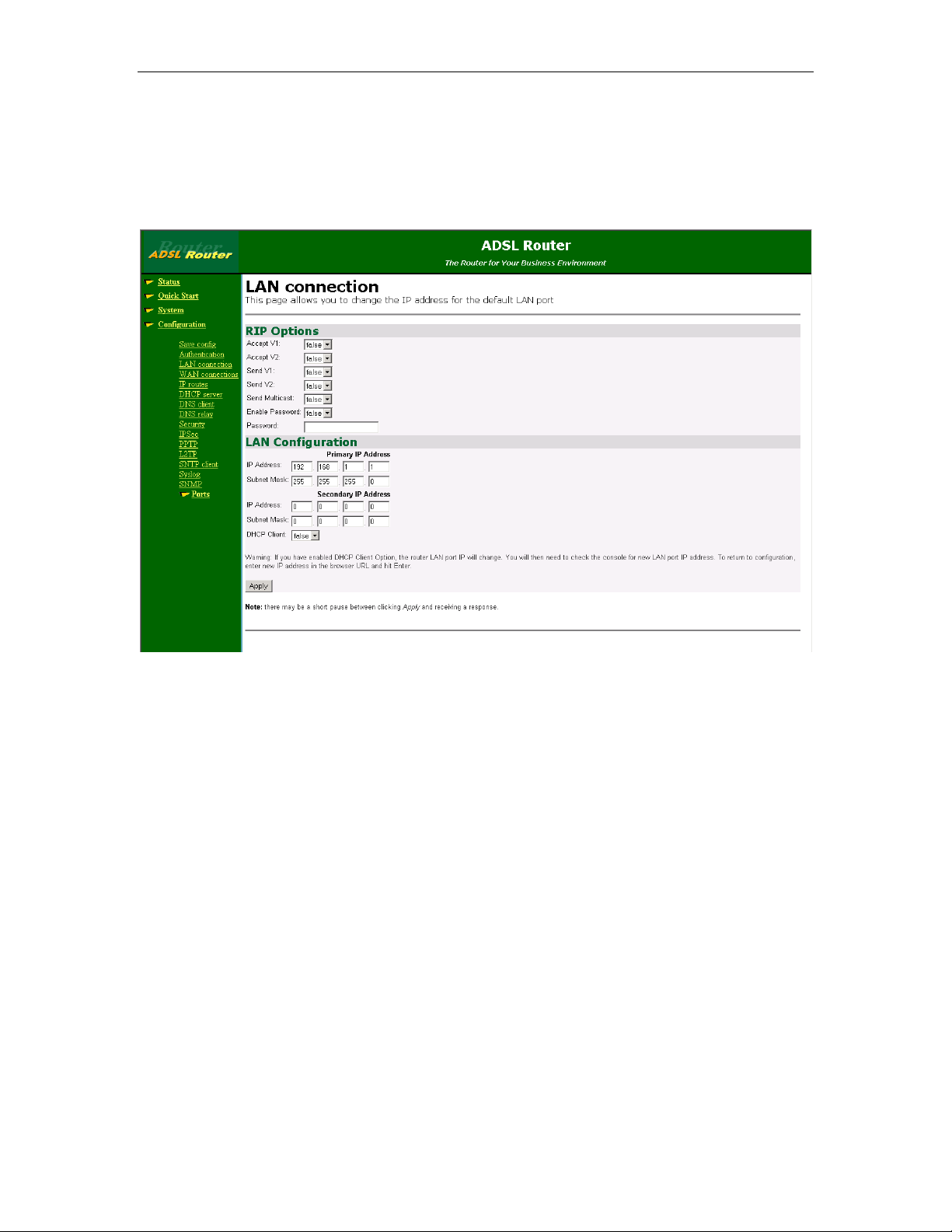
Solwise SAR715PV ADSL Ethernet Router User’s Guide Chapter 5. The Configuration Screens in More Detail
• configure the IP address and subnet of the default LAN connection
to the ADSL router.
• configure the RIP Options.
1. From the Configuration menu, click on LAN connections. The
following page is displayed:
5.2.4 WAN Connections
2. This page displays a table that displays the current IP address
settings for the ethernet LAN port. You can also alter the options
for RIP routing (alter these with care).
To update your primary or secondary IP address:
1. At the LAN connections page, click on the change default LAN port
IP address button. The following page is displayed:
2. configure the Primary IP address and subnet mask for the IP
interface.
3. create or configure a Secondary IP address and Subnet mask for
the interface.
4. A Secondary IP address is usually used if you have defined two
subnets on a LAN and wish to route them through the same IP
interface.
5. Once you have configured your address(es), click on the Apply
button. A message is displayed confirming that your address
information is being updated. You may need to enter the IP address
in your web browser address box.
This option allows you to create and configure WAN connections for
your ADSL router.
53

Chapter 5. The Configuration Screens in More Detail Solwise SAR715PV ADSL Ethernet Router User’s Guide
1. From the Configuration menu, click on WAN connections. The WAN
connections page is displayed:
2. This page contains a table that displays the current WAN
connections or services which have been defined. To define a new
WAN service:
5.2.5 IP Routes
a. Click on Create a new service A page is displayed containing
a list of WAN service options. The options available on this
page are determined by the image which is running on the
ADSL router.
b. Select an option, then click on Configure. You need to add
detailed configuration information about the WAN service that
you are creating.
c. Click on Apply. The WAN connections page is displayed. The
table now contains details of the service that you have just
created.
3. Each service on the WAN connections page has an Edit and a
Delete link associated with it. To edit a service:
a. Click on the Edit link.
b. Change the values for the existing service, then click on
Change. The page is reset and the new values are displayed.
To delete a service:
a. Click on the Delete link.
b. Check the details displayed, then click on the Delete this
connection button.
54
This option allows you to create static IP routes to destination
addresses via an IP interface name or a Gateway address. From
the Configuration menu, click on IP routes. The Edit Routes page is
displayed:

Solwise SAR715PV ADSL Ethernet Router User’s Guide Chapter 5. The Configuration Screens in More Detail
This page lists the following information about existing routes:
• Destination IP address
• Gateway address
• Netmask address
This page also allows you to:
• Edit the destination, gateway and netmask address of a route.
Click in the relevant text box, update the information then click on
Apply.
• Edit the cost and interface setting for the route. Click on the
Advanced Options hyperlink for a specific route, and update the
relevant information. Click on OK.
• Create a new IP V4 Route.
To create a route:
1. Click on the Create new Ip V4 Route hyperlink. The following page
is displayed:
2. Complete the Create IP v4 Route form in order to configure the
route.
3. When you have entered all the details, click on OK. The Edit
Routes page is displayed. The table now contains details of the route
that you have just created.
55

Chapter 5. The Configuration Screens in More Detail Solwise SAR715PV ADSL Ethernet Router User’s Guide
5.2.6 DHCP Server
This option allows you to enable and configure the DHCP server on
your ADSL router.
From the Configuration menu, click on DHCP server. The following
page is displayed:
The DHCP server page displays the current status of the DHCP
server. The values listed above are the default settings for DHCP
server. Once the DHCP server or Relay is enabled, information
about any subnets which have been defined will also be displayed.
To change the configuration of the DHCP server, click on Configure.
The following page is displayed:
56

Solwise SAR715PV ADSL Ethernet Router User’s Guide Chapter 5. The Configuration Screens in More Detail
This page allows you to:
• Set the DHCP address range (or use a default range of 20
addresses).
• Set the global default and maximum lease times.
• Set your ADSL router to give out its own IP address as the DNS
Server address.
• Set the Primary and Secondary DNS Server addresses.
• Set your ADSL router to give out its own IP address as the default
Gateway address.
Once you have entered new configuration details for your DHCP
server, click on Apply.
If you want to carry out further configuration of your DHCP Server,
click on the Advanced Options page at the bottom of the DHCP
configuration page. The following page is displayed:
57

Chapter 5. The Configuration Screens in More Detail Solwise SAR715PV ADSL Ethernet Router User’s Guide
This page allows you to edit the options that appear on the DHCP
Server page.
5.2.7 DNS Client
This option allows you to:
• create a list of server addresses. This enables you to retrieve a
domain name for a given IP address.
• create a domain search list. DNS client uses this list when a user
asks for the IP address list for an incomplete domain name.
From the Configuration menu, click on DNS client. The following
page is displayed:
58
To configure DNS servers:
1. Type the IP address of the unknown domain name in the DNS
servers: text box.

Solwise SAR715PV ADSL Ethernet Router User’s Guide Chapter 5. The Configuration Screens in More Detail
2. Click on Add. The IP address appears in the DNS servers table.
You can add a maximum of three server IP addresses. Each IP
address entry has a Delete button associated with it. Click on Delete
to remove an IP address from this list.
To configure DNS search domains:
1.Type a search string in the Domain search order: text box.
2.Click on Add. The search string is displayed in the Domain search
order table. You can add a maximum of six search strings. Each
search string entry has a Delete button associated with it. Click on
Delete to remove a string from this list.
5.2.8 DNS Relay
This option allows you to enable, disable and configure DNS relay.
From the Configuration menu, click on DNS relay. The following page
is displayed:
The default setting for DNS relay is disabled. To enable and
configure DNS relay:
1. Click on the Enabled radio button.
2. Click on the Configure button. The following page is displayed:
59

Chapter 5. The Configuration Screens in More Detail Solwise SAR715PV ADSL Ethernet Router User’s Guide
This page allows you to add the IP address of a DNS Server to
DNS relay’s list of server IP addresses.
3. Type an IP address in the DNS server IP address text box. Click on
the Apply button.
5.2.9 Security
The Configure the DNS relay button displays the configuration page
and allows you to disable or configure a new DNS relay address.
This option allows you to configure Security, NAT and Firewall:
• Security - allows you to:
• enable Security.
• configure Security interfaces.
• configure triggers.
• NAT - allows you to:
• enable NAT between interfaces.
• configure global addresses.
• configure reserved mapping.
• Firewall - allows you to:
• enable Firewall and Firewall Intrusion Detection settings.
• set the Firewall security level.
• configure Firewall policies, portfilters and validators.
• configure Intrusion Detection settings.
60
• configure Alerting.
From the Configuration menu, click on Security. The following page is
displayed:

Solwise SAR715PV ADSL Ethernet Router User’s Guide Chapter 5. The Configuration Screens in More Detail
This page contains the default Security settings.
Enabling Security
You must enable Security before you can enable Firewall and/or
Intrusion Detection. With NAT enabled Security is enabled by default.
In the Security State section:
Click on the Security Enabled radio button.
1.
2. Click on Change State to update the Security State section.
Enabling Firewall and/or Intrusion Detection
You must create a security interface before you can enable Firewall
and/or Intrusion Detection.
Once you have created a security interface:
1. Click on the Firewall Enabled and/or Intrusion Detection
Enabled radio buttons.
2. Click on Change State to update the Security State section.
Setting a default security level
You must have Security and Firewall enabled in order to set a
default Security level.
1. From the Security Level section, click on the Security Level drop-
down list.
61

Chapter 5. The Configuration Screens in More Detail Solwise SAR715PV ADSL Ethernet Router User’s Guide
2. Click on the level that you want to set; none, high, medium or
low.
3. Click on the Change Level button.
Configuring security interfaces
Security interfaces are based on existing LAN services. You must
create a LAN service for every security interface that you want to
configure.
1. From the Security Interfaces section, click on Add Interface. The
Firewall: Add Interface page is displayed:
2. Click on the Name drop-down list and select the LAN service that
you want to base your security interface on.
3. Click on the Interface Type drop-down list and specify what kind of
interface it is depending on how it connects to the network; external,
internal or DMZ.
4. Click on Apply. The Security page is displayed. The Security
Interfaces section contains a table that displays information about
each security interface that you have created:
• Name - name of LAN service that the security interface is based on
• Type of network connection specified
• NAT setting It contains hyperlinks that allow you to configure NAT.
• Delete Interface... hyperlink. Click on this to display the Security:
Delete Interface page. Check the interface details, then click on the
Delete button.
Configuring NAT
To configure NAT, you need to:
1. Enable Security.
2. Create at least two different security interface types based on
existing LAN services.
62
3. Once you have created more than one security interface, the NAT
column in the Security Interfaces table tells you that you can enable
NAT between the existing security interface and a network interface

Solwise SAR715PV ADSL Ethernet Router User’s Guide Chapter 5. The Configuration Screens in More Detail
type. For example, if you create an external interface and an
internal interface, your table will look like this:
4. The NAT column for the external interface tells you that you can
enable NAT to internal interfaces. If you also had a DMZ interface
configured, this column would also include an Enable NAT to DMZ
interfaces button. To enable NAT between the external interface and
the internal interface type, click on Enable NAT to internal interfaces. The
Security page is refreshed and NAT is enabled. To disable NAT between
these interfaces, click on Disable NAT to internal interfaces.
Once you have enabled NAT between interfaces, you can:
• configure global addresses.
• configure reserved mapping.
Configuring NAT global addresses
Global address pools allow you to create a pool of outside network
addresses that is visible outside your network. Before you can configure
global addresses, you need to configure NAT.
If you want to set up a global address pool on your existing NAT enabled
interfaces:
1. From the NAT Security Interfaces table, click on the Advanced NAT
Configuration hyperlink for the interface that you want to add a global pool
to. The following page is displayed:
63

Chapter 5. The Configuration Screens in More Detail Solwise SAR715PV ADSL Ethernet Router User’s Guide
2. Click on Add Global Address Pool The following page is displayed:
64
3. This page allows you to create a pool of network IP addresses
that are visible outside your network. Add values for the following
table entries:
• Interface type; the internal address type that you want to map your
external global IP addresses to. Click on the drop-down list and
select an interface type.
• Use Subnet Configuration; there are two ways to specify a range of
IP addresses. You can either Use Subnet Mask (specify the subnet
mask address of the IP address) or Use IP Address Range (specify
the first and last IP address in the range). Click on the drop-down
list and select a method.

Solwise SAR715PV ADSL Ethernet Router User’s Guide Chapter 5. The Configuration Screens in More Detail
• type in the IP Address that is visible outside the network
• Subnet Mask/IP Address 2; the value you specify here depends on
the subnet configuration that you are using. If you chose Use Subnet
Mask, type in the subnet mask of the IP address. If you chose Use IP
Address Range, type in the last IP address in the range of addresses
that make up the global address pool.
4. Once you have configured the table, click on Add global address
pool. The table is refreshed and the global address pool is added to
your NAT configuration.
To delete a global address pool, click on the Delete hyperlink, then
click on the Delete Global Address Pool button.
Click on Return to Interface List to display the Security Interface
Configuration page.
To create a reserved mapping, click on the Add Reserved Mapping
hyperlink.
Configuring NAT reserved mapping
Reserved mapping allows you to map an outside security interface
or an IP address from a global pool to an individual IP address
inside the network. Mapping is based on transport type and port
number. Before you can configure reserved mapping, you need to
configure NAT.
If you want to set up a reserved mapping on your existing NAT
enabled interfaces:
1. From the NAT Security Interfaces table, click on the Advanced NAT
Configuration hyperlink for the interface that you want to add
reserved mapping to. The Advanced NAT Configuration page is
displayed.
2. Click on the Add Reserved Mapping hyperlink. The following page
is displayed:
65

Chapter 5. The Configuration Screens in More Detail Solwise SAR715PV ADSL Ethernet Router User’s Guide
3. This page allows you to configure your reserved mapping. Add
specific values for the following table entries:
• Global IP Address; if you are mapping from a global IP address,
type the address here. If you are mapping from a security interface,
type 0.0.0.0.
• Internal IP Address; the IP address of an individual host inside your
network.
• Transport Type; specify the transport type that you want to map
from the outside interface to the inside.
• Port Number; the port number that your transport uses.
4. Once you have configured the table, click on Add reserved
mapping. The table is refreshed and the reserved mapping is added
to your NAT configuration.
To delete a reserved mapping setup, click on the Delete hyperlink,
then click on the Delete Reserved Mapping button.
Click on Return to Interface List to display the Security Interface
Configuration page.
Configuring Firewall policies
A policy is the collective term for the rules that apply to incoming
and outgoing traffic between two interface types. Before you can
create a Firewall policy, you need to enable Firewall.
To create and configure a Firewall policy:
1. Go to the Policies, Triggers and Intrusion Detection section of the
Security Interface Configuration. Click on Firewall Policy Configuration
The Firewall Policy Configuration page is displayed.
2. Click on New Policy The Firewall Add Policy page is displayed:
66
3. This page allows you to configure your Firewall policy. Add
specific values for the following entries:

Solwise SAR715PV ADSL Ethernet Router User’s Guide Chapter 5. The Configuration Screens in More Detail
• Set the interface types that you want to create a policy between by
selecting a type from each of the Between interfaces of types drop
down lists.
• Set the policy to either block only traffic specified in validators, or
allow only traffic specified in validators.
Click on Apply. After a short time, the policy is added to the Firewall
configuration.
To display policy details, click on Return to Policy List. The page is
refreshed and contains a Current Firewall Policies table:
The table contains details of each Firewall policy. You can now
configure the policies to include portfilters and validators.
Configuring portfilters
A portfilter is an individual rule that determines what kind of traffic
can pass between two interfaces specified in an existing policy.
To configure a portfilter:
1. From the Current Firewall Policies table, click on the Port Filters
link for the policy that you want to configure. The page displayed
contains three Add Filter hyperlinks that allow you to
create three different kinds of portfilter:
• For a TCP portfilter click on Add TCP Filter. The following page is
displayed:
67

Chapter 5. The Configuration Screens in More Detail Solwise SAR715PV ADSL Ethernet Router User’s Guide
Specify the start and end of the port range for the TCP protocol that
you want to filter. For Information on application port numbers, see
http://www.ietf.org/rfc/rfc1700.txt. Then use the Direction drop-down
lists to specify whether you want to allow/block inbound traffic, and
allow/block outbound traffic. Click on Apply. The Firewall Port Filters
page is displayed, containing details of the TCP portfilter that you
have just added.
• For a UDP portfilter click on Add UDP Filter. The Firewall Add UDP
Port Filter page is displayed. For details on how to complete the
table, follow the above instructions for adding a TCP portfilter.
• For a non-TCP/UDP portfilter click on Add Raw IP Filter. The
following page is displayed:
Specify the protocol number in the Transport Type text box, for
example, for IGMP, enter protocol number 2. For more information
on protocol numbers, see http://www.ietf.org/rfc/rfc1700.txt. Then use
the Direction drop-down lists to specify whether you want to
allow/block inbound traffic, and allow/block outbound traffic. Click on
68

Solwise SAR715PV ADSL Ethernet Router User’s Guide Chapter 5. The Configuration Screens in More Detail
Apply. The Firewall Port Filters page is displayed, containing details
of the IP portfilter that you have just added.
Each portfilter displayed in the Firewall Port Filters page has a Delete
hyperlink assigned to it. To delete a portfilter, click on this link, then
at the confirmation page, click on the Delete button. The portfilter is
removed from the Firewall configuration.
Configuring validators
A validator allows/blocks traffic based on the source/destination IP
address and netmask. Traffic will be allowed or blocked depending
on the validator configuration specified when the policy was
created.
To configure a validator:
1. From the Current Firewall Policies table, click on the Host
Validators link for the policy that you want to configure. The
Configure Validators page is displayed. Click on the Add Host
Validator link. The following page is displayed:
2. In the Host IP Address text box, type the IP address that you want
to allow/block.
3. In the Host Subnet Mask text box, type the IP mask address. If you
want to filter a range of addresses, you can specify the mask, for
example, 255.255.255.0. If you want to filter a single IP address, use
the specific IP mask address, for example, 255.255.255.255.
4. Click on the Direction drop-down list and select the direction of
traffic that you want the validator to filter.
5. Click on Apply. The Configure Validators page is displayed,
containing details of the host validator that you have just added.
6. Each portfilter displayed in the Configure Validators page has a
Delete Host Validator hyperlink assigned to it. To delete a validator,
click on this link, then at the confirmation page, click on the Delete
Host Validator button. The validator is removed from the
69

Chapter 5. The Configuration Screens in More Detail Solwise SAR715PV ADSL Ethernet Router User’s Guide
Firewall configuration.
Configuring triggers
A trigger allows an application to open a secondary port in order to
transport packets. The most common applications that require
secondary ports are FTP and NetMeeting
To configure a trigger:
1. Go to the Policies, Triggers and Intrusion Detection section of the
Security Interface Configuration. Click on Firewall Trigger Configuration
The Firewall Trigger Configuration page is displayed. There are no
triggers defined at this time. Click on the New Trigger link. The
following page is displayed:
2. Configure the trigger as follows:
a. Transport Type; select a transport type from the drop-down
list, depending on whether you are adding a trigger for a TCP
or a UDP application.
b. Port Number Start; type the start of the trigger port range
that the primary session uses.
c. Port Number End; type the end of the trigger port range that
the primary session uses.
d. Allow Multiple Hosts; select allow if you want a secondary
session to be initiated to/from different remote hosts. Select
block if you want a secondary session to be initiated only
to/from the same remote host.
e. Max Activity Interval; type the maximum interval time (in
milliseconds) between the use of secondary port sessions.
f. Enable Session Chaining; select Allow or Block depending on
whether you want to allow multi-level TCP session chaining.
g. Enable UDP Session Chaining; select Allow or Block
depending on whether you want to allow multi-level UDP and
TCP session chaining. You must set Enable Session Chaining
70

Solwise SAR715PV ADSL Ethernet Router User’s Guide Chapter 5. The Configuration Screens in More Detail
to Allow if you want this to work.
h. Binary Address Replacement; select Allow or Block depending
on whether you want to use binary address replacement on
an existing trigger.
i. Address Translation Type; specify what type of address
replacement is set on a trigger. You must set Binary Address
Replacement to Allow if you want this to work.
3. Once you have configured the trigger, click on Apply. The Firewall
Trigger Configuration page is displayed, containing details of the
trigger that you have just configured.
4. Each trigger displayed in the Firewall Trigger Configuration page
has a Delete hyperlink assigned to it. To delete a trigger, click on this
link, then at the confirmation page, click on the Delete button. The
Firewall Trigger Configuration page is displayed and details of
the deleted trigger have been removed. There are two hyperlinks on
the page:
a. To add a new trigger, click on New Trigger.
b. To display the Security Interface Configuration page, click on
Return to Interface List.
Configuring Intrusion Detection Settings
Intrusion Detection settings allow you to protect your network from
intrusions such as denial of service (DOS) attacks, port scanning
and web spoofing.
To configure Intrusion Detection settings:
1. Go to the Policies, Triggers and Intrusion Detection section of the
Security Interface Configuration page. Click on Configure Intrusion
Detection The Firewall Configure Intrusion Detection page is displayed:
2. Configure Intrusion Detection as follows:
71

Chapter 5. The Configuration Screens in More Detail Solwise SAR715PV ADSL Ethernet Router User’s Guide
a. Use Blacklist; select true or false depending on whether you
want external hosts to be blacklisted if the Firewall detects an
intrusion from that host. Use Victim Protection; select true or
false depending on whether you want to protect a victim from
an attempted web spoofing attack.
b. DOS <this says Dos on the web page - it should be DOS
(it’s an acronym) Attack Block Duration; type the length of time
(in seconds) that the Firewall blocks suspicious hosts for
once a DOS attack attempt has been detected.
c. Scan Attack Block Duration; type the length of time (in
seconds) that the Firewall blocks suspicious hosts for after it
has detected scan activity.
d. Victim Protection Block Duration; type the length of time (in
seconds) that the Firewall blocks packets destined for the
victim of a spoofing style attack. Maximum TCP Open
Handshaking Count; type in the maximum number of
unfinished TCP handshaking sessions (per second) that are
allowed by Firewall before a SYN Flood is detected.
e. Maximum Ping Count; type in the maximum number of pings
(per second) that are allowed before the Firewall detects an
Echo Storm DOS attack.
f. Maximum ICMP Count; type in the maximum number of
ICMP packets (per second) that are allowed by the Firewall
before an ICMP Flood DOS is detected.
3. Once you have configured Intrusion Detection, click on Apply.
The Intrusion Detection settings are applied to the Firewall, and the
Security Interface Configuration page is displayed.
Configuring Alerting
Alerting allows you to configure your router to contact you by email
or paging when it detects an intruder attacks has been attempted.
To configure alerting:
1. Go to the Configure Alerting,
72

Solwise SAR715PV ADSL Ethernet Router User’s Guide Chapter 5. The Configuration Screens in More Detail
2. Next enter the email/contact details for those recipients that
should be contacted if there is an intrusion. For example, to
enter the setting to be emailed if the router detects an
intrusion….
3. Click on Change to store the settings. Please note that, if you
have the firewall enabled, you must open up port 25 for email and
port 444 for pager alert.
73

Chapter 5. The Configuration Screens in More Detail Solwise SAR715PV ADSL Ethernet Router User’s Guide
5.2.10 IPSec
See separate Chapter later on for details about how to configure
IPSec.
5.2.11 PPTP
See separate Chapter later on for details about how to configure
PPTP.
5.2.12 L2TP
See separate Chapter later on for details about how to configure
L2TP.
5.2.13 Ports
This option allows you to configure the ports available on your
ADSL router, depending on the type of image that you are booting.
To configure ports:
From the left-hand menu, click on Configuration. From the
Configuration menu, click on Ports. A sub-list of ports available on
your ADSL router is displayed.
ADSL
Ethernet
ADSL Port Configuration:
1. From the Ports menu, click on ADSL. The ADSL Port Configuration
page is displayed:
74

Solwise SAR715PV ADSL Ethernet Router User’s Guide Chapter 5. The Configuration Screens in More Detail
The page displays basic port attributes for the ADSL port on your
ADSL router.
2. Certain attributes on the ADSL Port Configuration page such as
the version number and connection status cannot be changed, but
some attributes can be configured. Update your port attributes, then
click on Apply to update the configuration, or Reset to revert back to
the default settings.
3. You can carry out advanced configuration of your ADSL port
attributes. From the ADSL Port Configuration page, click on View
advanced attributes. The Advanced ADSL Port Configuration page is
displayed.
4. Update the port attributes that are available for editing, then click
on Apply to update the advanced configuration, or Reset to revert
back to the default advanced configuration settings. Click on the
Return to basic attribute list to return to the ADSL Port Configuration
page. Please note: DON’T ALTER ANY OF THE SETTINGS ON
THIS PAGE UNLESS YOU KNOW WHAT YOU ARE DOING.
Ethernet Port Configuration:
1. From the Ports menu, click on Ethernet. The Ethernet Port
Configuration page is displayed:
75

Chapter 5. The Configuration Screens in More Detail Solwise SAR715PV ADSL Ethernet Router User’s Guide
The page displays basic port attributes for the Ethernet port on your
ADSL router.
2. Certain attributes on the Ethernet Port Configuration page such as
the version number and connection status cannot be changed, but
some attributes can be configured. Update your port attributes, then
click on Apply to update the configuration, or Reset to revert back to
the default settings.
3. You can carry out advanced configuration of your Ethernet port
attributes. From the Ethernet Port Configuration page, click on View
advanced attributes. The Advanced Ethernet Port Configuration page is
displayed.
76

Solwise SAR715PV ADSL Ethernet Router User’s Guide Chapter 5. The Configuration Screens in More Detail
4. Update the port attributes that are available for editing, then click
on Apply to update the advanced configuration, or Reset to revert
back to the default advanced configuration settings. Click on the
Return to basic attribute list to return to the Ethernet Port Configuration
page. . Please note: DON’T ALTER ANY OF THE SETTINGS ON
THIS PAGE UNLESS YOU KNOW WHAT YOU ARE DOING.
77

Chapter 6. VPN Configuration Solwise SAR715PV ADSL Ethernet Router User’s Guide
6 VPN Configuration
6.1 Enabling the Firewall
Because the VPN server software in the P series router works in
association with the firewall, before enabling VPN configuration you
must first of all enable the firewall on the Configuration/Security
page:
78
Next you must ensure that you have setup a ‘Firewall Policy
Configuration’ to enable the VPN traffic in. To do this click on the
‘Firewall Policy Configuration’ link on the bottom of the Security
page:

Solwise SAR715PV ADSL Ethernet Router User’s Guide Chapter 6. VPN Configuration
Make sure you have and external-internal policy listed. If you don’t
then click on Add Policy to configure this.
Next you need to add the required port filters:
Please note
TCP is Transport Type 6
UDP is Transport Type 17.
The important filter entries are as shown above EXCEPT TCP
(Transport Type 6) for ports 8481, 8000, and 443 – these are ports
we have open on our router to enable secure server and web cam.
You must add port filter rules for any reserved mappings (port
forwarding) that you have entered in order to allow the traffic
through.
79

Chapter 6. VPN Configuration Solwise SAR715PV ADSL Ethernet Router User’s Guide
6.2 IPSec VPN Configuration
6.2.1 Pre-Shared Key
IPSec is defined by the IETF as a standard approach for
establishing a secure connection across an IP network. Your router
supports all three types of IPSec protocols: AH, ESP, and IPCOMP.
IPSEC Settings Overview (Example):
Office LAN/WAN Settings for Main Office
LAN/WAN Settings for Branch
Negotiation ID: remote@Pheenet.com
Intranet address: 192.168.1.0
Intranet subnet mask: 255.255.255.0
Tunnel ID: main@ Pheenet.com
Termination address: 66.122.47.30
Authentication Method: Pre-shared Key
Tunnel shared key: test
Tunnel type: Public
IKE life duration: 3600
IKE hash: SHA
IKE encryption: DES
IPSEC operation: ESP
ESP transform: DES
ESP AUTH: Null or HMAC_MD5
Negotiation ID: main@ Pheenet.com
Intranet address: 192.168.2.0
Intranet subnet mask: 255.255.255.0
Tunnel ID: remote@ Pheenet.com
Termination address: 66.122.62.184
Authentication Method: Pre-shared Key
Tunnel shared key: test
Tunnel type: Public
IKE life duration: 3600
IKE hash: SHA
IKE encryption: DES
IPSEC operation: ESP
ESP transform: DES
ESP AUTH: Null or HMAC_MD5
80
It is assumed that you have previously configured your router using
the configuration instructions given above before proceeding to
configure your VPN settings.

Solwise SAR715PV ADSL Ethernet Router User’s Guide Chapter 6. VPN Configuration
1Log in to your Web Configuration tool. From the left frame, click
Configuration and then click the
IPSEC link. Set your Negotiation ID.
• For Aggressive Mode use a string like remote@ Pheenet.com
or
• For Main Mode use the WAN IP address of your Branch Office
(remote) VPN router
(our example shows a setup in Aggressive Mode)
2Next enter the Intranet address. The Intranet address will tell the
remote gateway the IP address of the network the local gateway is
protecting.
3Now enter the Intranet subnet mask. The Intranet subnet mask
will specify the size of the network it is protecting. A setting of
255.255.255.0 will indicate a Class C network. In our example, we
use the Intranet address 192.168.1.0 and a subnet mask of
255.255.255.0.
4 Now, click on Add Endpoint to enter details of the destination
site. A page will load regarding tunnel settings. Fill out all the
required fields. The list below provides details about each field.
81

Chapter 6. VPN Configuration Solwise SAR715PV ADSL Ethernet Router User’s Guide
• Endpoint ID: This must correspond with the remote gateway’s
Negotiation ID. For instance, the Branch office, with a Negotiation
ID of remote@Pheenet.com, will use a Tunnel ID of
main@Pheenet.com
(which is the Negotiation ID of the Main office).
Or, in Main Mode, the Tunnel ID will be the WAN IP address of the
Main Office VPN Router (in our example, 66.122.47.30).
• Termination address: the IP address of the external interface of
the VPN router.
• Authentication Method: Pre-shared Key.
• Tunnel Shared Key: Both gateways must use the same value.
• Tunnel Type: Public uses the ESP protocol only and Private
provides UDP encapsulation for NAT traversal. We are using ports
2787 (ESP), 2788 (AH), and 2845 (IPCOMP). Public should be
used for initial testing.
• IKE life duration/IKE Hash/IKE Encryption/IPSec
Operation/ESP: When negotiating Pheenet VPN IPSec to Pheenet
VPN IPSec, it is not critical to match up these settings on both
servers. The routers have the ability to respond to and initiator’s
negotiation and handle it accordingly, without detecting a mismatch
in policy and rejecting the negotiation.
82
• Target Host: Select IP Subnet from the drop-down menu for Pool
Type. Then enter the IP address and Subnet Mask of the Remote
gateway’s protected network in the remaining fields.

Solwise SAR715PV ADSL Ethernet Router User’s Guide Chapter 6. VPN Configuration
For example:
Please note that the subnet for the endpoint must different than the
subnet used on your local LAN. If you don’t specify a different
subnet for the destination then your computer wont know to send
the IP data to the router for forwarding to the other site when you
want to access an of site system ☺
Click ‘Add Endpoint’ when you have entered the settings:
83

Chapter 6. VPN Configuration Solwise SAR715PV ADSL Ethernet Router User’s Guide
NOTE:
as we have configured the Branch Office VPN Router (remote@Pheenet.com)
above, except for using the settings for the Main Office as shown on page 5.
Once you have configured both sides of the connection, you can test the tunnel
using PING. To verify that your tunnel is working, ping the IP address of a
computer on the remote network. If you merely ping the main network, it will
only trigger phase 1 and 2 negotiations. You will only receive a reply if you ping
an actual IP address on the network, such as the router WAN IP address. You
can use Microsoft HyperTerminal to view phase 1 and 2 negotiations.
You must configure the Main Office VPN Router (main@Pheenet.com)
6.2.2 Digital Signature VPN Configuration
IPSec is defined by the IETF as a standard approach for
establishing a secure connection across an IP network. Your router
supports all three types of IPSec protocols: AH, ESP, and IPCOMP.
PKCS10 is a Certificate Request Syntax Standard that uses a
Digital Signature.
84

Solwise SAR715PV ADSL Ethernet Router User’s Guide Chapter 6. VPN Configuration
IPSEC PKCS10 Settings Overview (Example):
LAN/WAN Settings for Branch Office
Negotiation ID: remote@Pheenet.com
Intranet address: 192.168.1.0
Intranet subnet mask: 255.255.255.0
Termination address: 66.122.47.30
Authentication Method: Digital Signature
Tunnel shared key: yourvalue
It is assumed that you have previously configured your router using
the installation instructions given above before proceeding to
configure your VPN settings.
1Log in to your Web Configuration tool. From the left frame, click
Configuration and then click the IPSEC link. When the page loads,
from the folder list in the main frame, click PKCS10 Certificate
Request.
LAN/WAN Settings for Main Office
Negotiation ID: main@ Pheenet.com
Intranet address: 192.168.2.0
Intranet subnet mask: 255.255.255.0
Termination address: 66.122.62.184
Authentication Method: Digital Signature
Tunnel shared key: yourvalue
85

Chapter 6. VPN Configuration Solwise SAR715PV ADSL Ethernet Router User’s Guide
2Fill in the Common Name field with any name you would like (in
the example, we use “Mobius”). Remember this, as you will need to
enter it again later in the configuration.
3From the Key Type drop-down menu, choose RSA and then set
the Key Length to 128.
4All remaining fields are optional except for the Subject Alternative
Name. Enter the Subject Alternative Name with both an email
address and your router’s WAN port IP address (example:
Ip=66.122.47.30;email=remote@Pheenet).
86
NOTE:
Alternative Name field will give you the flexibility for negotiating both Main
Mode and Aggressive Mode successfully with certificates. What you enter into
the Subject Alternative Name field in the PKCS10 request will be checked
against the ID sent for phase 1 Negotiation ID. If the Subject Alternative Name
field is left blank when creating this PKCS10 request, negotiations will fail with
the remote peer because the ID actually being sent is the Negotiation ID, which
does not match the blank ID inside the certificate.
Entering both an IP address and an email address into the Subject

Solwise SAR715PV ADSL Ethernet Router User’s Guide Chapter 6. VPN Configuration
5 Now click the Generate pkcs10 Request button at the bottom of
the page. This will send the attributes to the router, which will
generate the private key pair and send a user certificate back to the
Management Interface in the form of a PKCS10 request. The user
certificate will appear. Select all the text shown and copy it.
6You now need to access a Certificate Authority server of your
choice. You can use http://isakmptest.ssh.fi/cgi-bin/nph-real-
cert/cert.pem, as we do in the example. In a new browser window,
enter the URL of your desired server or the one listed above. Paste
the user certificate text that you copied in step 5 into the box on the
CA server and follow the steps to reach a final certificate. Copy the
text of the final certificate.
7Back in the Web Configuration tool, in the folder list, click the
Certificate Information link. If not already showing, click the User
Certificate tab at the top of the window. Click the Replace button.
The “Import Certificate” window will pop up. Enter the Common
Name, as you entered it in step 2 (it was “Mobius” in the example).
Then paste the text of the final certificate (from step 6) into the text
box and click OK.
87

Chapter 6. VPN Configuration Solwise SAR715PV ADSL Ethernet Router User’s Guide
8 Back in your browser window that you used to go to the CA
server in step 6, enter http://isakmptest.ssh.fi/certs/ca1.pem in the
address bar and hit enter. This will give you the Root CA in pem
format. From the Edit menu in the browser, choose select all. The
text will then be highlighted and then, again from the Edit menu,
choose Copy.
9 Now switch back to the router’s Web Configuration window.
Click the CA Certificate tab near the top of the window and then
click Add. Paste the Root CA, that you copied in step 8, into the
window. Enter “Test CA1” as the common name and click OK.
Then from the bottom of the page, click the Add Policy button.
88
NOTE:
CA1” as the common name.
The CA Certificate for the Main office VPN router must also use “Test
10Now, from the folder list in the Web Configuration tool, click the
topmost folder. A page will appear. Enter your Negotiation ID,
remote@Pheenet.com (for our example. You must enter what you
entered as Subject Alternative Name in Step 4). Also enter your
Intranet address and Intranet subnet mask.
11Next, right-click the folder showing the name of your
Negotiation ID and choose Add Tunnel. A page will appear. Enter

Solwise SAR715PV ADSL Ethernet Router User’s Guide Chapter 6. VPN Configuration
your Tunnel ID, termination IP address, and choose Digital
Signature as your Authentication Method.
NOTE:
as we have configured the Branch Office VPN Router (remote@Pheenet.com)
above, except for using the settings for the Main Office as shown on page 9.
You must use a different Common Name, IP address, and email address in the
Subject Alternative Name when generating the PKCS10 request.
Once you have configured both sides of the connection, you can test the tunnel
using PING. To verify that your tunnel is working, ping the IP address of a
computer on the remote network. If you merely ping the main network, it will
only trigger phase 1 and 2 negotiations. You will only receive a reply if you ping
an actual IP address on the network, such as the router WAN IP address. You
can use Microsoft HyperTerminal connected to the console port of the router to
view phase 1 and 2 negotiations.
You must configure the Main Office VPN Router (main@Pheenet.com)
6.3 PPTP Access Concentrator (PAC) and L2TP Access Concentrator (LAC)
Configuration
It is assumed that you have previously configured your router using
the installation instructions given above before proceeding to
configure your VPN settings.
1Log in to your Web Configuration tool. From the left frame, click
Configuration and then click the PPTP or L2TP link, depending on
your needs.
Please note that the IP range specified in your IP pool must be a
different subnet than that used on your local LAN. If you don’t
specify a different subnet for the destination then your computer
wont know to send the IP data to the router for forwarding to the
remote user when you want to access the off site computer ☺
2From the User Authentication section, click the Set up users link.
89

Chapter 6. VPN Configuration Solwise SAR715PV ADSL Ethernet Router User’s Guide
3The “Authentication” page will appear. Click the Create a new
user link.
4The “Authentication: Create User” page will appear. Enter a new
user name and password. Select true for the “may login?” field and
then select your access level. The access level determines what a
user can do in the configuration. Below is a list of the functions a
user can edit based on their access level.
90

Solwise SAR715PV ADSL Ethernet Router User’s Guide Chapter 6. VPN Configuration
• User (Default): view status, change Quick Start settings, view error
log, restart the router, save the configuration
• Firewall (Engineer): All configurations, except IPSec, PPTP,
firmware upgrade and authentication
• Admin (Superuser): All configurations
5
Click the Create button and then from the left frame, in the
Configuration section, click Save Configuration.
Proceed to the next page to configure your PPTP or L2TP ClientInitiated Tunneling with Pheenet VPN concentrator.
6.4 Configuring PPTP or L2TP Client-Initiated Tunneling with VPN Concentrator
Configuration shown is the Windows 2000 Client for PPTP or L2TP.
It is assumed that you have already created suitable IP PPTP or
L2TP IP pools on the router and also entered suitable user details
(that is usernames and passwords).
6.4.1 Create two dial-up networking (DUN) connections
• One DUN connection to dial-in to the ISP. Refer to your ISP for
more information on this
• Another DUN connection for the L2TP tunnel
To create and configure the dial-up networking connection for L2TP,
perform the following steps
Windows 200 client PC:
1.
From the Start Menu, select Settings, then:
Control Panel --> Network and Dial-up Connections --> Make New Connection.
Use the Wizard to create a connection called L2TP. Make sure to
91

Chapter 6. VPN Configuration Solwise SAR715PV ADSL Ethernet Router User’s Guide
select Connect to a private network through the Internet in
Network Connection Type window.
the
2.
The new connection (named L2TP) appears in the Network and
Dial-up Connections under
to edit the
Properties.
Control Panel. From here, right-click
3.
Under the Networking Tab, make sure that the Type Of Server I
Am Calling is set to L2TP.
4.
Select TCP/IP protocol. Make sure that the connection is configured
to obtain an IP address automatically.
6.4.2 Disabling IPSec on the Windows 2000 PC
Warning: Take adequate precautions (such as backing up the
registry) prior to modifying the registry. You should also refer to the
Microsoft website for the correct procedure to modify the registry.
To add the ProhibitIpSec registry value to your Windows 2000
based computer, use Regedt.exe to locate the following key in the
registry:
HKEY_LOCAL_MACHINE\System\CurrentControlSet\Services\Rasman\Parameters
Add the following registry value to this key:
Value Name: ProhibitIpSec
Data Type: REG_DWORD
Value: 1
Once the connection is configured, you can double click it to
pop-up the login screen, then connect!
6.5 Basic Terms and Concepts
92

Solwise SAR715PV ADSL Ethernet Router User’s Guide Chapter 6. VPN Configuration
Site to Site VPNs
Traditionally, connecting two branch offices of the same company
required leasing a dedicated private circuit or a frame relay
permanent virtual circuit (PVC) between two locations. By using
virtual private networking (VPN) to link two offices together, as show
above, can offer considerable savings, while offering a competitive
alternative to leased lines or PVCs.
Basic Terms and concepts
• VPN Tunnel: VPN tunnels are created from site to site pair and
secure encrypted connection between two points thru a public or
third party network.
• Encryption: The process of scrambling data in such way that it is
not readable by anyone except the intended recipient and only after
it has been properly decrypted.
• Authentication: Before any communication can be called private,
each party must know the identity of the other. The same holds true
for secure network communication: One network system must
make sure that the other network system is the intended
correspondent. The process of such identity verification is called
authentication.
• Time to live: The time to live (TTL) field indicates the maximum
amount of time this IP packet is allowed to remain in the network.
Each router is required to decrement this value as it routes the
packet. The packet is dropped if this value reaches 0.
• Digital Signatures: Is the electronic analogy to a handwritten
signature, and in many ways it is an even stronger device. The key
is shared by at least one other party.
• IKE: IKE is a protocol negotiation and key exchange protocol that
is part of the IPSEC protocol suite specified by the Internet
Engineering Task Force (IETF). IKE allows communicating parties
implementing VPNS to automatically negotiate IPSEC SAs to
facilitate the implementation of VPNs. With IKE, a separate IKE SA
is initially created to provide a secure channel for negotiating an
IPSec SAs to facilitate the implementation of VPNs.
• Point-to-Point Protocol (PPP): A standardized Internet
encapsulation of IP over point-to-point links. 25
Virtual Private Networking Configuration Guide
• Point-to Point Tunneling Protocol (PPTP): A Microsoftsponsored IETF draft standard for implementing VPNs form the
Windows 95/98 operating system to a VPN gateway.
• Private Key: A digital key code used to decrypt data and verify
digital signatures. This key is kept secret, and is known only to its
owner.
• Public key: A trusted and efficient key and certificate
management system.
93

Chapter 6. VPN Configuration Solwise SAR715PV ADSL Ethernet Router User’s Guide
• Public key infrastructure: A trusted and efficient key and
certificate management system.
• 3DES: An algorithm that uses DES and one, two, or three keys to
encrypt/decrypt/encrypt packets of information.
• Authentication Header (AH): The Authentication Header is a
mechanism for providing strong integrity and authentication for IP
packets. Confidentiality and protection form traffic analysis are not
provided by the Authentication Header.
• Data Encryption Standard (DES): DES can be use the function
for both encryption and decryption. DES is the most widely used
shared key cryptographic algorithm and is both a U.S. and an
international standard.
• IPsec: IPsec is a protocol suite defined by the IETF to secure
communication at layer 3-the network layer between
communicating peers.
• ESP: ESP protocol [RFC2406] can provide confidentiality with
authenticity and integrity, or confidentiality only services.
• Phase 1 negotiation: IKE defines two modes when negotiating a
phase 1 SA: main mode and aggressive mode. There are three
negotiating rounds in the IKE phase 1 main mode exchange. In the
first round, one ISAKMP entity (the initiator) sends multiple SA
proposals to another entity (the responder). The responder chooses
one proposal and sends it back to the initiator. In the second round,
two peers exchange their key exchange parameters and random
use once values called nonces. In the third round, all the exchanged
information is authenticated through one of the three authentication
mechanisms: shared secret, digital signature, or public key
encryption. When shared secret mechanism is employed, the two
peers use a secret key derived from a shared secret to create the
keyed hash. The keyed hashed is then exchanged between two
peers and serves as the authenticator. With the second alternative
digital signature the authentication between the initiator and the
responder is carried out using the digital signature of the negotiation
entities. Two peers exchange digitally signed hashes of their
identities, public key values, and SA proposals. The third alternative
is public key encryption. Here, the two peers exchange the public
key encrypted value of their IDs and nonce’s, as well as a keyed
hash value.
94
• Phase 2 Negotiation: During phase 2, security associations are
negotiated are negotiated on behalf of services such as IPsec or
any other service that needs keying material or parameter
negotiation. Because a secure channel has already been
established in phase 1, the negotiation can be performed more
quickly: thus, it is referred to as quick mode. The identity of the IKE
peers has already been verified in phase 1, and exchanges
between the IKE peers are already protected by the ISAKMP SA.
Therefore, the identities passed in quick are not the identities of the
IKE peers but rather the identities of the selectors to be used in the
IPSec security policy database. A phase 1 ISAKMP SA is required
when negotiating a phase 2 SA. Once established, a phase 2 SA
can exist independently of the phase 1 SA is later destroyed.

Solwise SAR715PV ADSL Ethernet Router User’s Guide Chapter 6. VPN Configuration
• Security Associations (SA): An SA defines the kinds of security
measures that should be applied to packets based on who is
sending the packets, where they are going, and what type of
payload they are carrying. bye
• L2TP (Layer 2 Tunneling Protocol): L2TP is refinement of PPTP
and Cisco’s L2F protocol. L2Tp was designed to combine the best
features of both PPTP and L2F. L2TP operates, as its name
suggests, at Layer 2 in the International Organization for
Standardization (ISO) model, and it is a network protocol that
creates a tunnel between an L2TP client and an L2TP server, and
then encapsulates PPP frames to be sent over tunnel. When using
IP as the transport protocol, L2TP can be used as a VPN protocol
over the Internet. L2TP has been designed so that it can be used
directly over various wide area network (WAN) media (such as
Frame Relay) without an IP transport layer, which can extend its
usefulness in setting up corporate networks.
• PKCS #10: Certificate Request Syntax Standard
• PKCS #7: Cryptographic Message Syntax Standard
• PKCS #11: Cryptographic Token Interface Standard
• SCEP: Simple Certificate Enrollment Protocol
• Encryption: Is a mathematical operation that transforms data from
“clear text” (something that a human or a program can interpret) to
“cipher test” (something that cannot be interpreted). Usually the
mathematical operation requires that an alphanumeric “key” be
supplied along with the clear text. The key and clear text are
processed by the encryption operation which leads to the data
scrambling that makes encryption secure. Decryption is the
opposite of encryption: it is the mathematical operation that
transforms cipher text to clear text. Decryption also requires a key.
95

Chapter 7. How to… Solwise SAR715PV ADSL Ethernet Router User’s Guide
7 How to…
7.1 How to enter Command Line Interface mode
Although the majority of the most common set-up options can be
done via the web interfaces, some of the more complicated/less
common features can only be configured via the Command Line
Interface (CLI) mode. To access the CLI mode you can use either
Telnet via the LAN or use console programme via the serial port.
7.1.1 Telnet
To access the command line interface via Ethernet interface, you
can use TELNET to log in the Router from the local Ethernet
network using the Ethernet IP address that is assigned to your
ADSL Router. The Ethernet IP of the ADSL Router is by default set
to 192.168.0.1.
Select Start->Programs->MS-DOS Prompt.
Find the IP address of the Router’s Ethernet port. Then use
TELNET to login the Router. For example, TELNET 192.168.0.1 (in
the example below the IP of the router in our test was set to
192.168.0.11 – however you should use the correct IP address set
for your router).
You will see that a telnet dialog pops up asking for your
configuration Login name. By default this is ‘admin’. Then you need
the password which by default is also admin. Then the prompt
should be shown with a successful login.
Now you are ready to configure the Router by using command line
interface (CLI) commands.
7.1.2 Using terminal program via serial console port
A terminal can be connected directly to the Serial console port. This
requires the use of a terminal emulation software package such as
Microsoft HyperTerminal. By default setting, the Router is
configured to communicate at a baud rate of 9600. Any standard
96

Solwise SAR715PV ADSL Ethernet Router User’s Guide Chapter 7. How to…
terminal that supports baud rate of 9600 can be connected to the
Router’s console port. Please configure your serial port as:
BPS :9600
Data bits :8
Parity :None
Stop Bits :1
Flow Control :None
Then do the following steps to log on to the Router via Microsoft
HyperTerminal.
Select Start->Programs->Accessories->HyperTerminal
Enter a connection name and click OK
Select properly COM port and click OK
97

Chapter 7. How to… Solwise SAR715PV ADSL Ethernet Router User’s Guide
Enter the following parameters :
Bits per second 9600
Data bits 8
Parity None
Stop bits 1
Flow Control None
Then click OK
When the HyperTerminal window appears, you must press the
enter key several time to get the command prompt for the Router’s
command line interface.
98

Solwise SAR715PV ADSL Ethernet Router User’s Guide Chapter 7. How to…
You should then see the Login: prompt. By default this is ‘admin’.
Then you need the password which by default is also admin. Then
the prompt should be shown with a successful login.
Now you are ready to configure the Router by using the command
line interface (CLI) commands.
7.1.3 Basic CLI syntax
If you type ‘help’ at the CLI prompt then the following instructions
are given.
99
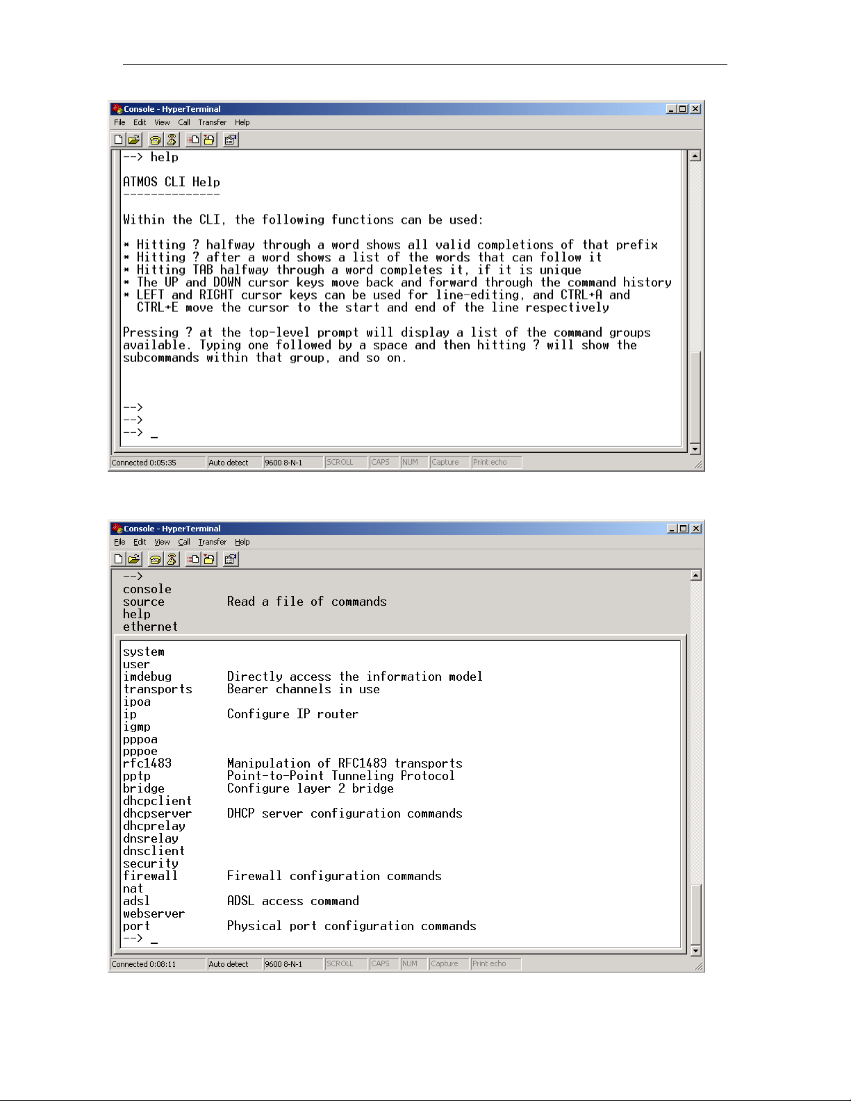
Chapter 7. How to… Solwise SAR715PV ADSL Ethernet Router User’s Guide
This should explain the basic syntax used for command entry. So, if
you press ‘?’ the current commands are listed:
100
This shows the complete list of CLI commands.
 Loading...