

Page 1

ZCS-232
User Guide
Version: 1.0
2013.04.23
Page 2
Revision Date
Document
Version
Pages
Description
Apr. 23. 2013
1.0
All
Initial release
ZCS-232
User Guide
Revision History
Copyright 2013 SystemBase Co., Ltd. All rights reserved.
Website http://www.sysbas.com/
Tel. +82-2-855-0501
Fax. +82-2-855-0580
16F Daerung, Post Tower-1,
212-8, Guro-dong, Seoul, Republic of Korea
If you have any questions, please contact us at www.solvline.com.
2
Page 3

ZCS-232
User Guide
Index
1. Feature .................................................................................................................................................................................... 4
2. Specification ......................................................................................................................................................................... 4
3. Product Contents ............................................................................................................................................................... 5
4. Structure ................................................................................................................................................................................. 5
5. Connector .............................................................................................................................................................................. 6
6. LED ........................................................................................................................................................................................... 6
7. ZCS-232 Network Configuration ................................................................................................................................ 7
A. 1:1 connection between an End Device and a Coordinator .................................................................... 7
B. 1:N connection with one coordinator and several end devices .............................................................. 7
C. Using routers to expand the network ............................................................................................................ 9
8. Configure ZCS-232 ........................................................................................................................................................ 10
A. Setup Mode .............................................................................................................................................................. 10
B. Active Mode ............................................................................................................................................................. 10
C. Add Device ................................................................................................................................................................ 10
D. Delete Device ........................................................................................................................................................... 12
E. Configuration ........................................................................................................................................................... 13
F. Refresh ........................................................................................................................................................................ 14
G. Reboot ......................................................................................................................................................................... 14
3
Page 4
RF Section
Standard
IEEE 802.15.4 ZigBee Pro Standard (250kbps)
Compatible with ZigBee Standard
Modulation
DSSS
Flash Size
256KB
Security
AES
Operating voltage
2 ~ 3.6 V
Antenna
1.5 dB Stub Antenna provided
Serial Section
Interface
RS-232
Signal used
TXD, RXD, CTS, RTS, DTR, DSR
Speed
Max. 250kbps
Hardware & Operating Environment
Operation Voltage
+5 ~ + 9VDC (non-polar)
Adapter
+9V DC, 300mA, ф3.47mm (USB-to-DC Cable provided)
Power Consumption
Max. 0.5W
LED Information
Link, SRL, RDY
Operation Temperature
-40℃ ~ +85℃
Operation Humidity
5 ~ 95%, non-condensing
ZCS-232
User Guide
Preface
Thank you for purchasing product by SystemBase. This product has passed thorough quality control and
during the 5 years warranty period, the customers can receive free repair services from the day the purchase
was made. If you have any questions or difficulties with this product please contact our Technical Support
by submitting an inquiry at http://www.solvline.com.
1. Feature
ZCS-232 is a Serial-to-ZigBee Converter which allows ZigBee (IEEE 802.4.15) communication in Serial
(RS-232) environment with providing coordinator, router, and end device features.
2. Specification
4
Page 5
Contents in ZCS-232 package
ZCS-232
1 unit
Adapter - 9V DC
1 unit
USB Power Cable
1 cable
1.5 dB Antenna (attached to ZCS-232)
1 unit
Warranty Card
1 piece
Brief Catalog
1 book
CD (Manual, Utilities)
1 CD
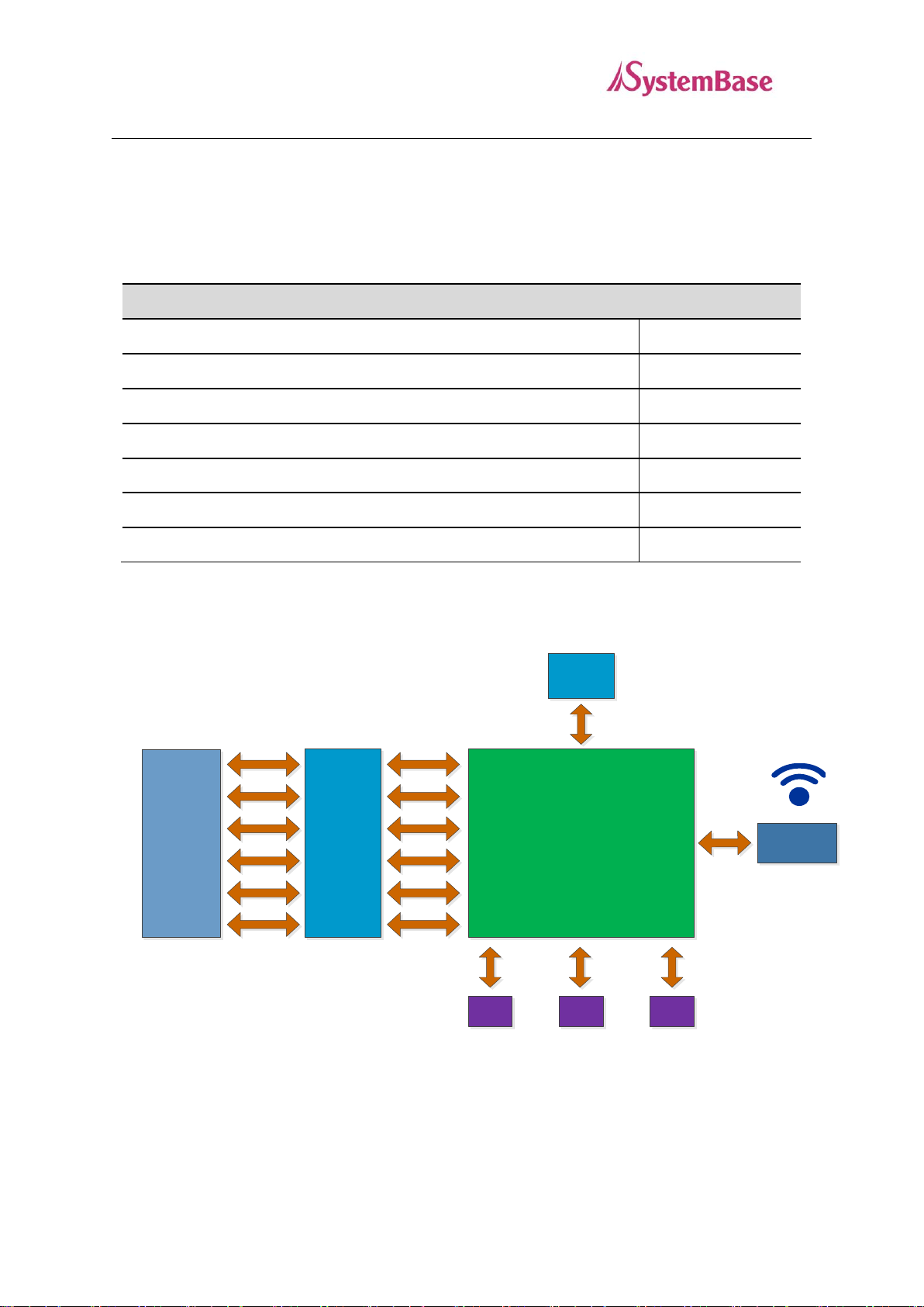
SoC
LDO
SMA/F /RA
LED#1
(RDY)
LED#2
(Link)
LED#3
(SRL)
MAX3242
DB – 9
(Female)
TXD#3
RXD#3
RTS#3
CTS#3
DSR#3
DTR#3
TXD#3
RXD#3
RTS#3
CTS#3
DSR#3
DTR#3
50Ω
Matching
3V3
ZCS-232
User Guide
3. Product Contents
Product contents of ZCS-232 are as follows. Please check if all contents are included.
4. Structure
5
Page 6

ZCS-232
RXD
TXD
DSR
GND
DTR
CTS RTS
1 2
3
4
5
6
7 8 9
LED
Status
Meaning
RDY
(Green)
Blink
Normal operation
Off
System Error
SRL
(Red)
On
Transmitting/Receiving serial data
Link
ON
Network connection complete (For Coordinator, auto
ON)
Blink
Search for device and attempt network connection
ZCS-232
User Guide
5. Connector
6. LED
6
Page 7

Coordinator
End Device
ZCS-232
User Guide
7. ZCS-232 Network Configuration
If necessary, ZCS-232 can be set and used as an end device, a coordinator, or a router.
The ZigBee end device is located at the end of the ZigBee network which can only connect to ZigBee
coordinator or ZigBee router. Existing only one network PAN, the ZigBee coordinator manages each
devices in the network when ZigBee network is first formed. Expansion of the network is done by ZigBee
router. Without ZigBee coordinator, the network cannot be configured.
A. 1:1 connection between an End Device and a Coordinator
To use 1:1 connection with ZCS-232, one of each end device and coordinator is required. Each device can
specify a unique source ID. When the source ID of a device trying to send a data is set to the destination ID,
the data can be transmitted. PAN ID and the channel from the coordinator should be applied to the end
device to form a network.
The below is an example of 1:1 connection using ZCS Configuration Utility.
B. 1:N connection with one coordinator and several end devices
7
Page 8

End Device End Device
Coordinator
End Device
End Device
ZCS-232
User Guide
To use one coordinator with several end devices, all the end devices should be set with the PAN ID and
channel of the coordinator. Additionally, to communicate among end devices, each devices should have a
unique ID as a source ID and the ID from the device trying to send the data should be set in the destination
ID.
Following is an example of 1:N ZCS-232 connection using ZCS Configuration Utility.
8
Page 9

End Device
End Device End Device
Router
Router
Router
Coordinator
End Device
ZCS-232
User Guide
C. Using routers to expand the network
When routers are used, 1:N star type connection by one coordinator can be expanded to a tree type or mesh
ZigBee network structure. This can prevent a bottleneck issue where the data is concentrated to one node
and detour traffic when there is a network connection problem from some paths. If there are any obstacles
between devices, or if the physical distance needs to be extended, you can use numerous ways to resolve
the issue utilizing this connection type. Set the network PAN ID and the channel that you want to expand to
the router to automatically detect the devices and add to the network.
The following is an example of an expanded network set by using ZCS Configuration Utility. This is just
one of many examples where the users can set various ways to build their own network.
9
Page 10

ZCS-232
User Guide
8. Configure ZCS-232
A. Setup Mode
To modify the settings in ZCS-232, mode switch in ZCS-232 should be set to “SETUP” and the power must
be supplied. If you were using ZCS-232, but needed to enter the setup mode, change the mode from
ACTIVE to SETUP. Then unplug the power and replug it to apply the setup mode.
B. Active Mode
After setting configuration for your ZCS-232, set the mode switch from “SETUP” to “ACTIVE”. Then
click on the Reset button from the ZCS Configuration Utility or unplug the power and replug it to apply the
active mode.
C. Add Device
Run ZCSConfig.exe to see the window shown as below. To add a device, click on the “Add Device” button.
10
Page 11

1
2
3
ZCS-232
User Guide
When you click the dropdown box from “Add Device”, COM ports will be displayed, from which you can
add the ports connected to the devices.
If you see a message as shown below, please check for few things.
(1) The connection between the device and the computer.
(2) Select the correct physical port number from the application
(3) Check the mode switch in ZCS-232 whether it is set to SETUP
(4) Unplug and replug the power supply line in ZCS-232.
When the connection between the device and the computer is successful, device information will be
displayed as show below.
11
Page 12

1
2
ZCS-232
User Guide
D. Delete Device
Select the device that you wish to remove and click on the “Delete Device” button to remove the device
from the list.
12
Page 13

1
2
3
4
5
ZCS-232
User Guide
E. Configuration
The above example shows how to modify PAN ID in ZCS-232 connected to COM24 port. The order when
configuring is all the same for other entries, so please refer to this example when you are trying to change
the value for other settings.
As shown in 1 from the image above, select the device from the list which you wish to change the setting
and click on the “Config” button in 2. When “Config” button is clicked, ZCS Configuration window will
appear. Change the values you wish to modify from this window and click OK to finish.
Check if the modified values are applied to the list without any problem. To revert the mode back to active
mode, please follow the few steps shown below.
(1) Set the mode switch in ZCS-232 from SETUP to ACTIVE.
(2) Click the “Reset” button or unplug and replug the power supply line in ZCS-232
13
Page 14

ZCS-232
User Guide
When the mode is successfully changed from setup mode to active mode, any additional operation may
display the message shown above. When it is set to active and configuration is complete, click “Delete
Device” to remove the device from the list. If you need to apply an additional changes, please refer to
changing active mode to setup mode explained previously.
F. Refresh
To refresh the ZCS-232 information in the list or to check whether the device is connected with the setup
mode, click “Refresh” button. When refresh is completed, following message will appear.
G. Reboot
To restart the firmware in ZCS-232, click the “Reset” button. Usually when changing from SETUP mode
to에 ACTIVE mode, this feature is used.
14
 Loading...