

Page 1
User’s Manual
WCS-232 v5.0
User’s Manual
WCS-232 v5.0
User’s Manual
WCS-232 v5.0
User’s Manual
WCS-232 v5.0
SystemBase Co., Ltd. warrants that the product(s) shall be free from
manufacturing defects in materials and workmanship for a period of
five (5) years from the date of delivery provided that the product
was properly installed and used. Defects, malfunctions or failures of
the warranted product caused by damage resulting from acts of God
(such as floods, fire, etc.), environmental and atmospheric disturbances,
other external forces such as powerline disturbances, host computer
malfunction, plugging the board in under power, or incorrect cabling
and damage caused by misuse, abuse and unauthorized alteration or
repair are not warranted.
The warranty is limited to the r
s
option, of the defective product during its warranty period. Customer
must obtain a Return Material Authorization (RMA) number prior to
returning the defective product to SystemBase for service. Customer
agrees to insure the product or assume the risk of loss or damage in
transit, to prepay shipping charges and to use the original shipping
container or equivalent. Contact SystemBase Customer Support at
tech@sysbas.com for further information. Product
warranted for a period of ninety (90) days or the duration of
product warranty period, whichever is longer.
THE PROVISIONS OF THE WARRANTY ARE IN LIEU OF ANY OTHER
WARRANTY, WHETHER EXPRESSED OR IMPLIED, WRITTEN OR
ORAL, AND SYSTEMBASE'S LIABLITY ARISING OUT OF THE
MANUFACTURE, SALE OR SUPPLYING OF THE PRODUCT AND ITS
USE, WHETHER BASED ON WARRANTY, CONTRACT, NEGLIGENCE,
PRODUCT LIABILITY OR OTHER WISE, SHALL NOT EXCEED THE
ORIGINAL COST OF THE PRODUCT. IN NO EVENT SHALL
SYSTEMBASE BE L
DAMAGES, INCLUDING, BUT NOT LTMITED TO, LOSS OF PROFITS
OR USE DAMAGES ARISING OUT OF THE MANUFACTURE, SALE
OR SUPPLYING OF THE PRODUCT.
Help Hotlin
fo
e-mail: tech@sysbas.com
16F Daerung Post Tower-1, 212-8, Guro-dong,
Seoul, Korea / Tel. 82-2-855-0501 / Fax. 82-2-855-0580
www.sysbas.com / www.solvline.com / marketing@sysbas.com
WCS-232 v5.0
RS232 to Bluetooth Converter
User’s Manual
Version 1.0
1. Preface
Thank you for purchasing product by SystemBase. This
product has passed thorough quality control and during
the 5 year warranty period, the customers can get free
repair services from the day the purchase was made. If
you have any questions or difficulties with this product
please contact our Technical Support at http://www.solvline.com.
2. Introduction
● This is a converter which changes RS232 signal to
Bluetooth signal or vice versa.
● The following is the contents in the package.
· WCS-232 v5.0 2EA
· 1dB antenna 2EA
· User manual
· USB power cable 2EA
3. Specification
3.1 Serial Communication
4.2 Hardware
SETUP
SETUP ACTIVE : Setup Mode
4.2 Switch Mode
- LINK: When the power is supplied, red LED starts
- TXD: When a data is transmitted LED is on.
- RXD: When a data is received LED is on.
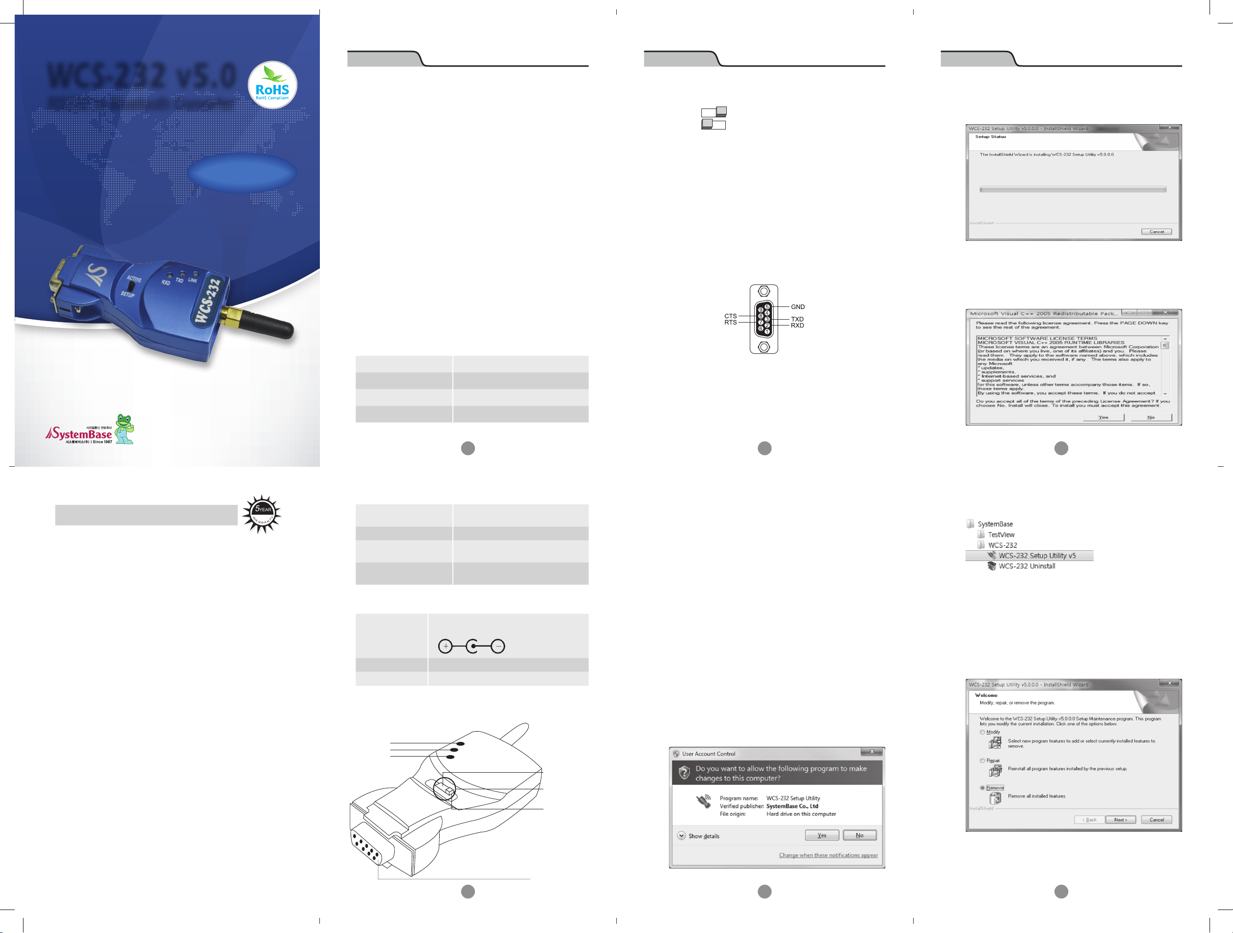
5. Connector
ACTIVE : Active Mode
blinking. When connected with the target
wirelessly, green is on.
(When it is in linked status LED is dimmed.)
RS232 DB9 Female
When the User Account Control window pops up,
click the Yes button.
After installing WCS-232 v5.0 Setup Utility,
Microsoft .NET Framework version 2.0 and Microsoft
Visual C++ 2005 SP1 Redistributable Package will
be ready to be installed.
5-Year Warranty
IABLE FOR UNINTENDED OR CONSEQUENTIAL
e : Technical supports are available to all our customers
r assistance in installation and operation.
[+82-2-855-0501]
epair and/or replacement, at SystemBase'
replaced shall be
YEAR
5
W
A
R
R
A
the initial
Communication Interface RS232
Communication Speed Max. 230.4kbps
Communication Distance Max. 15m
Connector DB9 Female
1
3.2 Bluetooth Communication
Y
T
N
Specification
Frequency
Wireless method
Maximum
Communication Distance
Bluetooth Specification V2.1
+ EDR class 1
2402 ~ 2480 MHz
Frequency Hopping Spread
Spectrum
100m
3.3 Hardware
5V from USB port on the PC
Power Supply
Dimension 36.8(W) x 19.0(D) x 74.2(H)
Weight 35g
Can be used with 5~12V DC adapter
6. Installation
6.1 Connect
Connect WCS-232 to a serial port on a PC or a
communication device and supply power.
3
WCS-232 can get the power from USB cable
connected to the USB port on the PC.
When both WCS-232 is powered up, they will be
connected using Bluetooth. This is when you can
start using the serial port.
6.2 Environment Setting
Since WCS-232 is connected to the serial port,
serial related settings (baud rate, data bit, parity
bit, stop bit, and flow control) and RF related
configurations (name of the device, operation mode,
target address) are required to be set. Regarding
RF connection settings, if WCS-232 is not trying to
connect to other WCS-232 but Bluetooth device from
other companies or when trying to reset the settings
to the factory default, it is required.
5
Proceed with Microsoft Visual C++ 2005 SP1
Redistributable Package installation.
After WCS-232 Setup Utility installation is complete,
click WCS-232 v5.0 Setup Utility v5 from the Start
button → SystemBase → WCS-232.
6.4 Remove WCS-232 Setup Utility
Click WCS-232 Uninstall from Start button →
SystemBase → WCS-232
6.3 WCS-232 Setup Utility Installation
4. Structure
4.1 External Form
LINK
TXD
RXD
Antenna
ACTIVE MODE
Mode Switch
SETUP MODE
Run WCS-232 Setup Utility. You can download
the file from our homepage or find it from the CD
included in the product package.
Proceed with uninstallation by clicking on the
Remove selection.
RS-232 Side (DB9)
Female Connector
2
4
6
Page 2
User’s Manual
WCS-232 v5.0
User’s Manual
WCS-232 v5.0
User’s Manual
WCS-232 v5.0
User’s Manual
WCS-232 v5.0
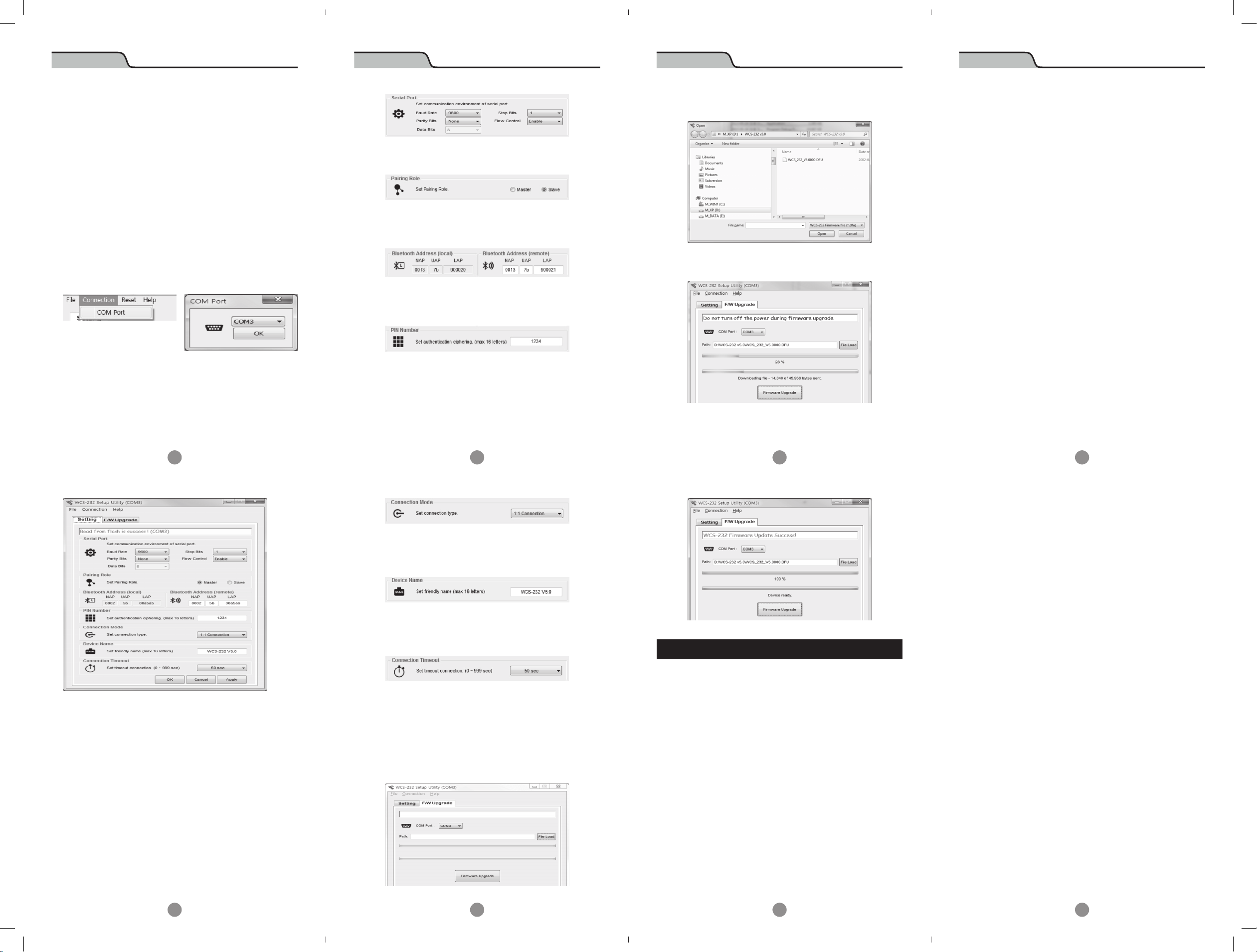
7. Operation Environment Configuration
7.1 How to configure
Dedicated WCS-232 v5.0 configuration utility can
be used to modify communication speed, parity,
stop bit, device name, and operation mode.
■ Retrieve settings
① Connect WCS-232 to COM port and supply power to
the unit.
② Set switch in WCS-232 to Setup Mode.
③ Run WCS-232 v5.0 Setup Utility
④ From the utility, click Connection then COM Port at
the top of the menu to select the port to connect.
⑤ When successfully completed, “Read from flash is
success” message will appear.
■ Pairing Role
Select Master/Slave mode
■ Bluetooth Address
Current Bluetooth address can be checked. The target
Bluetooth address can be checked and set.
■ Pin Number
When connecting to the Bluetooth device, this pin is required.
Up to ASCII 16 characters can be set for a pin number.
■ Connection Mode
WCS-232 v5.0 supports “1:1 connection” a n d “connection
waiting” modes.
In 1:1 connection mode, connection is established when
the add re s s of the Bluetoot h devic e is ent ered manua l ly.
In connection waiting mode, When a target device is
not specified, it will look for new devices automatically.
3. When the “File Load” button is clicked, following
dialog box will appear.
4. When you click on the “Firmware Upgrade” button, it will
upload the firmware and show the progress from the bar.
5. After uploading the firmware is completed, the
following message will appear.
1-2 Check the pin wiring
• Data transmit/receiving devices are separated to
DTE (Data Terminal Equipment) device and DCE
(Data Communication Equipment) device. Generally, a
terminal such as a PC is a DTE device and a data relay
system such as a modem is a DCE device. According
to RS-232 standard, when DTE device is required to
connect to a DCE device, two devices are connected
directly or by 1:1 cable.
In other words, signal lines such as TX and RX or
signal control line should not be crossed but connected
directly. However, when two same kind of devices,
such as DTE and DTE, or DCE and DCE devices needs
to be connected, cross cable (often called the null
modem cable) is used. This cable is used to connect
TX with RX signal lines and cross connect other
signal control lines.
WCS-232 v5.0 is a DCE device required to be connected
to a PC directly. Therefore, if it needs to be connected
to a DTE device, it can be connected to a DTE device
directly or use a 1:1 cable. However, if it needs to be
connected to a DCE device or a modem, a cross cable
is required to be used.
2. Data loss or dysfunction
2-1 Hardware control
• WCS-232 v5.0 sends a data received from the host to the
7
■ Save settings
① Click Apply button to save the settings in the device
memory.
② After it is saved, “Write to flash is success” message
will appear.
③ Click on the OK button to save the settings in the
device memory and close the windows.
7.2 Operation Setting
■ Serial Port
Set ser ial commu n icat ion config uration for SPP (Ser ia l Port
Profi le).
9
■ Device Name
A device name can be given here with up to 16 ASCII
characters.
■ Connection Timeout
Set a given period of time until the Bluetooth device
searches and connects.
8. Firmware Upload
1. WCS-232 v5.0 unit and the DFU (Device Firmware
Upgrade) file is required to upload a firmware.
2. Select F/W upgrade tab.
11
Appendix : Troubleshooting
1. Things to check when communication is not established.
1-1 COM port setting
• WCS-232 v5.0 supports 8 data bits only. When the
host supports 7 data bits and even or odd parity,
WCS-232 v5.0 can be set to 8 data bits, no parity
(factory default state). However, it cannot be applied
to a device such as 7 bit USB dongle.
• Check whether both WCS-232 devices are set to the
same parity and stop bit. WCS-232 supports v5.0 no,
even and odd parity and 1 or 2 stop bits.
• RTS (Request To Send) and CTS (Clear To Send) signal
from RS-232 standard are used for data transmit/
receiving (Hardware Flow Control or Hardware
Handshaking) control purpose.
• WCS-232 v5.0 does not support the break signal from
RS-232, thus it cannot be used for the device which
requires such feature.
13
target Bluetooth device, but when the communication
environment is not good, resending packets will be
repeated resulting a delay in communication. When
a hardware flow control is not used, internal buffer
in WCS-232 v5.0 may receive more data than it can
handle, causing an overflow. Therefore when the
wireless environment is not good, it is recommended
to use the hardware flow control.
3. Delay in communication
3-1 Delay in converting to wireless signal
• When WCS-232 v5.0 converts a data from the
host to wireless signal, it takes about 30 msec.
This delay may be increased due to the wireless
connection environment. Additionally, when WCS232 v5.0 receives a data it converts to the wireless
signal immediately. Therefore, sequencing data can
be divided and transmitted. To prevent this, InterCharacter Timeout feature is provided which is when
no data is received from the serial port, transmission
begins.
3-2 Wireless Environment
• The Bluetooth uses 79 channels to transmit a data
to avoid interferences. However, when there are
numbers of Bluetooth devices in a small area, trying
to send a large amount of data, data loss or error
may occur. WCS-232 v5.0 can use 1.2 AFH feature in
Bluetooth to avoid Wi-Fi interference, but depending
on the distance or the number of the devices, it may
have less effect in such environment.
8
10
12
14
 Loading...