

Page 1

SerialGate
SG-3011PCL
Manual
Version: 1.0
2013.12.05
Page 2
2
Modified on
Document Version
Modified Pages
Description
Dec. 05 2013
1.0
All
New
SerialGate User Manual
History
Copyright © 2013 SystemBase Co., Ltd. All rights reserved.
Website http://www.sysbas.com/
Technical Support http://www.solvline.com/
Phone +82-2-855-0501
Fax +82-2-855-0580
16F Daerung Post Tower-1, 212-8, Guro-dong, Guro-gu,
Seoul, Republic of Korea
For any inquiries, please visit our technical support website.
Page 3
3
SerialGate User Manual
Index
Chapter 1. Overview 5
About this manual 5
To readers 5
Organization of the manual 6
SG-3011PCL related documents 7
Technical Support 8
Chapter 2. Getting Started 9
Overview 9
Function 9
Chapter 3. Hardware 10
Product Images 10
LEDs 11
Reset Switch 11
Chapter 4. Setup 15
Before connecting to the network 15
Running the SG-3011PCL for the First Time 15
Network Access 15
Chapter 5. Configure by Web Browser 17
Connecting with Web Browser 17
Page 4

4
SerialGate User Manual
Network Setting 18
Serial Setting 20
GPIO Setting 23
Change ID/Password 24
Reboot 24
Chapter 6. Applied Examples 25
Com Port Redirector Mode 25
TCP_Server Mode (Connect from PC to SerialGate using TCP/IP) 27
TCP_Client Mode (Connect from SerialGate to PC using TCP/IP) 28
Chapter 7. Appendix 29
Troubleshoot 29
GPIO Configuration 31
Upgrade 35
Product Specification 38
Ordering Information 40
Page 5

5
SerialGate User Manual
Chapter 1. Overview
This chapter covers related documents for the SG-3011PCL.
About this manual
This manual describes how to connect and configure settings for the SG-3011PCL.
To readers
This manual is written for SG-3011PCL users and administrators. It is recommended to read
this manual thoroughly before using SG-3011PCL. This will provide users more understanding
when connecting SG-3011PCL with other devices.
Page 6

6
SerialGate User Manual
Organization of the manual
Chapter 1. General information and introduction.
Chapter 2. Features of SG-3011PCL
Chapter 3. Hardware Configuration, product images and specification.
Chapter 4. How to setup the device in the network and configuring and checking the status for
the first time use.
Chapter 5. Menus in the web managers and their usage.
Chapter 6. Examples of various applied fields and the correct usage.
Chapter 7. Detailed specifications for the product and ordering information.
Page 7

7
Documents
Description
SG-3011PCLSpecification Sheet
Specification of SG-3011PCL
SG-3011PCLWhite Paper
An overview of a SerialGate device server.
Documents
Description
User Manual
SG-3011PCL configuration, management, and usage
COM Port Redirector
User Manual
COM Port Redirector usage and description
TestView User Manual
COM Port/TCP/UDP test program usage and description
SGconfig Quick Manual
SerialGate device configuration utility usage and description
SerialGate User Manual
SG-3011PCL related documents
To get more information about SG-3011PCL, please visit http://www.solvline.com/. The most
recent SerialGate related documents, drivers, utilities and firmware will be available for
download as well as FAQs to troubleshoot problems. Additionally, any inquiries or comments
can be posted.
All documents in the technical support website is up to date. The contents of the documents
may be modified and updated without prior notice.
Page 8
8
SerialGate User Manual
Technical Support
There are three ways to receive technical support from SystemBase.
The customers can also leave feedback about the products.
1. Visit our technical support website at http://www.solvline.com/.
2. Contact us by email at tech@sysbas.com.
3. The customers can reach us directly by phone during our office hours.
Phone: +82-2-855-0501
Office hours: Monday to Friday, 09:00 ~ 18:00 KST (Closed on national holidays in South
Korea)
Page 9

9
SerialGate User Manual
Chapter 2. Getting Started
This chapter describes the features of the SG-3011PCL.
Overview
The SG-3011PCL can connect to various types of device to the network whether it is a security
equipment, communication peripheral, modem, data output device, industrial test or measuring
equipment. The SG-3011PCL supports RS-232/422/485 or UART standard serial
communication and provides programmable GPIOs along with 10/100 based TX fast Ethernet
port to connect to the network.
Function
Basic Function
- Max. 230.4Kbps (for RS-232/422/485/UART TTL)
- RS-232 (Full Signal)
- RS-422/485
- Supports UART TTL
- Flow Control (RTS/CTS, DTR. DSR, Xon/Xoff)
- 6 Programmable GPIOs
- 1 x 10/100 Mbps(Auto MDIX) Ethernet port
- Supports COM Port Redirector
- Configure with web browser
Package Content
The package only comes with one unit of SG-3011PCL.
Page 10
10
SerialGate User Manual
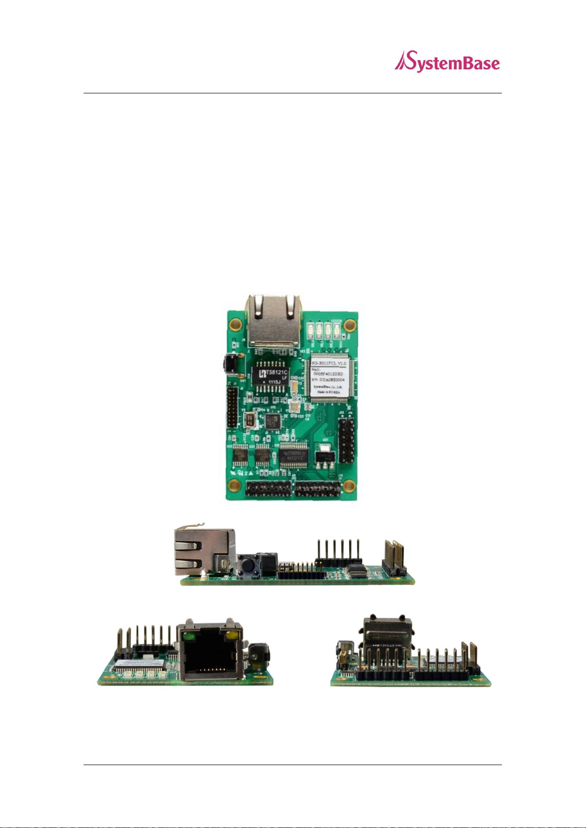
Chapter 3. Hardware
In this chapter, the users can find the information regarding the pin specification, port, pin
headers, LEDs and the reset button.
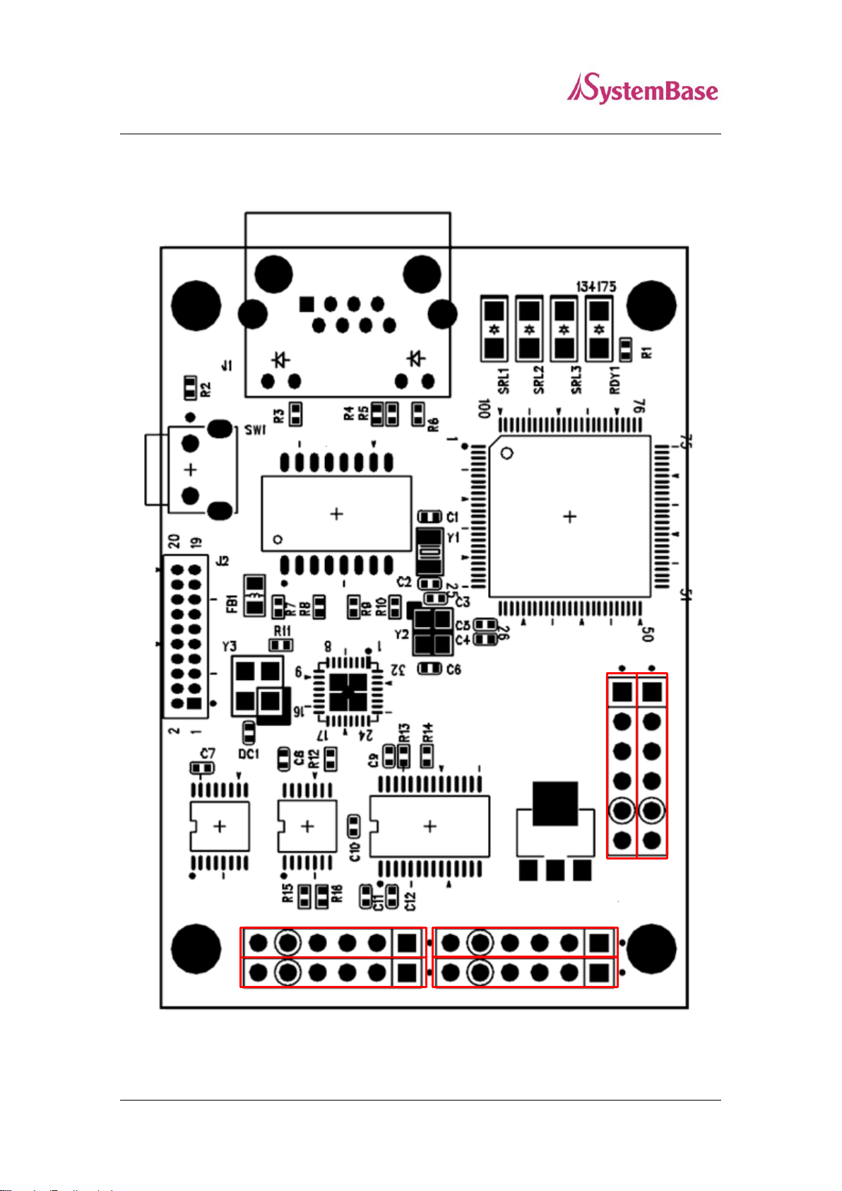
Product Images
Page 11
11
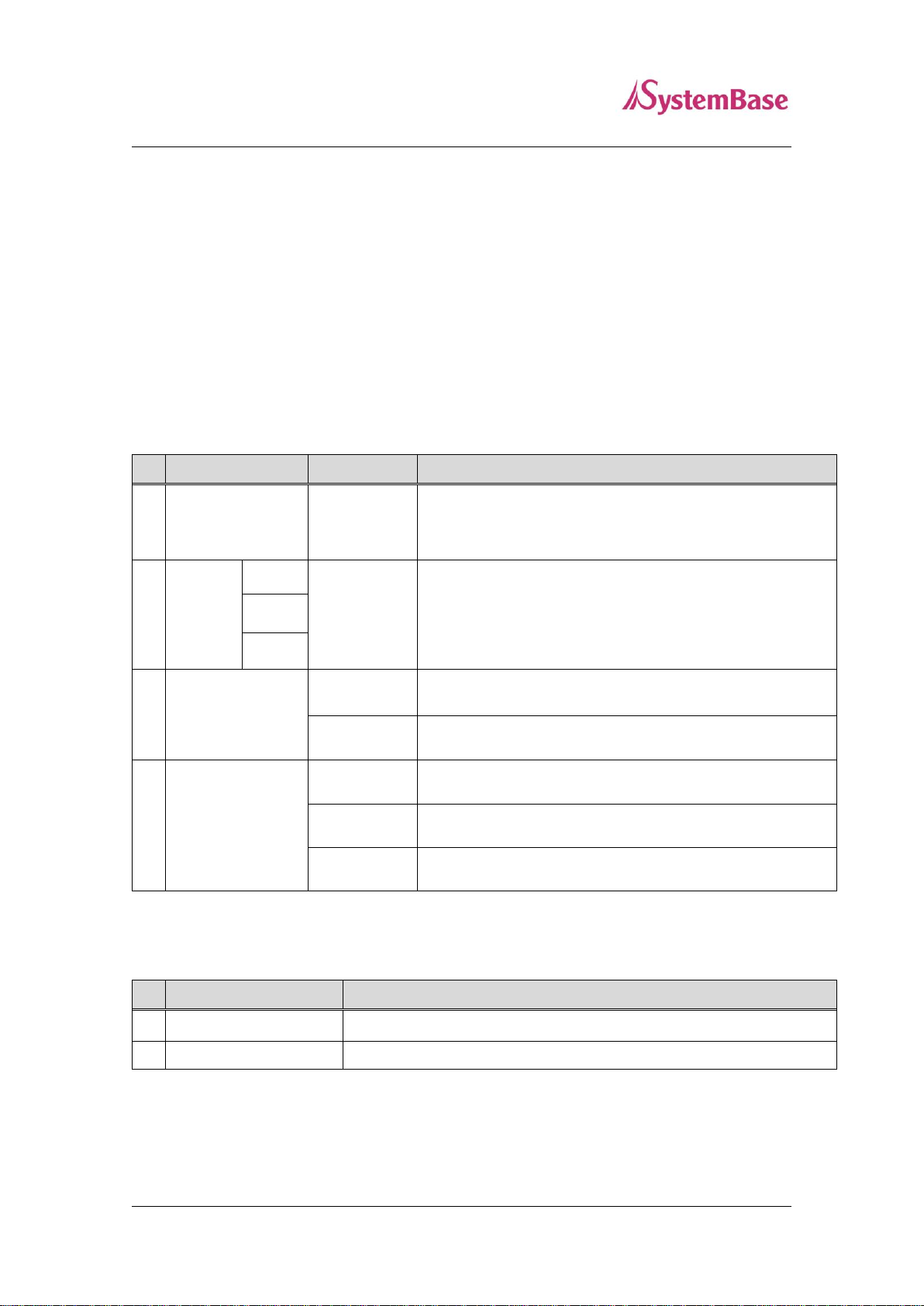
LED Name
State
Operation
1
RDY
Blink
When the device is powered, it will stay on for a while then
start blinking when booting process is completed.
2
SRL
(Red)
1
Blink
Transmitting/Receiving data
1. RS-422/485
2. RS-232
3. TTL
2
3
3
LAN Port
(Green on Left)
On
100 Base Tx Standard network enabled
Off
10 Base Tx Standard network enabled
4
LAN Port
(Yellow on Right)
On
Connected to the network
Off
Network disconnected
Blink
Transmitting/Receiving LAN data
Pressed for
Description
1
Less than 3 seconds
Restarts the SG-3011PCL
2
3 seconds or more
Reverts all settings to the factory default values.
SerialGate User Manual
Serial/Power/GPIO Connector: 2.54mm pin header
Reset Button: Restarts SG-3011PCL or load the factory default depending on the time it is
pressed. (More information in the can be found below.)
LED: Shows the status of the SG-3011PCL.
(More information can be found below.)
LAN (Ethernet) Port: This port, 8-pin RJ-45, is used to connect the SG-3011PCL with the
LAN/Ethernet port in the PC, hub, router, or other wired network device.
LEDs
Reset Switch
Page 12
12
1
6
6
1
1
6
J6
J8
J5
J7
J3
J4
SerialGate User Manual
Pin out
Page 13

13
Name
Function
Level
1
VCC
DC 5V Power Supply
5VDC ±5%
2
RXD
Receive Data
RS-232
3
TXD
Transmit Data
RS-232
4
GND
Ground
- 5 RTS
Request to Send
RS-232
6
CTS
Clear to Send
RS-232
Name
Function
Level
1
VCC
DC 5V Power Supply
5VDC ±5%
2
DTR
Data Terminal Ready
RS-232
3
DSR
Data Set Ready
RS-232
4
GND
Ground
- 5 DCD
Data Carrier Detect
RS-232
6
RI
Ring Indicator
RS-232
SerialGate User Manual
The SG-3011PCL supports RS-232/422/485 speeds from 300bps to 230.4Kbps. For RS-232, it
supports the full signal (TxD, RxD, RTS, CTS, DSR, DTR, DCD, RI). The 4 wires are supported
for RS-422/485 and 2 wires for RS-485 only.
The users can use the UART TTL in the SG-3011PCL. It provides six programmable GPIOs to
control external devices, for monitoring or communicating purposes. The only on port of UART
TTL or RS-232/422/485 can be used.
①. RS-232
For RS-232, J6 and J8 are used. The pin out information is show below.
J8
J6
Page 14

14
Name
Function
Level
1
VCC
DC 5V Power Supply
5VDC ±5%
2
TX+/TRXD+
RS-422: Transmit Data +
RS-422
RS-485: Data +
RS-485
3
TX-/TRXD-
RS-422: Transmit Data -
RS-422
RS-485: Data -
RS-485
4
GND
Ground
- 5 RX+
RS-422: Receive Data +
RS-422
6
RX-
RS-422: Receive Data 1
RS-422
Name
Function
Level
1
VCC
DC 5V Power Supply
5VDC ±5%
2
RXD
Receive Data
3.3V TTL
3
TXD
Transmit Data
3.3V TTL
4
GND
Ground
- 5 RTS
Request to Send
3.3V TTL
6
CTS
Clear to Send
3.3V TTL
Name
Function
Level
1
PB5
GPIO
VIL: Vss - 0.3V (Min.)
VIH: 2.0 ~ VCC+0.3V
VOL: Max.0.4V
VOH: Min.2.4V
2
PB6
GPIO
3
PB7
GPIO
4
PB8
GPIO
5
PB9
GPIO
PB14
GPIO
SerialGate User Manual
②. RS-422/485
For RS-422/485, J5 and J7 are used. The pin out information is show below.
J5, J7
③. UART TTL
SG-3011PCL provides UART TTL pins. The pin out information is show below.
J4
④. GPIO
SG-3011PCL provides GPIO pins. The pin out information is show below.
J3
Page 15

15
SerialGate User Manual
Chapter 4. Setup
This chapter deals with connecting SG-3011PCL with other devise using the Ethernet and RS-
232/422/485 connection.
Before connecting to the network
The SG-3011PCL supports 10/100Mbps LAN/Ethernet and auto MDIX feature so that the users can
use either cross or direct cable.
Running the SG-3011PCL for the First Time
First, check the input voltage to the SG-3011PCL. It is recommended to use 5 VDC. The device can
handle up to 9 VDC. When the device boots, its RDY LED will stay on then starts blinking when
booting process is completed.
After the LEDs from the LAN port are blinking, the users can connect to the SG-3011PCL using any
web browser.
Network Access
In order to enter the web manager, the users require the default IP address to connect to the SG-
3011PCL which is 192.168.0.223. This initial static IP address can be changed from the web manager
to be a different static IP or a dynamic IP. It is recommended to use a static IP.
When the IP addressing of the SG-3011PCL is set to the dynamic IP or the users forgot the static IP to
connect to the web manager, the SGConfig utility can be used to retrieve the IP address of the SG-
3011PCL as shown in the next page.
Page 16

16
SerialGate User Manual
If the SG-3011PCL cannot be found with the “Search” button or uses the different group of IP address,
try the instructions below to connect.
Default IP Address: 192.168.0.223
The IP address of the SG-3011PCL is set to 192.168.0.223 by default. Before the SerialGate is
installed in the place where it would operate, the users should first configure the settings that suits its
operating environment. However, if the PC have a different IP group, it may not be able to connect to
the SerialGate even if the users entered the default IP address. In this case, please establish a connect
to the SerialGate with the PC directly using the Ethernet cable and set the IP address of the PC to the
same group that the SerialGate is set to. It is recommended to set the IP address of the PC as shown
below when directly connected to the SerialGate.
Page 17

17
SerialGate User Manual
Chapter 5. Configure by Web Browser
This chapter will go over with configuring the SG-3011PCL using the web manager.
Setting with the SGConfig utility will be dealt from a separate quick manual.
Connecting with Web Browser
Open a web browser and type the IP address of the SG-3011PCL. A login window, shown below, will
appear. The initial ID and password are “serialgate” and “99999999” without quotes. The ID and
password can be modified once logged in.
Page 18

18
Menu
Default
Description
Device Name
SerialGate
Displays the device name
MAC Address
(different among
each devices)
Displays the MAC address
(cannot be modified)
Connection
Type
Static IP
Can be selected between DHCP (Dynamic IP) or Static IP
IP Address
192.168.0.223
The IP address of the current device.
(If the ‘Connection Type’ is set to ‘Static IP’, enter the
value manually, but if it is set to ‘DHCP’ IP address cannot
be changed manually.)
SerialGate User Manual
Network Setting
After logged in, the ‘Network Setting’ page will be displayed. Every values in here except the MAC
address can be modified. The page is shown as below.
The ‘Network Setting’ display the operating environment for currently connected network. The ‘Submit’
button must be clicked in order to save the changes. To apply changed settings, the device must be
rebooted. If the submit button is not clicked to save the changed settings, when the device boot next
time, the changed value will not be applied.
The ‘Cancel’ button can be used to revert the settings back to the original state.
Information displayed in the ‘Network Setting’ page is show below.
Page 19

19
Subnet Mask
255.255.255.0
Configure current subnet mask.
(If the ‘Connection Type’ is ‘Static IP’, enter the subnet
mask manually. The dynamic IP does not require
masking, thus, the value cannot be entered.)
Gateway
192.168.0.254
Configure current gateway address.
(If the ‘Connection Type’ is ‘Static IP’, enter the gateway
address manually. Dynamic IP does not require masking,
thus, the value cannot be entered.)
DNS
168.126.63.1
Enter the address of the authoritative name server for
DNS (Domain Name Service).
SerialGate User Manual
Page 20

20
Menu
Default
Description
Operation
Mode
COM
Redirector
Select the operation protocol that will be applied in the serial port.
COM Redirector
Use the serial port of SerialGate as a virtual COM port in Windows
2000/XP/2003/Vista.
SerialGate User Manual
Serial Setting
The ‘Serial Setting’ display the operating environment for the RS-232/422/485 port. The ‘Submit’ button
must be clicked in order to save the changes. To apply changed settings, the device must be rebooted.
If the submit button is not clicked to save the changed settings, when the device boot next time, the
changed value will not be applied.
The ‘Cancel’ button can be used to revert the settings back to the original state.
Information displayed in the ‘Serial Setting’ pages are show below.
Page 21

21
Menu
Default
Description
TCP Server
SerialGate works as a socket server, waiting for the client
connection on the network. Socket number for awaiting connections
can be set in ‘Local Port’ field. After socket connection, data
between socket and serial port will be transmitted.
TCP Client
SerialGate acts as a socket client in this mode. It tries to connect to
the server IP address and the socket number assigned when a
certain server waits for connection on the network.
All data between the socket and the serial port is transferred
untouched after the socket connection is established.
UDP Server
SerialGate works as a UDP server, waiting for UDP connection from
the client on the network.
Socket number for awaiting connections can be set in ‘Local Port’
field.
Once a UDP packet is received to the socket that waits for the
connection, the data is transmitted to the serial port. The data input
from the serial port is put into UDP packets, which eventually are
sent to the client.
UDP Client
When the data is input to the serial port, UDP packets are sent
using the preset IP address and the socket number of the server.
Interface
RS-232
RS-422
RS-485
Select the serial port interface.
Local Port
4001
Set the socket number for the port. TCP server and UDP server
operation mode makes use of this port for awaiting network socket
connections.
Target IP
192.168.0.224
Set the IP address of the target device used for TCP Client, UDP
Client mode.
Target
Port
4001
Set the port number of the target device used for TCP Client, UDP
Client mode.
SerialGate User Manual
Page 22

22
Menu
Default
Description
Latency
Time
0
This needs to be set when consecutive data from the given serial
port needs to be transmitted to socket at once.
For example, if 100 bytes of character string are to be transmitted
from the serial device to a server through SerialGate, bypass is set
to 0 for the latency time. Although it provides immediate sending
through SerialGate, the server could be received a lot parts of
divided packets.
If the latency time is not 0, SerialGate will wait for the time and
check new data. If there is new data, SerialGate repeatedly wait for
the time. Otherwise, SerialGate will transfer the buffered data, but it
could not run in real time.
(Range: 0 ~ 999)
Baud
Rate
9600 bps
Set the communication speed.
(Options: 150, 300, 600, 1200, 2400, 4800, 9600, 19200, 38400,
57600, 115200, 230400 bps)
Data Bits
8
Data bits are set to 8 and cannot be changed.
Stop Bits
1
Set the stop bit (Options: 1, 2)
Parity
No
Set the parity bit. (Options: No, Odd, Even)
Flow
Control
None
Enable hardware controlled flow control of the data
(Option: None, RTS/CTS)
SerialGate User Manual
Page 23

23
Menu
Default
Description
Direction
In
Set the direction of the GPIO.
In: Set GPIO pin to receive only mode.
Out: Set GPIO pin to send only mode.
Value
Low
Set the output value from the pin.
Low (0): Set the output value to low (zero).
High (1): Set the output value to high (one).
Pull Up
/
Pull Down
No
Enable using the terminating resistor.
No: Disable use of the terminating resistor.
Pull Up: Enable the pull up resistor.
Pull Down: Enable the pull down resistor.
TCP Port
5000
By using TCP Client mode from other devices, the users can
connect to SG-3011PCL and modify the configuration values or test
the device. The port number to connect to this device is specified
here.
For more information about the commands, to modify the
configuration values or testing the device, please refer to chapter 7.
SerialGate User Manual
GPIO Setting
From GPIO menu, GPIO related settings can be modified.
Information displayed in the ‘GPIO’ page is show below.
Page 24

24
SerialGate User Manual
Change ID/Password
Current ID and password can be changed.
Reboot
The unit will restart. If any values are changed, click the submit button before rebooting.
Page 25

25
SerialGate User Manual
Chapter 6. Applied Examples
This chapter covers different modes commonly used in the SerialGate.
Com Port Redirector Mode
The users can use the COM port after registering the COM port in SerialGate as if it is attached directly
in the PC.
Install the COM port Redirector and configure the settings as following. The COM Port Redirector can
be installed from the included CD. Please refer to the manual for installing the COM Port Redirector.
In the example below, the IP address of the SerialGate is set to 192.168.0.223. It is using COM port
number 1. The users can use the COM1 from the PC to access the COM port in the SerialGate.
Page 26

26
SerialGate User Manual
To use the COM port redirector installed in the PC with the SerialGate, set the operation mode to
‘COM Redirector’ as shown below. The local port can be different than the one shown below.
Page 27

27
SerialGate User Manual
TCP_Server Mode (Connect from PC to SerialGate using TCP/IP)
From the client program in the PC, connect the first serial port of the SerialGate.
Try to connect to the SerialGate using the IP address and local port number, 4001, when connecting
from a PC. As shown below, change the operation mode to ‘TCP Server’ and check the local port
number.
Check the communication speed of a serial device to be connected to the serial port, and set the
settings at the ‘Serial Options’ from the web manager.
Page 28

28
SerialGate User Manual
TCP_Client Mode (Connect from SerialGate to PC using TCP/IP)
Connects SerialGate to the client program in the PC using TCP/IP methods.
Since the connection is done from the SerialGate to a PC, change the operation mode to TCP Client
and register IP address and local port number of the PC that you want to connect.
Check the communication speed of the serial device connected to the serial port in the SerialGate, and
set it in the “Serial Options”.
Page 29

29
SerialGate User Manual
Chapter 7. Appendix
Troubleshoot
In this chapter, the users can solve problems they encounter while using SG-3011PCL.
Installation problem
If the users cannot connect to the device using SG-3011PCL, check the network connection
and the cable.
Check if all network cable and the RS-232/422/485 cable is connected correctly.
Check if the IP address and the port number are correct.
If the LAN port LEDs are not on or blinking as they are supposed to according to the page 11
of this manual, there may be a problem with the Ethernet cable or the port from the hub.
Replace the Ethernet cable with different one. If there is a hub in the network, try connecting
to different port in the hub or switch to a different hub.
Network Settings problem
When using TCP/IP connection type, check if the PC has same the IP address group as the
SG-3011PCL. (Use the ‘ping’ command from the PC to check if it can reach the SG-3011PCL.
Please refer to Microsoft help page regarding the ‘ping’ command.) The IP address of the SG-
3011PCL must be in the same logical network as the PC. For example, the IP address of the
PC is 192.189.207.3 and the sub network is 255.255.255.0. Then the IP address of the
SerialGate needs to be 192.189.207.N (where N is from 1 to 254.
When SG-3011PCL is set to get the IP address from the DHCP server, the IP address may
change. To avoid the problem caused from this issue, set the DHCP server to permanently
issue an IP to the SG-3011PCL or set the SG-3011PCL to have a static IP address from the
web manager.
Page 30

30
SerialGate User Manual
When there are IP conflict issue in the network, check if the IP address is correct in SG-
3011PCL. Other device may use a same IP address.
Check if the PC and the SG-3011PCL are using the same subnet. (For example, if the subnet
is set to 255.255.255.0 in SG-3011PCL, the PC should have the same value.)
If the wrong IP address is issued to the SG-3011PCL from the DHCP server, check the server
side.
Windows (OS) problem
If the Windows cannot establish connection to the SerialGate, the serial device cannot be
connected either. Check if the Windows can send ping to the SerialGate using the ‘ping’
command. (For example, “ping N.N.N.N” where N.N.N.N is the IP address of the SG-
3011PCL).
If there are any problem with the COM port Redirector installed in the PC, check if the
virtual port is correctly used. The application should use the same port number as the one
assigned by the Redirector.
Page 31

31
PB5 PB6
PB7 PB8
PB9 PB14
Input
Output
SerialGate User Manual
GPIO Configuration
This section covers an example of how to connect SG-3011PCL using TCP client mode and
setting GPIOs then read/write from them.
Assume that the users are using the GPIO pin as shown below. The PB5, PB7, and PB9 can be
used to retrieve the output value from PB6, PB8, and PB14.
Install the TestView and run it. Select ‘Port’ from the menu, then click ‘TCP/UDP Port’.
Page 32

32
SerialGate User Manual
Select ‘TCP Client’ under connection type and enter the IP address and the port number for the
SG-3011PCL as shown below. Since SG-3011PCL only have one port, select ‘1Ports’. (This,
‘1Ports’, is a known typographical error which will be corrected later.)
Click the ‘Terminal’ button first, and click ‘Windows’ then ‘Tile’.
The users can enter the commands and get the values returned with the terminal window.
When using the commands to set the value and read from it, pin numbers are used. Each pin
names corresponding to the pin numbers are as follows.
Page 33

33
Pin Number
0 1 2 3 4
5
Pin Name
PB5
PB6
PB7
PB8
PB9
PB14
SerialGate User Manual
As shown above, let us assume that PB5 and PB6 are connected to each other. The value from
PB6 can be read from PB5 using the command below.
Since the output values of PB6, PB8, and PB14 are connected to PB5, PB7, and PB9
individually as shown in the figure from page 30, when the commands are entered from the
terminal, low from PB6, high from PB8, and low from PB14 are shown as below.
(When using TestView to enter the command, it will be show in the terminal screen, but the
returned value will be displayed as shown below.)
As shown above, the high value is shown with the value 1 and 0 for the low.
The next example is setting output for pin 1(PB6).
Page 34

34
SerialGate User Manual
If the it need to be set as low for pin 1, use the ’10.’. Command. If the above command is
successfully processed, ‘O’ will be displayed to show OK. If the command returns an error, ‘E’
will be displayed.
Now that PB6 pin 1 value is set to ‘high’, PB5 pin 0 can output its value which is 1. When ‘0-’
command is entered, the following value will be displayed.
If the command syntax is in wrong format, or the value is not correct, an ‘E’ will be displayed
which stands for ‘error’.
Page 35

35
SerialGate User Manual
Upgrade
By using SGConfig utility, the users can update the firmware in the SG-3011PCL.
Please follow the instruction below to update the firmware.
1. Run SGConfig_v1.0.exe
2. Click the ‘Search’ button and select the device you wish to update the firmware. Then, click
the ‘Upgrade Firmware’ button.
Page 36

36
SerialGate User Manual
3. Browse through the directory and select the firmware file.
4. After clicking the ‘Open’ button, a progress bar will appear as shown below.
5. When updating process is complete, the following window will display.
Page 37

37
SerialGate User Manual
6. Press and hold the reset switch from the device for less than 3 seconds to restart the device.
7. Use the SGConfig utility and use the ‘Search’ button to check the information of the device.
The firmware version will be displayed under the ‘Version’ column.
Page 38

38
Ethernet Port
1 port: 10/100Mbps RJ-45
Acquiring Network
Address
Static IP, DHCP (Dynamic IP)
Connector
Pitch 2.54mm Pin Header
Serial Interface
RS-232/422/485, UART TTL
Speed
Max 230.4kbps
Signals
RS-232 : TxD, RxD, DTR, DSR, CTS, RTS, DCD, RI
RS-422 : TX+, TX-, RX+, RX-
RS-485 : TRXD+, TRXD-
UART TTL : TxD, RxD, RTS, CTS
Power Supply
5 VDC Adapter
Power Consumption 1.2 W
ESD Protection
± 15kV ESD (HBM) Protection
LED
Ready, Serial Communication Traffic Indicator
RJ-45 Connector: Speed (Green), Link/Activity (Yellow)
Dimension
46(W) x 68(L) x 15(H) mm
Weight
20.7g
Operating
Temperature
0 ~ 70℃ / -40 ~ 85℃ (depends on models)
Humidity
5 ~ 95% Non-Condensing
SerialGate User Manual
Product Specification
Communication ( Ethernet )
Communication ( Serial )
Hardware ( Electrical )
Hardware ( Physical )
Page 39

39
Pressed for
Action
Result
Less than 3 seconds
Press and hold
then release
after required
time period
Restarts the SerialGate
3 seconds or more
Reverts all settings to the factory default
values.
Protocol
TCP, UDP, ICMP, DHCP, HTTP
Utility
PortView
Configuration by
Web browser, SGConfig
SerialGate User Manual
Reset Button
Software
Page 40

40
Model Name
Description
SG-1010/232-RJ
1 x Serial RJ-45 Port (RS232 only)
SG-1010/Combo-RJ
1 x Serial RJ-45 Port (RS422/RS485 selectable)
SG-1010/ALL
1 x Serial DE-9 or T/B Port (RS232/RS422/RS485 selectable)
SG-1010W/ALL
1 x Serial DE-9 or T/B Port (RS232/RS422/RS485 selectable)
Ethernet or Wi-Fi selectable
SG-1020/232-RJ
2 x Serial RJ-45 Ports (RS232 only)
SG-1020/Combo-RJ
2 x Serial RJ-45 Ports (RS422/RS485 selectable)
SG-1020/ALL
2 x Serial DE-9 or T/B Ports
(RS232/RS422/RS485 independently selectable by each ports)
SG-1020W/ALL
2 x Serial DE-9 or T/B Ports
(RS232/RS422/RS485 independently selectable by each ports)
Ethernet or Wi-Fi selectable
SG-1040/232 Series
4 x Serial RJ-45 Ports (RS232 only)
SG-1040/Combo Series
4 x Serial RJ-45 Ports
(RS422/RS485 independently selectable by each ports)
SG-1080/232 Series
8 x Serial RJ-45 Ports (RS232 only)
SG-1080/Combo Series
8 x Serial RJ-45 Ports
(RS422/RS485 independently selectable by each ports)
SG-1160/ALL
16 x Serial RJ-45 Ports
(RS232/RS422/RS485 independently selectable by each ports)
SG-3011DCL/232
1 x Serial DE-9 Port (RS232 only)
SG-3011PCL
1 x Serial Pin Header
(RS232/RS422/RS485/UART TTL selectable)
SerialGate User Manual
Ordering Information
 Loading...