

Page 1

SerialGate
SG-3011DCL/232
User Guide
Version: 1.1
2013.12.23
Page 2
SerialGate
User Guide
Apr. 30. 2013
1.0
All
Initial release
Dec. 23 2013
1.1
All
Revision
Revision History
Revision Date
Document
Pages Description
Version
Copyright 2013 SystemBase Co., Ltd. All rights reserved.
Website http://www.sysbas.com/
Tel +82-2-855-0501
Fax +82-2-855-0580
16F Daerung Post Tower-1, 288, Digital-ro, Guro-gu, Seoul, Republic of Korea
If you have a ny inquiries, p l ease visit us at www.solvline.com
2
Page 3
SerialGate
User Guide
Index
1. Introduction 5
About this document 5
Who should read this document? 5
User Guide Contents 6
SG-3011DCL/232 related documents 7
Technical Support 8
2. Getting Started 9
Overview 9
Features 9
Application 11
3. Hardware Content 14
SG-3011DCL/232 exterior 14
SG-3011DCL/232 LED 15
4. Make Connection 17
Before connection 17
Booting for the first time 17
Make connection 17
5. Configure through the Web 19
Connection 19
Network Setting 19
Factory Default 24
Reboot 24
6. Application Example 25
3
Page 4

SerialGate
User Guide
Com Port Redirector 25
TCP_Server (TCP/IP connection from PC to SerialGate) 27
TCP_Client (TCP/IP connection from SerialGate to PC) 28
Troubleshooting 29
Product Specification 31
4
Page 5

SerialGate
User Guide
1. Introduction
This chapter is an introduction to SG-3011DCL/232, a device server, by SystemBase.
About this document
This manual is shows how to us er SG-3011DCL/232 to connect, comm unicate, configure and
perform other tasks.
Who should read this doc ument?
This guide is designed for SG-3011DCL/232 users and administrators. It is strongly
recommended that anyone trying to apply, use, and maintain SG-3011DCL/232 to read this
document. This guide deals with the hardware-level integration issues and software-level
configuration tips. It will be a great starting point for any administrators who wants to easily
monitor and control SG-3011DCL/232 and its connected devices.
5
Page 6

SerialGate
User Guide
User Guide Contents
Introduction (Chapter 1) is a preface with general information and introductory notices.
Getting Started (Chapter 2) gives a brief introduc tion of SerialGate series, including f eatures
and applications.
Hardware Descriptions (Chapter 3) explains the layout and pin specifications with block
diagram and drawings.
Installation (Chapt er 4) helps you to connect Seri alGate to serial and netw ork environment. It
ends up with first time boot-up and status check.
Configuration via Web (Chapter 5) provides m enu-by-menu guide for s etting up the operation
environment for SerialGate via web browser.
Configuration via LCD (Chapter 6) explains ho w to m onitor s tatus and work ing enviro nm ent of
device server.
Application (Chapter 7) provides a variety of application examples widely used in industries.
Appendix (Chapter 8) pro vides f irm ware upda te guid es and technic al spec ificatio ns f or detailed
information.
6
Page 7
SerialGate
User Guide
An easy reading for anyone new to device server.
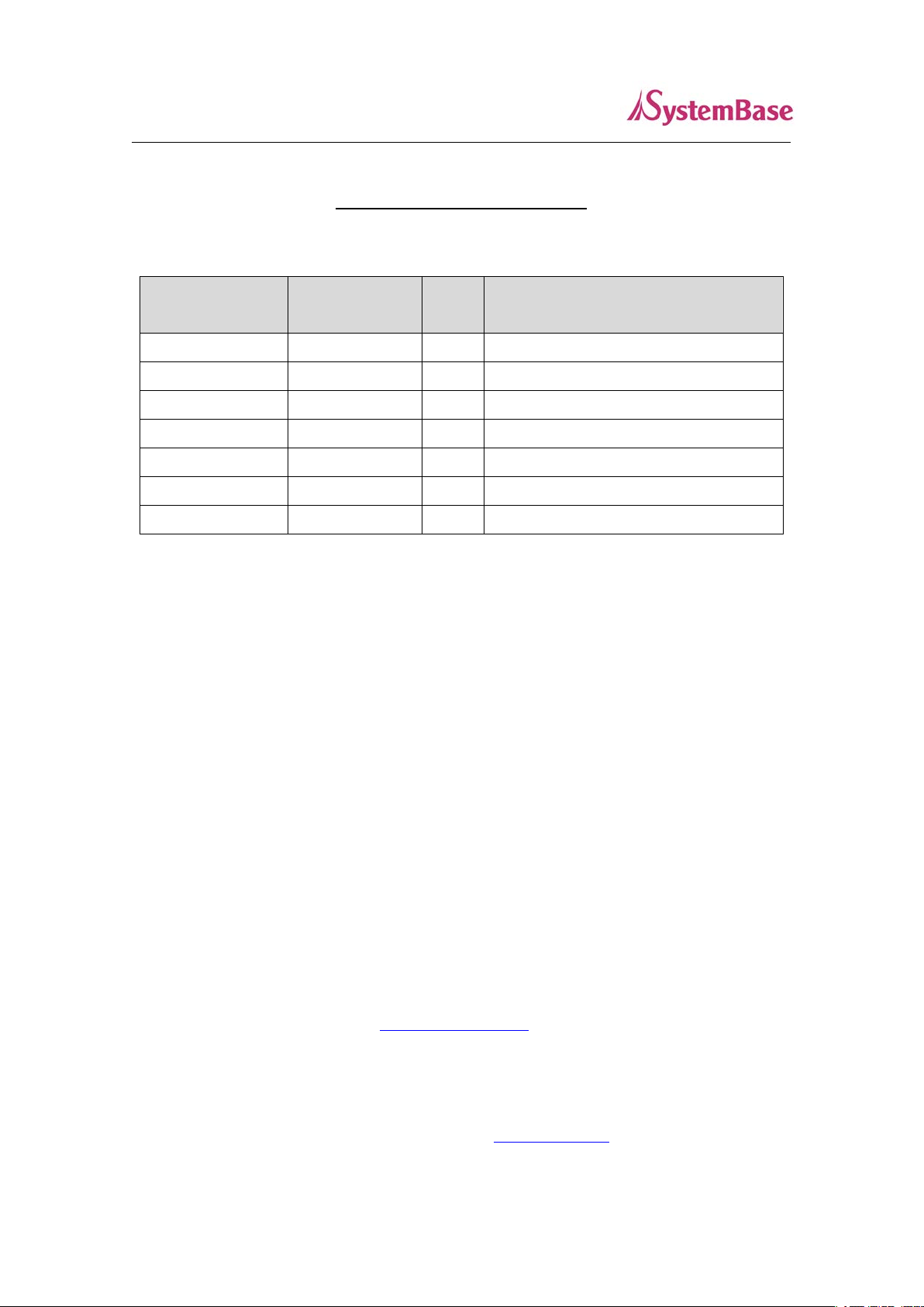
SG-3011DCL/232 related documents
The following table summarizes documents included in the SG-3011DCL/232 document set.
Document Description
User Guide
COM Port Redirector
User User Manual
TestView User Manual
If you need brief information about SG-3011DCL/232 please visit our company website at
http://www.solvline.com/. You can view and/or download documents related t o Ser ialGate series
as well as latest software and firmware updates. Available resources are as follows:
Document Description
SG-3011DCL/232 Spec Sheet SG-3011DCL/232 specifications
SG-3011DCL/232 White Paper
Integration, configuration, and management tasks are
explained for the administrator
Guide COM Port Redirector by SystemBase
Description of TestView for testing:
COM port, TCP , UDP
Deals with background and technology past, present ,
and future of device servers along with the overview
All doc uments ar e updated prom ptly, so check for the recent doc ument upda te. The c ontents in
these documents are subject to change without any notice in advance.
of market environment.
7
Page 8

SerialGate
User Guide
Technical Support
There are three ways you can get a technical support from SystemBase.
First, visit our website http://www.sysbas.com/ or http://www.solvline.com/
Support’ menu. There you can read FAQ and ask your own question as well.
Second, you can e-mail our technical support team. The mail address is tech@sysbas.com
kind of inquiries, requests, and comments ar e welcome.
Finally, you can call us at the technical support for immediate help. Our t echnical suppor t team
will kindly help you to get over with the problem. The phone s upp ort is av ai lable f r om Monday to
Friday 09:00 AM to 06:00P M. W e ar e not ava ilabl e during holidays in Korea. The phone number
is +82-2-855-0501 (Ext. 1). Do not f orget to dial the ext ensio n n umber after getting the welcome
message.
and go to ‘Technical
. Any
8
Page 9

SerialGate
User Guide
2. Getting Started
This chapter includes SerialGate over view, main and distinctive featur es, package co ntents for
each product, and application fields.
Overview
SG-3011DCL/232 provides network connectivity to various serial devices (security devices,
communication peripher als, modems, data printing devices, industrial metering devices, etc.).
SerialGate supports RS-232 serial communication standards under various communication
speed, meanwhile auto-sensing 100baseTX Fast Ethernet and 10baseT Ethernet connection.
Features
Various features of SerialGate make it a universal yet distinctive device server solution. Here we
present main features of SG-3011DCL/232. Others will explicitly appear throughout this guide.
- Max 921.6Kbps serial speed
- RS-232
- 10/100Mbps Ethernet port
- COM Port Redirector for better adaptability
- Configurable through the Web
9
Page 10
SerialGate
User Guide
Package Contents
SG-3011DCL/232 package is as follows. Please check all the contents in the box.
SG-3011DCL/232, 1 unit
A Class Device
This device is register e d o n l y for off ice us e, an d bo th t he s el ler and the user must be aware of
this. If not correctly sold or purchased, please exchange with home use device.
10
Page 11

SerialGate
User Guide
INTERNET
LAN
LAN
PSTN
HOST
PC
Remote
Host PC
Serial Device Serial Device
Modem
Modem
Serial Gate
Application
SG-3011DCL/232 can be utilized for various fields.
Network Serial Communication
When the PC and SG-3011DCL/232 are connec ted to the net work , and the user gets an acces s
to a device connected to SG-3011DCL/232 from the PC.
11
Page 12

SerialGate
User Guide
Tunneling Serial Communication
SG-3011DCL/232 enables a connection n ot restr icted to dis tanc e betwee n PC an d serial d evice.
To enable this feature, a user should change its setting to TCP Server – TCP Client mode or
UDP Server – UDP Client mode referring to Chapter 5 of this manual.
12
Page 13

SerialGate
User Guide
INTERNET
LANLAN
HOST
PC
Remote
Host PC
Serial Device
Serial Gate
COM(3)
COM(3)
Serial Device
COM Port Redirection
With COM Port Redirecti on, a user can use serial port connected to Ser ialGate on the network
as if it is a serial port on PC.
Factory / Industrial Automation
PLC, Robot arms, Human-Machine Interface, Warehouse rails
Medical instruments, Inspection equipment controllers
Alarming units
Home Appliances / Electronic Devices
Power controller, gaming machines
Scales, Gas detection units, Water & pollution metering devices
Data collection and distribution units
Financial / Building Automation
Card readers, Barcode scanners, Kiosks, Point-Of-Sale related devices
Serial printers, Cash registers, Credit card authorization terminals
Biometric detection units, Security devices
13
Page 14

SerialGate
User Guide
3. Hardware Content
This chapter provides hardwar e information of Serial Gate including block dia gram, layout, pin
specification, dimensions and other hardware-r e lat ed i s sues .
SG-3011DCL/232 exterior
14
Page 15

SerialGate
User Guide
Red blinks when data transmitted
Yellow Green blinks when data received
Serial Port: RS232 (DB-9 MALE)
Power Connector: 12 V DC Adapter (Inner: +, Outer: -)
Reset Button: When pressed and released, SG-3011DCL/232 will reboot.
LED: O peration status of SG-3011DCL/232. N ext section describes the meani ng of each
LAN port: 8-pin RJ45 jack connects SG-3011DCL/232 to networking devices such as
LED display status.
Ethernet card, hub, and router.
SG-3011DCL/232 LED
LED Name Status Operation
1 RDY Blink
2 SRL Blink
LAN Port
3
(Left Green)
LAN Port
4
(Right Orange)
When powered on, it will stay on for few seconds and starts
to blink when booting is complete.
On 100baseT connection detected & LAN data transferred
Off
On Network connected
Off
Blink
10baseT connection detected & LAN data transferred
Network disconnected
LAN data being transmitted
15
Page 16

SerialGate
User Guide
Serial Port Pin Description
RS-232
Pin No. Signal Description
1 DCD Data Carrier Detection (Input)
2 RXD Receive Data (Input)
3 TXD Transmit Data (Output)
4 DTR Data Terminal Ready (Output)
5 GND Ground
6 DSR Data Set Ready (input)
7 RTS Request to Send (Output)
8 CTS Clear to Send (Input)
9 RI Ring Indicator (Input)
16
Page 17

SerialGate
User Guide
4. Make Connection
This chapter explains how to install SG-3011DCL/232. It deals with LAN and serial connection guides
for SG-3011DCL/232 to operate together with the ta rget serial device .
Before connection
In order to connect SG-3011DCL/232 to the network, you need to use RJ45 Ethernet port. It supports
both 10Mbps and 100Mbps Ethernet connection (auto-sensing). Since L AN por t in SG-3011DCL/232
supports MDIX, it automatically detects any kind of cable. (Cross or direct LAN cable) Plug one end of
a LAN cable to SG-3011DCL/232 and the other end to a hub, switch, or a ny other netw ork device.
Booting for the first time
First of all, please make sure that the power input you supply to the module is corresponding with the
SG-3011DCL/232 that you have. If an appropriate power input has been successfully supplied, SG3011DCL/232 will power on and sta rt booting.
Although there is no LED to check the power status, you can check it by LEDs on the RJ45 Ethernet
port. LED status operation i s desc ribed in Chapte r 3. Har dware De scription.
An IP address is required to access web interface in SG-3011DCL/232 command-line configuration
tool. By factory default, a static IP address is assigned to SG-3011DCL/232. After the initial conne ction ,
you can either manually assign a different IP address or set SG-3011DCL/232 to automatically get an
IP address from a DHCP server. While this depends on your network environment and policy, it is
strongly recommended that a u ser a ssigns SG-3011DCL/232 with a unique static IP.
Make connection
In order to view current settings or modify them in SG-3011DCL/232, you need to make a Web
connection to it. IP address is required i nformation to make the connection.
If the LAN port in SG-3011DCL/232 uses assigned IP address from DHCP server or is set to a fixed IP
17
Page 18

SerialGate
User Guide
address, SG-3011DCL/232 supports the following options in case that a user does not know IP
address.
Default IP A ddress: 192 .168.0.223
The default IP address set for SG-3011DCL/232 is 192.168.0.223. To connect to t his addr ess, s ome
changes are needed to be made from the P C. Pleas e refer to follow ing example.
18
Page 19

SerialGate
User Guide
5. Configure through the Web
This chapter explains how to connect SG3011DCL/232 through the Web.
Connection
Open a web browser and type the IP address of the SG-3011PCL. A login window, shown below, will
appear. The initial ID and password are “serialgate” and “99999999” without quotes. The ID and
password can be modified once logged in.
Network Setting
After logged in, the ‘Network Setting’ page will be displayed. Every values in here except the MAC
address can be modified. The page is shown as below.
19
Page 20

SerialGate
User Guide
In Network Setting, y ou can set y our devi ce for pre ferred netwo rk envi ronment or manage it. After
changing the settings, cli ck the [Submit] bu tton to s ave and use the Reboot from the menu to res tart
the device. If you exi t without s aving the modified configuration, i t wil l be los t.
If modified value is not saved by pressing the [Submit] button, the [Cancel] button can be used
to revert the value back to the previous ones.
The summary for Network Setting page is shown below .
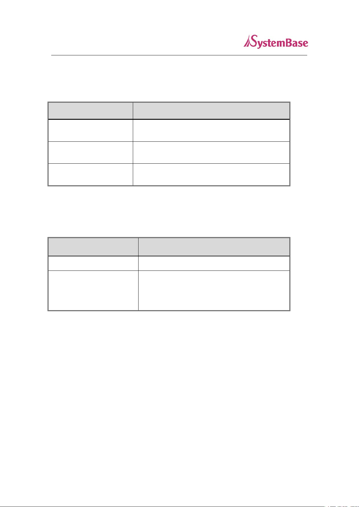
Menu Default Description
Device
SerialGate Name the device
Name
Unique
MAC Address
Address
Connection
Static Choose whet her to lea ve it as Static IP type or DHCP type
Type
IP Address 192.168.0.223
Subnet Mask 255.255.255.0
Gateway 192.168.0.254
Display the MAC Address
Set current IP address
(If the connection type is Static IP, you can set the IP
address, but if it is set to DHCP, you cannot change the
value.)
Set current Subnet mask
(If the connection type is Static IP, you can set the subnet
mask address, but if it is set to DHCP, you cannot change
the value.)
Set current Gateway address
(If the connection type is Static IP, you can set the gateway
address, but if it is set to DHCP, you cannot change the
value.)
DNS 168.126.63.1 IP address for DNS (Domain Name Service)
20
Page 21

SerialGate
User Guide
Serial Setting
In Serial Setting, you can set operation environment of your device. After changing the settings, click
the [Submit] button to save and use the Reboot from the menu to restart the device. If you exit without
saving the modified con figuration, it w ill be lo st.
If modified value is not saved by pre ssing the [Submit] button, the [Cancel] button can be used to r evert
the value back to the p revious ones .
21
Page 22

SerialGate
User Guide
The summary for Setup menu is shown below.
Menu Default Description
Set protocol to be used in the serial ports
Select the operation protocol that will be applied in the serial port.
COM Redirector
Use the serial port of SerialGate as a virtual COM port in Windows
/2000/XP/2003/Vista/7/8.
TCP Server
SerialGate works as a socket server, waiting for the client
connection on the network. Socket number for awaiting connections
can be set in ‘Local socket port’ field. After socket connection, data
between socket and serial port will be transmitted.
TCP Client
Operation
Mode
COM
Redirector
SerialGate acts as a socket client in this mode. It tries to connect to
the server IP address and the socket number assigned when a
certain server waits for connection on the network.
All data between the socket and the serial port is transferred
untouched after the socket connection is established.
UDP Server
SerialGate works as a UDP server, waiting for UDP connection from
the client on the network.
Socket number for awaiting connections can be set in ‘Local socket
port’ field.
Once a UDP packet is received to the socket that waits for the
connection, the data is transmitted to the serial port. The data input
from the serial port is put into UDP packets, which eventually are
sent to the client.
UDP Client
When the data is input to the serial port, UDP packets are sent
using the preset IP address and the socket number of the server. IP
address and port number of the server that needs to connect are
set from the ‘Target IP/Port’.
Set interface for serial port.
Interface RS232
For RS-232 model, it is fixed to RS-232.
22
Page 23

SerialGate
User Guide
Menu Default Description
Set the socket number for the port. TCP server and UDP server
Local Port 4001
Target IP 0.0.0.0
Target
4001 In TCP Client, UDP Client, set the port number of the target device.
Port
Latency
0
Time
operation mode makes use of this port for awaiting network socket
connections.
In TCP Client, UDP Client mode, set the IP address of the target
device.
This needs to be set when consecutive data from the given serial
port needs to be transmitted to socket at once.
For example, if 100 bytes of character string are to be transmitted
from the serial device to a server through SerialGate, bypass is set
to 0 for the latency time. Although it provides immediate sending
through SerialGate, the server could be received a lot parts of
divided packets.
If the latency time is not 0, SerialGate will wait for the time and
check new data. If there is new data, SerialGate repeatedly wait for
the time. Otherwise, SerialGate will transfer the buffered data, but it
could not run in real time.
Baud
9600 bps
Rate
Data Bits 8 Fixed to 8.
Stop Bits 1 Set the number of stop bits (Options: 1, 2)
Parity No Set parity bit check scheme. (Options: No, Odd, Even)
Flow
None
Control
Set serial communication speed
(Options: 150, 300, 600, 1200, 2400, 4800, 9600, 19200, 38400,
57600, 115200, 230400, 460800, 921600 bps)
Set the flow control scheme.
(Options: None, RTS/CTS)
23
Page 24

SerialGate
User Guide
Factory Default
When factory default i s executed, eve ry values set fo r Serial Gate will be e rased and g o back to the outof-the-box set tings. Once it is e xecuted, the value s cannot be recovered
If this button is pres sed for longe r then 3 second, Se rialGate will restore factory default settings.
Pressed for Action Result
Less than 3 seconds Press and hold
3 seconds or more Reverts all settings to the factory default
then release
after required
time period
Restarts the SerialGate
values.
Reboot
The device reboots
After modifying the settings, use ‘submit’ to save the value then reboot the SerialGate.
24
Page 25

SerialGate
User Guide
6. Application Example
SerialGate can be used in many practi cal appli cations in variou s fields. Here we p resent so me of them.
Com Port Redirector
With COM Port Redirection, a user can use serial port connect ed to Serial Gate on the netw ork as i f it is
a serial port on PC.
Install COM Port Redirector and set the following steps. (For installation, please refer to Com Port
Redirector manual enclosed in CD.
In the picture below, IP address of SerialGate is 192.1 68.0 .223, and the first serial po rt is bei ng u sed. A
user can open COM 1 and use serial device connected to SerialGate
25
Page 26

SerialGate
User Guide
In order to correspond to the Redirector setting of PC, change the setting in the first serial port of
SerialGate as follows.
26
Page 27

SerialGate
User Guide
TCP_Server (TCP/IP connection from PC to SerialGate)
In socket program from the PC, connect the first serial port of SerialGate.
Since sock et number for the firs t port of SerialGate is default 4001, try to connect to IP address and
socket number 4001 in Serial Gate when connecting from the PC to the SerialGate. As shown below,
change the Operation Mode to TCP_Server and confirm the s ocket numb er waiting for connection.
Check the communication speed of a serial device to be connected to serial port, and set it to Com
Specification.
27
Page 28

SerialGate
User Guide
TCP_Client (TCP/IP connection from SerialGate to PC)
SerialGate conne cts to TCP/IP through the socket program in PC.
Since it is a connection from SerialGate to a PC, change the Operation Mode to TCP_Client and
register PC’s IP address and socket number to be connected. Check the communic ation speed of a
serial device to be connected to serial port, and set it to Com Specification.
28
Page 29

SerialGate
User Guide
Troubleshooting
This section describes procedures for troubleshooting problems you may encounter with
SerialGate.
Troubleshooting Installation Problems
If you cannot access the connected ser ial device via SG-3011DCL/232, first check the ne twork
connection and cabling.
Check the physical cabling to ensure all cables are plugged in (Ethernet and DB-9 serial
cable)
If the appropriate LEDs are not illuminated, then there is probably a bad 10baseT or
100baseTX cable, or the hub port is bad. If possible, try a different cable and hub port, or
try connecting a different device to the cable.
Verify that you are using the correct values for both IP Address and Port Number.
If you are using a hub, verify that the hub port is operating correc t l y by trying SG-3011DCL/232
on a different port.
Troubleshooting Network Configuration Problems
If you are using TCP/IP, make sure that your computer and SG-3011DCL/232 are on the
same IP segment or can reach each other with a PING command from the host. The IP
address you assign to SG-3011DCL/232 must be on the same logical network as your host
computers (e.g., if your computer has an IP address of 192.189.207.3 and the subnet mask
of 255.255.255.0, SG-3011DCL/232 should have an IP address of 192.189.207.x, where x
is an integer between 1 and 254), or you must properly configure your router address to
work with SG-3011DCL/232.
If your SG-3011DCL/232 is set to auto or DHCP for obtaining an IP address, it is possible
that IP address in SG-3011DCL/232 can be changed. Either configure your DHCP server
to give SG-3011DCL/232 a permanent lease, or configure SG-3011DCL/232 to be on a
STATIC IP address outside the scope of the DHCP addresses.
The problem may be the result of mismatched or duplicate IP addresses. Verify that the IP
address is correctly loaded into SG-3011DCL/232 (via the displayed or printed configuration
information or through the remote console), and make sure that no other nodes on the
network have this address (duplicate addresses are the biggest cause of TCP/IP
29
Page 30

SerialGate
User Guide
Also verify that the host computer and SerialGate are using the same subnet masks (for
If the wrong IP address is loaded, check your network for DHCP server, and make sure that
Troubleshooting Windows Problems
If you are having trouble accessing the connected serial device through Windows,
connectivity problems). If the IP address is not correct, then check whether the loading
procedure was properly executed.
example, if SG-3011DCL/232 has a subnet mask of 255.255.255.0, the host must have the
same subnet mask) or that the router is properly configured to pass data between the two
devices.
the server is not set up to load wrong IP addresses into SG-3011DCL/232.
ensure you can ping SG-3011DCL/232 using the command PING x.x.x.x, where x.x.x.x
is the IP address of SG-3011DCL/232. If you cannot ping SG-3011DCL/232, you will not
be able to access the serial device.
If you are running COM port redirector and the software reports an error, verify that the
correct virtual COM port is being used when the application runs. Verify that your
application’s COM port settings have been changed to use the virtual COM ports.
30
Page 31

SerialGate
User Guide
Serial Port
Product Specification
Communication
LAN Port
Network Static IP, DHCP IP
Number of Serial Port 1 Port
Speed 150 bps ~ 921 Kbps
10/100Mbps RJ-45 Port x 1EA
Hardware
Power 5V DC Input
Dimension 46(W) x 77.5(L) x 25(H)mm
Weight 32.1g
Operation
Temperature
Signals RXD, TXD, RTS, CTS, DCD, DTR, DSR, RI
Humidity Max 90% non-condensing
LED
0℃ ~ 70℃
RDY (Green), SRL (Red/Yellow Green)
RJ-45 Connector LED : Speed (Green), Link/Activity (Yellow)
Protection
± 15kV ESD Protection
Reset Button
Pressed for Action Result
Less than 3 seconds Press and hold
3 seconds or more Reverts all settings to the factory default
then release
after required
time period
Restarts the SerialGate
values.
31
Page 32

SerialGate
User Guide
Software
Ordering Information
Protocol TC P, U D P, I C M P, DHCP, HTTP
Utility Redirector, TestView
Configuration from Web, SGConfig
SG-1010/232-RJ 1 x Serial RJ-45 Port (RS232 only)
SG-1010/Combo-RJ 1 x Serial RJ-45 Port (RS422/RS485 selectable)
SG-1010/ALL 1 x Serial DB-9 & T/B Port (RS232/RS422/RS485 selectable)
SG-1010W/ALL 1 x Serial DB-9 & T/B Port (RS232/RS422/RS485 selectable)
SG-1020/232-RJ 2 x Serial RJ-45 Port (RS232 only)
SG-1020/Combo-RJ 2 x Serial RJ-45 Port (RS422/RS485 selectable)
SG-1020/ALL 2 x Serial DB-9 & T/B Port (RS232/RS422/RS485 selectable)
SG-1020W/ALL 2 x Serial DB-9 & T/B Port (RS232/RS422/RS485 selectable)
SG-1040/232 Series 4 x Serial RJ-45 Port (RS232 only)
SG-1040/Combo Series
SG-1080/232 Series
SG-1080/Combo Series
SG-1160/ALL
4 x Serial RJ-45 Port (RS422/RS485 selectable)
8 x Serial RJ-45 Port (RS232 only)
8 x Serial RJ-45 Port (RS422/RS485 selectable)
16 x Serial RJ-45 Port (RS232/RS422/RS485 selectable)
SG-3011DCL/232
SG-3011PCL
1 x Serial RJ-45 Port (RS232 only)
1 x Serial Pin Header
(RS232, RS-422/485, TTL selectable)
32
 Loading...