

Page 1

PB-3010/3020+
User Guide
English Ver 1.2a
2008. 6. 5
Page 2

Portbase User Guide
Revision History
Revision Date
June 5, 2006 1.0 All Initial release by tsum
June 20, 2006 1.1 All Context amendment by shlee
June 5, 2008 1.2a All Context amendment by shlee
Document
Version
Pages
Description
Copyright 2008 SystemBase Co., Ltd. All rights reserved.
Website http://www.sysbas.com/
Tel 02-855-0501
Fax 02-855-0580
th
16
Fl. Daerung Post Tower-1, 212-8, Guro-dong, Guro-gu, Seoul, Korea
For any inquiries or comments, contact to tech@sysbas.com
2
Page 3

Portbase User Guide
Contents
Chapter 1 Introduction 5
1. About This Document 5
2. Who Should Read This Document? 5
3. Document Structure 6
4. Portbase Documents 7
5. Technical Supports 8
Chapter 2 Getting Started 9
1. Overview 9
2. Features 9
3. Package Checklist 10
4. Applications 11
Chapter 3 Hardware Description 12
1. The Exterior 12
2. LED / RESET 14
3. Serial Port Pin Specifications 15
Chapter 4 Installation 16
1. Installing Portbase 16
2. Portbase Connection 17
Chapter 5 Configuration via Web 20
1. Connection 20
2. Setup Menu 21
3. Network Settings 22
3
Page 4

Portbase User Guide
4. Serial Settings 25
5. Admin Settings 30
6. Change Password 31
7. Update Firmware 32
8. Factory Default 33
9. Save & Reboot 34
Chapter 6 Configuration via Telnet 35
1. Connection 35
2. View commands 36
3. Network commands 36
4. Serial commands 37
5. Admin commands 41
6. System commands 41
Chapter 7 Appendix 42
1. Troubleshooting 42
2. Technical Specifications 44
3. approvals 46
4
Page 5

Portbase User Guide
Chapter 1 Introduction
This chapter is an introduction to SystemBase device server Portbase series and this document.
1. About This Document
This guide is designed for users of Portbase, who are in charge of connecting to and communicating with
Portbase, setting Portbase’s configurations, status monitoring, firmware update, and other administration
work.
2. Who Should Read This Document?
This guide is designed for Portbase users and administrators. It is strongly recommended that anyone
trying to apply, use, and maintain Portbase read this document. This guide deals with the hardware-level
integration issues and software-level configuration tips. It will be a great starting point for any
administrators who want to easily monitor and control Portbase and its connected devices.
5
Page 6

Portbase User Guide
3. Document Structure
Introduction (Chapter 1) is a preface with general information and introductory notices.
Getting Started (Chapter 2) gives a brief introduction to Portbase series, including features and
applications.
Hardware Descriptions (Chapter 3) explains about the layout and pin specifications with block diagram
and drawings.
Installation (Chapter 4) helps you to connect Portbase to serial and network environment. It ends up with
first time boot-up and status check.
Configuration via Web (Chapter 5) provides menu-by-menu guide for setting up the operation
environment for Portbase via web browser.
Configuration via Telnet (Chapter 6) provides a list of commands for setting up the operation
environment for Portbase via Telnet.
Appendix (Chapter 7) provides firmware update guides and technical specifications for detailed
information.
6
Page 7

o
Portbase User Guide
4. Portbase Documents
The following table summarizes documents included in the Portbase document set.
Document Name Description
Integration, configuration, and
User Guide
management tasks are explained for the
administrator
Portview User Manual
COM Port Redirector
User Manual
TestView User Manual
If you need brief information on Portbase or device servers in general, please visit our company website
at http://www.sysbas.com/
software and firmware updates. Available resources are as follows:
Document Name Description
Portbase Spec Sheet Specifications for Portbase products
Portbase White Paper
. You can view and/or download documents related to Portbase as well as latest
Guide for SystemBase device server
management application Portview
Guide for SystemBase COM Port Redirector
User Manual for testing Com port Redirector , TCP
Server/Client , UDP Server/Client
An easy reading for any
server.
Deals with background and technology
Past, present, and future of device
ne new to device
servers along with the overview of
market environment
All documents are updated promptly, so check for the recent document update. The contents in these
documents are subject to change without any notice in advance.
7
Page 8

Portbase User Guide
5. Technical Supports
There are three ways you can get a technical support from SystemBase.
First, visit our website http://www.sysbas.com/
FAQ and ask your own question as well.
Second, you can e-mail our technical support team. The mail address is tech@sysbas.com
inquiries, requests, and comments are welcome.
Finally, you can call us at the customer center for immediate support. Our technical support team will
kindly help you get over with the problem. The number to call is 82-2-855-0501 (Extension number 22 5).
Do not forget to dial the extension number after getting a welcome message.
and go to ‘Technical Support’ menu. There you can read
. Any kind of
8
Page 9

Portbase User Guide
Chapter 2 Getting Started
This chapter includes Portbase overview, main and distinctive features, package contents for each product,
and application fields.
1. Overview
Portbase provides network connectivity to various serial devices (security devices, communication
peripherals, modems, data printing devices, industrial metering devices, etc.). Portbase supports RS232,
RS422, and RS485 serial communication standards under various communication speed, meanwhile autosensing 100baseTX Fast Ethernet and 10baseT Ethernet connection.
2. Features
Various features of Portbase make it a universal yet distinctive device server solution. Here we present
main features of Portbase. Others will explicitly appear throughout this guide.
- Max 921.6Kbps serial speed
- Software configurable RS232/422/485 interfaces
- 10/100Mbps Ethernet port
- SystemBase COM Port Redirector for better adaptability
- Extensive configuration and monitoring with Portview
- Firmware upload with Web and FTP
- Configuration with Web, Telnet, SNMP, and Portview
- Lots of customizing options
9
Page 10

Portbase User Guide
3. Package Checklist
Portbase package is composed of following components. Make sure every component is included with
your package.
All packages include a module and a CD with utilities and documents.
Portbase device 1pc (RS232 model or Combo(RS422/ RS485) model)
Cross LAN Cable 1pc
Power Adapter 1pc
CD (utilities and documentations)
A-Class Device
This device is registered only for office use, and both the seller and the user must be aware of
this. If not correctly sold or purchased, please exchange with home use device.
10
Page 11

Portbase User Guide
4. Applications
Portbase can be applied to many practical applications in various fields. Here we present some of them.
Factory / Industrial Automation
PLC, Robot arms, Human-Machine Interface, Wareho use rails
Medical instruments, Inspection equipment controllers
Alarming units
Home Appliances / Electronic Devices
Power controller, Gaming machines
Scales, Gas detection units, Water & pollution metering devices
Data collection and distribution units
Financial / Building Automation
Card readers, Barcode scanners, Kiosks, Point-Of-Sale related devices
Serial printers, Cash registers, Credit card authorization terminals
Biometric detection units, Security devices
11
Page 12
Portbase User Guide
Chapter 3 Hardware Description
This chapter provides Portbase's hardware information, including block diagram, layout, pin
specifications, dimensions and other hardware-related issues.
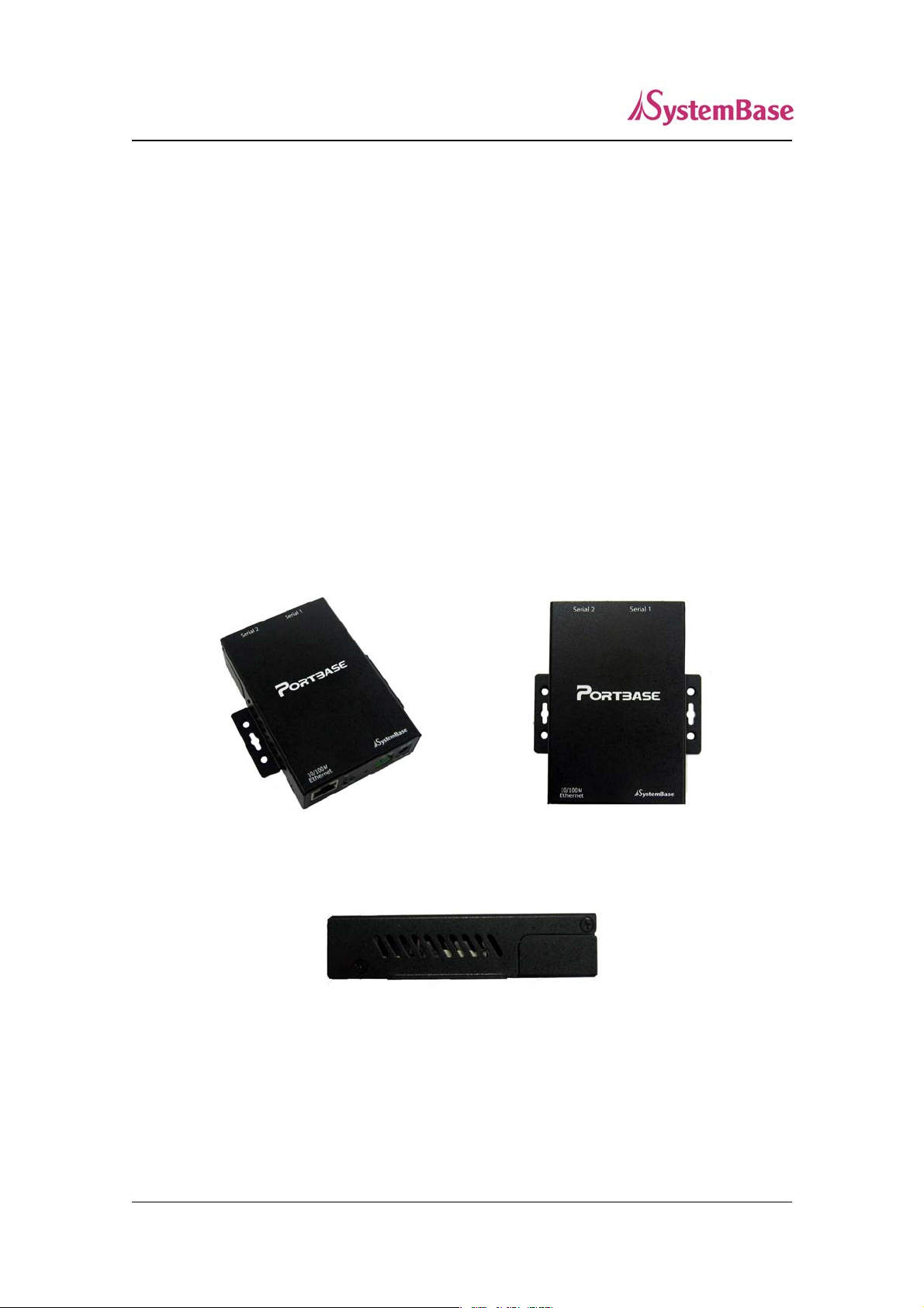
1. The Exterior
< full view > < top view >
< side view >
12
Page 13
Portbase User Guide
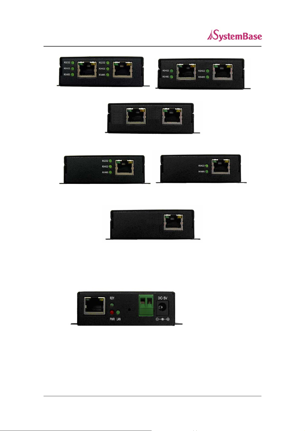
< PB-3020+ All Serial Port side > < PB-3020+ Combo Serial Port side >
< PB-3020+ RS232 Serial Port side >
< PB-3010+ All Serial Port side > < PB-3010+ Combo Serial Port side >
< PB-3010+ RS232 Serial Port side >
Serial port – 8-pin RJ-45 jack and check the interface type(RS232/RS422/RS485)
with green LED
< LAN port side >
Power connector – for connection of DC5V adapter cable
Terminal block power connector – for connection of terminal block power cable
13
Page 14
Portbase User Guide
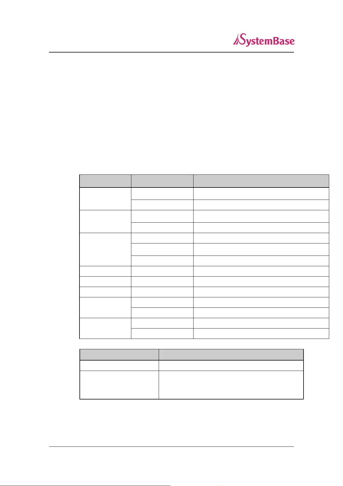
Reset button – Portbase reboots if this button is pressed for less than 5 seconds. If
pressed for longer than 5 seconds, Portbase will restore factory default settings.
LED – Operation status of Portbase. Next section describes the meaning of each LED
display status.
LAN port – 8-pin RJ45 jack which is used when connecting Portbase to network
devices such as Ethernet card, hub, and router.
2. LED / RESET
<LED display status>
LED Status Meaning
PWR
(R
ED)
LAN
(Green)
RDY
(Green)
RS232 On
RS422 On
RS485 On
Serial Tx/Rx
LAN Tx/Rx
<Reset button features>
On
Off
Off
On
Blinking
On
Off
Green Blinking
Orange Blinking
Green Blinking
Orange Blinking
Operation Result
Power supplied to the device
No power supplied to the device
No active network connection
Network activated
IP Configuration
Normal operation
System error
Serial port set to RS232 mode
Serial port set to RS422 mode
Serial port set to RS485 mode
Serial data transmitted
Serial data received
10baseT connection detected & LAN data transferred
100baseT connection detected & LAN data transferred
Pressed for less than 5 seconds Restart Portbase
Pressed for more than 5
seconds
Restore factory default settings of Portbase. The device will
automatically reboot.
14
Page 15

Portbase User Guide
3. Serial Port Pin Specifications
- RS232 - RS422 - RS485
1 RTS 2 DTR
3 RXD 4 DSR
5 TXD 6 GND
7 DCD 8 CTS
1TX- 2
3 RX+ 4 RX-
5TX+ 6GND
78
Pin Specifications
1 RTS RS232 Signal (RequestTo Send)
2 DTR RS232 Signal (Data Terminal Ready)
3 RXD RS232 Signal (Receive Data)
4 DSR RS2 32 Signal (Data Set Ready)
5 TXD RS232 Signal (Transmit Data)
6 GND RS232 Signal (Signal Ground)
7 DCD RS232 Signal (Data Carrier Detect)
8 CTS RS232 Signal (Clear To Send)
1TRx- 2
3 4
5TRx+ 6 GND
7 8
RX+ RS422 Signal (Receive Data +)
TX+ RS422 Signal (Transmit Data +)
TX- RS422 Signal (Transmit Data -)
RX- RS422 Signal (Receive Data -)
TRX+ RS485 Signal (Transmit/Receive Data +)
TRX- RS485 Signal (Transmit/Receive Data -)
15
Page 16

Portbase User Guide
Chapter 4 Installation
This chapter explains how you can make Portbase to communicate. It deals with LAN and serial
connection guides for Portbase to operate together with the target serial device.
1. Installing Portbase
Follow the steps below to install Portbase. In most cases, Portbase’s factory default settings should be
sufficient for most serial connections; however, some of the configuration settings may have to be
changed for your particular installation. Portbase can be wall mounted, set on the desktop, or mounted
using the optional DIN rail kit.
1. Before attempting to install Portbase, make sure you have installed and set up your serial equ ipment as
described in the documentation that came with the device.
2. Write down the 12-digit MAC (Media Access Code) address printed on the label located on the bo ttom
of Portbase. You may need this number in order to configure Portbase.
3. Connect Portbase to your equipment using an RJ-45 serial connector.
4. Plug Portbase power supply adapter into a suitable AC receptacle, and then plug the power supply
cable into Portbase. Portbase will run through a sequence of power-up diagnostics for a few seconds.
If Portbase is operating properly, the RDY LED will blink constantly in a regular
pattern. PWR LED should also be on.
If the RDY LED does not blink continuously in a regular pattern, a problem exists. If
this is the case, try powering the unit OFF and then ON again. If the problem persists,
refer to the Troubleshooting section in this User Guide.
5. Connect Por tbase to your network throug h a switch or hub using a category 5 (CAT5) Ethernet cable.
Portbase’s IP address must be configured before a network connection is available. If your network
offers DHCP (Dynamic Host Configuration Protocol), Portbase will automatically search for a DHCP
server upon power up and obtain an IP address. If your network does not offer DHCP, a static
(fixed) IP address must be assigned (see your system administrator for assistance). In most cases, a
fixed IP address is preferred because a DHCP server may not always assign the same IP address to
Portbase when Portbase is powered ON.
16
Page 17

Portbase User Guide
NOTE: The IP address must be within a valid range, unique to your network, and in the same subnet as your
PC.
2. Portbase Connection
Follow these steps to connect Portbase to the device and network.
Connection Guide
1) LAN
In order to connect Portbase to network, you need to use RJ45 Ethernet port. I t su ppor ts both 10 Mbps and
100Mbps Ethernet connection (auto-sensing). Plug one end of a LAN cable to Portbase and the other end
to a hub, switch, or any other network device that can provide you with network access.
* If you connect portbase to PC directly, you have to use cross LAN cable.
2) Serial
In order to connect external serial device and Portbase, RJ45 serial cable is required. For pin
specifications and further information, please refer to the Chapter 3. Hardware Descriptions.
First-Time Bootup
Portbase will power on and start booting process when DC adapter (5V) is connected . Operation status
can be monitored by LED displays. For more information on LED displays, please refer to the Chapter 3.
Hardware Descriptions.
An IP address is required to access Portbase's web interface or telnet command-line configuration tool.
By factory default, Portbase is assigned a static IP address. After the initial connection, you can either
manually assign a different IP address or set Portbase to automatically get an IP address from a DHCP
server.
The factory default IP address of Portbase : 192.168.1.71(10.10.1.1)
17
Page 18

Portbase User Guide
Portbase’s default IP address is set to 10.10.1.1. In order to connect with this address, you need to change
network configurations so that your PC can connect to the IP 10.10.1.1. Please refer to an example below,
and note that values doesn’t necessarily have to be identical to the example below.
After modifying the IP address of Portbase, it may lead to difficulties if you do not remember the IP
address. To prevent such accidents, Portbase always remembers a factory default address 10.10.1.1
18
Page 19

Portbase User Guide
Now you are ready to connect to Portbase! There are three options to configure Portbase.
Web: You can easily configure Portbase with web interface, accessible from any web browser. For more
information, please refer to Chapter 5. Configuration via Web.
Telnet: You can configure Portbase with commands after accessing Portbase through Telnet. For more
information, please refer to Chapter 6. Configuration via Telnet.
19
Page 20

Portbase User Guide
Chapter 5 Configuration via Web
1. Connection
Open your favorite web browser and enter the IP address of Portbase to access Portbase’s web manager.
Once you are successfully connected, the following front page will show up. You need to enter
appropriate username and password to login.
Please note that this username and password is used as authentication method for Telnet as well. This
means if username or/and password has been modified from the web interface, modified values have to be
entered to connect to Telnet, and vice versa.
Factory default username: portbase
Factory default password: 99999999
20
Page 21

Portbase User Guide
2. Setup Menu
If login process is successful, you will see a web manager’s main page, showing summary of your device.
On the left, you will see a setup menu, and you can navigate through these options.
Summary : View a summary of Portbase.
Network Settings : Configure network connection settings.
Serial Settings : Configure detailed operation environment for serial communication.
Change Password : Change ID and password for both Web and Telnet interface.
Update Firmware : Update Portbase’s firmware.
Factory Default : Restore all the factory default settings.
Save & Reboot : Save the configurations and reboot Portbase.
21
Page 22

Portbase User Guide
3. Network Settings
Configure general network environment and network management. After changing values, you need to
click ‘Submit’ button. Then you will see the same page with modified values. Please note that you have to
‘Save & Reboot’ in order to see these ch anges in effect. Changes will be discarded if you do not save
current settings.
Network Configuration
z Connection Mode (Default: Static)
Options: Static IP / DHCP
IP obtaining method for Portbase’s network connection
z IP Address (Default: 192.168.1.71)
Current IP address Portbase is assigned to.
When connection mode is Static IP, manually enter an appropriate IP address.
22
Page 23

Portbase User Guide
When connection mode is DHCP, current IP is displayed, but it is not editable.
z Subnet Mask (Default: 255.255.255.0)
Current subnet mask Portbase is assigned to.
When connection mode is Static IP, manually enter an appropriate subnet mask.
When connection mode is DHCP, current subnet mask is displayed, but it is not editable.
z Gateway (Default: 192.168.1.1)
Current default gateway Portbase is assigned to.
When connection mode is Static IP, manually enter an appropriate default gateway.
When connection mode is DHCP, current default gateway is displayed, but it is not editable.
z DNS
IP address of DNS server that Portbase uses.
NMS Configuration
If multiple devices are installed and managed together, integration in management is necessary. In
addition, it is often the case when the device reports an erroneous status, figuring ou t the reason for the
failure becomes a time-consuming job. To solve this inefficiency and provide better solution, Portbase
includes Network Management System software, Portview.
z SNMP (Default: Disable)
Options: Enable / Disable
Enable or disable SNMP(Simple Network Management Protocol) support.
MIB-II (RFC 1213): System, Interface, IP, ICMP, TCP, UDP
MIB-I (RFC 1317): Serial Interface
z PortView (Default: Disable)
Options: Enable / Disable
Enable or disable Portview.
When enabled, following configuration options are available.
23
Page 24

Portbase User Guide
z Portview Server IP / Port (Default: 0.0.0.0 / 4000)
Set the IP address and the port number of the PC where Portview in installed. For more
information on Portview, please refer to the Portview User Manual.
z Group (Default: None)
Set the group name for management. 32 Characters at maximum.
z Location (Default: None)
Set the location name for management. 32 Characters at maximum.
24
Page 25

Portbase User Guide
4. Serial Settings
You can set the communication and operation environment for the serial port. After changing values, you
need to click ‘Submit’ button. Then you will see the same page with modified values. Please note that you
have to ‘Save & Reboot’ in order to see these changes in effect. Changes will be discarded if you do not
save current settings.
z Status (Default: Enabled)
Options: Enabled / Disabled
Choose to use or not use this port. You cannot use the port when selecting 'Disab led'.
z Interface (Default: RS232 )
Options: RS232 / RS422 Point To Point / RS422 Multi Drop / RS485 Non-Echo / RS485 Echo
Select the type of serial interface.
25
Page 26

Portbase User Guide
z Operation Mode (Default: COM(Win200x/XP))
Select the operation protocol, which the serial port would use.
J COM(Win200x/XP)
Use the serial port of Portbase as the COM ports of Windows 2000/XP/2003 operated PC.
(Both the data and the signal line information of the serial port can be controlled.)
J COM(Win98/ME)
Use the serial ports of Portbase as the COM ports of Windows 98/ME operated PC. (Both
the data and the signal line information of the serial port can be controlled.)
J TCP Server
Portbase works as a socket server, waiting for the client connection on the network.
Socket number for awaiting connections can be set in ‘Local socket port’ field.
All data between the socket and the serial port is transferred untouched after the socket
connection is established.
J TCP Client
Portbase acts as a socket client in this mode. It tries to connect to the server IP address and
the socket number assigned when a certain server waits for connection on the network.
All data between the socket and the serial port is transferred untouched after the socket
connection is established.
J TCP Multi-Server
Portbase works as a server, accepting up to 5 simultaneous connections from socket
clients.
Data transmitted from Portbase is broadcast to each socket client.
J UDP Server
Portbase works as a UDP server, waiting for UDP connection from the client on the
network.
Socket number for awaiting connections can be set in ‘Local socket port’ field.
Once a UDP packet is received to the socket that waits for the connection, the data is
transmitted to the serial port. The data input from the serial port is put into UDP packets,
which eventually are sent to the client.
J UDP Client
When the data is input to the serial port, UDP packets are sent using the preset IP address
and the socket number of the server.
z Local Socket Port (Default: 4001)
Set the socket number for the port. TCP server and UDP server operation mode makes use of
this port for awaiting network socket connections.
26
Page 27

Portbase User Guide
z Port Alias (Default: Port1)
Port alias name for convenience. 16 Characters at maximum.
z Baud Rate (Default: 9600bps)
Options: 150, 300, 600, 1200, 2400, 4800, 9600, 19200, 38400, 57600, 115200, 230400,
460800, 921600bps
Set communication speed.
z Data Bits (Default: 8)
Options: 5, 6, 7, 8
Set the number of bits in each character size.
z Stop Bits (Default: 1)
Options: 1, 2
Set the number of stop bits.
z Parity (Default: None)
Options: None, Odd, Even
Set parity bit check scheme.
z Flow Control (Default: None)
Options: None, Xon/Xoff, RTS/CTS
Set the flow control scheme.
z Device T y pe (Default: DataOnly)
Options: Data Only, Modem Signals
Set the signal line checking method for the device to be connected to the given serial port.
If the mode is set to Data Only, only Txd, Rxd, and Gnd signal lines are used in inter-device
communication. If the mode is set to Modem Signals, all modem signals except RI(Ring
Indicator) are asserted, tested, and used in communication.
z Remote IP Address / Port (Default: 0.0.0.0 / 4000)
When the Operation Mode is set to TCP Client, set the IP address and the socket number to
connect to.
27
Page 28

Portbase User Guide
z Alive Check Time (Default: 0 sec)
When the operation mode is set to TCP Client, TCP Server, TCP Multi-Server, after a certain
amount of time passes without any communication after the socket connection between the
given serial port and the server is established, automatically disconnect the socket connection.
If the value is set to 0, this function is disabled. Va lid from 0 to 32767 seconds.
z MTU (Default: 1 byte)
MTU stands for Maximum Transmission Unit, and this option needs to be set when
consecutive data from the given serial port needs to be transmitted to socket at once. If 100
bytes of character string are to be transmitted from the serial device and MTU is set to ‘100’,
Portbase waits until the entire 100 bytes are received. After receiving 100 bytes, it transmits
this data to the server as a single packet, using the socket. If 200 bytes of character string are
to be transmitted from the serial device, Portbase breaks this data into 2 packets of 100 bytes.
If MTU is set to ‘1’, however, each byte is transmitted right away in a packet, therefore
multiple packets sent to the server. Valid from 1 to 1100.
z Port Login (Default: Disable)
Options: Enable, Disable
When the Operation Mode is set to TCP Server, ask for the username and password when the
client tries to connect.
You can set the username and password if this option is enabled.
z Username (Default: conuser)
When the Operation Mode is set to TCP Server, set the username to ask for. 32 Characters at
maximum.
z Password (Default: 99999999)
When the Operation Mode is set as TCP Server, set the password to ask for. 32 Characters at
maximum.
z Reset Port
Clicking a 'Submit' button with the Reset Port checkbox ch ecked will reinitialize the current
28
Page 29

Portbase User Guide
port.
29
Page 30

Portbase User Guide
5. Admin Settings
Device information and support information settings. After changing values, you need to click ‘Submit’
button. Then you will see the same page with modified values. Please note that you have to ‘Save &
Reboot’ in order to see these changes in effect. Changes will be discarded if you do not save current
settings.
Device Information
z Device Name (Default: Portbase-3020+ or Portbase 3010+)
Name of the current device.
z Firmware Version
Current firmware version.
z Hardware Version
Current hardware version.
z Kernel Version
Current kernel version.
Support Information
z Website
Website for help and support.
30
Page 31

Portbase User Guide
z Contact
Contact information for technical support.
6. Change Password
Change Web/Telnet access username and password. After changing values, you need to click ‘Submit’
button. Then you will see the same page with modified values. Please note that you have to ‘Save &
Reboot’ in order to see these changes in effect. Changes will be discarded if you do not save current
settings.
Default password is ‘99999999’.
31
Page 32

Portbase User Guide
7. Update Firmware
Firmware is an application embedded in Flash memory of Portbase. Set the location of the firmware file
to update, using the ‘Browse…‘ button. The selected firmware will be transferred to Portbase when you
click ‘Start Update’. After the transmission is complete, Portbase will be automatically restarted to
operate with the new firmware.
32
Page 33

Portbase User Guide
8. Factory Default
Restore all the configuration parameters to the factory default values. Clicking on ‘Restore Factory
Defaults’ button will delete all current settings and restore settings to the initial status. Portbase will
automatically reboot. You cannot turn back the decision once you select this option.
33
Page 34

Portbase User Guide
9. Save & Reboot
This option saves changes to the Flash memory and restarts the system to let the changes to take place in
the operation.
z Save and Reboot
‘Save & Reboot’ reboots Portbase after saving changes to Flash memory.
z Reboot without Saving
‘Reboot Only’ option just reboots Portbase without saving changes. This option can be used to
rollback the changes you have mistakenly made.
34
Page 35

Portbase User Guide
Chapter 6 Configuration via Telnet
1. Connection
Open your telnet client and enter Portbase’s IP address to connect. You need to enter appropriate
username and password to login. Please note that this username and password is used as authentication
method for Web as well. This means if username or/and password has been modified from the telnet
interface, modified values have to be entered to connect to web, and vice versa.
Factory default username: portbase
Factory default password: 99999999
With ‘set’ commands, you can configure Portbase’s settings.
With ‘set view’ commands, you can view current Portbase’s settings.
After changing values, you can see modified values with ‘set view’ commands. But be careful because
these values are not in effect unless you issue a ‘set save’ command. Changes will be discarded if you do
not save current settings.
Command notations:
1) set nw mode [ static / dhcp ]: Either enter set nw mode static or set nw mode dhcp
2) set nw ip <IP address>: Enter actual values such as set ip 192.168.1.71
35
Page 36

Portbase User Guide
2. View commands
z set view [ all / nw / serial / admin ]
- set view all : View all current settings.
- set view nw : View current network settings.
- set view serial : View current serial port settings.
- set view admin : View current admin settings.
3. Network commands
Configure general network environment and network management.
z set nw [ mode / ip / subnet / gateway / dns / nms ] <var … >
[ Network Configuration ]
- set nw mode [ static / dhcp ] (Default: static )
IP obtaining method for Portbase’s network connection
- set nw ip <IP Address> (Default: 192.168.1.71)
Set the current IP address Portbase is assigned to.
When line type is Static IP, manually enter an appropriate IP address.
When line type is DHCP, it is no t editable.
- set nw subnet <Subnet mask> (Default: 255.255.255.0)
Set the subnet mask Portbase is assigned to.
When line type is Static IP, manually enter an appropriate subnet mask.
When line type is DHCP, it is no t editable.
- set nw gateway <Gateway address> (Default: 192.168.1.1)
Set the default gateway Portbase is assigned to.
When line type is Static IP, manually enter an appropriate gateway.
When line type is DHCP, it is no t editable.
- set nw dns<DNS address>
Set the DNS address of Portbase.
36
Page 37

Portbase User Guide
[ NMS configuration]
If multiple devices are installed and managed together, integration in management is necessary. In
addition, it is often the case when the device reports an erroneous status, figuring ou t the reason for the
failure becomes a time-consuming job. To solve this inefficiency and provide better solution, Portbase
includes a Network Management System software, Portview.
- set nw nms snmp [ enable / disable ] (Default: disable)
Enable or disable SNMP(Simple Network Management Protocol).
MIB-II (RFC 1213): System, Interface, IP, ICMP, TCP, UDP
MIB-I (RFC 1317): Serial Interface
- set nw nms portview ip <IP Address> (Default: 0.0.0.0)
Set the IP address of the PC where Portview in installed. For more information on Portview,
please refer to the Portview User Manual.
If IP is set to 0.0.0.0, NMS feature is disabled.
- set nw nms portview port <Socket Number> (Default: 4000)
Set the port number of the PC where Portview in installed.
- set nw nms portview group <name> (Default: none)
Set the group name for management. 32 Characters at maximum.
- set nw nms portview location <name> (Default: none)
Set the location name for management. 32 Characters at maximum.
4. Serial commands
You can set the communication and operation environment for the serial port.
z set serial [ port number ] [ status / interface / mode / port / name /
speed / data / stop / parity / flow / signal / rport /
alive / mtu / login / username / password / reset ] <var >
- set serial [ all / 1 / 2 ] status [enable / disable] (Default: enable)
Choose to use or not use this port.
- set serial [ all / 1 / 2 ] interface [rs232 / rs422ptp / rs422md / rs485ne / rs485e ] (Default:
rs232)
37
Page 38

Portbase User Guide
Choose the interface for the serial port.
(Option notations are as follows - rs422ptp : RS422 Point-to-Poin t, rs422md : RS422 MultiDrop, rs485ne : RS485 Non-Echo, rs485e : RS485 Echo )
- set serial [ all / 1 / 2 ] mode [com2kxp / com98 / tcp_server / tcp_client / tcp_mserver /
udp_server / udp_client] (Default: com2kxp)
Select the operation protocol, which the serial port would use.
J com2kxp
Use the serial port of Portbase as the COM ports of Windows 2000/XP/2003 operated PC.
(Both the data and the signal line information of the serial port can be controlled.)
J com98
Use the serial ports of Portbase as the COM ports of Windows 98/ME operated PC. (Both
the data and the signal line information of the serial port can be controlled.)
J tcp_server
Portbase works as a socket server, waiting for the client connection on the network.
Socket number for awaiting connections can be set with ‘set serial port’.
All data between the socket and the serial port is transferred untouched after the socket
connection is established.
J tcp_client
Portbase acts as a socket client in this mode. It tries to connect to the server IP address and
the socket number assigned when a certain server waits for connection on the network.
All data between the socket and the serial port is transferred untouched after the socket
connection is established.
J tcp_mserver
Portbase works as a server, accepting up to 5 simultaneous connections from socket
clients.
Data transmitted from Portbase is broadcast to each socket client.
J udp_server
Portbase works as a UDP server, waiting for UDP connection from the client on the
network.
Socket number for awaiting connections can be set with ‘set serial port’ field.
Once a UDP packet is received to the socket that waits for the connection, the data is
transmitted to the serial port. The data input from the serial port is put into UDP packets,
which eventually are sent to the client.
J udp_client
When the data is input to the serial port, UDP packets are sent using the preset IP address
38
Page 39

Portbase User Guide
and the socket number of the server.
- set serial [ all / 1 / 2 ] port <socket number> (Default: 4001,4002)
Set the socket number for the port. TCP server and UDP server operation mode makes use of
this port for awaiting network socket connections.
- set serial [ all / 1 / 2 ] name <name> (Default: Port1)
Port alias name for convenience. 16 Characters at maximum.
- set serial [ all / 1 / 2 ] speed [150 / 300 / 600 / 1200 / 2400 / 4800 / 9600 / 19200 / 38400 /
57600 / 115200 / 230400 / 460800 / 921600] (Default: 9600bps)
Set communication speed.
- set serial [ all / 1 / 2 ] data [5 / 6 / 7 / 8] (Default: 8)
Set the number of bits in each character size.
- set serial [ all / 1 / 2 ] stop [1 / 2] (Default: 1)
Set the number of stop bits.
- set serial [ all / 1 / 2 ] parity [none / odd / even] (Default: none)
Set parity bit check scheme.
- set serial [ all / 1 / 2 ] flow [none / xon / rts] (Default: none)
Set the flow control scheme.
- set serial [ all / 1 / 2 ] signal [data / modem] (Default: data)
Set the signal line checking method for the device to be connected to the given serial port.
If the mode is set to data (Data Only), only Txd, Rxd, and Gnd signal lines are used in interdevice communication. If the mode is set to modem (Modem Signals), all modem signals
except RI(Ring Indicator) are asserted, tested, and used in communication.
- set serial [ all / 1 / 2 ] remote <IP address> (Default: 0.0.0.0)
When the Operation Mode is set to TCP Client, set the IP address to connect to.
- set serial [ all / 1 / 2 ] rport <socket number> (Default: 4000)
When the Operation Mode is set to TCP Client, set the socket number to connect to.
39
Page 40

Portbase User Guide
- set serial [ all / 1 / 2 ] alive <0 ~ 32767> (Default: 0 sec)
After a certain amount of time passes without any communication after the socket connection
between the given serial port and the server is established, automatically disconnect the socket
connection. If the value is set to 0, this function is disabled.
(Only applies to TCP Client, TCP Server, TCP Multi-Server operation modes.)
- set serial [ all / 1 / 2 ] mtu <1 ~ 1100> (Default: 1 byte)
MTU stands for Maximum Transmission Unit, and this option needs to be set when
consecutive data from the given serial port needs to be transmitted to socket at once. If 100
bytes of character string are to be transmitted from the serial device and MTU is set to ‘100’,
Portbase waits until the entire 100 bytes are received. After receiving 100 bytes, it transmits
this data to the server as a single packet, using the socket. If 200 bytes of character string are
to be transmitted from the serial device, Portbase breaks this data into 2 packets of 100 bytes.
If MTU is set to ‘1’, however, each byte is transmitted right away in a packet, therefore
multiple packets sent to the server.
- set serial [ all / 1 / 2 ] login [ enable / disable ] (Default: disable)
When the Operation Mode is set to TCP Server, ask for the username and password when the
client tries to connect.
- set serial [ all / 1 / 2 ] username < username > (Default: conuser)
When using the login per port feature, set the username to ask for. 32 Characters at maximum.
- set serial [ all / 1 / 2 ] password<password> (Default: 99999999)
When using the login per port feature, set the password to ask for. 32 Characters at maximum.
- set serial [ all / 1 / 2 ] reset
Initialize the designated serial port right away.
40
Page 41

Portbase User Guide
5. Admin commands
Configure general information of Portbase.
z set admin [ name / website / contact ] <var … >
- set admin name < device name > (Default: Portbase-2)
Change the device name of Portbase. When connecting to Web or Telnet, the name will be
displayed.
- set admin website <website address> (Default: http://www .sysbas.com
Change the web site for support information that is displayed in Web manager.
- set admin contact <contact> (Default: tech@sysbas.com
Change the contact for support information that is displayed in Web manager.
)
6. System commands
z set passwd
Set username and password for Web and Telnet connection.
z set factory
Restore all settings to factory default. Requires reboot for changes to take effect.
z set save
Save current configuration settings. Requires reboot for changes to take effect.
z set reboot
Reboot Portbase.
)
z set update < firmware name >
Update the firmware of Portbase.
(In order to update firmware via Telnet, the firmware file needs to uploaded by FTP into the
temporary memory of Portbase before running this command.)
41
Page 42

Portbase User Guide
Chapter 7 Appendix
1. Troubleshooting
This section describes procedures for troublesh ooting problems you may encounter with Por tbase, and is
divided into the following sections:
z Installation Problems
z Configuration Problems
z Intermittent Problems
z Protocol-Specific Problems
Troubleshooting Installation Problems
If you cannot access the connected serial device via Portbase, first check the network connection and
cabling.
z Check the physical cabling to ensure all cables are plugged in (Ethernet and DB-9 serial cable).
z If the appropriate LEDs are not illuminated, then there is probably a bad 10baseT or 100baseTX
cable, or the hub port is bad. If possible, try a different cable and hub port, or try connecting a
different device to the cab l e.
z Verify that you are using the correct values for both IP Address and Port Number.
z If you are using a hub, verify that the hub port is operating correctly by trying Portbase on a
different port.
Troubleshooting Network Configuration Problems
z If you are using TCP/IP, make sure that your co mputer and Portba se are on the same IP segment
or can reach each other with a PING command from the host. The IP address you assign to
Portbase must be on the same logical network as your host computers (e.g., if your computer has
an IP address of 192.189.207.3 and the subnet mask of 255.255.255.0, Portbase should have an
IP address of 192.189.207.x, where x is an integer between 1 and 254), or you must properly
configure your router address to work with Portbase.
z If your Device Server is set to Auto or DHCP for obtaining an IP Address, it is possible that
42
Page 43

Portbase User Guide
Portbase’s IP address can change. Either configure your DHCP server to give Portbase a
permanent lease, or configure Portbase to be on a STATIC IP address outside the scope of the
DHCP addresses.
z The problem may be the result of mismatched or duplicate IP addresses. Verify that the IP
address is correctly loaded into Portbase (via the displayed or printed configu ration information
or through the remote console), and make sure that no other nodes on the network have this
address (duplicate addresses are the biggest cause of TCP/IP con nectivity problems). If the IP
address is not correct, then check whether the loading procedure was properly executed.
z Also verify that the host computer and Portbase are using the same subnet masks(for example, if
Portbase has a subnet mask of 255.255.255.0, the host must have the same subnet mask) or that
the router is properly configured to pass data between the two devices.
z If the wrong IP address is loaded, check your network for DHCP server, and make sure that the
server is not set up to load wrong IP addresses into Portbase.
Troubleshooting Windows Problems
z If you are having trouble accessing the connected serial de vice through Windows, ensure you
can ping Portbase using the command PING x.x.x.x, where x.x.x.x is the IP address of Portbase.
If you cannot ping Portbase, you will not be able to access the serial device.
z If you are running COM port redirector and the software reports an error, verify that the correct
virtual COM port is being used when the application runs. Verify that your application’s COM
port settings have been changed to use the virtual COM ports.
43
Page 44

Portbase User Guide
2. Technical Specifications
Communication
Softwa
Model PB-3010+ PB-3020+
Protocols
LAN Port
Network Connection
Serial Port
Serial T ype
Serial Speed
TCP, UDP, Telnet, ICMP,DHCP, TFTP, HT
TP, SNMP 1 & 2
10/100Mbps RJ-45 Port
Static IP, DHCP
1 (RJ-45) 2 (RJ-45)
ALL version : RS232/RS422/RS485( Phase
Out)
RS232 version : RS232
Combo version : RS422/RS485
Max 921.6Kbps
re
O/S
Management Tools
Configuration
RTOS
SNMP, Portview, Web
Telnet, Web
Hardware
Processor
Flash Memory
SDRAM
LED
Dimensions
Power
Weight
Temperature
Humidity
Serial Port
Protection
32 bit RISC Processor
4 MB
16 MB
Power, Serial, Ready
71.9(W)*107.5(L)*25.2(H)mm
DC 5V Adapter, Terminal Block
Portbase 3010+ series : 125g
Portbase 3020+ series : 130g
0 ~ 50˚C
Max 95% R.H
± 15KV ESD Protection
44
Page 45

Portbase User Guide
Ordering Infomation
PB3010+ ALL
PB3010+ RS232
PB3010+ Combo
PB3020+ ALL
PB3020+ RS232
PB3020+ Combo
Phase Out
1 x Serial Port
(RS232/RS422/RS485 selectable )
1 x Serial Port (RS232 only)
1 x Serial Port
(RS422/RS485 selectable )
Phase Out
2 x Serial Port
(RS232/RS422/RS485 selectable )
2 x Serial Port (RS232 only)
2 x Serial Port
(RS422/RS485 selectable )
45
Page 46

Portbase User Guide
3. approvals
CE Class A, FCC Class A
RoHS Compliant
FCC Statement
THIS DEVICE COMPLIES WITH PART 15 OF THE FCC FULES. OPERATION IS SUBJECT TO
THE FOLLOWING TWO CONDITIONS: (1) THIS DEVICE MAY NOT CAUSE HARMFUL
INTERFERENCE, AND (2) THIS DEVICE MUST ACCEPT ANY INTERFERENCE RECEIVED,
INCLUDING INTERFERENCE THAT MAY CAUSE UNDESIRED OPERATION.
FCC RF
INTERFERENCE STATEMENT
NOTE:
This equipment has been tested and found to comply with the limits for a Class A digital device, pursuant
to part 15 of the FCC Rules. These limits are designed to provide reasonable protection against harmful
interference when the equipment is operated in a commercial environment. This equipment generates,
uses, and can radiate radio frequency energy and, if not installed and used in accordance with the
instruction manual, may cause harmful interference to radio communications. Operation of this
equipment in a residential area is likely to cause harmful interference in which case the user will be
required to correct the interference at his own expense.
46
 Loading...