

Page 1
2040 / 2160 / 2161 / 2321
User Guide
Ver. 4.2
2005/3/10
Page 2

Contents
Chapter 1
1. Package Components .......................................................................................... 4
2. Structure............................................................................................................... 5
3. Features ............................................................................................................... 7
4. Specifications ....................................................................................................... 7
5. Applications .......................................................................................................... 8
Chapter 2
1. Setting address thru serial port .......................................................................... 11
2. Setting network with LAN port ............................................................................ 13
Chapter 3
Chapter 4
1. Getting started .................................................................................................... 16
2. Network Setting .................................................................................................. 18
3. Serial port Setting............................................................................................... 20
4. Applying settings ................................................................................................ 24
Introduction.................................................................................................4
Configuration............................................................................................11
Configuration via Serial Port ...................................................................14
Configuration via Web
..................................................................................16
5. Reset .................................................................................................................. 24
6. Firmware Update................................................................................................ 25
7. Portbase Information .......................................................................................... 27
Chapter 5
1. Connecting Network ........................................................................................... 28
2. Connecting Serial Equipment............................................................................. 28
Chapter 6
1. Redirector Introduction ....................................................................................... 30
2. Installing Redirector............................................................................................ 31
3. Using Redirector................................................................................................. 38
4. Uninstalling Redirector under Windows 2000/XP .............................................. 45
Chapter 7
1. Installation on Linux/Unix ................................................................................... 48
2. RTCP Port Addition ............................................................................................ 49
3. Starting RTCP..................................................................................................... 49
Portbase Installation.................................................................................28
COM Port Redirection ..............................................................................30
TTY Port Redirection................................................................................47
4. Finishing RTCP .................................................................................................. 49
2
Page 3

Chapter 8
1. Portview Introduction.......................................................................................... 50
2. Installing Portview .............................................................................................. 51
3. Using Portview ................................................................................................... 53
4. Uninstalling Portview .......................................................................................... 71
Management with Portview......................................................................50
Chapter 9
Chapter 10
1. Console Cable.................................................................................................... 74
2. RS232 Serial Cable............................................................................................ 75
3. RS232 Modem Cable......................................................................................... 75
4. RS422 Serial Cable............................................................................................ 76
5. RS485 Serial Cable............................................................................................ 76
6. Direct LAN Cable................................................................................................ 77
7. Cross LAN Cable................................................................................................ 77
8. LoopBack Connector.......................................................................................... 78
Chapter 11
1. Development Environment ................................................................................. 79
2. List of Functions ................................................................................................. 79
3. Sample ............................................................................................................... 85
4. Compile .............................................................................................................. 88
5. Application .......................................................................................................... 89
SNMP .........................................................................................................72
Cable Specifications.................................................................................74
Portbase SDK............................................................................................79
Chapter 12
1. COM Port Communication Program .................................................................. 91
2. TTY Port Communication Program .................................................................... 94
3. Windows Socket Communication Program........................................................ 96
4. Socket Program for Linux/Unix......................................................................... 100
Programming Examples...........................................................................91
3
Page 4

1
Introduction
Portbase-2040/2160/2161/2321 (hereinafter referred to as “Portbase”) is a multi-functional terminal server
providing one RS232 serial port that can be connected to a network.
1. Package Components
The Portbase consists of:
Portbase unit
Power Cable
Portbase CD including Redirector, Portview, SDK and Manual
Redirector : The network COM port driver enable to use a port of terminal server as like using
PC’s local COM port. (Please refer to the Chapter 6 COM Port Redirection and
Chapter 7 TTY Port Redirection for details.)
Portview : The program that enables you to monitor the Portbase communication status in
real time. Portview displays the data input/output through each serial port as well
as the communication status of Portbase from remote PCs under the Windows
environment. (Please refer to the Chapter 8 Management with Portview for
details.)
SDK : The Portbase SDK (Software Development Kit) is designed for custom Portbase
application developement. (Please refer to the Chapter 11 Portbase SDK for
details.)
4
Page 5
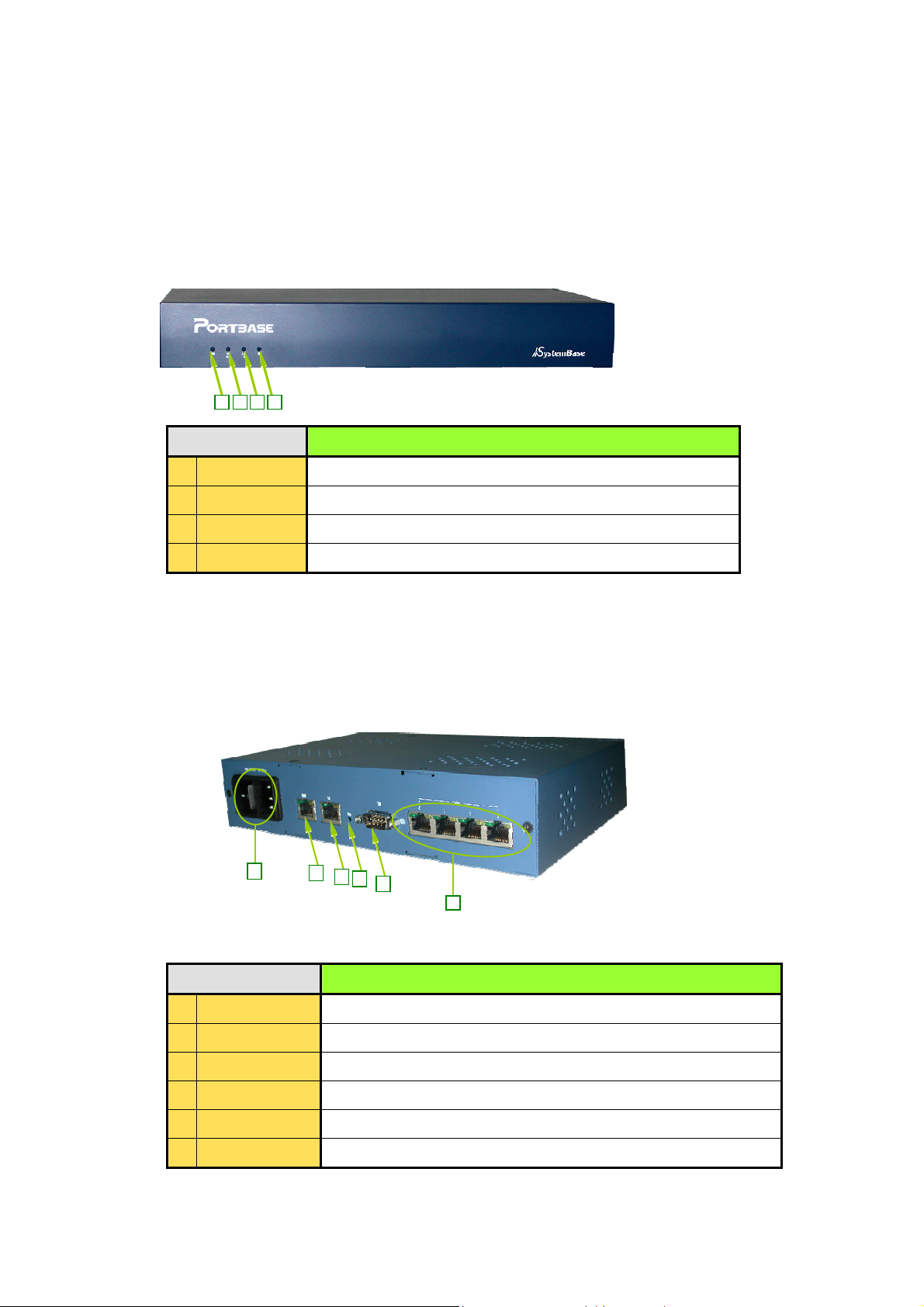
2. Structure
1
Model 2040:
Front View
2 4 3
LED Description
1 PWR
2 RDY
3 WAN
4 LAN Not used
Rear View
Turns red on power on
Turns green on normal run(Flickers at fault)
Turns green with LAN port is connected
1
2
3
4
5
6
Description
1 POWER
2 WAN
3 LAN
4 RESET
5 CONSOLE
6 SERIAL
Socket to provide 100-220v AC, 50-60Hz power
10 Mbps Ethernet RJ-45
10 Mbps Ethernet RJ-45 (not used)
Hardware reset button
Serial port for environment configuration
RJ-45 type socket for serial ports (RS232/422/485)
5
Page 6
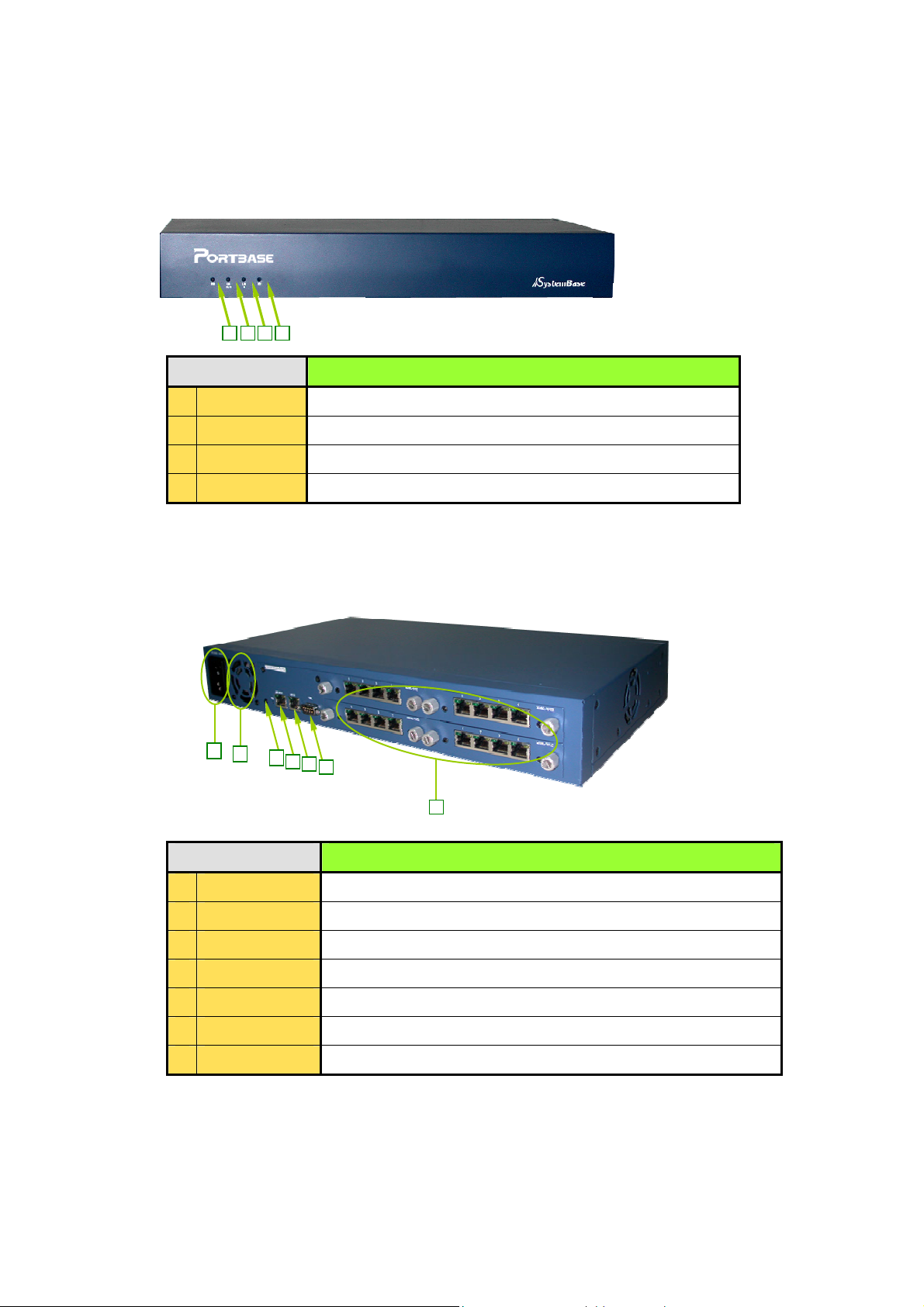
Model 2160/2161/2321:
1
1
Front View
2 4 3
LED Description
1 PWR
2 LAN10/100
Turns red on power on
Turns green when LAN10/100 port is connected
3 LAN10 Not used
4 RDY
Turns green if the firmware is ready (flickers at fault)
Rear View
2
3
4
5
6
7
Description
1 POWER
2 COOLER F AN
3 RESET
4 LAN10/100
5 LAN10
6 CONSOLE
7 SERIAL
Socket to provide 100-220v AC, 50-60Hz power
To prevent overheating
Hardware reset button
10/100 Mbps Ethernet RJ-45
10 Mbps Ethernet RJ-45 (not used)
Serial port for environment configuration
RJ-45 type socket for serial ports (RS232/422/485)
The above description conforms to both 2321 and 2161 models.
However, 2321 and 2161 have 32 and 16 serial ports respectively beside the
fixed serial modules.
6
Page 7

3. Features
It enables the access of the serial device thru network.
You can use the existing COMx/TTYx communication programs thru network
4. Specifications
Description
2040 2160 2161 2321
Serial Port
Weight
SDRAM
CPU
LAN 10/100 or
WAN
Size
Flash RAM
LAN 10 or LAN
Serial Port Type
Serial Port
Speed
Console Port
LED
Modem Signal
Line Control
4 (Fixed) 16 (Expandable) 16 (Fixed) 32 (Fixed)
1.3 kg 3.52 kg 2.59 kg 3.04 kg
32 M 64 M
32 Bit RISC Processor
10/100 Mbps Ethernet Port (Model 2040: not used)
439 * 234 * 63 mm (Model 2040: 240 * 157 * 50 mm)
4 MB
10 Mbps Ethernet Port (Model 2040 only)
RS232, RS422, RS485
Maximum 230.4 Kbps
9600 bps / RS232 / DB9
PWR, RDY, WAN, LAN
Controls all modem signal lines except RI
Overvoltage
Protection
Protocol
Environment
Setting
Management
Tool
Redirection
Power
All modem signal lines have surge protection.
Supports TCP, UDP, Telnet, ICMP, DHCP, TFTP, HTTP, PPP, SNMP
Console, Web
Portview, Web
Windows-based COM Port Redirection
Unix/Linux-based TTY Port Redirection
100 - 220 VAC (Free voltage)
7
Page 8
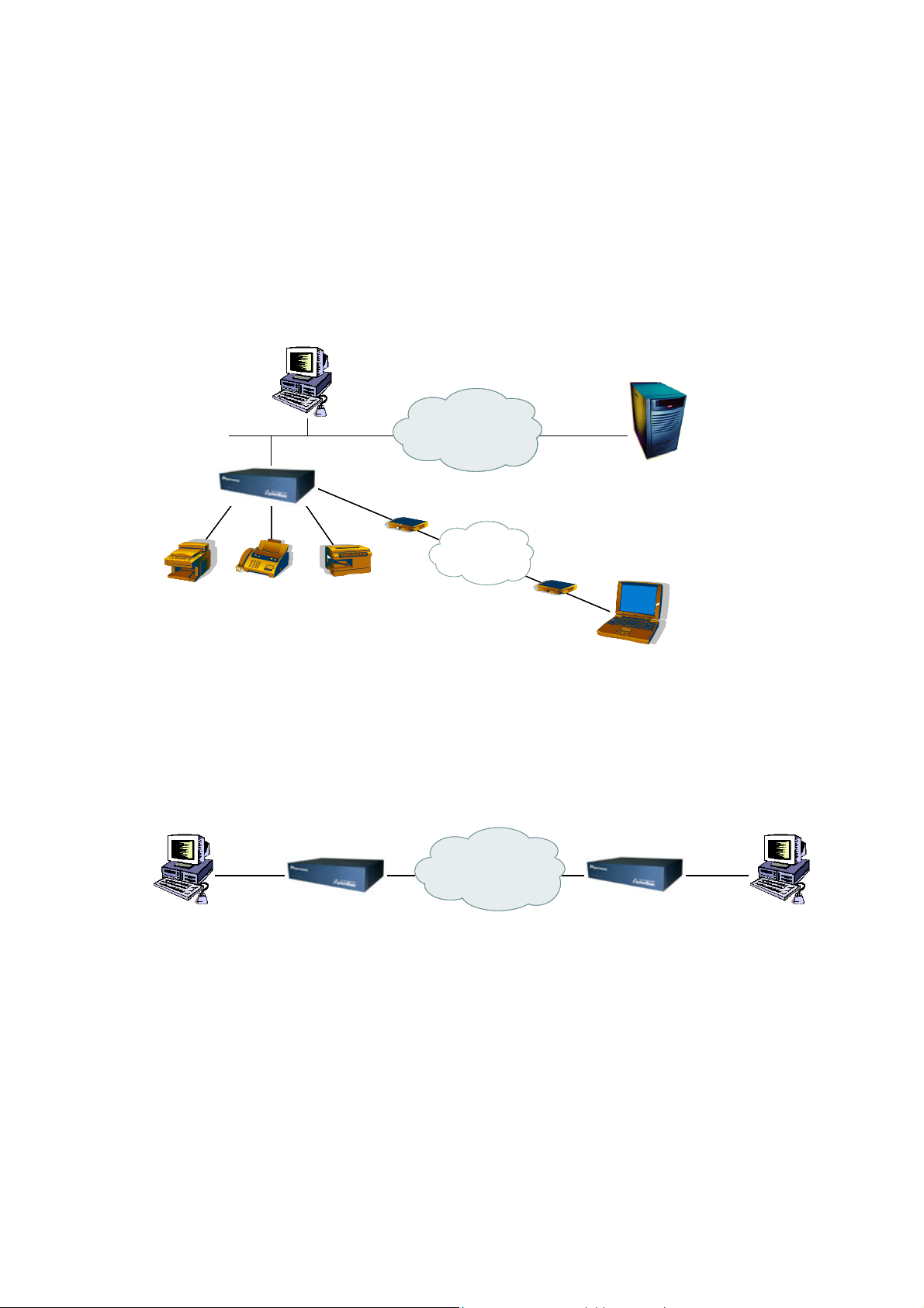
5. Applications
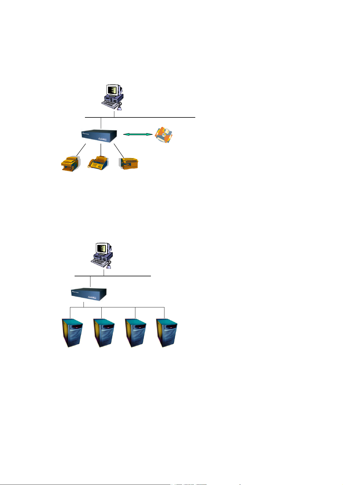
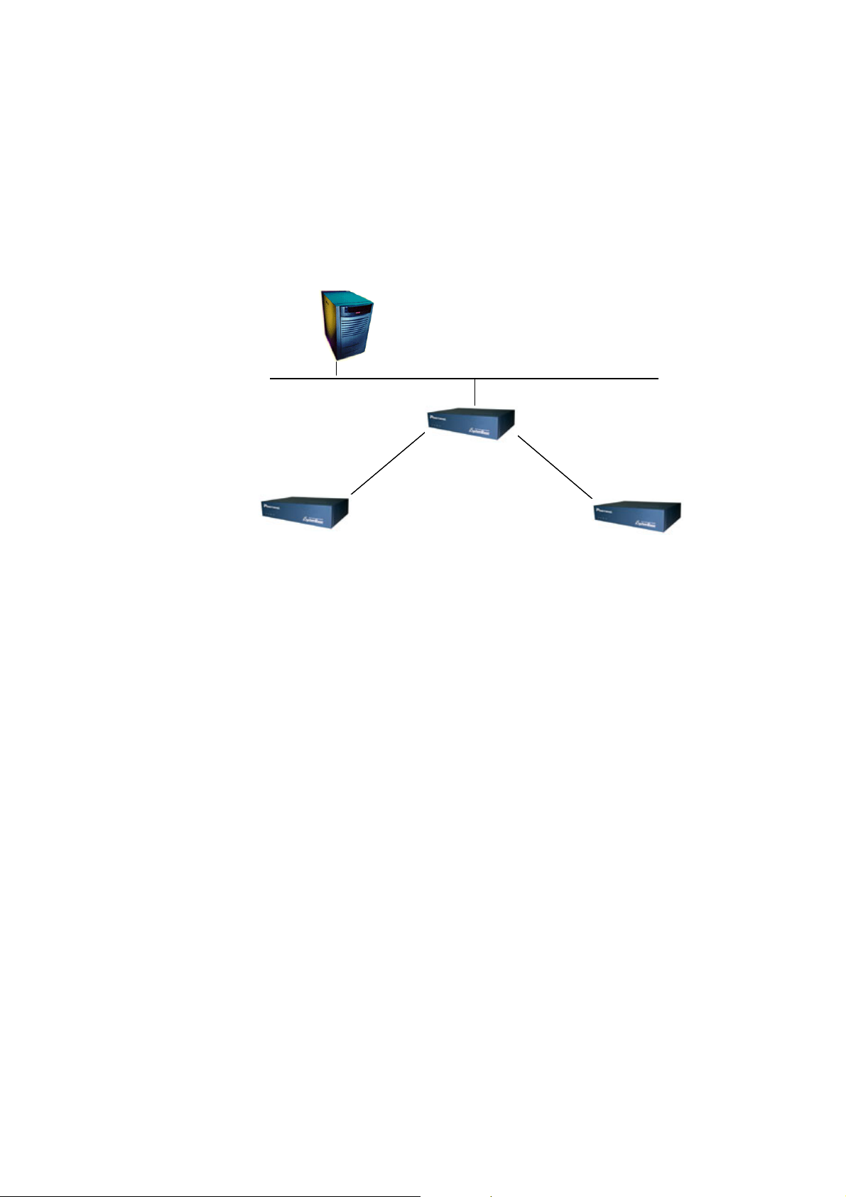
You can use the Portbase in various ways.
1) Network Serial Communication
This is the most common application of PortBase. By connecting a PC and a PortBase to a network,
you can use serial equipments connected to the Portbase from remote PCs.
2) Serial Communication Tunneling
You can use the network as if it is a serial cable from your PC.
LAN
LAN
Serial Devices
Serial Devices
Serial Devices
Serial Devices
PC
PC
PC
PC
Portbase
Portbase
Portbase
Internet
Internet
Internet
Internet
Internet
Modem
Modem
Modem
Modem
PSTN
PSTN
PSTN
PSTN
PSTN
Modem
Modem
Modem
Modem
Server
Server
Server
Server
PC
PC
PC
PC
Serial
Serial
PC
PC
Portbase Portbase
Portbase Portbase
Internet
Internet
Internet
8
Serial
Serial
PC
PC
Page 9

3) Serial Port Redirection
By exploiting redirection feature, serial ports of PortBase connected to the network can be used in
the PC as if they belong to the PC.
PC
LAN
LAN
4) Serial Link
COM1
COM1
PC
COM2
COM2
Portbase
Portbase
Serial Devices
Serial Devices
Internet
Internet
Internet
COM3
COM3
Portbase
Portbase
Portbase
Portbase
PC
PC
Serial Link, using network-connected Portbases, enables other Portbases not connected to the
network to be perceived as if they were connected to the network.
PC
PC
LAN
LAN
Portbase
Portbase
Modem
Modem
PSTN
PSTN
PSTN
Serial Devices
Serial Devices
Modem
Modem
Portbase
Portbase
9
Serial Devices
Serial Devices
Page 10
5) Adding Customized Features
Using Software Development Kit (SDK), you can add any function you want to PortBase. Please
refer to the Chapter 11 Portbase SDK for details.)
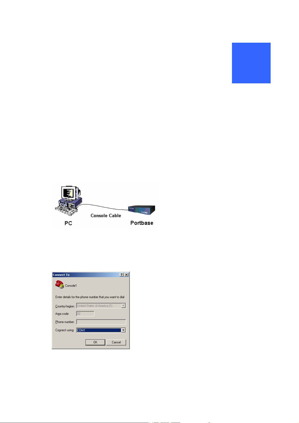
6) Console Server
Console server enables monitoring and controlling of multiple serial devices from one PC. These
serial devices can be connected through telnet application, and these may include server, router,
UPS, etc.
LAN
LAN
Portbase
Portbase
Serial Devices
Serial Devices
PC
PC
PC
PC
User Program
User Program
LAN
LAN
Portbase
Portbase
Servers
Servers
10
Page 11
2
Configuration
PortBase’s IP address is initially set to a default address, so it has to be reconfigured appropriately before
the first use. You can set the IP address and other operation parameters with Web browser or telnet from
PC, using the LAN, serial, or console port.
1. Setting address thru serial port
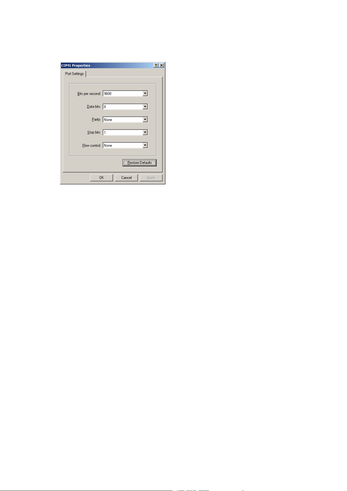
1) Connect the Console cable (DB9 to DB9) provided into COM port on the rear panel of Portbase.
2) Run the terminal emulator on the PC. This document describes with “hyperterminal” which is the
standard emulator of Windows.
Open COM port of the PC connected with Portbase.
11
Page 12
3) Set the COM port to 9600 bps, none parity, 8 data bit, and 1 stop bit.
4) Turn on the Portbase (By connecting the power line of Portbase to power).
5) Set the Portbase IP Address.
set ip User IP Address
6) Set the Subnet Mask (Default: 255.255.255.0) .
set mask User Net Mask Address
7) Set the Gateway IP Address(Default: 203.211.173.1) .
set gateway User Gateway Address
8) To confirm the over all setting values, use the command below.
set view
9) To write the Flash memory after altering, use the command below.
set save
10) After the environment settings are applied, you should restart the system
reboot
.
To remember the IP setting, write it down on the sticker below the Portbase
12
Page 13
2. Setting network with LAN port
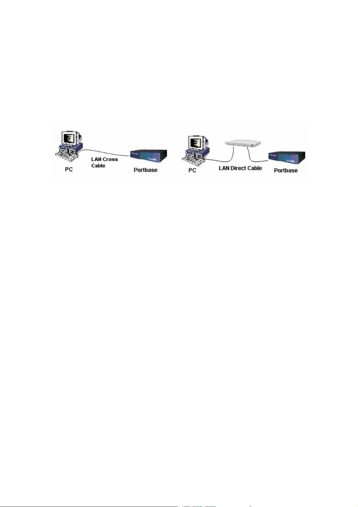
1) Connect the PC and Portbase to the network.
There are two ways to connect Portbase to the network : Direct connection with PC and connection
through HUB. (Connection port that can be used is either LAN 10/100 or WAN port of Portbase)
Direct connection with PC Connection through HUB
2) Set the PC IP address among the appropriate range of Portbase IP address.
(The factory default Portbase IP address is “192.168.1.72”.)
3) Run the web browser on the PC Windows and enter the IP address of Portbase in the address field.
(The factory default Portbase IP address is “192.168.1.72”.)
4) Configuration via web browser is discussed in Chapter 4 Configuration via Web
13
Page 14

3
Configuration via Serial Port
In order to configure the environment in details, you have to connect the serial port of the PC to that of
Portbase.
To do a detailed setup, use commands as follows.
1) Configure the Line Type.
Portbase provides 3 line types as follows.
IP Type Configuration:
DHCP Type Configuration:
PPPoE Type Configuration:
2) Configure the Portbase IP Address.
set ip
(Applicable only when the Line Type is IP.)
3) Configure the Subnet Mask. (Default: 255.255.255.0)
set mask
(Applicable only when the Line Type is IP.)
4) Configure the Gateway IP Address.
set gateway
(Applicable only when the Line Type is IP.)
5) Configure the PPPoE user name.
IP_ address
Net_Mask_Address
Gateway_Address
set line
set line
set line
IP
DHCP
PPPoE
set username
(Applicable only when the Line Type is PPPoE.)
6) Configure the PPPoE user password.
set userpass
(Applicable only if the Line Type is PPPoE.)
username
password
14
Page 15

7) Configure the Portbase alias name: up to 32 characters (Default: None)
set name
8) Configure the Portbase group name: up to 32 characters (Default: None)
set group
9) Configure the Portbase location name: up to 32 characters (Default: None)
set location location
10) Configure the NMS IP Address : (Default: 0.0.0.0)
set nms
(For more details, refer to PortView manual.)
11) Configure the password: up to 8 characters (Default: 9999)
set password
12) To confirm the configuration set, use command as follows
alias_name
group_name
_name
PortView_server_address
password
set view
13) After completion of configurations, you should
If you made any changes on configuration, you must execute the save command.
save the configurations you applied.
set save
14) After changing the configuration, you should reboot the system.
reboot
15) Write the IP address assigned on the sticker at the bottom side of the Portbase. to remember.
15
Page 16
Configuration via Web
4
Each Portbase has its own web page in it, and helps you set the operational configuration appropriate to
each individual environment.
The web page for the configuration consists of:
Network Configuration
Serial port Setting
Firmware Update
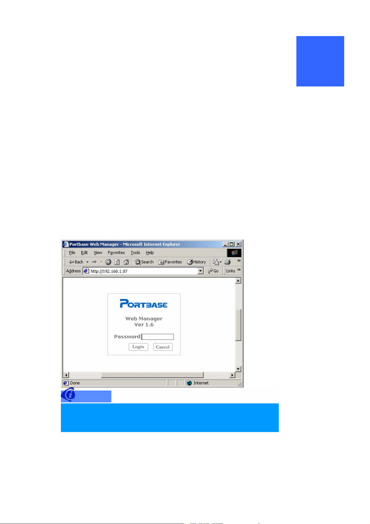
1. Getting started
1) Set IP address of Portbase first, if you have not set it yet (See Chapter 2 Configuration.)
2) Enter the Web page of Portbase thru browser by IP address.
3) Enter the password, If the initial window as shown below appears.
Password is initially set to '9999'.
Please, try to connect thru serial port, if you forget password.
4) Click “LOGIN” and start Operational Environment Setting.
16
Page 17
Network Setting : Set networking operational environment
Port Setting : Set serial port operational environment.
Save & Restart : Save settings and starting for normal runs.
Factory Default : Reset all Portbase settings to factory default values.
Firmware Updating : Update Portbase firmware.
About Portbase : shows product information and contact numbers.
17
Page 18
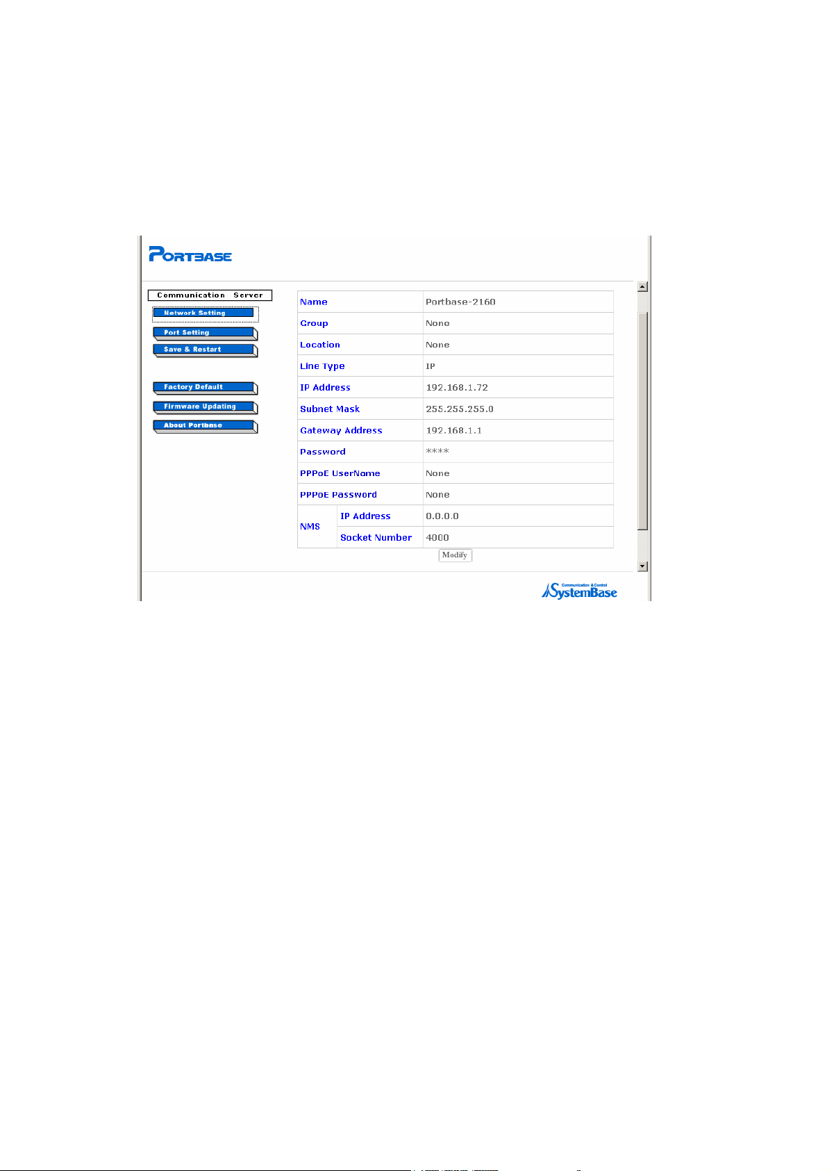
2. Network Setting
Perform IP address settings when you intend to change the Portbase IP address or password.
1) Click on “Network Setting” and the following window will appear.
2) Click on “Modify” and a window will appear to modify the configuration.
Name
Name the Portbase for the ease of identification by user.
Up to 32 characters
Group
Assigns the group name for the Portbase.
Up to 32 characters
Location
Assigns the name where the Portbase is located.
Up to 32 characters
Line Type (Default: IP)
Select Network Line Type (IP, PPPoE, or DHCP).
IP Address
18
Page 19

Set the Portbase IP address for network access.
To configure the network through the Link function(cascaded configuration between Portbases)
of other Portbase, you should certainly set the address to ‘0.0.0.0’. (Only IP Line Type)
Subnet Mask (default:255.255.255.0)
Subnet Mask is determined according to the class of IP address.(Only for IP Line Type)
Gateway Address
A router’s IP address in the same LAN segment as the Portbase(Only for IP Line Type)
Password (default:9999)
Sets password to access the Portbase web page via the web browser.
PPPoE UserName (default: None)
Sets an Identification of PPPoE(Only for PPPoE Line Type)
PPPoE Password (default: None)
Sets a Password of PPPoE(Only for PPPoE Line Type)
NMS IP Address (default:0.0.0.0)
Sets an IP address to communicate with PC where the PortView software is installed.
(Refer to the ‘Portview Manual’ for details.)
NMS Socket Number (default:4000)
Type the socket number to communicate with PC where the PortView software is installed.
19
Page 20
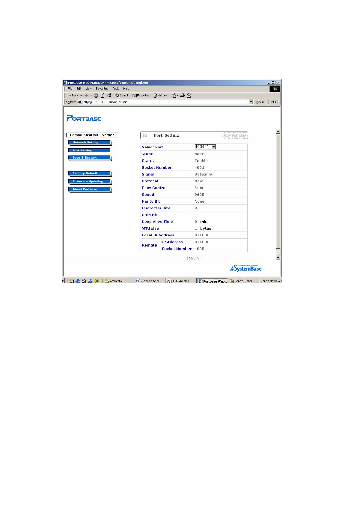
3. Serial port Setting
1) Click on “Port Setting” and the following window will appear
2) Click on “Modify” and the window for modification appears, then you can make new settings.
Select Port.
Port number to be set.
Choose “All Ports “ and all ports can be set to the same value.
Name
Give the port a name that is easily recognized by the users.
Maximum of 16 characters
Status (Default: enable)
Whether the port can be used or not. (enable, disable)
20
Page 21

Socket Number
The socket number assigned to the port.
Software uses this number for network communication.
Port 1 Socket 4001
Signal (Default: DataOnly)
Select the signal line that the serial port will provide and examine. (Modem, DataOnly)
If the Signal is set to Modem, all modem signals except RI are provided and examined for
communication.
If the Signal is set to DataOnly, communication is performed only with Txd, Rxd, Gnd lines.
Protocol (Default: COM)
J Passive
Portbase plays the role of socket server and enables serial equipment or PCs to directly
access the socket client. If the serial equipment or PC is successfully connected to the
socket client, data transmitting/receiving become possible.
J Active
When the serial equipment or PC is on standby for access as a socket server, Portbase
plays the role of socket client and tries to access the serial equipment or PC. If the
connection fails, Portbase will continuously try to access the serial equipment or PC until
they are successfully connected, thus enabling data transmitting/receiving between them.
J Mpassive
Portbase plays the role of socket server and enables serial equipment or PCs to directly
access the socket client and limits the number of outstanding connections in the socket's
listen queue to the number 5. If the serial equipment or PC is successfully connected to
the socket client, data transmitting/receiving become possible.
J Telnet
A general telnet client program. The program can access any server where the telnet
server is being operated.
J COM
COM is used for PC’s COM port expansion.
21
Page 22
J TTY
J Link
TTY is used for the Unix/ Linux’s TTY port expansion.
Link enables other Portbase to be connected to the network.
Portbase
Portbase
Portbase
J User
IP 192.168.1.1
IP 192.168.1.1
IP 192.168.1.1
Server
Server
LAN
LAN
LAN
Local IP 10.10.10.100
Local IP 10.10.10.100
Local IP 10.10.10.100
Local IP 10.10.10.100
Remote IP 10.10.10.201
Remote IP 10.10.10.201
Remote IP 10.10.10.201
Remote IP 10.10.10.201
IP 0.0.0.0 IP 0.0.0.0
IP 0.0.0.0 IP 0.0.0.0
IP 0.0.0.0 IP 0.0.0.0
Local IP 10.10.10.201
Local IP 10.10.10.201
Local IP 10.10.10.201
Local IP 10.10.10.201
Remote IP 10.10.10.100
Remote IP 10.10.10.100
Remote IP 10.10.10.100
Remote IP 10.10.10.100
Server
Portbase
Portbase
Portbase
IP 192.168.1.2
IP 192.168.1.2
IP 192.168.1.2
Local IP 10.10.10.100
Local IP 10.10.10.100
Local IP 10.10.10.100
Local IP 10.10.10.100
Remote IP 10.10.10.202
Remote IP 10.10.10.202
Remote IP 10.10.10.202
Remote IP 10.10.10.202
Local IP 10.10.10.202
Local IP 10.10.10.202
Local IP 10.10.10.202
Local IP 10.10.10.202
Remote IP 10.10.10.100
Remote IP 10.10.10.100
Remote IP 10.10.10.100
Remote IP 10.10.10.100
Use user program. You may register your own program as following steps
1) Write your program. (Refer to Chapter 11 Portbase SDK)
2) Compile this code by cross-complier and create object file.
3) Compress the object file to “user.zip” name.
Portbase
Portbase
Portbase
(You should be less than 250000 bytes the size of “user.zip” file.)
4) Upload to Portbase, using ftp program.
(Username: portbase, Default password: 9999)
5) Portbase will reboot automatically, After uploading at “/home/portbase” directory.
6) Set your program to configuration of Portbase, using a telnet or web.
<Telnet program>
% set port 1 protocol user
(Set your program to port number 1)
% set port 1 name user_program_name
(Set the name of user program to port number 1)
% reboot
(System will reboot.)
7) The demon of user program will carry out atomically.
22
Page 23

Flow Control (Default: None)
J A flow control protocol. You can set it to None, RTS/CTS, Xon/Xoff, Xoff.
Speed (Default: 9600 bps)
J Speed can be set to the communication speed range of 150 bps ~ 230.4 Kbps.
Parity Bit (Default: None)
J A parity check method. You can set it to None, Even, Odd.
Character Size (Default: 8)
J Number of bits constituting one byte. You can set it to 5,6,7,8.
Stop Bit (Default: 1)
J Number of Stop Bits. You can set it to 1, 2.
Keep Alive Time (Default: 0 sec)
J The port is logically connected to PC and if the given time has been passed since
receiving or sending last data, this will automatically disconnect the port from the PC. (0–
connection will be maintained)
MTU Size (Default: 1 byte)
J If there needs a certain volume of incoming data to be continuously received, you can
designate the MTU value.
Local IP Address
J The port’s virtual IP address when it is used as a channel for other Portbase connection.
The address is used in case of Link protocol.
Remote IP Address
J The opponent’s IP address. The address is used in case of Active-TCP; Telnet; Link
protocol.
Remote Socket Number
J The opponent’s socket or port number. The number is used in case of Active-TCP; Telnet;
Link protocol.
23
Page 24

4. Applying settings
After the operation environment setting is successfully completed, you should click on “Save &
Restart” to apply the new settings to Portbase.
5. Reset
To return the Portbase back to its initial settings, you can click on “Factory Default”.
Please be careful, because you will have return to the first configuration step after
using the Reset function.)
24
Page 25

6. Firmware Update
Firmware is the Operating System (OS) loaded in the Portbase flash memory.
You can download the latest firmware of Portbase from the SystemBase web site.
The steps to update the firmware are as follows.
1) Access the download page at SystemBase web site at
2XXX firmware file.
2) Access the Portbase web page via the browser.
3) Click on “Firmware Updating” and the following window for firmware updating will appear.
www.sysbas.com and download the pb-
25
Page 26
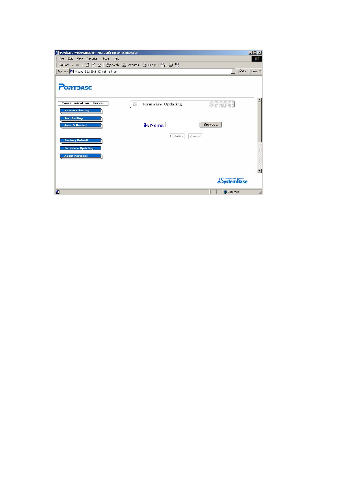
4) Click on “Browse” and find the firmware file location.
5) Click on “Updating” and the firmware will be automatically updated.
26
Page 27
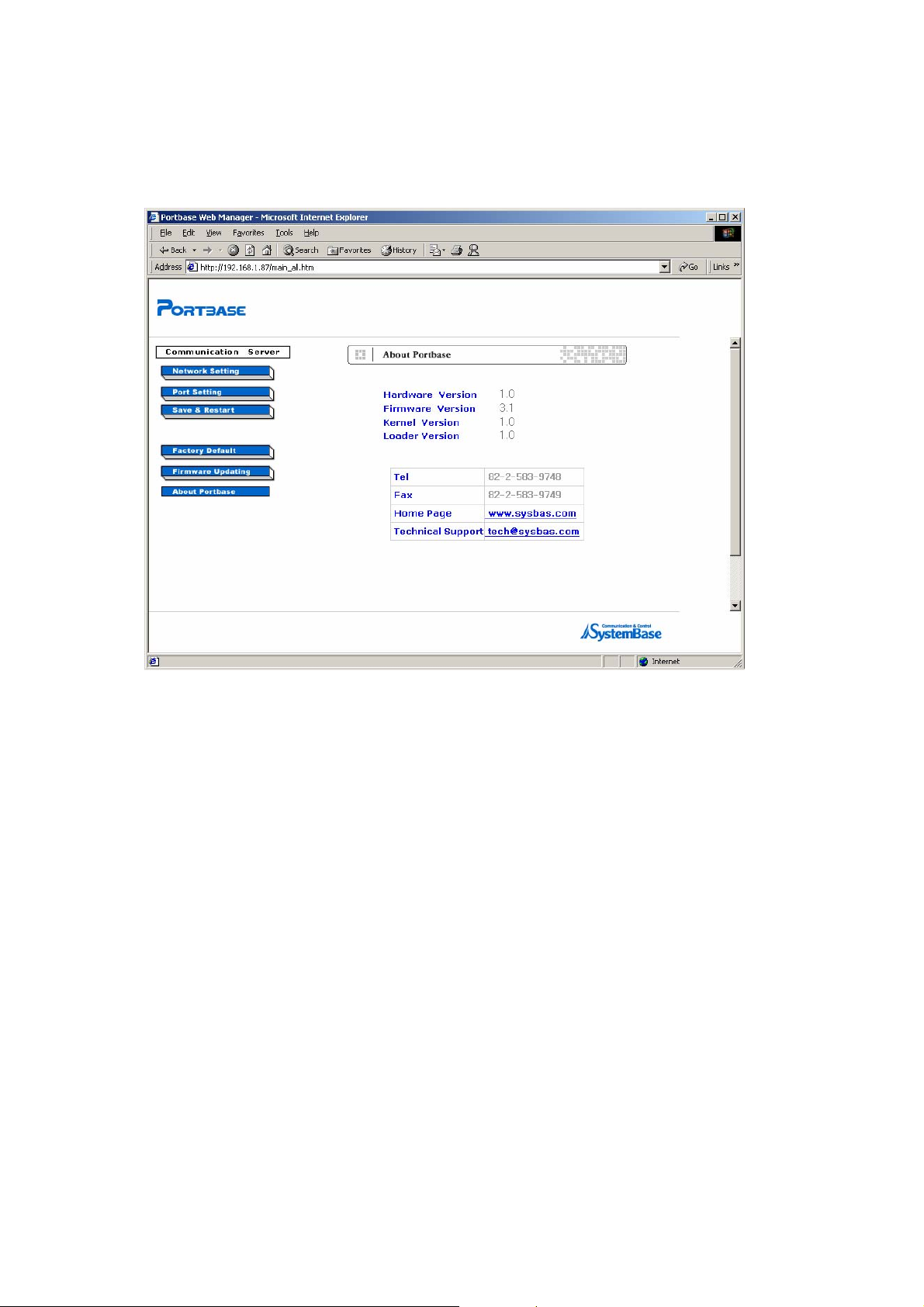
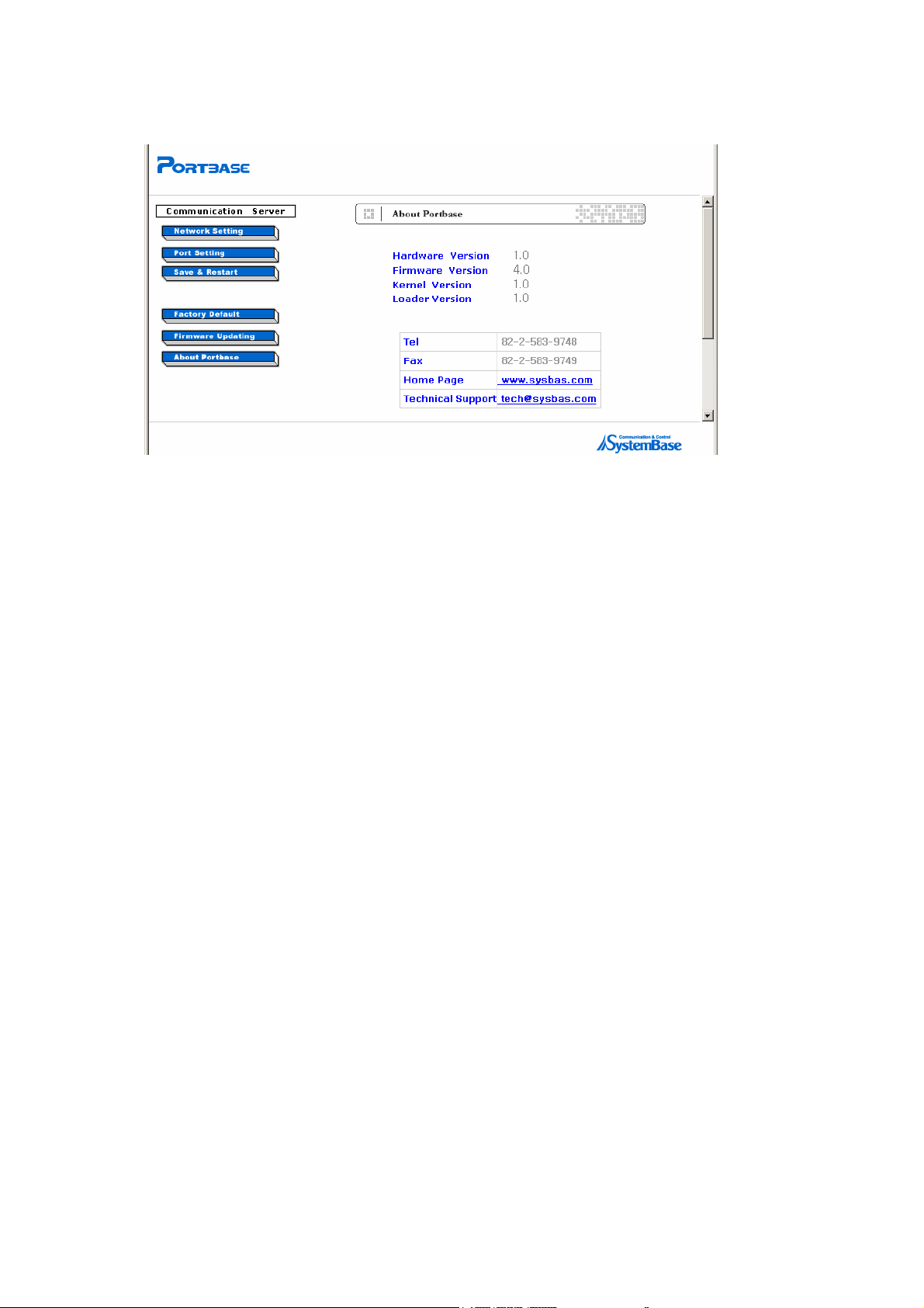
7. Portbase Information
Click on “About Portbase“ and you can see the Portbase information and contact numbers.
27
Page 28

5
Portbase Installation
1. Connecting Network
Have the Portbase and PC(or server) access the network
Connect the direct LAN cable to LAN1 port on the rear panel of Portbase, and to network(normally to
HUB) to do this
2. Connecting Serial Equipment
LAN
LAN
Connect the serial equipment to the Portbase using serial cable.
(Refer to Chapter 10 Cable Specifications)
Connecting the serial equipment Locally
PC
PC
Portbase
Portbase
LAN
LAN
Server
ServerServer
Portbase
Serial Devices
Serial Devices
Portbase
28
Page 29
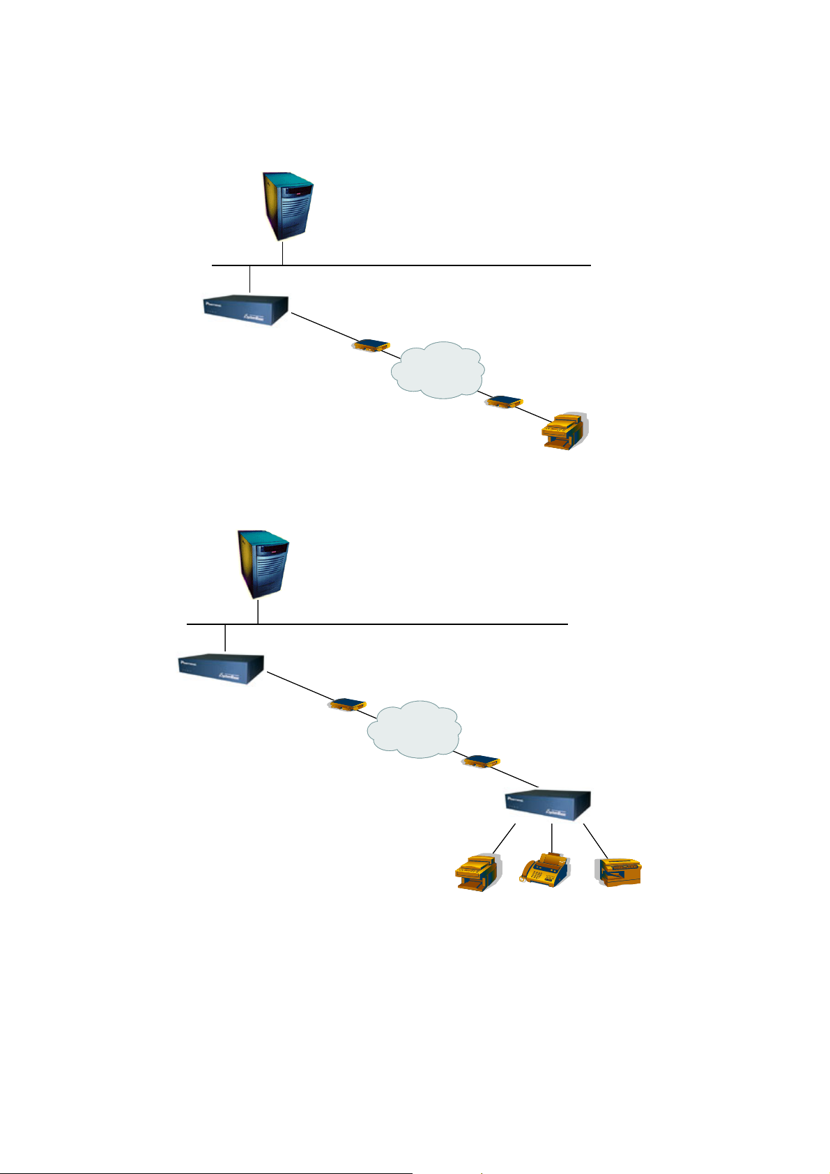
Connecting serial equipment remotely
LAN
LAN
Server
ServerServer
(Protocol: COM)
Portbase
Portbase
(Protocol: COM)
Modem
Modem
PSTN
PSTNPSTN
Connect the serial equipment through Link configuration
Server
LAN
LAN
ServerServer
Modem
Modem
Serial Device
Serial Device
Portbase
Portbase
Modem
Modem
PSTN
PSTNPSTN
Modem
Modem
Portbase
Portbase
Serial Devices
Serial Devices
29
Page 30

COM Port Redirection
1. Redirector Introduction
Redirector is a network COM port driver, enabling serial ports of Portbase to operate the same way as the
local COM ports of PC.
Upto 255 COM ports can be registered in one PC if Redirector is used.
1) Supported Hardware
Portbase 2010 / 2040 / 2160 / 2160 / 2161 / 2321
2) Supported Software
6
COM Port Redirector for Windows 98/ME
COM Port Redirector for Windows 2000/XP
3) System Requirements
PC system requirement for running Redirector is as follows.
CPU : Pentium 100 MHz or higher
Memory : 16 Mb or more
Operating System : Windows 98/ME/XP/2000/2003/NT
CD-ROM : Faster than 4X
Network : 10M Ethernet or higher
30
Page 31

2. Installing Redirector
Before installing Redirector, operation environment setting needs to be done for Portbase.
Refer to Chapter 2. Configuration if you want to configure operating environment.
1) Installing under Windows 98/ME
1) Insert the Portbase CD into the PC to install Redirector in.
2) Upon insertion, the following menu will be autorun. Select “Install Redirector”.
3) On the following screen, select “Windows 98/ME”. Then Redirector will be installed on the PC
automatically.
31
Page 32

4) When Redirector is run after installation is complete, Redirector Manager icon will appear in the
system tray.
32
Page 33

2) Installing under Windows 2000/XP
1) Insert the Portbase CD into the PC to install Redirector in.
2) Upon insertion, the following menu will be autorun. Select “Install Redirector”.
3) If you select “Install Redirector for Windows 2000/XP”, the Install Wizard for SystemBase
Redirector will appear on the screen automatically.
4) When the Install Wizard runs, shown in the next figure, click “Next”
If you are using Windows XP, warning on the Windows compatibility test might be displayed. Just
click “Continue” for installation.
33
Page 34

5) The screen shown above will be displayed. Select how many COM ports you’d like to install and
insert the IP address of Portbase that will be connected to. Finally, assign the socket number that
the first COM port will connect to. Then click “Next”.
Using the Install Wizard, upto 32 COM ports can be installed at once.
6) COM ports are installed to the system. The number of COM ports installed depends on the number
of ports you selected in the step (5).
If you are using Windows XP, the installation process is shown by the system tray icon.
34
Page 35

7) If you are using Windows XP, the wizard asks for the location of the driver while installing.
8) Follow the steps shown in figures. Then click “Next”.
9) Installation process will continue. If you are using Windows XP, warning may be displayed. In this
case, just click “Continue”.
35
Page 36

10) Click “Finish” to proceed installing the next port if there are any. Repeat this procedure until all the
ports are installed.
11) After the installation of the last port, the Installation Result window is displayed.
Installation process is completed when you click “Next” from the figure above.
The Installation Result window shows the list of COM ports that are installed and the IP address
and socket number of Portbase.
36
Page 37

J If you want to install additional COM ports, you need to run the installation wizard again, shown in
step 4). When the wizard detects existing ports installed, the following screen shows up.
Choose “Add Ports” if you want to install additional COM ports.
The remaining steps are identical to installing new ports.
37
Page 38

3. Using Redirector
With COM Port Redirector, you can use serial ports in Portbase from the remote site as if they belong to
your own PC. These ports operate just like COMx console ports in your PC.
The following figure describes how the communication between the PC with Redirector installed and the
serial devices attached to Portbase is done via network.
COM3 COM4
COM3 COM4
COM3 COM4
PC
PC
PC
LAN
LAN
LAN
Serial Device
Serial Device
Serial Device
Portbase
Portbase
Portbase
Serial Device
Serial Device
Serial Device
Portbase
Portbase
Portbase
38
Page 39

1) Using Redirector in Windows 98/ME
1) Configure Redirector
To run the Redirector Manager, double-click the Redirector Manager icon from the system tray, or
select Start Program SystemBase Portbase Redirector.
2) Register COM ports.
When you click “Add” from the main menu, general information about the COM ports to install
will be displayed
Enter the COM Port ID(COMx), IP address of Portbase, Port Number (1 to the maximum
number of ports), and the description or the port name (16 bytes maximum).
Multiple IP addresses and port numbers can be registered to one COM port.
39
Page 40

When all the information is provided, you can click “OK” to add a new port, shown in the next
figure.
Nothing is displayed under the Status tab if the Redirector service did not start for each port.
By repeating the steps shown above, multiple serial ports can be registered as a candidate for
connecting to one COM port.
If you like to remove a port, click on the port to remove and click “Remove”.
3) Starting / Stopping the Service
From the Redirector Manager main screen, select ports to start Redirector service.
Selected ports will be highlighted.
Click one more time to unselect any selected port.
Only one serial port for each COM port can be selected.
After selecting all the ports desired, click “Start” to activate the Redirector service.
Certain information will be displayed for Status tab once the service is activated for ports.
The list of conditions to be displayed for Status tab is as follows.
Ready : Virtual serial port is set by Redirector on the PC, and is waiting.
Connecting : The connection between Portbase and the virtual serial port set by
Redirector on the PC is on processing.
40
Page 41

Connected : The connection between Portbase and the virtual serial port set by
Redirector on the PC is established.
Disconnected : The connection between Portbase and the serial port in the PC is lost.
COM Opened : Portbase doesn’t operate even though the serial port in the PC is open.
Reconnecting : The virtual serial port set by Redirector on the PC is reconnecting to
Portbase.
(If any kind of unexpected error causes disconnection, reconnection is
attempted to a certain port and a port number at constant intervals.)
Switching : Multiple IPs are assigned to one port and IP changes real-time.
Upon selecting a port and clicking “Stop”, the Redirector service for that port is terminated.
Once the service is terminated, Status tab for that port will be empty.
Information such as the COM port number, IP address and Port number is shown when the service
is performed. Once the service is terminated, these information automatically disappears from the
screen.
The service for one COM port can be started by either the “Start” button or the application program
which handles Redirector actions. Regardless of the service-activating source, it is always the last
action performed that achieves the higher priority.
If you click “Exit”, all the Redirector services for all ports are over, system tray icon disappears, and
Redirector quits.
If any COM port is on service when the “Exit” button is pressed, message box indicating that the
port is in use pops up and the service is not terminated.
If Redirector is restarted, the Redirector service may either be resumed automatically or not. This
is determined by the previous configuration (the Tray icon configuration).
41
Page 42

2) Using Redirector in Windows 2000/XP
1) If Redirector is not installed in your system, install Redirecor. (Refer to 2.Installing Redirector in this
chapter for more information)
2) If Redirector is installed in Windows 2000/XP, virtual driver is loaded to the system automatically
when the PC boots.
3) Now you can see that virtual Redirector Port is created under “Ports (COM and LPT)” in Device
Manager. (To open the Device Manager, select Start-> Setting Control Panel System
Hardware Device Manager)
4) Right-click on the “SystemBase Redirector” under “Multi-Port Serial Adapters” and select
“Properties”. (Multi-Port Serial Adapters SystemBase Redirector)
42
Page 43

5) If you like to change the IP address and the socket number of Portbase assigned to the virtual COM
port, click “Edit”.
6) Enter the IP address, socket number (4001 to 40xx) and the port name (32 bytes maximum) that
you like to edit. Click “OK” to apply new settings.
43
Page 44

7) If you want to enable data encryption for your communication, check “Data Encryption”.
(Encryption mechanism used in this option is SEED, a 128-bit symmetric key type block encryption
algorithm.)
8) If the user application opens the virtual COM port registered in the system, the Redirector service
starts. The connection is established using the IP address and the socket number designated for
Portbase.
9) If the user application closes the COM port, the connection with Portbase is lost and the Redirector
service is terminated.
44
Page 45

4. Uninstalling Redirector under Windows 2000/XP
To uninstall Redirector under Windows 2000/XP environment, follow the steps shown below.
1) Refer to the section for installing Redirector to run the Install Wizard for SystemBase Redirector.
You should see the same screen as shown below.
2) Click “Next”.
3) Select “Remove” from the menu, and click “Next”.
45
Page 46

4) Uninstallation is completed when you click “Finish”
46
Page 47

7
TT Y Port Redirection
Using the RTCP program, you can use the Portbase serial ports as if they were the serial port dev/ttyXX of
your PC.
The following figure shows the serial devices connected to a network through virtual device ttyxx that is
created by the RTCP program in a Unix environment.
PC
PC
LAN
LAN
LAN
PC
TTYS1
TTYS1
TTYS1
TTYS0
TTYS0
TTYS0
Serial Devices
Serial Devices
Serial Devices
Portbase
Portbase
47
Page 48

1. Installation on Linux/Unix
Only Redirector software is provided for Linux/Unix environment.
Installation steps of Redirector for Linux/Unix are as follows:
1) Insert the Portbase CD.
2) Create a ‘RTCP’ directory under the Linux/Unix client’s /etc directory.
mkdir /etc/rtcp
3) Change to ‘etc/rtcp’ directory.
cd /etc/rtcp
4) Copy the ‘rtcp’ program to /etc.rtcp directory, then uncompress it.
tar xvf rtcp.tar
The following files are generated.
makefile : The execution file creator
rtcp.c : ‘rtcp’ program source code
rtcp.conf : Configuration file used to connect each Portbase’s port and socket.
rtcp.doc : rtcp Help
util.c, rtcp.h : Reference header file
5) Modify ‘Makefile’ compiling options according to your Linux/Unix system and versions.
Following Unix OS are supported.
SVR4, ESIX 3.2, Interactive 386/ix, CLIX, RS/6000, SCOUNIX,
HP-UX, SunOS, DEC, Linux
6) Generate the execution file by compiling the ‘rtcp’ source.
make
If compiling errors occur, verify if the ‘makefile’ has the exact definition for your O/S version.
When compiling again, remove the previously generated ‘obj’ file first.
7) The installation is completed with the execution of the ‘/etc/rtcp/rtcp’ generated..
8) If the ‘rtcp’ program needs to be removed from your PC, use the following command;.
rm –rf /etc/rtcp
48
Page 49

2. RTCP Port Addition
1) Add a Portbase to etc/hosts file.
vi /etc/hosts
Type “203.240.173.130” for Portbase IP address and “Portbase” for name, respectively.
2) Modify the rtcp.conf environment file.
vi /etc/rtcp/rtcp.conf
#Host_name equipment_name socket_number
#-----------------------------------------------------------------------------------
Portbase /dev/ttys0 4001
Portbase /dev/ttys1 4002
……… …………… ……
Host_name : Portbase name registered in /etc/hosts file
Equipment_name : Device name to be accessed in the user program
Socket_number : Socket number to access the Portbase serial ports.
3. Starting RTCP
Run the rtcp execution file as the background.
./rtcp&
ttys0 means the Portbase no.1 serial port and ttys1, no. 2 serial port.
4. Finishing RTCP
Run the “ps -ef” command and obtain the process number of the previously executed rtcp, and then
“kill process number” to stop the rtcp.
49
Page 50

8
Management with Portview
1. Portview Introduction
Portview is the program that enables you to monitor the Portbase communication sutatus in real time.
Portview displays the data input/output through each serial port as well as the communication status of
Portbase from remote PCs under the Windows environment.
1) Supported Hardware
This program supports all of Portbase 2xxx family products.
2) Supported Software
Install.exe (Portview installation application)
Portview.exe (Portview application)
Uninstall.exe (Portview uninstallation application)
3) System Requirements
PC system requirement for running Redirector is as follows.
CPU : Pentium 100 MHz or higher
Memory : 16 Mb or more
Operating System : Windows 95/98/ME/XP/2000
CD-ROM : Faster than 4X
Network : 10M Ethernet or higher
50
Page 51

2. Installing Portview
1) Installation
1) Insert the Portbase setup CD to the CD-ROM drive.
2) Run Setup.exe. (The program is started automatically if you insert the CD.)
3) Click on “Install” when the following installer opens up.
51
Page 52

4) As shown above, the program will be registered in the Program Group under ‘SystemBase
Portbase’.
5) To run the program, click on ‘Start’ ‘Program’ ‘SystemBase Portbase’ ‘Portview’.
52
Page 53

3. Using Portview
1) Portbase Setting
1) Type the Portbase IP address in the address windows to access the Portbase web site via the
web browser.
2) Enter the password of Portbase when the following window pops up.
3) Select ‘Network Setting’ from the menu to get the following screen showing.
53
Page 54

4) Click ‘Modify’ on the bottom of the screen. From the configuration screen that shows up, enter the
correct NMS IP address and click ‘OK’.
5) Click on “Save & Restart” to apply the new setting to Portbase.
(Refer to Chapter 2. Configuration for details.)
54
Page 55

2) Environment Setting
Password Setting
In order to prevent unauthorized access to Portview, click on ‘Settings’ ‘Password Setting’ from the
menubar.
Mark “Use Password” box and enter the password, and click on “OK”. Afterward, the password window
will appear to execute the the Portview.
Directory Setting
You can set the default directory to save the Portbase log file and the Datascope capture file.
55
Page 56

Communication Setting
Select whether Portview should keep displaying Portbase after it is disconnected, and set the external
connection port.
① If you select ‘Remove nodes automatically, if connections are failed’, the Portbase information
disappears as the Portbases are disconnected.
② Select ‘Resume Datascope, if failed connections are restored’ from communication options menu
bar if you want to set Datascope to be automatically executed when the failed Portbases are
reconnected. At this time, to automatically display incoming/outgoing data to/from each Portbase
port in real time, select ‘Resume PortManagement, if failed connections are restored’ as well.
(Both options are available at the same time)
56
Page 57

③ Type the socket number for Portbase connection. The default port number is 4000.
Datascope Screen Setting
You can change settings of the data input/output monitoring screen.
57
Page 58

3) Overall Portbase Management
You can manage all the Portbases connected to Portview.
The Portbases with different group names are displayed as different groups.
To close the group tree screen, click on
from the toolbar.
58
Page 59

Click on
to display Portbases of a group.
To display icon screen of a Portbase, click on
.
Because you selected sysbas, the tile becomes “Portview – [sysbas]”.
59
Page 60

In order to display detailed information of a Portbase, click on
Detailed information of Portbase is as below.
Name : Portbase name
Location : Portbase location
IP Address : Portbase IP address
MAC Address : Portbase MAC address
Starting Time : Portbase starting time
.
Model : Portbase model
Active Ports : The number of active ports
To return to the Portbase icon screen, click on .
To update the disconnected equipment information, click on ‘View’->’Refresh Group Tree’ from the
menu.
Configuration Setting
You can set configuration (name, location, group, IP, mask, gateway and etc.) of Portbase using web
and telnet.
(Refer to Chapter 3 Configuration via Serial Port and Chapter 4 Configuration via Web.)
To open web or telnet screen of a Portbase server, select the Portbase on the icon screen or the list
screen, and select ‘Config’ ‘Web Configurator’ or ‘Telnet from the menu’. (You can select Web or
Telnet only after you select a Portbase.)
(Selecting Telnet)
60
Page 61

4) Detailed Portbase Management
Portbase View
Port View screen:
1) Displays data on each Portbase’s port..
2) Displays errors on each Portbase’s port.
3) Displays environment configuration for each Portbase’s port.
① Starting
To run Portbase View, double-click on an equipment on the Group List View or the Portbase List
View.
<Initial Portbase View Screen>
61
Page 62

② Statistics
You can display input/.output data si nd errors of all ports of the equipment being monitored.
To see this
screen, click on from the toolbar.
The Ststistics screen is the same as th itial screen.
zes a
e in
<Statistics Screen>
Port : Displays port status.
: The port is a
: The port is available but no
: The port is unavailable. (Gray)
TxBytes : se port
The number of output data bytes through the Portba
ctive (Green)
t active (Red)
RxBytes : The number of input data bytes through the Portbase port
Rx Parity : The number of parity errors during data reading
Rx Framing : The number of framing errors during data reading
Rx Overrun : The number of overrun errors during data reading
62
Page 63

③ Settings
You can display settings of all ports.
Click on from the toolbar.
<Settings Screen>
Port : Port number and status of a Portbase
: The port is active (Green)
: The port is available but not active (Red)
: The port is unavailable. (Grey)
Name : Port name of the Portbase
Type : Port type of the Portbase (RS232, RS422, RS485)
Protocol : Protocol of the Portbase
(Passive, Active, Telnet, Com, Tty, Link)
Speed : Baud rate of the Portbase port (150, 300, 600, 1200, 2400, 4800,
9600, 19200, 38400, 57600, 115200, 230400)
Length : The number of bits indicating a character (5, 6, 7, 8)
Parity Error detection method of making the number of ‘1’s in a bit string to
be odd or even by adding a test bit to the given data bit string. (None,
Odd, Even)
Stop The bits added to indicate that a character ends (1, 2)
63
Page 64

④ Log file saving
You can make log files for port status and execution of program in Portbase. On the Portbase View
window, click on to display the log start message. The port operation status is recorded
on the log. In order to save the log file, click on
<Log Start Message>
When saving a log file, enter the file name and click on “Save” .
<Log Window>
64
Page 65

⑤ Log File
A log file is configured as below.
<Initial System Configuration>
Initial system setting
The red dotted part on the above screen. It contains the default settings.
Port setting
The below “Port Configuration” part.
The port status at the time of log start.
It has the same items of the “Settings” window of Portbase View.
<Demon Log Screen>
Demon record
Records start and end date, time, port and status of the Demon of each port.
Date : Year/Month/Date
Time : Hour:Min:Sec
65
Page 66

Port : The port where the Demon event has occurred
Demon : Type of Demon
Status : Demon starts - Started
Demon ends - Terminated
Connection error and reconnection
<Connection End Message and Reconnection Message>
The red dotted part shows the disconnecton time and indicates that all the programs are
terminated.
The reconnection time and settings are displayed when the connection is restored. (Status at
reconnection is Disable.)
66
Page 67

Data Scope View
Datascope window:
1) Displays input/output data on a port in ASCII.
2) Displays input/output data on a port in HEX.
3) Saves input/output data on a port.
① Starting data scope view
Select the port you want to see data scope of in the Portbase View window and click on
. Or, double-click on the port.
<Data Scope Window>
Toolbar
Open : Read the data scope file in “.cap”, and display it on a new
window.
Start : Start data scope of the port. The button remains pressed once it
is started.
Stop : Activated while data scope is running. Click this button to stop
data scope.
Erase : Initialize the window.
Capture Start : Write the data scope content on a file. If you click this button the
“Capturing” window is displayed.
Capture Stop : End writing data scope content, and save the file.
67
Page 68

Hexa Code Display the data scope content in Hexa code. If the button
remains pressed, ASCII data is changed into two-digit Hexa
code.
Back Close the window. (If Capture is active, the file saving window is
displayed.)
Data View
Input/output data on the port is displayed. If the data type is ASCII, the data is displayed as
they are. If you select HEX, they are displayed in hexadecimal. Use scroll bar to see the rest
of the data.
<Data View Window>
68
Page 69

② Operation
Data Scope Starting
If you click on and the remote Tx/Rx data is displayed on the screen.
Tx data is displayed on the upper line and Rx data is displayed on the lower line. The
<Data Scope - Ascii>
function measures buffering status near the data exchange time to arrange the data. To stop
the data scope function, click on
File Saving
If you click on “Capture Start”, the “Capturing” message is displayed and saved. (The Capture
Start button is pressed down while the message is saved on a file.) Click on “Capture Stop”.
The default file name is “pyymmddhhmm.cap”, and each two digit number indicates
year/month/date/hour/minute.
<Saving Data Scope File>
69
Page 70

To open a saved file, click on and select a file. The data is displayed on a new
window.
Data in Hexa code
In order to view data in hexadecimal format on Data View, click on Use scroll bar
to see the rest of the data.
<Data Scope - Hex>
70
Page 71

4. Uninstalling Portview
Click on ‘Start’ ‘Programs’ ‘SystemBase Portbase’ ‘Uninstall’.
71
Page 72

9
SNMP
SNMP(Simple Network Management Protocol) is used by the administrator (SNMP Manager) to monitor
and control the operation status of TCP/IP-based network devices (SNMP Agents) from the remote site.
To establish communication using SNMP, MIB (Management Information Base) between the Manager
and the Agent is necessary.
Portbase supports SNMP MIB-I and II standards.
MIB provided by Portbase (working as an SNMP Agent) is as follows.
MIB-II (RFC 1213) : System, Interface, Address Translation, IP, ICMP, TCP, and UDP
MIB-I (RFC 1317) : Serial Interface
Portbase status information is managed by the SNMP Manager, using Get/Set messages stored in MIB.
MIB of Portbase to be registered for the SNMP Manager is stored under the folder ‘SNMP’ in the Portbase
CD.
.
The following functions can be performed with the SNMP applied.
Network Architecture Management
Achieving a map of network hosts is possible, which implies the network architecture.
Performance Management
Many kinds of statistics that are essential to performance analysis can be achieved. These include
network usage amount, error count, performance speed, and response time.
72
Page 73

Device Management
Error history for each serial port, such as framing error, overrun error, parity error, etc. can be
identified. Also, signal line information (DCD, RTS/CTS and DTR/DSR) can be configured and
confirmed.
73
Page 74

Cable Specifications
1. Console Cable
10
74
Page 75

2. RS232 Serial Cable
3. RS232 Mode m Cable
75
Page 76

4. RS422 Serial Cable
5. RS485 Serial Cable
76
Page 77

6. Direct LAN Cable
7. Cross LAN Cable
77
Page 78

8. LoopBack Connector
The loopback connector can be used to verify if the Portbase hardware is ok by performing an
external loopback test. The loopback is plugged in the Portbase’s RJ45 serial port to test that the
Portbase serial port operates normally.
The following is the Loopback Connector Wire Diagram.
RS232 Loopback Connector RS422 Loopback Connector
78
Page 79

11
Portbase SDK
The Portbase SDK (Software Development Kit) is designed for custom application development on
Portbase.
1. Development Environment
CPU : Pentium 300 MHz or higher
Operating System : Unix or Linux
Device : Portbase (2xxx Series)
Compiler : Cross Compiler
(Link :
http://www.borg.umn.edu/~grant/Linux/cross.html )
2. List of Functions
U_open_port
Description This function opens the serial port whose port number is the port_no.
(Related device : 2040 / 2160 / 2161 / 2320)
Synopsis int U_poen_port (int port_no)
Parameters port_no : Serial port number (1 ~ 32)
Returns 1 ~ n : File descriptor if successful.
-1 : Otherwise
Serial Port Open
79
Page 80

U_open_port_2010
2010 Serial Port Open
Description This function opens the serial port whose port number is 1.
(Related Device : only 2010)
Synopsis int U_open_port_2010
Parameters
Returns 1 ~ n : File descriptor if successful.
-1 : Otherwise
U_init_port
Initialize Serial Port
Description This function sets the parameters associated with the terminal referred to by
the open file descriptor fd (an open file descriptor associated with a serial)
from speed, lcr, and flow.
Synopsis void U_init_port (int fd, int speed, char lcr, char flow)
Parameters
fd
: Serial file descriptor
speed : Setting Bauds
0 = 150 6 = 9600
1 = 300 7 = 19200
2 = 600 8 = 38400
3 = 1200 9 = 57600
4 = 2400 10 = 115200
5 = 4800 11 = 230400
Lcr : Setting Standard LSR Register
XXXXX
XXX
Data Bits : 0x00 = 5, 0x01 = 6, 0x02 = 7, 0x03 = 8
Stop Bits : 0x00 = 1, 0x04 = 2
Parity Bits : 0x00 = None, 0x08 = Odd, 0x18 = Even
flow : Setting Flow Control
0 = None, 1 = Xon/Xoff, 2 = RTS/CTS
80
Page 81

U_read_port
Read Serial Data
Description This function reads a number of bytes (less than or equal to buff_size) from a
specified file descriptor and places them in buff.
Synopsis int U_read_port (int fd, char *buff, int buff_size, int mtu_size)
Parameters fd : Serial file descriptor
buff : Pointer to buffer to receive bytes
buff_size : The maximum size of bytes to read into buffer
mtu_size : The maximum of a packet that can be transferred in one
frame over a network (maximum size : 1100)
Returns 0 : If end of file
n : The number of bytes read (between 1 and buff_size)
U_send_port
Send Serial Data
Description The function attempts to write the specified number of bytes from the
specified buffer to the specified serial file descriptor.
Synopsis int U_send_port (int fd, char *buff, int length)
Parameters fd : Serial file descriptor
buff : Pointer to buffer to write
length : Length of buffer
Returns n : The number of bytes sent
81
Page 82

U_check_dcd
Check Signal
Description The function detects a change of DCD signal in MSR (Modem status
register) of serial file descriptor.
Synopsis int U_check_dcd (int fd)
Parameters fd : Serial file descriptor
Returns 0 : If DCD signal status is OFF
1 : If DCD signal status is ON
U_check_type
Check Serial Type
Description The function detects a serial interface from serial file descriptor.
Synopsis int U_check_type (int fd)
Parameters fd : Serial file descriptor
Returns 0 : If serial interface is RS-232
1 : If serial interface is RS-422
2 : If serial interface is RS-485
U_connect
TCP Connect
Description This function is used to create a connection to a established connection-
based (stream) foreign association. It blocks, up to the specified timeout
interval.
Synopsis int U_connect (char *dest_ip, int dest_socket, int timeout)
Parameters dest_ip : Pointer to the peer IP address to connect
dest_socket : Socket port number
Timeout : A maximum interval to wait for the connection in second
Returns -1 : On failure
1~n : A descriptor that references the socket if successful
82
Page 83

U_listen
TCP Listen
Description This function enables connections to a socket. It also specified only one
unaccepted connection that can be pending at one time.
Synopsis int U_listen (int socket_no)
Parameters socket_no : Socket descriptor
Returns -1 : If the socket is invalid or unable to listen
1~n : A descriptor that references the socket if successful
U_accept
Wait TCP Accept
Description This function accepts a connection on a socket, and returns a new socket
created for the connection. It blocks, up to the specified sec and usec, until a
new socket generates.
Synopsis int U_accept (int fd, int sec, int usec)
Parameters fd : Socket descriptor
sec : A maximum interval to wait for the connection in second
usec : A maximum interval to wait for the connection in micro
second
Returns -1 : If the call fails
0 : Waiting but timeout
n : A socket descriptor if successful
83
Page 84

U_read_lan
Read TCP Socket
Description This function reads a number of bytes (less than or equal to buff_size) from a
specified file descriptor and places them in buff.
Synopsis int U_read_lan (int fd, char *buff, int buff_size)
Parameters fd : File descriptor from which to read
buff : Pointer to buffer to receive bytes
buff_size : The maximum size of bytes to read into buffer
Returns -1 : If the file descriptor does not exist
0 : If end of file
n : The number of bytes read (between 1 and buff_size)
U_get_mac
Read Mac Address
Description This function gets the MAC address.
Synopsis int U_get_mac (char *buff)
Parameters buff : Where to return MAC address
Returns -1 : If failed
0 : If successfully gets
U_msnow
Read Timer
Description This function returns the interval between turning Portbase on and current in
10 m second.
Synopsis int msnow ()
Parameters
Returns 0~n : Interval time in 10 m second
84
Page 85

3. Sample
1). User Active Program
All this program does is connect to the host you specify on the command line, and port you specify on
the command line. After connecting, sent data from TCP socket reads in serial port, and sent data from
serial file descriptor reads in connection-based (stream) socket.
/*---------------------------------------------------------------*/
struct SYS_INFO
/*---------------------------------------------------------------*/
{
unsigned char port_no; // 1 ~ 16
int speed; // 0=150 ~ 11=230400 BPS
char lcr; // data bits + parity bits + stop bits
char flow; // 0=None, 1=Xon/Xoff, 2=RTS/CTS
short sock_no; // My socket No.
unsigned char dest_ip [20]; // destination IP
unsigned short dest_port; // destination socket No.
short mtu; // 1 ~ 1100
char signal; // 0=Dataonly, 1=Modem
short alive_time; // 0 ~ 32767
};
/*---------------------------------------------------------------*/
/* System's configuration is to determine these arguments. */
/*---------------------------------------------------------------*/
int main (int argc, char *argv[])
/*---------------------------------------------------------------*/
{
struct SYS_INFO SYS;
int SFD; // Serial Device FD
int LFD; // socket FD
char WORK [1024];
int ret;
printf ("\nStart User Application\n");
SYS.port_no = atoi (argv[1]);
SYS.speed = atoi (argv[2]);
SYS.lcr = atoi (argv[3]);
SYS.flow = atoi (argv[4]);
SYS.sock_no = atoi (argv[5]);
strcpy (SYS.dest_ip, argv[6]);
SYS.dest_port = atoi (argv[7]);
SYS.mtu = atoi (argv[8]);
SYS.alive_time = atoi (argv[9]);
SYS.signal = atoi (argv[10]);
printf ("No=%d,BPS=%d,lcr=%d,flow=%d,My socket=%d,
Dest IP=%s(%d),MTU=%d,Alive=%dSignal=%d\n",
SYS.port_no, SYS.speed, SYS.lcr, SYS.flow, SYS.sock_no,
SYS.dest_ip, SYS.dest_port, SYS.mtu, SYS.alive_time, SYS.signal);
SFD = U_open_port (SYS.port_no); // Open serial port
U_init_port (SFD, SYS.speed, SYS.lcr, SYS.flow); // Setting serial port
85
Page 86

printf ("Check Serial Type = %d (0=232, 1=422, 2=485)\n",
U_check_type (SFD)); // get Type
printf ("Check DCD signal = %d (0=OFF, 1=ON)\n",
U_check_dcd (SFD)); // get signal
printf ("H/W MAC address = ");
// get MAC address of Portbase
U_get_mac (WORK);
for (ret=0; ret<6; ret++) printf ("%02x:", WORK[ret]);
printf ("\n");
// Try to connect for 5 seconds
LFD = U_connect (SYS.dest_ip, SYS.dest_port, 5);
if (LFD == -1)
{
printf ("Dest %s(%d) connection failed\n", SYS.dest_ip, SYS.dest_port);
exit (0);
}
while (1)
{
/*----------< Check on received TCP socket data >----------*/
switch (ret = U_read_lan (LFD, WORK, 1024))
{
case 0 : break;
case -1 :
printf ("Socket Disconnect ...\n");
exit (0);
default :
U_send_port (SFD, WORK, ret);
printf ("LAN->Serial %3d bytes sending ...\n", ret);
break;
}
/*----------< Check on received serial data >----------*/
switch (ret = U_read_port(SFD, WORK, 1024, 1))
{
case 0 : break;
default :
write (LFD, WORK, ret);
printf ("Serial->LAN %3d bytes sending ...\n", ret);
break;
}
}
}
2). User Passive Program
The program expects to be connected with only one client session that is same port number. After
connecting, sent data from TCP socket reads in serial port, and sent data from serial file descriptor
reads in connection-based (stream) socket.
/*---------------------------------------------------------------*/
struct SYS_INFO
/*---------------------------------------------------------------*/
{
86
Page 87

unsigned char port_no; // 1 ~ 16
int speed; // 0=150 ~ 11=230400 BPS
char lcr; // data bits + parity bits + stop bits
char flow; // 0=None, 1=Xon/Xoff, 2=RTS/CTS
short sock_no; // My socket No.
unsigned char dest_ip [20]; // destination IP
unsigned short dest_port; // destination socket No.
short mtu; // 1 ~ 1100
char signal; // 0=Dataonly, 1=Modem
short alive_time; // 0 ~ 32767
};
/*---------------------------------------------------------------*/
/* System's configuration is to determine these arguments. */
/*---------------------------------------------------------------*/
int main (int argc, char *argv[])
/*---------------------------------------------------------------*/
{
struct SYS_INFO SYS;
int SFD; // Serial Device FD
int LFD; // socket FD
char WORK [1024];
int ret;
printf ("\nStart User Application\n");
SYS.port_no = atoi (argv[1]);
SYS.speed = atoi (argv[2]);
SYS.lcr = atoi (argv[3]);
SYS.flow = atoi (argv[4]);
SYS.sock_no = atoi (argv[5]);
strcpy (SYS.dest_ip, argv[6]);
SYS.dest_port = atoi (argv[7]);
SYS.mtu = atoi (argv[8]);
SYS.alive_time = atoi (argv[9]);
SYS.signal = atoi (argv[10]);
printf ("No=%d,Speed=%d,lcr=%d,flow=%d,My socket=%d,
Dest IP=%s(%d),MTU=%d,Alive=%d,Signal=%d\n",
SYS.port_no, SYS.speed, SYS.lcr, SYS.flow, SYS.sock_no,
SYS.dest_ip, SYS.dest_port, SYS.mtu, SYS.alive_time, SYS.signal);
SFD = U_open_port (SYS.port_no); // Open serial port
U_init_port (SFD, SYS.speed, SYS.lcr, SYS.flow); // Setting serial port
printf ("Check Serial Type = %d (0=232, 1=422, 2=485)\n",
U_check_type (SFD)); // get type
printf ("Check DCD signal = %d (0=OFF, 1=ON)\n",
U_check_dcd (SFD)); // get signal
printf ("H/W MAC address = ");
U_get_mac (WORK); // get MAC address
for (ret=0; ret<6; ret++) printf ("%02x:", WORK[ret]);
printf ("\n");
LFD = U_listen (SYS.sock_no);
if (LFD == -1)
{
87
Page 88

printf ("Dest %s(%d) failed accepting socket\n",
SYS.dest_ip, SYS.dest_port);
exit(0);
}
while (1)
{
ret = U_accept (LFD, 2, 0); // wait for 2 seconds
if (ret == 0) printf ("Try to connect...\n");
if (ret == -1)
{
printf ("failed accepting... \n");
exit (0);
}
if (ret > 0)
{
printf ("Connected\n");
LFD = ret;
break;
}
}
while (1)
{
/*----------< Check on received TCP socket data >----------*/
switch (ret = U_read_lan (LFD, WORK, 1024))
{
/*------< No data >------*/
case 0 : break;
/*-------< Socket failed >-------*/
case -1 :
printf ("Socket Disconnet ...\n");
exit(0);
/*--------< Got some data >--------*/
default :
U_send_port (SFD, WORK, ret);
printf ("LAN->Serial %3d bytes sending ...\n", ret);
break;
}
/*----------< Check on received serial data >----------*/
switch (ret = U_read_port(SFD, WORK, 1024, 1))
{
case 0 : break;
default :
write (LFD, WORK, ret);
printf ("Serial->LAN %3d bytes sending ...\n", ret);
break;
}
}
}
4. Compile
This file should be same directory with the offered sample codes.
(The cross-compiler also should be “/usr/local” path on user’s computer.)
88
Page 89

1). Makefile
# cross-compiler
CC = powerpc-linux-gcc -mcpu=860
# To strip all the debug and line numbering information out of the binary file
STRIP = powerpc-linux-strip
# PORTBASE-SDK.o = Portbase SDK Librity
User_Program_Name : User_Program_Name.c
$(CC) User_Program_Name.c PORTBASE-SDK.o -o User_Program_Name
$(STRIP) User_Program_Name
5. Application
It’s following for application of user program.
8) Type your source code.
9) Compile this code by cross-complier and create object file.
10) Compress the object file to “user.zip” file name.
(You should be less than 250000 bytes the size of “user.zip” file.)
11) Upload to Portbase, using ftp program.
(Username: portbase, Default password: 9999)
12) Portbase will reboot atomically, after uploading at “/home/portbase” directory.
13) Set your program to configuration of Portbase, using a telnet or web.
<Telnet program>
% set port 1 protocol user
(Set your program to port number 1)
% set port 1 name user_program_name
(Set the name of user program to port number 1)
% reboot
(System shut down and will restart.)
89
Page 90

14) The demon of user program will carry out atomically.
90
Page 91

12
Programming Examples
This chapter describes three application programs that communicate through COM ports, TTY ports and
sockets to help the user develop a PC based application using Portbase.
1. COM Port Communication Program
COM port communication is most generally used serial communication way in the Windows
environment.
1) Function Description
CreateFile() -------------- Create a communication port.
|
GetCommState() ------------ Get the speed, byte spec of the open communication port.
|
SetCommState() ------------ Set the speed, spec of the open communication port.
|
ReadFile(), WriteFile() --- Read or write data from the open communication port.
|
CloseHandle() ------------- Close the open communication port.
2) Result
Application repeatedly transmits “This is LoopBack Data!” through the COM3 port at 3 second
intervals and displays data from COM3 on screen.
3) How to Run
Plug the loopback connector to the first serial port of Portbase.
Run Redirector and select Portbase to register the first serial port as COM3.
(Refer to Chapter 6 COM Port Redirection.)
If you run the program, the following screen appears and “This is LoopBack Data!“ is
repeatedly displayed on the edit box at 3 sec. Intervals.
91
Page 92

4) Source Code
BOOL CExample1Dlg::OnInitDialog()
{
// Opens the COM3 port.
hComm = CreateFile(“\\\\.\\COM3”, GENERIC_READ |
GENERIC_WRITE, 0, NULL, OPEN_EXISTING, 0, NULL);
If(hComm == INVALID_HANDLE_VALUE) { // In case the port is not valid
AfxMessageBox(" Failed Open !");
return;
}
// Sets the input time.
COMMTIMEOUTS cto;
cto.ReadIntervalTimeout = 0;
SetCommTimeouts(hComm, &cto);
// Obtains the existing communication specifications.
GetCommState(hComm, &dcb);
// Decides the communication Spec of the port.
dcb.BaudRate = 9600;
92
Page 93

dcb.ByteSize = 8;
dcb.Parity = NOPARITY;
dcb.StopBits = ONESTOPBIT;
SetCommState(hComm, &dcb);
// Sets a timer for transmission.
SetTimer(1, 3000, NULL);
// Sets a timer for reception.
SetTimer(2, 1, NULL);
}
void CExample1Dlg::OnTimer(UINT nIDEvent)
{
CEdit * pEdt = (CEdit *)GetDlgItem(IDC_edtWINDOW);
char WriteData[30] = "This is LoopBack Data !";
DWORD Writed;
if(nIDEvent == 1) { // In case data is output to the port.
// Outputs data to the port.
WriteFile(hComm, WriteData, strlen(WriteData), &Writed, NULL);
}
if(nIDEvent == 2) { // In case data is inputted to the port.
COMSTAT c;
char rbuff[1000];
DWORD nBytesRead = 0, Error;
// Clears an error & obtains the length of data to be read.
ClearCommError(hComm, &Error, &c);
if(c.cbInQue) {
ReadFile(hComm, rbuff, c.cbInQue, &nBytesRead, NULL);
// Outputs data to the edit box.
rbuff[nBytesRead] = 0;
pEdt->ReplaceSel(rbuff);
}
93
Page 94

}
}
2. TTY Port Communication Program
TTYxx port communication is most generally used serial communication method under the Linux/Unix
environment.
1) Function Description
open() -------------- Open a communication port.
|
read(), write() --- Read or write data from the open communication port.
|
close() ------------- Close the open communication port.
2) Result
Application repeatedly transmits “This is LoopBack Data!” through the ttyS0 port at 3 second
intervals and displays data from ttyS0 on screen.
3) Running Method
Plug the loopback connector to the first serial port of Portbase.
Run Redirector and select Portbase to register the first serial port as ttyS0.
(Refer to Chapter 7 TTY Port Redirection)
If you run the program, the following screen appears and “This is LoopBack Data!“ is
repeatedly displayed on the edit box at 3 sec. Intervals.
94
Page 95

4) Source Code
//Inserts the necessary header files.
#include <stdio.h>
#include <stdlib.h>
#include <time.h>
#include <sys/un.h>
#include <string.h>
int porthandle; // Handle for the socket of RTCP
int readval; // Variable for saving the returned value of read
void OpenSerial(void);
void SendData(void);
void GetData(void);
//Creates the main function and calls the function.
main (int argc, char *argv[])
{
time_t tti;
struct tm *ttm;
int gettime;
int gettime2;
OpenSerial();
time(&tti);
ttm = localtime(&tti);
gettime = ttm->tm_sec;
gettime2 = ttm->tm_sec;
while(1){
time(&tti);
ttm = localtime(&tti);
gettime = ttm->tm_sec;// Obtains the present time.
if (gettime2 > gettime) gettime = gettime + 60;
if ( gettime - gettime2 > 2) {// Calls the SendData() function every 3
second.
SendData();
gettime2 = ttm->tm_sec;
}
GetData();
}
}
95
Page 96

//Transmits a data packet to the opened socket by creating the data packet.
//Calls it in the main function every 3 seconds.
void SendData(void)
{
int i;
char temp[30] = "This is LoopBack Data!”
// Outputs data to the ttys0.
write(porthandle, temp, sizeof(temp));
}
//Outputs received data on the screen.
void GetData(void)
{
int i;
char readbuff[255];
// Reads data.
readval = read(porthandle, readbuff, sizeof(readbuff));
if (readval < 1) return;
readbuff[readval] = 0;
printf("%s",readbuff);
}
//Opens the ttys0 port of RTCP connected to Portbase.
void OpenSerial(void)
{
int i;
// Opens the ttys0 port.
porthandle = open(“/dev/ttys0”, O_RDWR | O_NOCTTY |O_NONBLOCK);
// Outputs an error if the socket port is not valid.
if (porthandle < 0){
printf("Can not Open %s\n", ComName);
}
}
3. Windows Socket Communication Program
Basically, the Portbase operates network communication through the socket.
The socket is an effective way to communicate on a network between the client and server.
Programming steps for the socket communication are as follows.
The initial handshaking to support socket communication consist of two methods, Passive and Active.
96
Page 97

1) Passive Programming
Set the handshaking method to passive in the Webpage Connection Setting.
Passive handshaking makes the Portbase socket to be on the server side, waiting for a connection
request from the outside.
Portbase’s sockets 4001 to 4016 are firmly connected to serial ports 1 to 16 respectively. For
instance, socket 4002 is conncted to serial port 2.
The server’s waiting sequence for connection requests from client
CAsyncSocket() -----– Create a socket object.
|
Bind() ------------ Announce the program is ready for communication.
|
Listen() ---------- Wait for connection request from client.
|
Receive() ---------- Wait until the client requests a sendto.
|
Send() ------------- Send a HTML file and others in response to the request from client.
2) Active Programming
If you set the handshaking method to active in the Webpage Connection Setting, the socket acts in
Active mode.
Active handshaking makes the Portbase serial ports to be on the client side trying to connect to the
remote client’s IP address and socket number.
If the Portbase has started completely, you can see that sockets 4001 to 4016 are automatically
connected to serial ports 1 to 16.
Connection Request Order from client to server
CAsyncSocket() – --- Create a socket object.
|
Connect() ------- Request for connection to server.
|
Send()- –-------- Send a HTML file and others in response to the request from server.
|
97
Page 98

Receive()------- Wait until the server requests a sendto.
3) Operation Environment
O/S : Windows 95/98/2000/XP
Tool : Microsoft Visual C++ 5.0 or higher
4) Result (Active programming)
If the user enters the IP address of a specific Portbase and clicks “Connect”, the message “This is
LoopBack Data!” is transmitted at 3 second intervals and the received data will be displayed.
5) How to Run
Plug the loopback connector to the first serial port of Portbase. (The port is connected to the
socket 4001.)
Run the program and the following screen appears.
Enter the Portbase IP address you want to connect to and click “Connect”.
If the connection is successfully completed, the message “Connected “will be displayed.
“This is LoopBack Data!“ is repeatedly displayed at 3 sec. intervals on the edit box.
6) Source Code
Declare the client socket to be connected to the server and the variable to save the IP
address entered by the user in SockExamDlg.h as follows.
class CSockExamDlg : public CDialog
{
98
Page 99

// Construction
public:
CSockExamDlg(CWnd* pParent = NULL); // standard constructor
CAsyncSocket * p;
CString m_ipaddr;
………..
//Add the Connect button event in the class Wizard, and code as follows.
void CSockExamDlg::OnbtnConnect()
{
CEdit *pEdt;
// Finds the IP address.
pEdt= (CEdit *)GetDlgItem(IDC_edtIPAddress);
pEdt->GetWindowText(m_ipaddr);
// Creates the socket.
p = new CAsyncSocket;
p->Create();
// Requests a connection by the socket number 4001.
if(p->Connect((LPCSTR)m_ipaddr, 4001) == 0) {
AfxMessageBox("Connection fail");
return;
}
else AfxMessageBox("Connection success");
// Sets a timer for transmission.
SetTimer(1, 3000, NULL);
// Sets a timer for transmission.
SetTimer(2, 1, NULL);
}
// Adds a coding for transmitting and receiving data in the timer event routine.
void CSockExamDlg::OnTimer(UINT nIDEvent)
{
CEdit * pEdt = (CEdit *)GetDlgItem(IDC_edtWINDOW);
99
Page 100

char WriteData[30] = "This is LoopBack Data !";
if(nIDEvent == 1) { //In case data is output to the socket.
p->Send(WriteData, strlen(WriteData));
}
if(nIDEvent == 2) { //In case data is inputted from the socket.
char rbuff[1000];
int nBytesRead;
nBytesRead = p->Receive(rbuff, sizeof(rbuff));
if(nBytesRead) {
// Outputs data to the edit box.
rbuff[nBytesRead] = 0;
pEdt->ReplaceSel(temp);
}
}
CDialog::OnTimer(nIDEvent);
}
//Closes the socket when the program is shut down.
BOOL CSockExamDlg::DestroyWindow()
{
if(!p) p->Close ();
KillTimer(1);
KillTimer(2);
return CDialog::DestroyWindow();
}
4. Socket Program for Linux/Unix
1) Passive Programming
Set the handshaking method to passive in the Webpage Connection Setting.
Passive handshaking makes the Portbase socket to be on the server side waiting for a connection
request from the outside.
Portbase’s sockets 4001 to 4016 are firmly connected to serial ports 1 to 16 respectively. For
100
 Loading...