

Page 1

Eddy Series
User’s Guide
Ver 2.1
2008.4.2
Copyright 2007 SystemBase Co., Ltd. All rights reserved.
Tel: 82-2-855-0501 / Fax: 82-2-855-0580
16F Daerung Post Tower-1, Guro-dong, Seoul, Korea
tech@sysbas.com
http://www.sysbas.com/
/
Page 2

Table of Contents
Table of Contents ................................................................... I
Figures.......................................................................................... III
Ta bl es ........................................................................................... IV
Chapter 1. Introduction ......................................................... 1-1
1.1 About this manual.......................................................................1-1
1.2 Who should read this manual .........................................................1-1
1.3 Contents ..................................................................................1-2
1.4 Eddy Documents.........................................................................1-2
1.5 Technical Support .......................................................................1-3
Chapter 2. Getting Started ..................................................... 2-1
2.1 Overview .................................................................................2-1
2.2 Features ..................................................................................2-5
2.3 Package Checklist.......................................................................2-7
2.4 Applications ..............................................................................2-7
Chapter 3. Hardware Description .............................................. 3-1
3.1 Eddy-CPU .................................................................................3-1
3.1.1 Dimensions ................................................................................3-2
3.1.2 Pin Specifications.........................................................................3-3
3.2 Eddy-S1/Pin ..............................................................................3-1
3.2.1 Dimensions ................................................................................3-2
3.2.2 Pin Specifications.........................................................................3-3
3.2.3 Serial Interface Setup....................................................................3-6
3.2.4 Terminal Resistors ........................................................................3-7
3.2.5 Terminal Resistor Installation Guide...................................................3-7
3.3 Eddy-S1/DB9 .............................................................................3-8
3.3.1 Dimensions ................................................................................3-9
3.3.2 Pin Specifications....................................................................... 3-10
3.4 Eddy-S1/DB9-PoE...................................................................... 3-14
3.4.1 Dimensions .............................................................................. 3-15
3.4.2 Pin Specifications....................................................................... 3-16
3.5 Eddy-S2M/Pin .......................................................................... 3-20
3.5.1 Dimensions .............................................................................. 3-21
3.5.2 Pin Specifications....................................................................... 3-22
3.5.3 Eddy-S2M/Pin JIG (Pin-to-DB9 gender).............................................. 3-26
Chapter 4. Integration ........................................................... 4-1
4.1 Connection Guide .......................................................................4-1
I
Page 3

4.2 First-time Bootup ...................................................................... 4-2
4.3 Connecting to Eddy with IP address ................................................. 4-3
4.4 Eddy-S2M/Pin’s MCI & USB Host Port ................................................ 4-6
Chapter 5. Configuration via Web ............................................. 5-1
5.1 Connection .............................................................................. 5-1
5.2 Setup Menu .............................................................................. 5-2
5.3 Network Settings ....................................................................... 5-3
5.4 Serial Settings........................................................................... 5-5
5.5 GPIO Settings ........................................................................... 5-9
5.6 Change Password ...................................................................... 5-11
5.7 Update Firmware...................................................................... 5-13
5.8 Factory Default ........................................................................ 5-15
5.9 Save & Reboot .........................................................................5-16
Chapter 6. Configuration via Telnet ........................................... 6-1
6.1 Connection .............................................................................. 6-1
6.2 View commands ........................................................................ 6-2
6.3 Network commands .................................................................... 6-2
6.4 Serial Commands ....................................................................... 6-3
6.5 GPIO commands ........................................................................ 6-6
6.6 Username/Password Commands ..................................................... 6-6
6.7 System Commands ..................................................................... 6-6
Chapter 7. Appendix ............................................................. 7-1
7.1 Firmware Updates...................................................................... 7-1
7.2 Eddy-CPU ................................................................................ 7-3
7.3 Eddy-Serial .............................................................................. 7-4
7.4 Eddy-Memory............................................................................ 7-5
7.5 Ordering Information .................................................................. 7-6
7.6 Package Contents ...................................................................... 7-6
7.7 FCC Statement.......................................................................... 7-7
II
Page 4

Figures
Figure 2-1 Eddy-CPU................................................... 2-1
Figure 2-2 Eddy-S1/Pin ............................................... 2-2
Figure 2-3 Eddy-S1/DB9 ............................................... 2-2
Figure 2-4 Eddy-S1/DB9-PoE ........................................... 2-3
Figure 2-5 Eddy-S2M/Pin .............................................. 2-3
Figure 2-6 Eddy-DK ................................................... 2-4
Figure 2-7 Eddy Software Architecture.................................. 2-5
Figure 3-1 Eddy-CPU front and side view ................................ 3-2
Figure 3-2 Pin Spec ................................................... 3-3
Figure 3-3 Eddy-S1/Pin – Product and block diagram...................... 3-1
Figure 3-4 Eddy-S1/Pin Front View ..................................... 3-2
Figure 3-5 Eddy-S1/Pin Side View ...................................... 3-2
Figure 3-6 RS485 Terminal Registor..................................... 3-7
Figure 3-7 Eddy-S1/DB9 – Product Picture and Block Diagram.............. 3-8
Figure 3-8 Eddy-S1/DB9 Front View .................................... 3-9
Figure 3-9 Eddy-S1/DB9 Side View ..................................... 3-9
Figure 3-10 Eddy-S1/DB9-PoE – Product Picture and Block Diagram ......... 3-14
Figure 3-11 Eddy-S1/DB9-PoE Front View................................ 3-15
Figure 3-12 Eddy-S1/DB9-PoE Side View................................. 3-15
Figure 3-13 Eddy-S2M/Pin – Product Picture and Block Diagram ............ 3-20
Figure 3-14 Eddy-S1/DB9-PoE Front View................................ 3-21
Figure 3-15 Eddy-S1/DB9-PoE Side View................................. 3-21
figure 3-16 Eddy-S2M/Pin Pin Spec ..................................... 3-22
figure 3-17 J8 PIN header ............................................. 3-23
figure 3-18 J9 PIN header ............................................. 3-24
figure 3-19 Eddy-S2M/Pin JIG .......................................... 3-26
Figure 4-1 Connecting to the default IP address ......................... 4-3
Figure 5-1 Eddy Login Page............................................ 5-1
III
Page 5

Figure 5-2 Main Page.................................................. 5-2
Figure 5-3 Network Settings Configuration Page ........................... 5-3
Figure 5-4 Serial settings page ......................................... 5-5
Figure 5-5 Eddy-S1/Pin - GPIO Settings Page ............................. 5-9
Figure 5-6 Eddy-CPU - GPIO Settings Page .............................. 5-10
Figure 5-7 Change Password Setting Page............................... 5-11
Figure 5-8 After changing the password ................................ 5-12
Figure 5-9 Update Firmware Setting Page .............................. 5-13
Figure 5-10 Firmware update in progress ............................... 5-14
Figure 5-11 Firmware update complete ................................ 5-14
Figure 5-12 Factory Default Page ....................................... 5-15
Figure 5-13 Save & Reboot Page ........................................ 5-16
Figure 6-1 Connection via Telnet ........................................ 6-1
Figure 7-1 Firmware updates via FTP .................................... 7-1
Figure 7-2 Firmware Update via Telnet ................................... 7-2
Tabl e s
Ta bl e 1 -1 Eddy Documents ............................................ 1-2
Ta bl e 5 -1 Main features of Setup Menu ................................. 5-2
Ta bl e 5 -2 Main features of General Configuration........................ 5-3
Ta bl e 5 -3 Main features for Network Service Configuration ............... 5-4
Ta bl e 5 -4 Main features for Serial Settings .............................. 5-5
Ta bl e 5 -5 Main features for GPIO Settings ............................. 5-10
Ta bl e 5 -6 Main features for Save & Reboot............................. 5-16
Ta bl e 6 -1 def view commands ......................................... 6-2
Ta bl e 6 -2 Network commands ......................................... 6-2
Ta bl e 6 -3 Serial commands ........................................... 6-3
Ta bl e 6 -4 GPIO commands ............................................ 6-6
Ta bl e 6 -5 User/Password configurations ................................ 6-6
Ta bl e 6 -6 System Commands .......................................... 6-6
IV
Page 6

Chapter 1. Introduction
Chapter 1. Introduction
SystemBase Embedded Module lineup is composed of largely three catagories; Eddy-Serial Series,
Eddy-DIO Series and Eddy-CPU Series. This manual focuses on Eddy-Serial and Eddy-CPU Series.
1.1 About this manual
This manual includes all necessary information from installation to operating Eddy Series (Eddy-CPU,
Eddy-S1/Pin, Eddy-S1/DB9, and Eddy-S1/DB9-PoE). Setting Eddy’s configurations, status monitoring,
firmware update, and other administration work are also included, H/W level integration and S/W
setting information can also be found.
1.2 Who should read this manual
This guide is designed for Eddy users and administrators. It is strongly recommended that anyone
trying to apply, use, and maintain Eddy read this document. It will be a great starting point for any
administrator who wants to easily monitor and control Eddy and its connected devices.
1-1
Page 7

Chapter 1. Introduction
1.3 Contents
Chapter 1. Introduction is a preface with general information and introductory notices.
Chapter 2. Getting Started
applications.
Chapter 3. Hardware Descriptions
drawings.
Chapter 4. Integration
time boot-up and status check procedures.
Chapter 5. Configuration via Web
Chapter 6. Configuration via Telnet
connect Eddy via web Telnet.
Chapter 7. Appendix
provides firmware update guides and detailed technical specifications.
gives a brief introduction to Eddy series, including features and
explains the layout and pin specifications with block diagram and
assists you connecting Eddy to serial and network environment. It covers first
provides ways to configure and to connect Eddy via web browser.
provides commands and its explanation to configure and to
1.4 Eddy Documents
The following table summarizes documents included in the Eddy document set.
Table 1-1 Eddy Documents
Document Description
User’s Guide Eddy’s Configuration, and Management Information
Programmer’s application development guide, including in-depth
Programmer’s Guide
Portview User’s Manual
COM Port Redirector
User Manual
Te s t Vi e w
User Manual
General information on Eddy or embedded device servers can be obtained at our website at
http://www.sysbas.com/
Other relevant documents are as follows:
approach to compiling, linking, creating and uploading firmware
API reference is included with a list of available functions
for customized application programming
Guide for SystemBase device server management application
Portview
Guide for SystemBase COM Port Redirector
Guide for SystemBase test program TestView
. Latest documents, software and firmware downloads are available.
1-2
Page 8

Chapter 1. Introduction
Document Description
Eddy Spec Sheet Eddy specifications
An introductory reading for anyone new to embedded device
Eddy White Paper
Eddy Application Notes Various applications of Eddy presented in diagrams and images
All documents are updated promptly, so check for the recent document updates. The contents in
these documents are subject to change without a prior notice.
server, which focuses on background, history, market environment,
and technology
1.5 Technical Support
You can reach our tech support by following 4 ways;
1. Visit the developer’s community at http://www.embeddedmodule.com
tips on Eddy with developers all around the world.
2. Visit us at http://www.sysbas.com/
reviewed and submitted.
3. E-mail our technical support team to tech@sysbas.com
comments are welcomed.
4. Call us at our customer center at 82-2-855-0501 for immediate support.
Our technical support team will kindly help you get over with the problem.
and go to ‘Technical Support’ menu. FAQ and questions can be
. Any kind of inquiries, requests, and
and share information and
1-3
Page 9

Chapter 2. Getting Started
Chapter 2. Getting Started
Welcome to Eddy! This chapter includes Eddy series overview, main and distinctive features, package
contents for each product, and application fields.
2.1 Overview
There are 4 modules in Eddy-Serial Series; Eddy-CPU, Eddy-S1/Pin, Eddy-S1/DB9, and Eddy-S1/DB9-
PoE.
Each module includes default applications for serial and LAN communication, and supports plug-and-
play features. By switching to the custom mode, users can program any application and upload it on
to the module. This application then is executed on the module. In order to write and compile
programmer’s source code, Software Development Kit (SDK) LemonIDE
the Development Kit package. Please refer to Programming Guide and LemonIDE
®
is required. SDK is included in
®
user’s manual
included in the Development Kit for detailed information on the SDK.
SDK is not necessary for users using Eddy in default presettings.
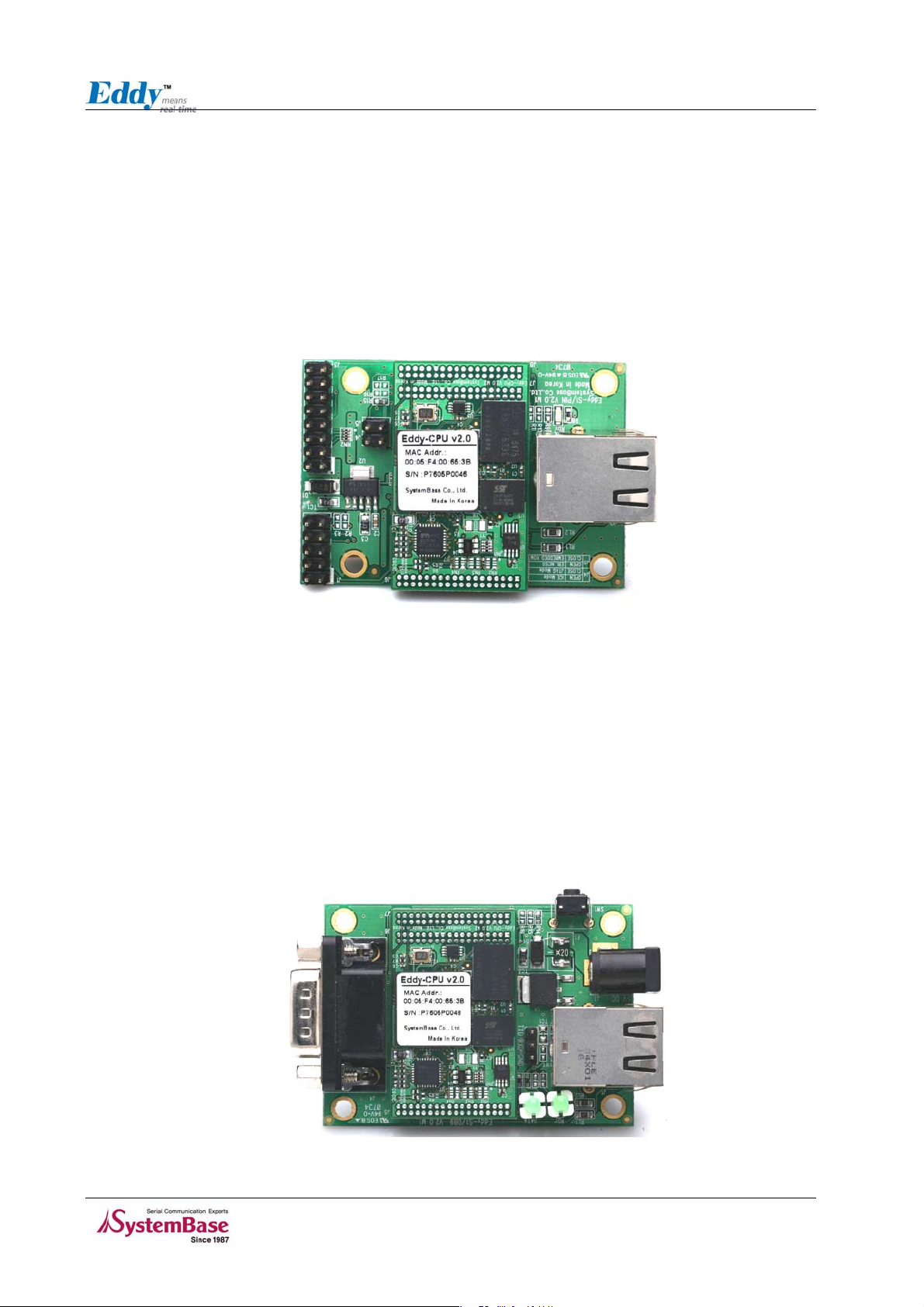
◆ Eddy-CPU
Eddy-CPU is an embedded module based on ATMEL AT91SAM9260-CJ processor with 32MB SDRAM, 4MB
Flash Memory, 1 Ethernet port with 10/100Mbps, 16 bit address / 8 bit data bus interface supporting
external device connection, and maximum 17 programmable IO pins. Programmers can easily
implement RS232/422/485 serial driver or I2C interface with library type example codes and
evaluation kit circuit diagrams.
Eddy-CPU is implemented on a small form factor (42 * 25mm) with on-board memory and integrated
10/100Mbps network interface. Developers can minimize time and cost spent on developing
application products.
Figure 2-1 Eddy-CPU
2-1
Page 10
Chapter 2. Getting Started
◆ Eddy-S1/Pin
RJ-45 Ethernet port is included to provide direct connection to network.
For serial communication, RS232 only or RS422/485 combo interface is available. In the combo
module, RS422/485 setting can be adjusted with software, using web interface.
Acceptable external power input ranges from 3.0 to 5.5V through pin headers.
Please check labeled input voltage on top of the module before supplying power. Improper voltage
feed may damage the module.
Figure 2-2 Eddy-S1/Pin
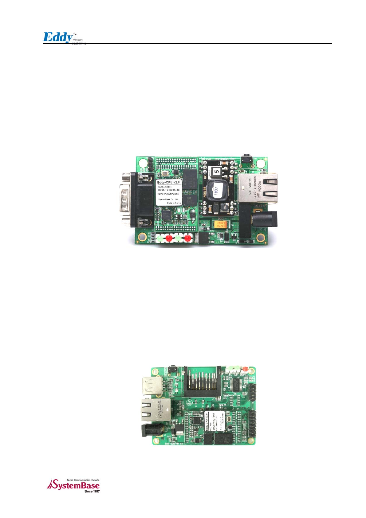
◆
Eddy-S1/DB9
RJ-45 Ethernet port is included to provide direct connection to network.
For serial communication, RS232 only or RS422/485 combo interface is available through DB9 male
connector. In the combo module, RS422/485 setting can be adjusted with software, using web
interface.
External power input is provided as 5V DC Jack.
Please check labeled input voltage on top of the module before supplying power. Improper voltage
feed may damage the module.
Figure 2-3 Eddy-S1/DB9
2-2
Page 11
Chapter 2. Getting Started
◆ Eddy-S1/DB9-PoE
This module can operate as a powered device (PD), which accepts power input from the twisted pair
Category 5 Ethernet cable as specified in IEEE 802.3af Power-over-Ethernet (PoE) standard.
With an auxiliary 5V DC power jack, power supply can be automatically channeled to 5V adaptor when
PSE (Power Sourcing Equipment) is out of order. Seamless power supply is guaranteed. PSE power can
be used again when the PSE resumes to normal operation.
For serial communication, RS232 only or RS422/485 combo interface is available through DB9 male
connector. In the combo module, RS422/485 setting can be adjusted with software, using web
interface.
Figure 2-4 Eddy-S1/DB9-PoE
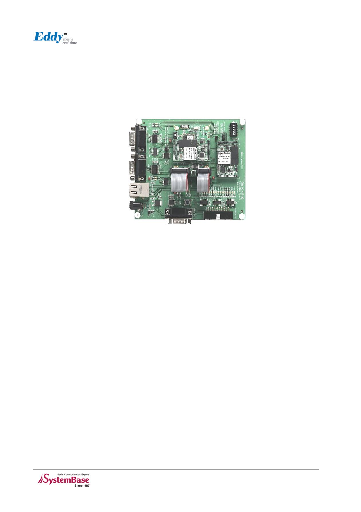
◆ Eddy-S2M/Pin
The model supports MCI ( MultiMedia Card Interface) and USB host port.
The MultiMedia Card Interface (MCI) supports the MultiMedia Card (MMC) Specification V3.11, the SD
Memory Card Specification V1.0.
The USB Host Port integrates a root hub and transceivers on downstream ports. It provides sev-eral
high-speed half-duplex serial communication ports at a baud rate of 12 Mbit/s. Up to 127 USB devices
For two serial communication, RS232 only or RS422/485 combo interface is available through PIN
type connector. In the combo module, RS422/485 setting can be adjusted with software, using web
interface.
Figure 2-5 Eddy-S2M/Pin
2-3
Page 12
Chapter 2. Getting Started
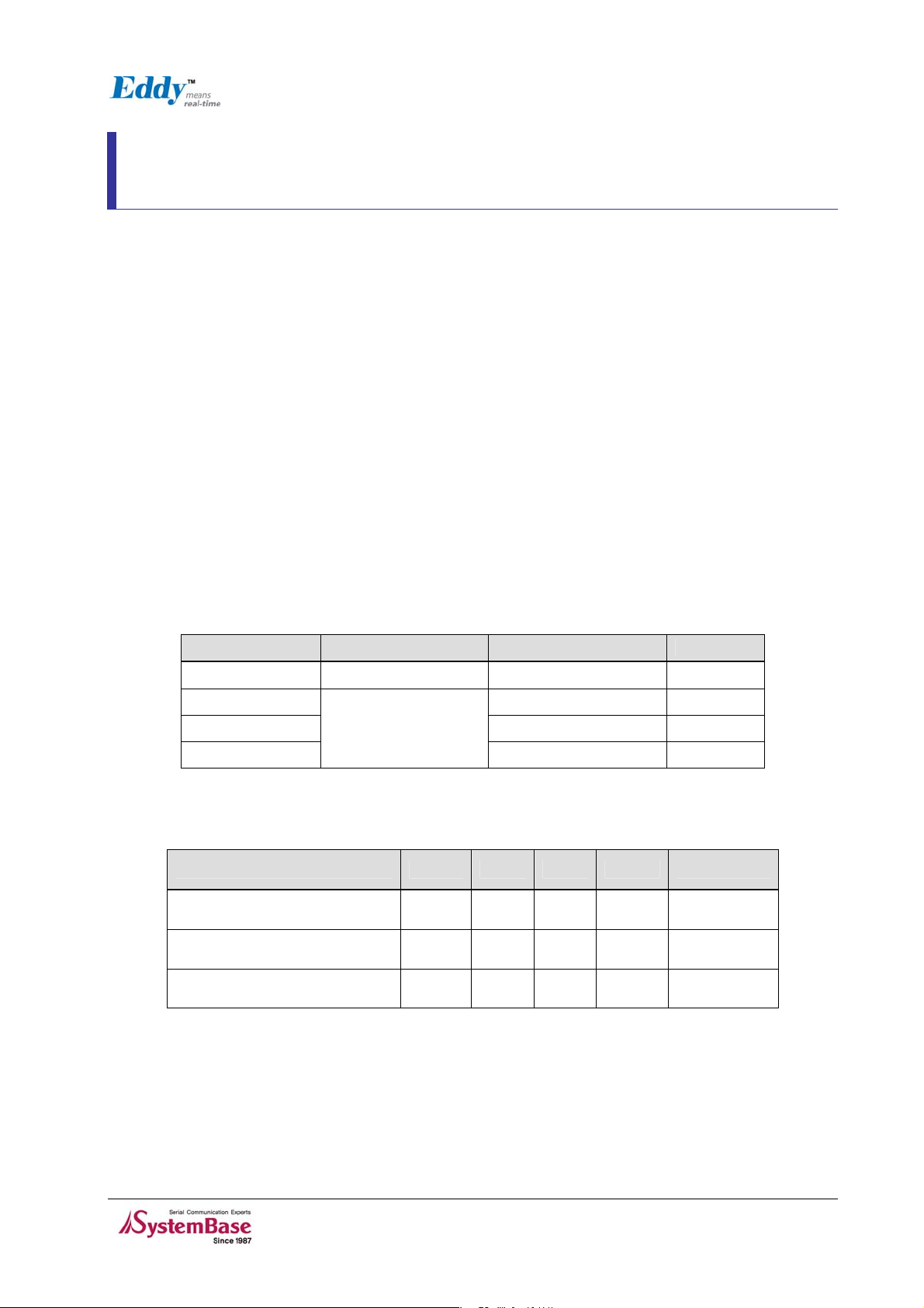
◆
Eddy Development Kit (Eddy DK)
Eddy Development Kit (Eddy DK) helps programmers to test and customize their own Eddy applications
easily, with 1 piece of Eddy-S1/Pin module included in the package. The kit includes evaluation board,
all necessary connectors, and programming environment with documentations and guidelines. Please
refer to Programming Guide included in the Development Kit for detailed information on the DK.
Figure 2-6 Eddy-DK
2-4
Page 13

Chapter 2. Getting Started
◆ Eddy Software Architecture
Figure 2-7 Eddy Software Architecture
2.2 Features
Various features of Eddy make it a universal yet distinctive embedded solution.
Below lists main features of Eddy Serial Series. Others will explicitly appear throughout this guide.
z Premium-level hardware with ARM9 180MHz CPU, 4MB Flash, and 32MB SDRAM
z Selectable RS232 only or RS422/485 combo interfaces
z MMC and SDcard interface
z USB host port
z Max 921.6Kbps serial speed
z Max 8Mbps MCI speed
z Max 8Mbps USB Full speed
z Program and run your own application
z SystemBase SDK and API support for application programming (included in Development Kit)
z Small size to fit in to any hardware
2-5
Page 14

Chapter 2. Getting Started
z 10/100Mbps Ethernet port (auto MDIX)
z SystemBase COM Port Redirector for better adaptability
z Extensive configuration and monitoring with Portview
z Firmware upload with Web, FTP, and TFTP
z Configuration with Web, Telnet, SNMP, and Portview
z Various customizing options
z Standard Linux environment for openness in executable applications
z Multiple Programmable IO pins for customized applications
2-6
Page 15

Chapter 2. Getting Started
2.3 Package Checklist
Eddy package is composed of following components. Make sure every component is included with your
package.
◆ Eddy Package Contents
All module packages include a module and a CD with utilities and documents.
Module 1pc (Eddy-S1/Pin, Eddy-S1/DB9, Eddy-S1/DB9-PoE, Eddy-S2M/Pin)
CD-ROM (Utilities and documents)
2.4 Applications
Eddy can be applied to many practical applications in various fields. Some are presented below.
◆ Factory / Industrial Automation
PLC, Robot arms, Human-Machine Interface, Warehouse rails
Medical instruments, Inspection equipment controllers
Alarming units
◆ Home Appliances / Electronic Devices
Power controller, Gaming machines
Scales, Gas detection units, Water & pollution metering devices
Data collection and distribution units
◆ Financial / Building Automation
Card readers, Barcode scanners, Kiosks, Point-Of-Sale related devices
Serial printers, Cash registers, Credit card authorization terminals
Biometric detection units, Security devices
◆ OEM Device Server Distributors
OEM device server with distributor’s own case & brand
Ready-to-go device or customized application / setup mode can be inserted
2-7
Page 16
Chapter 3. Hardware Description
Chapter 3. Hardware Description
This chapter provides Eddy’s hardware information, including block diagram, layout, pin specifications,
dimensions and other hardware-related issues.
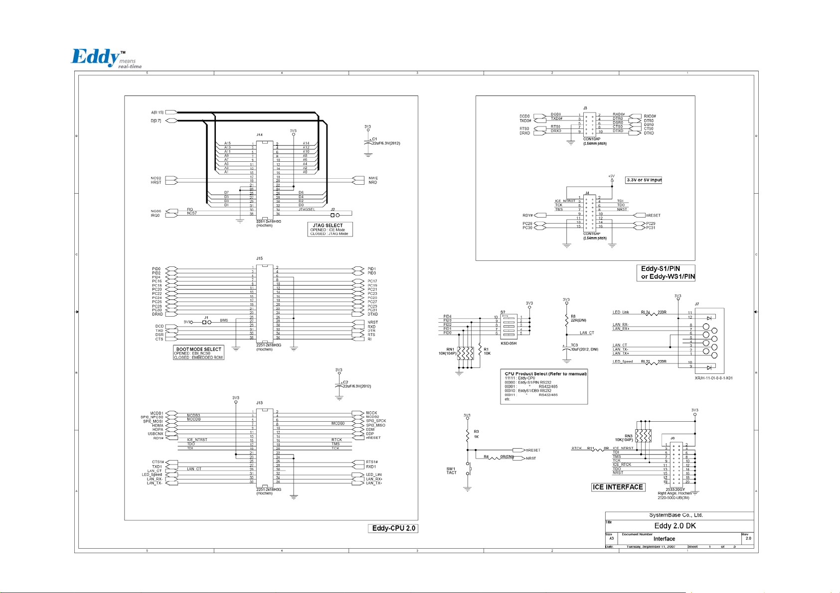
3.1 Eddy-CPU
Ethernet port is provided as pin headers, and the transformer and RJ-45 connector should be manually
implemented by users. (RJ-45 connector with embedded transformer, normally called LAN-Mate or
MAC Jack, can be used as a simpler approach.
16 bit address / 8 bit data bus provides flexibility in external peripheral connectivity and up to 16
programmable IO can be used on user’s side.
Chip Selects
Chip select signal Typical Slave Device Address Range Size
NCS0 Flash ROM 0x10000000~x107FFFFF 4MB
NCS2 0x30000000~
NCS6 0x60000000~
NCS7
Eddy-CPU Operating Conditions
Parameter Symbol Min Typ Max Units
Supply Voltage Vcc 3.0 3.3 3.6 VDC
Supply Current Icc
Operating ambient
temperature
Application
dependent
0x70000000~
-40
T
A
300
85
mA
℃
3-1
Page 17
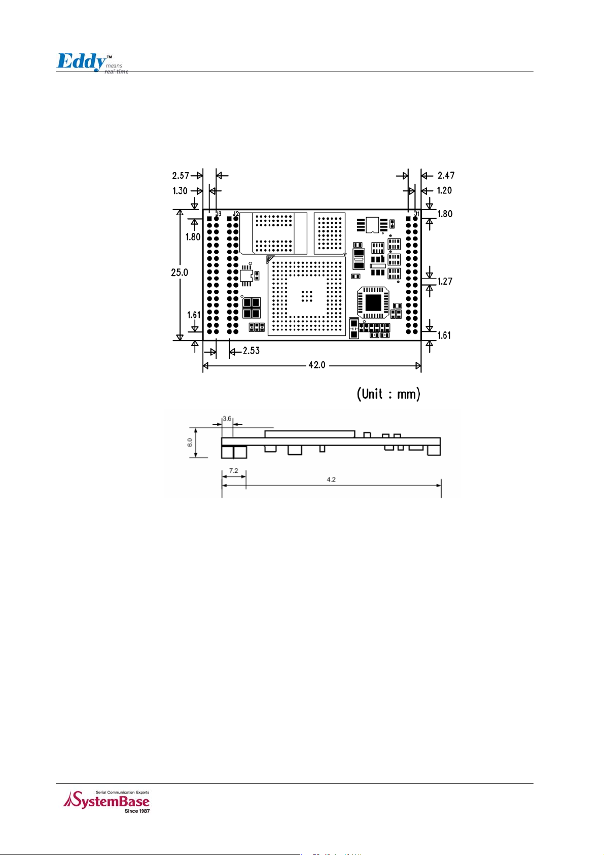
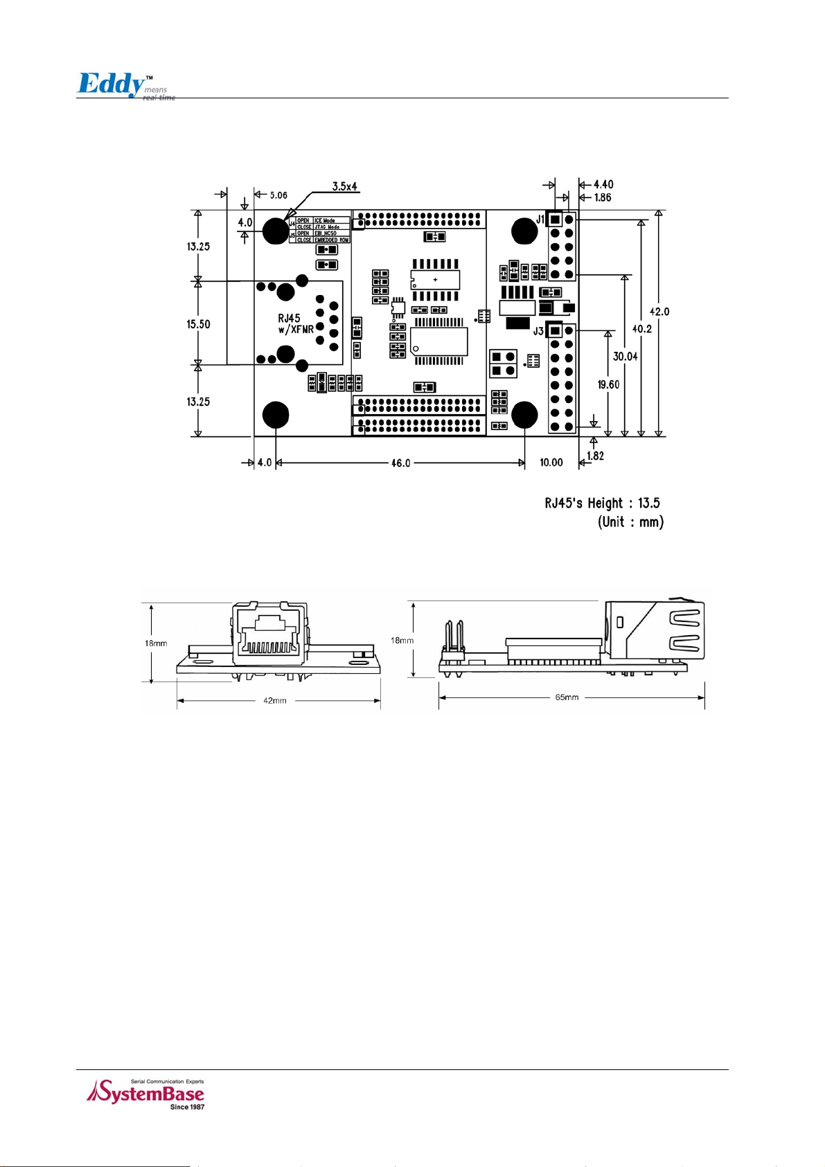
3.1.1 Dimensions
Dimensions of Eddy-CPU are shown below.
Chapter 3. Hardware Description
Figure 3-1 Eddy-CPU front and side view
3-2
Page 18
Chapter 3. Hardware
Description
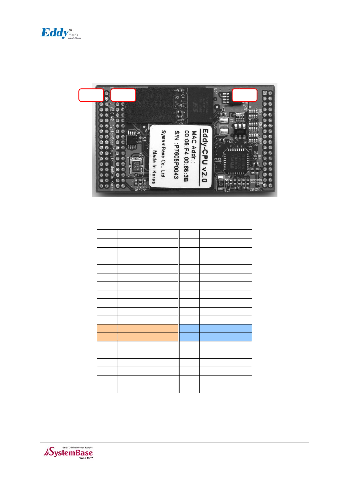
3.1.2 Pin Specifications
Pin specifications are presented below.
J1 Pin J3 Pin J2 Pin
Figure 3-2 Pin Spec
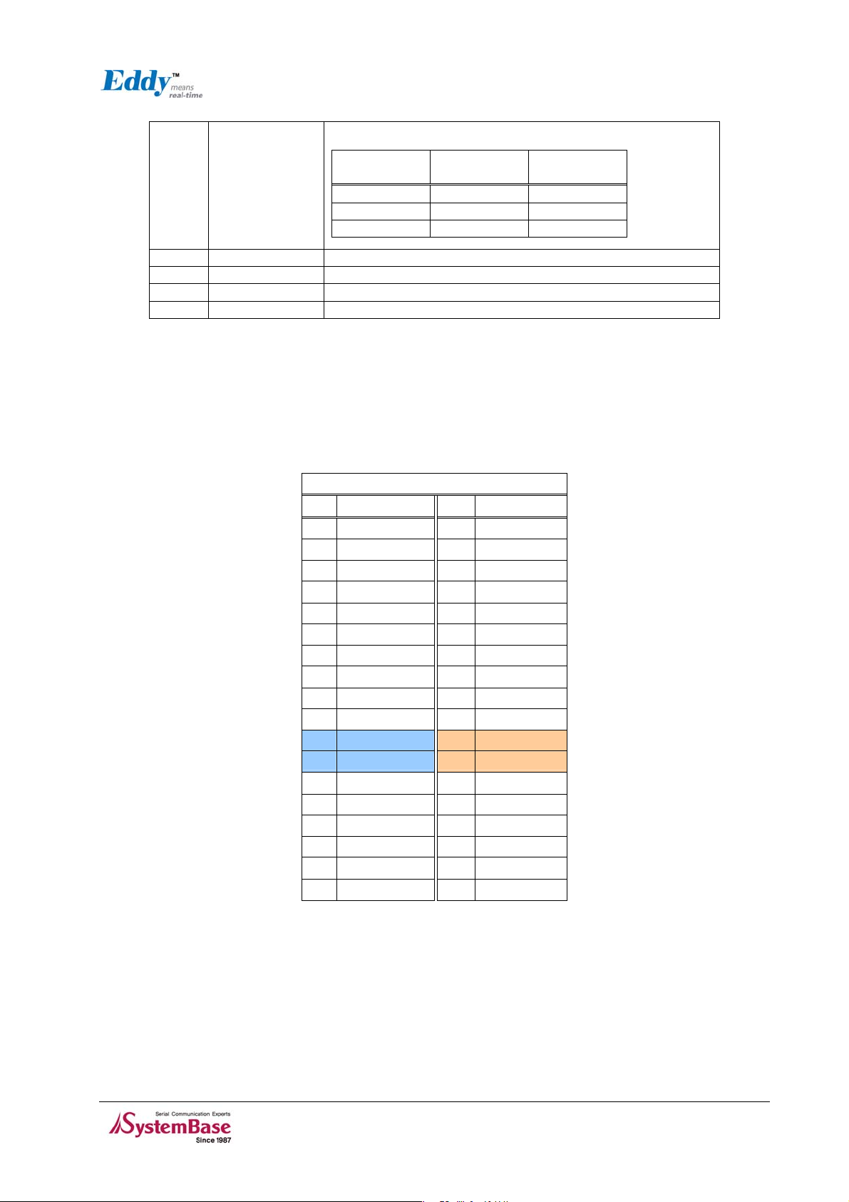
J1 Specifications
Pin Desc. Pin Desc.
1 MCDB1 2 MCCK
3 MCDB3(SPI0_NPCS0)
5 MCCDB(SPI0_MIOSI) 5 SPI0_SPCK
7 HDMA 8 SPI0_MISO
9 HDPA 10 DDM
11 USBCNX 12 DDP
13 RDY# 14 nRESET
15 NTRST 16 RTCK
17 TDO 18 TMS
19 TDI 20 TCK
21 3.3V
23 3.3V
25 CTS1 26 RTS1
27 TXD1 28 RXD1
29 NC 30 NC
31 LED_Speed 32 LED_link
33 LAN_RX- 34 LAN_RX+
35 LAN_TX- 36 LAN_TX+
J1
4 MCDB2
22 GND
24 GND
3-3
Page 19

Chapter 3. Hardware Description
J1 Pin Description
Pin No Name Description
1 MCDB1 Multimedia Card Slot B Data
2 MCCK Multimedia Card Clock
MCDB3
3
(SPI0_NPCS0)
4 MCDB2 Multimedia Card Slot B Data
MCCDB
5
(SPI0_MOSI)
6 SPI0_SPCK SPI Serial Clock
7 HDMA USB Host Port A Data 8 SPI0_MISO SPI Master In Slave Out
9 HDPA USB Host Port A Data +
10 DDM USB Device Port Data 11 USBCNX Used when implementing USB Device Port
12 DDP USB Device Port Data +
13 RDY# Output signal for CPU operation status
14 nRESET Microcontroller Reset input
15 NTRST Test Reset Signal
16 RTCK Return Test Clock
17 TDO Test Data Out
18 TMS Test Mode Select
19 TDI Test Data In
20 TCK Test Clock
21 3.3V 3.0V to 3.6V power input
22 GND Ground
23 3.3V 3.0V to 3.6V power input
24 GND Ground
SPI Master Out Slave In
Power Supplies
Multimedia Card Slot B Data
SPI Peripheral Chip Select 0
Multimedia Card Slot B Command
ICE and JTAG
Universal Synchronous Asynchronous Receiver Transmitter USART1
25 CTS1 USART1 Clear To Send
26 RTS1 USART1 Request To Send
27 TXD1 USART1 Transmit Data
28 RXD1 USART1 Receive Data
29 NC No Connection
30 NC No Connection
Ethernet 10/100
LAN connection speed
31 LED_Speed
Speed Pin State LED
Definition
10Base-T H OFF
100Base-TX
L ON
3-4
Page 20
Chapter 3. Hardware
22
24
36
Description
LAN connection status
Link/Activity
32 LED_link
33 LAN_RX- Physical receive or transmit signal (- differential)
34 LAN_RX+ Physical receive or transmit signal (+ differential)
35 LAN_TX- Physical transmit or receive signal (- differential)
36 LAN_TX+ Physical transmit or receive signal (+ differential)
No Link H OFF
Link L ON
Activity Toggle Blinking
Pin State LED
Definition
J2 Specifications
Connect USB cable to J1 while the jumper is connected to J2, so that applications can be compiled,
linked, created, and uploaded to the Eddy-CPU module. (Please refer to Programmer Guide for more
information.)
J2
Pin Desc. Pin
1 A15 2 A14
3 A13 4 A12
5 A11 5 A10
7 A9 8 A8
9 A7 10
11 A5 12
13 A3 14
15 A1 16
17 NCS2 18
19 HRST 20
21 GND
23 GND
25 D7 26
27 D5 28
29 D3 30
31 D1 32
33 NCS6(FIQ) 34
35 IRQ0(NCS7)
Desc.
A6
A4
A2
A0
NWE
NRD
3.3V
3.3V
D6
D4
D2
D0
JTAGSEL
VDDBU
3-5
Page 21

Chapter 3. Hardware Description
26
J2 Pin Description
Pin No Name Description
1~16 A[15:0] Address Bus 0~15
17 NCS2
18 NWE External device Write Enable signal, active low
19 HRST External device Reset signal, active high
20 NRD External device Read signal
21, 23 GND Ground
22, 24 3.3V 3.0V to 3.6V power input
25~32 D[7:0] Data Bus
33 NCS6/FIQ
34 JTAGSEL
35 NCS7/IRQ0
36 VDDBU
External device Chip Select signal, 256MB memory area
addressable, active low
- External device Chip Select signal, 256MB memory area
addressable, active low
- Fast Interrupt Input
JTAG boundary scan can be used by connecting pin34 and 36.
This pin should not be connected when using ICE(In-Circuit
Emulator) or in normal operation status.
- External device Chip Select signal, 256MB memory
addressable, active low
- External Interrupt Input
JTAG boundary scan can be used by connecting pin34 and 36.
This pin should not be connected when using ICE(In-Circuit
Emulator) or in normal operation status.
J3 Specifications
J3
Pin Desc. Pin
1 PID0 2 PID1
3 PID2 4 PID3
5 PID4 6 GND
7 GPIO1 8 GPIO2
9 GPIO3 10
11 GPIO5 12
13 GPIO7 14
15 GPIO9 16
17 GPIO11 18
19 GPIO13 20
21 GPIO15 22
23 DRXD 24
25 GND
27 BMS 28
29 DCD 30
31 TXD 32
33 DSR 34
35 CTS 36
Desc.
GPIO4
GPIO6
GPIO8
GPIO10
GPIO12
GPIO14
GPIO16
DTXD
GND
NRST
RXD
DTR
RTS
RI
3-6
Page 22

Chapter 3. Hardware
Description
J3 Pin Description
Pin No Name Description
1-5 PID[4:0]
6, 25,
26
7~22 GPIO[1:16]
23 DRXD Debug Receive Data
24 DTXD Debug Transmit Data
27 BMS
28 NRST External device Reset signal, active low signal
29 DCD USART0 Data Carrier Detection
30 RXD USART0 Receive Data
31 TXD USART0 Transmit Data
32 DTR USART0 Data Terminal Ready
33 DSR USART0 Data Set Ready
34 RTS USART0 Request To Send
35 CTS USART0 Carrier To Send
36 RI USART0 Ring Indicator
GND Ground
Universal Synchronous Asynchronous Receiver Transmitter USART0
Product ID only used by the manufacturer.
Please do not work on these pins.
General Purpose In/Out signal
Development Kit’s LED adjustable
Pin State LED
Definition
H ON
Boot Mode Select signal
BMS = 1, Boot on Embedded ROM
BMS = 0, Boot on External Memory
L OFF
Debug Unit - DBGU
Reset/Test
3-7
Page 23
Chapter 3. Hardware Description
3-1
Page 24
Chapter 3. Hardware Description
3-2
Page 25

Chapter 3. Hardware Description
\
3-3
Page 26

Chapter 3. Hardware Description
3.2 Eddy-S1/Pin
Ethernet LAN port is in RJ-45 form factor to provide direct network connection. One serial port is
provided in pin header interface, supporting either RS232 only or RS422/485 combo. Pins can be
connected to any kind of external serial interface of user’s preference.
Figure 3-3 Eddy-S1/Pin – Product and block diagram
3-1
Page 27
3.2.1 Dimensions
Chapter 3. Hardware Description
Figure 3-4 Eddy-S1/Pin Front View
Figure 3-5 Eddy-S1/Pin Side View
3-2
Page 28

Chapter 3. Hardware Description
3.2.2 Pin Specifications
Pin Specification and its usages are as follows.
J3
RJ-45
J1
◆ J1
Serial 10-pin header connector
◇ J1 : RS232
Pin Signal Description
1 DCD Data Carrier Detection (Input)
TXD
GND
RTS
NC
10
RXDDCD
2
DTR
DSR
6
CTS
8
NC
1
34
5
7
9
2 RXD Receive Data (Input)
3 TXD Transmit Data (Output)
4 DTR Data Terminal Ready (Output)
3-3
Page 29

Pin Signal Description
5 GND Ground
6 DSR Data Set Ready (input)
7 RTS Request to Send (Output)
8 CTS Clear to Send (Input)
9, 10 NC No Connection
◇ J1 : RS422 Full Duplex
Pin Signal Description
2 RXD+ Receive differential data positive (Input)
3 TXD+ Transmit differential data positive (Output)
6 RXD- Receive differential data negative (input)
Chapter 3. Hardware Description
7 TXD- Transmit differential data negative (Output)
◇ J1 85 Half : RS4 Duplex
Pin Signal Description
3 TRX+ Transmit/Receive differential data positive
7 TRX- Transmit/Receive differential data negative
◆
J3
6-pin header connector
1
VCC
NTRST
TCK TDO
TMS NRST
RDY# nRESET10
GND GND12
GPIO0
GPIO2
1
5
7
9
11
13
15 16 GPIO3
2
43
6
8
VCC
TDI
GPIO114
3-4
Page 30

Chapter 3. Hardware Description
Pin Signal Description
1,2 VCC 3.0 ~ 5.5V DC input
3 NTRST Test Reset Signal
4 TDI Test Data In
5 TCK Test Clock
6 TDO Test Data Out
7 TMS Test Mode Select
8 NRST Reset signal for external devices
Ready indicator (Active low output)
Processor status can be indicated, when connected as below.
9 RDY#
Connection to external reset switch (Input)
As reset logic is built-in, this pin can be connected directly to the
10 nRESET
11 GND Ground
switch without any additional circuit. When pressing the switch
for more than 5 seconds (low input), factory default settings are
restored.
12 GND Ground
13 GPIO0 Programmable I/O 0 (user-defined I/O)
14 GPIO1 Programmable I/O 1 (user-defined I/O)
15 GPIO2 Programmable I/O 2 (user-defined I/O)
16 GPIO3 Programmable I/O 3 (user-defined I/O)
3-5
Page 31

◆ RJ-45 Ethernet
Pin Signal Description
1 TXD+ Physical transmit or receive signal (+ differential)
2 TXD- Physical transmit or receive signal (- differential)
Chapter 3. Hardware Description
3 RXD+ Physical receive or transmit signal (+ differential)
6 RXD- Physical receive or transmit signal (- differential)
LED Description
Left Green
(LAN_Speed)
Right Yellow
(LAN_LINK)
Speed Pin State
10Base-T H OFF
100Base-TX L ON
Link/Activity Pin State
No Link H OFF
Link L ON
Activity Toggle Blinking
LAN connection speed
LED Definition
LAN connection status
LED Definition
3.2.3 Serial Interface Setup
Eddy supports RS232 only or RS422/485 combo by hardware. In combo modules, RS422/485 interface
can be configured by software.
3-6
Page 32

Chapter 3. Hardware Description
3.2.4 Terminal Resistors
Terminal Resistors are installed in RS422 or RS485 communication to prevent noise and distortion of
long distance data transfer. They help by matching impedance in communication line, and normally
120 ohm resistors are used. The decision to use terminal resistor lies with the user, and one may
choose to either install or not install terminal resistors in RS422 or RS485 mode. Installation can be
done by connecting RX+ and RX- pin on J1 pin header to the resistor if in RS422 mode, or TRX+ and
TRX- pin in RS485 mode.
3.2.5 Terminal Resistor Installation Guide
◆ RS422
Install terminal resistors at each end (terminal)
RS422 Dev ice A
TXD+
TXD-
RXD+
RXD-
When using RS422 Point to P oint Mode
Terminal REG
120R
120R
Terminal REG
RS422 Dev ice B
RXD+
RXD-
TXD+
TXD-
RS422 Master Device
TXD+
TXD-
RXD+
RXD-
When us ing RS422 Multi-Drop Mode
120R
Terminal REG
RS422 Slave Dev ice A
RXD+
RXD-
TXD+
TXD-
RS422 Slave Dev ice B
RXD+
RXD-
TXD+
TXD-
RS422 Slave Dev ice N
120R
Terminal REG
RXD+
RXD-
TXD+
TXD-
◆ RS485
Install terminal resistors only at each end (not in the middle ones in Multi-Drop structure)
RS485 Device D
TRXD-
TRXD+
TRXD-
TRXD+
RS485 Device G
Terminal REG
TRXD-
TRXD+
120R
RS485 Device N
RS485 Device A
TRXD-
120R
Terminal REG
RS485 Device B
TRXD-
TRXD+
RS485 Device E
RS485 Device C
TRXD-
TRXD+
TRXD-
TRXD+
RS485 Device F
Figure 3-6 RS485 Terminal Registor
TRXD+TRXD+
TRXD-
3-7
Page 33

Chapter 3. Hardware Description
3.3 Eddy-S1/DB9
Ethernet LAN port is in RJ-45 form factor to provide direct network connection. Unlike other modules,
this model can be applied without any connection interface.
For serial communication, RS232 only or RS422/485 combo interface is available through DB9 male
connector. In the combo module, RS422/485 setting can be adjusted with software, using web
interface.
RJ45
w/LED & XFMR
RDY
DATA
32MB
SDRAM
4MB Flash
Eddy-CPU
RESET
5V PWR
Regulator
Ethernet
10/100M
GPIO
16ea
ARM926EJ-S
PoE PD Module
200MIPS
Serial Driver
DB-9M
RS-232 or RS422/485
Figure 3-7 Eddy-S1/DB9 – Product Picture and Block Diagram
3-8
Page 34

Chapter 3. Hardware Description
3.3.1 Dimensions
Figure 3-8 Eddy-S1/DB9 Front View
Figure 3-9 Eddy-S1/DB9 Side View
3-9
Page 35

3.3.2 Pin Specifications
Pin Specification and its usages are as follows
DB9
Chapter 3. Hardware Description
Reset switch
Power Jack
RJ-45
LED
◆ Power JACK
Contact Polarity
Center +5VDC ± 5%(over 400mA )
Outer Ground
3-10
Page 36

Chapter 3. Hardware Description
◆ DB9
Serial Connector
◆ RS232
Pin Signal Description
1 DCD Data Carrier Detection (Input)
2 RXD Receive Data (Input)
3 TXD Transmit Data (Output)
4 DTR Data Terminal Ready (Output)
5 GND Ground
6 DSR Data Set Ready (input)
7 RTS Request to Send (Output)
8 CTS Clear to Send (Input)
9 RI Ring Indicator (Input)
◆ RS485 Half Duplex
Pin Signal Description
3 TRX+ Transmit/Receive differential data positive
7 TRX- Transmit/Receive differential data negative
3-11
Page 37

◆ RS422 Full Duplex
Pin Signal Description
2 RXD+ Receive differential data positive (Input)
3 TXD+ Transmit differential data positive (Output)
6 RXD- Receive differential data negative (input)
7 TXD- Transmit differential data negative (Output)
◆ LED
Pin Signal Description
1 READY Indicates the processor status
2 DATA LED ON when serial data is transmitted
◆ RJ-45 Port
Chapter 3. Hardware Description
Pin Signal Description
1 TXD+ Physical transmit or receive signal (+ differential)
2 TXD- Physical transmit or receive signal (- differential)
3 RXD+ Physical receive or transmit signal (+ differential)
6 RXD- Physical receive or transmit signal (- differential)
LED Description
Left Green
(LAN_Speed)
Speed Pin State
10Base-T H OFF
100Base-TX L ON
LAN connection speed
LED Definition
3-12
Page 38

Chapter 3. Hardware Description
Pin Signal Description
LAN connection status
Right Yellow
(LAN_LINK)
Link/Activity Pin State
No Link H OFF
Link L ON
Activity Toggle Blinking
LED Definition
3-13
Page 39

Chapter 3. Hardware Description
3.4 Eddy-S1/DB9-PoE
This module can operate as a powered device (PD), which accepts power input from the twisted pair
Category 5 Ethernet cable as specified in IEEE 802.3af Power-over-Ethernet (PoE) standard.
With a backup 5V DC power jack, power supply can be automatically channeled to 5V adaptor when
PSE (Power Sourcing Equipment) is out of order. Seamless power supply is guaranteed. PSE power can
be used again when the PSE is in normal operation.
For serial communication, RS232 only or RS422/485 combo interface is available through DB9 male
connector. In the combo module, RS422/485 setting can be adjusted with software, using web
interface.
Figure 3-10 Eddy-S1/DB9-PoE – Product Picture and Block Diagram
3-14
Page 40

Chapter 3. Hardware Description
3.4.1 Dimensions
Figure 3-11 Eddy-S1/DB9-PoE Front View
Figure 3-12 Eddy-S1/DB9-PoE Side View
3-15
Page 41

3.4.2 Pin Specifications
Pin Specification and its usages are as follows.
Chapter 3. Hardware Description
LED
Power Jack
RJ-45
Reset Switch
◆ Power JACK
DB9
Contact Polarity
Center +5VDC ± 5%(400mA or above)
Outer Ground
3-16
Page 42

Chapter 3. Hardware Description
◆ DB9
Serial Connector
◆ RS232
Pin Signal Description
1 DCD Data Carrier Detection (Input)
2 RXD Receive Data (Input)
3 TXD Transmit Data (Output)
4 DTR Data Terminal Ready (Output)
5 GND Ground
6 DSR Data Set Ready (input)
7 RTS Request to Send (Output)
8 CTS Clear to Send (Input)
9 RI Ring Indicator (Input)
◆ RS485 Half Duplex
Pin Signal Description
3 TRX+ Transmit/Receive differential data positive
7 TRX- Transmit/Receive differential data negative
3-17
Page 43

◆ RS422 Full Duplex
Pin Signal Description
2 RXD+ Receive differential data positive (Input)
3 TXD+ Transmit differential data positive (Output)
6 RXD- Receive differential data negative (input)
7 TXD- Transmit differential data negative (Output)
◆ LED
Pin Signal Description
1 POWER LED ON when power is on
2 TXD LED ON when serial data is transmitted
Chapter 3. Hardware Description
3 RXD LED ON when serial data is received.
4 READY
Indicates the processor status
3-18
Page 44

Chapter 3. Hardware Description
◆ RJ-45 Port(w/PoE PD Functionality)
Pin Signal Description
1 TXD+ Physical transmit or receive signal (+ differential)
2 TXD- Physical transmit or receive signal (- differential)
3 RXD+ Physical receive or transmit signal (+ differential)
4 Vin+ PSE positive connection
5 Vin+ PSE positive connection
6 RXD- Physical receive or transmit signal (- differential)
7 Vin- PSE negative connection
8 Vin- PSE negative connection
LED Description
Left Green
(LAN_Speed)
Right Yellow
(LAN_LINK)
Speed Pin State
10Base-T H OFF
100Base-TX L ON
Link/Activity Pin State
No Link H OFF
Link L ON
Activity Toggle Blinking
LAN connection speed
LED Definition
LAN connection status
LED Definition
3-19
Page 45

Chapter 3. Hardware Description
3.5 Eddy-S2M/Pin
This model supports MCI ( MultiMedia Card Interface) and USB host port.
The MultiMedia Card Interface (MCI) supports the MultiMedia Card (MMC) Specification V3.11 and the
SD Memory Card Specification V1.0.
The USB Host Port integrates a root hub and transceivers on downstream ports. It provides several
high-speed half-duplex serial communication ports at a baud rate of 12 Mbit/s, up to 127 USB devices.
Two serial ports are provided in PIN connector form. Two types of model are available where the
standard models supports RS232 and combo models supports RS422/RS485. RS422 and RS485 is
software selectable, and can be adjusted through web browser interface.
Figure 3-13 Eddy-S2M/Pin – Product Picture and Block Diagram
3-20
Page 46

Chapter 3. Hardware Description
3.5.1 Dimensions
Figure 3-14 Eddy-S1/DB9-PoE Front View
Figure 3-15 Eddy-S1/DB9-PoE Side View
3-21
Page 47

3.5.2 Pin Specifications
Pin Specification and its usages are as follows.
Reset Switch
Chapter 3. Hardware Description
MCI slot
LED
USB Host
RJ-45
Power Jack
◆ Power JACK
J9 PIN
J8 PIN
figure 3-16 Eddy-S2M/Pin Pin Spec
Contact Polarity
Center +5VDC ± 5%(400mA or above)
Outer Ground
3-22
Page 48

Chapter 3. Hardware Description
figure 3-17 J8 PIN header
◇ J8 : RS232
Pin Signal Description
1 DCD Data Carrier Detection (Input)
2 RXD Receive Data (Input)
3 TXD Transmit Data (Output)
4 DTR Data Terminal Ready (Output)
5 GND Ground
6 DSR Data Set Ready (input)
7 RTS Request to Send (Output)
8 CTS Clear to Send (Input)
9,10 NC No Connection
◇ J8 : RS422 Full Duplex
Pin Signal Description
2 RXD+ Receive differential data positive (Input)
3 TXD+ Transmit differential data positive (Output)
6 RXD- Receive differential data negative (input)
7 TXD- Transmit differential data negative (Output)
◇ J8 : RS485 Half Duplex
Pin Signal Description
3 TRX+ Transmit/Receive differential data positive
7 TRX- Transmit/Receive differential data negative
3-23
Page 49

◆ J9
16-pin header connector
figure 3-18 J9 PIN header
Pin Signal Description
1, 2 VCC 3.0~5.5V DC input
Chapter 3. Hardware Description
3 RXD Receive Data (Input)
4 TXD Transmit Data (Output)
5 RTS Request to Send (Output)
6 CTS Clear to Send (Input)
7,8 NC No Connection
Ready indicator (Active low output)
Processor status can be indicated, when connected as below.
9 RDY#
Connection to external reset switch (Input)
As reset logic is built-in, this pin can be connected directly to the
10 nRESET
11 GND Ground
12 GND Ground
switch without any additional circuit. When pressing the switch
for more than 5 seconds (low input), factory default settings are
restored.
13 GPIO0 Programmable I/O 0 (user-defined I/O)
14 GPIO1 Programmable I/O 1 (user-defined I/O)
15 GPIO2 Programmable I/O 2 (user-defined I/O)
16 GPIO3 Programmable I/O 3 (user-defined I/O)
3-24
Page 50

Chapter 3. Hardware Description
◇ J9 : RS422 Full Duplex
Pin Signal Description
3 RXD+ Receive differential data positive (Input)
4 TXD+ Transmit differential data positive (Output)
5 RXD- Receive differential data negative (input)
6 TXD- Transmit differential data negative (Output)
◇ J9 : RS485 Half Duplex
Pin Signal Description
4 TRX+ Transmit/Receive differential data positive
5 TRX- Transmit/Receive differential data negative
◆ RJ-45 포트
Pin Signal Description
1 TXD+ Physical transmit or receive signal (+ differential)
2 TXD- Physical transmit or receive signal (- differential)
3 RXD+ Physical receive or transmit signal (+ differential)
6 RXD- Physical receive or transmit signal (- differential)
LED Description
Left Green
(LAN_Speed)
Speed Pin State
10Base-T H OFF
100Base-TX L ON
LAN connection speed
LED Definition
3-25
Page 51

Pin Signal Description
LAN connection status
Right Yellow
(LAN_LINK)
Link/Activity Pin State
No Link H OFF
Link L ON
Activity Toggle Blinking
3.5.3 Eddy-S2M/Pin JIG (Pin-to-DB9 gender)
Eddy-S2M/Pin JIG is provided as a Pin-to-DB9 gender for Eddy-S2M/Pin module. Eddy-S2M/Pin JIG is
used for connections to DB9 interfaces. It can also be used as Eddy-S2M/Pin module’s GPIO status
checker through its LEDs.
Eddy-S2M/Pin JIG is included in Eddy-S2M/Pin package and is not sold separately.
◆ Eddy-S2M/Pin JIG (DB9 to PIN connector)
Chapter 3. Hardware Description
LED Definition
figure 3-19 Eddy-S2M/Pin JIG
Serial Connector
3-26
Page 52

Chapter 3. Hardware Description
◆ RS232
Pin Signal Description
1 DCD Data Carrier Detection (Input)
2 RXD Receive Data (Input)
3 TXD Transmit Data (Output)
4 DTR Data Terminal Ready (Output)
5 GND Ground
6 DSR Data Set Ready (input)
7 RTS Request to Send (Output)
8 CTS Clear to Send (Input)
9 RI Ring Indicator (Input)
◆ RS485 Half Duplex
Pin Signal Description
3 TRX+ Transmit/Receive differential data positive
7 TRX- Transmit/Receive differential data negative
◆ RS422 Full Duplex
Pin Signal Description
2 RXD+ Receive differential data positive (Input)
3 TXD+ Transmit differential data positive (Output)
6 RXD- Receive differential data negative (input)
7 TXD- Transmit differential data negative (Output)
◆ LED
LED Signal Description
1 GPIO0 Programmable I/O 1 (user-defined I/O)
2 GPIO1 Programmable I/O 2 (user-defined I/O)
3-27
Page 53

Chapter 3. Hardware Description
LED Signal Description
3 GPIO2 Programmable I/O 3 (user-defined I/O)
4 GPIO3 Programmable I/O 4 (user-defined I/O)
Processor status can be indicated, when connected as
5 READY
below.
3-28
Page 54

Chapter 4. Integration
Chapter 4. Integration
This chapter explains how you can make Eddy to communicate. It deals with LAN and pin header
connection guides for Eddy to operate together with the target serial device.
Follow these steps to connect Eddy to the device and network.
4.1 Connection Guide
1) LAN
In order to connect Eddy to network, you need to use RJ45 Ethernet port. It supports both 10Mbps and
100Mbps Ethernet connection (auto-sensing). Since Eddy’s LAN port supports MDIX function, you can
either connect cross LAN cable or direct LAN cable. Plug one end of a LAN cable to Eddy and the other
end to a hub, switch, or any other network device that can provide you with network access.
2) Pin Header
For those models with pin header interface, it is important that you clearly understand which pins you
are to connect and how you connect them. For pin specifications, please refer to Chapter 3. Hardware
Description. Please note that not all pins must be used. You can selectively connect only those pins
relevant to your application.
3) DB9
For Eddy-S1/DB9, you can simply connect Eddy to the destination serial device with a DB9 cable. For
pin specifications, please refer to Chapter 3.
4-1
Page 55

Chapter 4. Integration
4.2 First-time Bootup
First of all, please make sure the power input you supply to the module is corresponding with the
Eddy model that you have. If an appropriate power input has been successfully supplied, Eddy will
power on and start booting. For those models that require power input through pins (this will leave
out DB9 models), you can notice that there are two Power In pins per serial port. It is a good practice
to connect both power pins to the power supply for more stability in operation.
Although there is no power LED to check the status, you can check by LEDs on the RJ45 Ethernet port.
LED status operation is described in Chapter 3. Hardware Description
simply use a 5V DC power adaptor. In models with Pin Header, issue 3.3 ~ 5V power input.
An IP address is required to access Eddy’s web interface or telnet command-line configuration tool. By
factory default, Eddy is assigned a static IP address. After the initial connection, you can either
manually assign a different IP address or set Eddy to automatically get an IP address from a DHCP
server. While this depends on your network environment and policy, it is strongly recommended that
you assign Eddy with a unique static IP.
. In models with DB9, you can
4-2
Page 56

Chapter 4. Integration
4.3 Connecting to Eddy with IP address
In order to view current Eddy’s settings or modify them, you need to make a Web or Telnet connection
to Eddy. IP address is required information to make a connection.
There are two ways you can know the current IP address of Eddy.
First is to use a built-in, alias IP address of “10.10.1.1”.
Second is to use “Detector” application provided in the Utility & Documents CD. This application
allows searching for Eddy modules on the network.
◆
The factory default IP address: 192.168.0.223
Eddy’s default IP address is set to 192.168.0.223. In order to connect with this address, you need to
change network configurations so that your PC can connect to the IP 192.168.0.223. Please refer to an
example below, and note that values don’t necessarily have to be identical to the example below.
Figure 4-1 Connecting to the default IP address
4-3
Page 57

Chapter 4. Integration
◆
Factory default alias IP address: 10.10.1.1
In case you configure Eddy to use DHCP to obtain an IP address automatically, you might find it hard to
know the IP address to connect to. To provide users with an easier way to know the current IP address,
Eddy has a fixed alias IP that is always accessible. Use the address below whenever you cannot find
out Eddy’s IP address.
In order to connect with this address, you need to change network configurations so that your PC can
connect to the IP 10.10.1.1. Please refer to an example below, and note that values do not necessarily
have to be identical to the example below.
Figure 4-2. Connecting to alias IP address
◆ Connection via Detector
By running the Detector program in the Utility & Documents CD included in the Eddy package, you can
dynamically search for all Eddy modules on the network and connect to any module. (For more
information on Detector, please refer to the Portview manual in the Utility & Documents CD included
in the Eddy package)
4-4
Page 58

Chapter 4. Integration
After running Detector, click Search button on the top-left to display all Eddy modules on the network.
Select the module that you would make a connection to, and click Telnet or Web to connect to the
module via Telnet or Web, respectively.
Figure 4-3 Detector Layout
If Eddy module is not on the same network as the PC you are working on, use “IP Configure” button to
temporarily assign an IP address that you would like to make a Web or Telnet connection to. If you
assign a temporary IP address to Eddy, you need to to change the IP address and restart in Web or
Telnet.
Figure 4-4 Setting Eddy with temporary IP address
Now you are ready to connect to Eddy! There are three options to configure Eddy.
1) Web
You can easily configure Eddy with web interface, accessible from any web browser. For more
information, please refer to
2) Telnet
You can configure Eddy with commands after accessing Eddy through Telnet. For more information,
Chapter 5. Configuration via Web
.
please refer to Chapter 6. Configuration via Telnet
3) Portview
You can use a Windows-based utility Portview from SystemBase to monitor Eddy. For more information
on using the utility for your administration purpose, please refer to Portview User Guide.
.
4-5
Page 59

4.4 Eddy-S2M/Pin’s MCI & USB Host Port
y
The following contents outline the usage of Eddy-S2M/Pin’s MCI & USB Host Port.
Using MCI slot
MMC and SDCards can be used through MCI slot.
Please note that MCI and SDCard must be inserted before power is induced to Eddy-S2M/Pin module.
MMC or SDCards are automatically recognized as a new disk space in " /tmp/mmc " folder. If memory
card is not inserted to the MCI slot, " /tmp/mmc " folder will not be created.
To check memory card’s current disk space information, type in "du -sk /tmp/mmc" or "df /tmp/mmc"
commands via telnet. Following example displays status of a memory card with 1GB memory storage
capacity.
Chapter 4. Integration
Eddy login: edd
Password:
# pwd
/tmp
# ls
ifstate login.pw thttpd.log wtmp
login.id mmc thttpd.pid
# du -sk /tmp/mmc
16 /tmp/mmc
# df /tmp/mmc
Filesystem Size Used Available Use% Mounted on
/dev/mmcblk0p1 970.1M 1.5M 968.6M 0% /tmp/mmc
#
Using USB host port
An USB memory stick or USB hub can be attached to Eddy-S2M/Pin module’s USB host port. If other
USB devices are to be attached to this port, device drivers for the devices must be first created and
loaded to Eddy-S2M/Pin module using Eddy-DK.
Following example displays procedures for USB memory stick usage.
z Insert the USB memory stick to USB host port and connect telnet.
z Type in "fdisk -l " or "ls -al /dev/sd* " command to check USB memory stick is properly
inserted.
z Create a folder using “mkdir /tmp/usb” command.
z Mount "/tmp/usb" folder using "mount -t vfat /dev/sda1 /tmp/usb" command.
z Always unmount USB memory stick with "umount <mounted folder> " command,
before removing USB memory stick from USB host port.
If more than one USB memory stick is connected using a USB hub, each memory stick would be
4-6
Page 60

Chapter 4. Integration
y
recognized as /dev/sdb1, /dev/sdc1, /dev/sdd1…. Each device must be mounted for proper use.
Following displays an example of two USB memory stick connection with a hub.
Eddy login: edd
Password:
# fdisk -l
Disk /dev/sda: 4068 MB, 4068474880 bytes
51 heads, 50 sectors/track, 3116 cylinders
Units = cylinders of 2550 * 512 = 1305600 bytes
Device Boot Start End Blocks Id System
/dev/sda1 1 3117 3973116 b Win95 FAT32
Disk /dev/sdb: 1020 MB, 1020788736 bytes
32 heads, 63 sectors/track, 988 cylinders
Units = cylinders of 2016 * 512 = 1032192 bytes
Device Boot Start End Blocks Id System
/dev/sdb1 * 1 989 996750+ 6 FAT16
Partition 1 has different physical/logical endings:
phys=(987, 31, 63) logical=(988, 30, 30)
# ls -al /dev/sd*
brw-rw---- 1 root root 8, 0 Jan 1 00:04 /dev/sda
brw-rw---- 1 root root 8, 1 Jan 1 00:04 /dev/sda1
brw-rw---- 1 root root 8, 2 Jan 1 00:04 /dev/sdb
brw-rw---- 1 root root 8, 3 Jan 1 00:04 /dev/sdb1
# ls -al
drwxrwxrwt 3 root root 200 Jan 1 00:00 .
# pwd
/tmp
# mkdir usb1
# mkdir usb2
# mount -t vfat /dev/sda1 usb1
# mount -t vfat /dev/sdb1 usb2
# df /tmp/usb*
Filesystem Size Used Available Use% Mounted on
/dev/sda1 3.8G 3.2G 547.3M 86% /tmp/usb1
/dev/sdb1 973.1M 217.6M 755.5M 22% /tmp/usb2
#
4-7
Page 61

Chapter 5. Configuration via Web
Chapter 5. Configuration via Web
5.1 Connection
Open your favorite web browser and enter the IP address of Eddy to access Eddy’s web manager. Once
you are successfully connected, the following front page will show up. You need to enter appropriate
username and password to login. Please note that this username and password is used as
authentication method for Telnet as well.
◆ Factory default username: eddy
◆ Factory default password: 99999999
TM
Figure 5-1 Eddy Login Page
5-1
Page 62

Chapter 5. Configuration via Web
5.2 Setup Menu
If login process is successful, you will see a web manager’s main page, showing summary of your
device. On the left, you will see a setup menu, and you can navigate through these options.
Figure 5-2 Main Page
Main features of Setup Menu are as follows.
Table 5-1 Main features of Setup Menu
Menu Descriptions
Summary View a summary of Eddy.
Network Settings Configure network connection settings.
Serial Settings
GPIO Settings Configure programmable I/O pins.
Change Password Change ID and password for both Web and Telnet interface.
Update Firmware Update Eddy’s firmware.
Factory Default Restore all the factory default settings.
Save & Reboot Save the configurations and reboot Eddy.
Configure detailed operation environment for serial
communication.
5-2
Page 63

Chapter 5. Configuration via Web
5.3 Network Settings
Configure general network environment and network management. After changing values, you need to
click ‘Submit’ button. Then you will see the same page with modified values. Please note that you
have to ‘Save & Reboot’ in order to see these changes in effect. Changes will be discarded if you do
not save current settings.
Figure 5-3 Network Settings Configuration Page
Main features for General Configuration is as follows.
Table 5-2 Main features of General Configuration
Menu Default Descriptions
Device
Name
Line Type Static IP
IP Address 192.168.0.223
Eddy
Current IP address Eddy is assigned to.
Name of the current device
IP obtaining method for Eddy’s network connection.
(When line type is Static IP, manually enter an
appropriate IP address. When line type is DHCP, current
IP is displayed, but it is not editable.)
5-3
Page 64

Chapter 5. Configuration via Web
Current subnet mask Eddy is assigned to.
(When line type is Static IP, manually enter an
Subnet
Mask
255.255.255.0
appropriate subnet mask.When line type is DHCP,
current subnet mask is displayed, but it is not
editable.)
Current default gateway Eddy is assigned to
(When line type is Static IP, manually enter an
Gateway 192.168.0.254
appropriate default gateway. When line type is DHCP,
current default gateway is displayed, but it is not
editable.)..
DNS 168.126.63.1 DNS (Domain Name Service) IP address
Main features for Network Service Configuration are as follows.
Table 5-3 Main features for Network Service Configuration
Menu Default Descriptions
Set the IP address and the port number of the PC
Portview
IP / Port
0.0.0.0 / 4000
where Portview is installed. For more information on
Portview, please refer to the Portview User Manual.
DDNS
(Username/
203.32.117.1
Password)
SNMP Disable
Telnet Service Enable
FTP Service Enable
Web Service Enable
LemonIDE
Target Agent
Disable
If IP is set to 0.0.0.0, this feature is disabled
Register DDNS server’s IP address for DDNS service.
DDNS service used in Eddy is supported by
http://ddns.nu
default ID is eddy and default password is 99999999
if you want to used this ,you should register your own
in http://ddns.nu
Enable or disable SNMP(Simple Network Management
Protocol) support
▪MIB-II (RFC 1213): System, Interface, IP, ICMP, TCP, UDP
▪MIB-I (RFC 1317): Serial Interface
Enable or disable Telnet service.
If disabled, you cannot connect to Eddy via Telnet.
Enable or disable FTP service.
If disabled, you cannot connect to Eddy via FTP.
Enable or disable Web service.
If disabled, you cannot connect to Eddy via Web.
Enable or disable remote debugging function used by Eddy
development environment, LemonIDE®..
For more information, please refer to LemonIDE user
manual in the SDK CD included in Eddy-DK package.
5-4
Page 65

Chapter 5. Configuration via Web
5.4 Serial Settings
You can set the communication and operation environment for the serial port. After changing values,
you need to click ‘Submit’ button. Then you will see the same page with modified values. Please note
that you have to ‘Save & Reboot’ in order to see these changes in effect. Changes will be discarded if
you do not save current settings.
Figure 5-4 Serial settings page
Serial communication settings for Eddy-S1/Pin, S1/TTL, S2/Pin are as follows.
Table 5-4 Main features for Serial Settings
Menu Default Descriptions
▪Eddy-S1/Pin, S1/DB9, S1/DB9-PoE
Only RS232 interface supported. Fixed. (Default: RS232)
▪Eddy-S1/Pin-C, S1/DB9-C, S1/DB9-PoE-C
Interface
RS232 or
RS422
RS422 or RS485 interface is supported. By software, you can select
one of these interfaces. (Default: RS422)
▪Eddy-CPU
User decides the serial interface, meaning Web or Telnet
configuration is not possible. For more information on interface
5-5
Page 66

Chapter 5. Configuration via Web
Menu Default Descriptions
configuration, please refer to Chapter 3. Hardware Description.
Select the operation protocol, which the serial port would use.
▪Disable
Do not use this port.
▪COM
Use the serial port of Eddy as the COM ports of Windows
2000/XP/2003/Vista operated PC.
▪TCP Server
Eddy works as a socket server, waiting for the client connection on
the network.
Socket number for awaiting connections can be set in ‘Local
socket port’ field.
All data between the socket and the serial port is transferred
untouched after the socket connection is established.
▪TCP Client
Eddy acts as a socket client in this mode. It tries to connect to the
server IP address and the socket number assigned when a certain
server waits for connection on the network.
All data between the socket and the serial port is transferred
untouched after the socket connection is established.
Operation
Mode
COM
(Win200x
/XP)
▪TCP Broadcast
Eddy works as a server, accepting up to 5 simultaneous
connections from socket clients.
Data transmitted from Eddy is broadcast to each socket client.
▪TCP Multiplex
Eddy works as a server, accepting up to 5 simultaneous
connections from socket clients. The difference between TCP
Broadcast and TCP Multiplex is that Multiplex allows each socket
to communicate exclusively. That is, serial data in response are
only transferred to the sender socket.
▪UDP Server
Eddy works as a UDP server, waiting for UDP connection from the
client on the network.
Socket number for awaiting connections can be set in ‘Local
socket port’ field.
Once a UDP packet is received to the socket that waits for the
connection, the data is transmitted to the serial port. The data
input from the serial port is put into UDP packets, which
eventually are sent to the client.
▪UDP Client
When the data is input to the serial port, UDP packets are sent
using the preset IP address and the socket number of the server.
5-6
Page 67

Chapter 5. Configuration via Web
Menu Default Descriptions
Local
Socket Port
Port Alias Port1 Port alias name for convenience. 16 Characters at maximum.
Baud Rate 9600 bps
Data Bits 8
Stop Bits 1
Parity None
Flow
Control
Device
Typ e
Remote IP
Address /
Port
Keepalive 0 sec
4001
None
DataOnly
0.0.0.0 /
4000
Set the socket number for the port. TCP server and UDP server
operation mode makes use of this port for awaiting network
socket connections.
Set communication speed.
(Options: 150, 300, 600, 1200, 2400, 4800, 9600, 19200, 38400,
57600, 115200, 230400, 460800, 921600 bps)
Set the number of bits in each character size.
(Options: 5, 6, 7, 8)
Set the number of stop bits..
(Options: 1, 2)
Set parity bit check scheme..
(Options: None, Odd, Even)
Set the flow control scheme.
(Options: None, Xon/Xoff, RTS/CTS)
Set the signal line checking method for the device to be
connected to the given serial port.
If the mode is set to Data Only, only Txd, Rxd, and Gnd signal lines
are used in inter-device communication. If the mode is set to
Modem Signals, all modem signals except RI(Ring Indicator) are
asserted, tested, and used in communication.
(Options: Data Only, Modem Signals)
When the Operation Mode is either TCP Client or UDP Client, set
the IP address and the socket number to connect to..
After a certain amount of time passes without any communication
after the socket connection between the given serial port and the
server is established, automatically disconnect the socket
connection. Valid from 0 to 32767.
For example, if the operation mode is set to TCP Server and Alive
Check Time is configured to 10, TCP Server will listen for the
client’s connection and eventually establish a connection. Since
the check time is 10 seconds, the server will wait for 10 seconds
until the client connected to it sends any packet. If there is no
data for 10 seconds, server will quit the connection and return to
the listening state. This option is helpful in preventing
communication obstacles that occur when either Eddy or the
client quits unexpectedly (i.e. Sudden black out, reboot, LAN
cable cut, etc.). In these cases, the other part of communication
might not recognize the failure of its partner. Such
misunderstanding can cause communication errors.
If the value is set to 0, this function is disabled. Once connected
socket will be retained until explicitly disconnected.
(Only applies to TCP Client, TCP Server, TCP Broadcast, and TCP
Multiplex operation modes.)
5-7
Page 68

Menu Default Descriptions
This needs to be set when consecutive data from the given serial
port needs to be transmitted to socket at once.
If 100 bytes of character string are to be transmitted from the
serial device and bypass is set to Disable, Eddy waits until the
entire 100 bytes are received. The maximum size to be
transmitted at once is 1500 bytes.
Bypass Enable
Port Login Disable
Passive
Username
Passive
Password
conuser
99999999
Eddy waits in idle state for 5-byte incoming interval, calculated by
the communication speed after the last incoming data. If no data
is received during this time, Eddy transmits all remaining data to
the server in one packet.
If set to Enable, however, few bytes’ pieces are transmitted right
away in a packet, therefore multiple packets sent to the server.
This helps in real-time communication, but might cause
tremendous traffic on the network.
When the Operation Mode is set to TCP Server, ask for the
username and password when the client tries to connect
(Options: Enable, Disable)
When the Operation Mode is set to TCP Server, set the username
to ask for. 32 Characters at maximum.
When the Operation Mode is set as TCP Server, set the password to
ask for. 32 Characters at maximum.
Chapter 5. Configuration via Web
5-8
Page 69

Chapter 5. Configuration via Web
5.5 GPIO Settings
Configure operation mode and value for each Programmable I/O pins.
Eddy includes GPIO pins that output 3.3V or detect 3.3V signals.
Eddy-CPU has 16 pins, Eddy-S1/Pin has 4 pins, but Eddy-S1/DB9 and Eddy-S1/DB9-PoE models do not
have any GPIO pins.
You can detect either any 3.3V signals from external device, or output 3.3V signal to the external
device. You can also program a customized GPIO application, and you can implement it with the SDK
included in the Eddy development kit.
After changing values, you need to click ‘Submit’ button. Then you will see the same page with
modified values. Please note that you have to ‘Save & Reboot’ in order to see these changes in effect.
Changes will be discarded if you do not save current settings.
Different Eddy modules support different port number of GPIOs. Eddy Web server automatically senses
connected Eddy module and its supported GPIO ports and displays it on the Web.
If no GPIO is present in the current model, GPIO settings page is not available.
Figure 5-5 Eddy-S1/Pin - GPIO Settings Page
5-9
Page 70

Chapter 5. Configuration via Web
Figure 5-6 Eddy-CPU - GPIO Settings Page
Table 5-5 Main features for GPIO Settings
Menu Default Descriptions
Set current pin’s I/O mode. When in output mode, 3.3V output can
Mode Output
Value High
be controlled. When in input mode, any 3.3V from outside can be
detected (Options: Output, Input)
Set current pin’s output value. (This option only applies to output
mode pins)
If the value is High, 3.3V is output through the port.
(Options: High / Low)
5-10
Page 71

Chapter 5. Configuration via Web
5.6 Change Password
Change Web/Telnet access username and password. After changing values, you need to click ‘Submit’
button. Then you will see the same page with modified values. Please note that you have to ‘Save &
Reboot’ in order to see these changes in effect. Changes will be discarded if you do not save current
settings.
◆ Default user id : eddy
◆ Default password : 99999999
Figure 5-7 Change Password Setting Page
5-11
Page 72

Chapter 5. Configuration via Web
Figure 5-8 After changing the password
5-12
Page 73

Chapter 5. Configuration via Web
5.7 Update Firmware
Firmware is an application embedded in Flash memory of Eddy. Set the location of the firmware file
to update, using the ‘Browse…‘ button. The selected firmware will be transferred to Eddy when you
click ‘Start Update’. After the transmission is complete, Eddy will be automatically restarted to
operate with the new firmware.
Figure 5-9 Update Firmware Setting Page
5-13
Page 74

Chapter 5. Configuration via Web
Figure 5-10 Firmware update in progress
Figure 5-11 Firmware update complete
5-14
Page 75

Chapter 5. Configuration via Web
5.8 Factory Default
Restore all the configuration parameters to the factory default values. Clicking on ‘Restore Factory
Defaults’ button will delete all current settings and restore settings to the initial status. Eddy will
automatically reboot.
You cannot turn back the decision once you select this option.
◆ The factory default IP address of Eddy : 192.168.0.223
Figure 5-12 Factory Default Page
5-15
Page 76

Chapter 5. Configuration via Web
5.9 Save & Reboot
This option saves changes to the Flash memory and restarts the system to let the changes to take
place in the operation.
Figure 5-13 Save & Reboot Page
Main features for Save & Reboot are as follows
Table 5-6 Main features for Save & Reboot
Menu Descriptions
Save and Reboot ‘Save & Reboot’ reboots Eddy after saving changes to Flash memory.
‘Reboot Only’ option just reboots Eddy without saving changes. This
Reboot without Saving
option can be used to rollback the changes you have mistakenly
made.
5-16
Page 77

Chapter 6. Configuration via Telnet
Chapter 6. Configuration via Telnet
6.1 Connection
Open your telnet client and enter Eddy’s IP address to connect. You need to enter appropriate
username and password to login. Please note that this username and password is used as
authentication method for Web as well. This means if username or/and password has been modified
from the telnet interface, modified values have to be entered to connect to web, and vice versa.
◆ Factory default username : eddy
◆ Factory default password : 99999999
Figure 6-1 Connection via Telnet
[def] command - you can view or configure Eddy’s settings
[help] command - you can see help for [def] command
After changing values, you can see modified values with ‘def view’ commands. But be careful
because these values are not in effect unless you issue a ‘def save’ command. Changes will be
discarded if you do not save current settings.
6-1
Page 78

Chapter 6. Configuration via Telnet
6.2 View commands
Commands related to View are as follows.
Table 6-1 def view commands
Commands Descriptions
def view Show all information about Eddy.
def view server Show network and device server’s settings.
def view port Show serial port settings.
def view gpio Show GPIO pin settings.
def help Show command list and help.
6.3 Network commands
Configure general network environment and network management.
Table 6-2 Network commands
Commands Default Descriptions
def mac
<Mac Address>
def line
[ip / dhcp]
def ip
<IP Address>
def mask
<Subnet mask>
def gateway
<Gateway
address>
00:05:f4:00:20:
57
Static IP IP obtaining method for Eddy’s network connection.
192.168.0.223
255.255.255.0
192.168.0.1
Register Eddy’s MAC address.
Set the current IP address Eddy is assigned to.
When line type is Static IP, manually enter an
appropriate IP address.
When line type is DHCP, it is not editable. Instead,
current IP address is shown.
Set the subnet mask Eddy is assigned to.
When line type is Static IP, manually enter an
appropriate subnet mask.
When line type is DHCP, it is not editable. Instead,
current subnet mask is shown.
Set the default gateway Eddy is assigned to.
When line type is DHCP, it is not editable. Instead,
current gateway address is shown.
def dns
<IP address>
def portviewip
<IP address>
168.126.63.1 Set the Domain Name Service IP address.
Configures IP of PC which Portview is installed
0.0.0.0
If IP is set to 0.0.0.0, NMS feature is disabled.
(Please refer to Portview User’s Manual for detailed
information.)
6-2
Page 79

Chapter 6. Configuration via Telnet
def portviewport
<Port Number>
def snmp
[Enable / Disable]
def telnet
[Enable / Disable]
def ftp
[Enable / Disable]
Def ddns
[IP Address]
Def ddnsuser
[username]
Def ddnspass
[password]
4000
Disable
Enable
Enable
203.32.117.1
eddy You can access DDNS server with this ID.
99999999 You can access DDNS server with this password.
Set the socket number of the PC with Portview
installed.
Enable or disable SNMP(Simple Network Management
Protocol) support.
▪MIB-II (RFC 1213): System, Interface, IP, ICMP, TCP,
UDP
▪MIB-I (RFC 1317): Serial Interface
Enable or disable Telnet service.
If disabled, you cannot connect to Eddy via Telnet.
Enable or disable FTP service.
If disabled, you cannot connect to Eddy via FTP.
If you set DDNS server IP , DDNS service will be
enable. But you set “0.0.0.0” ,this service will
disable.
def web
[Enable / Disable]
def target_agent
[Enable / Disable]
def name
<Eddy name>
Enable
Disable
Name of the
module
Enable or disable Web service.
If disabled, you cannot connect to Eddy via Web.
Enable or disable remote debugging function used by
Eddy development environment, LemonIDE®.
For more information, please refer to LemonIDE user
manual in the SDK CD included in Eddy-DK package.
Set the name of Eddy module. (Max 32 bytes)
6.4 Serial Commands
You can set the communication and operation environment for the serial port. Chapter 5 describes
each option in detail. Only a summary of each option is presented here.
Table 6-3 Serial commands
Commands Default
def port 1 protocol
[disable / com /
tcp_server / tcp_client /
tcp_broadcast /
tcp_multiplex /
udp_server / udp_client]
com
Select the operation protocol, which the serial port
would use.
Descriptions
6-3
Page 80

Chapter 6. Configuration via Telnet
Commands Default
def port 1 interface
[RS232 / RS422 / RS485]
def port 1 socket
<port number>
def port 1 name
<name>
def port 1 speed
[150 / 300 / 600 / 1200 /
2400 / 4800 / 9600 /
19200 / 38400 / 57600 /
115200 / 230400 / 460800
/ 921600]
RS232 or
RS422
4001
Port 1
9600bps
Descriptions
▪Eddy-S1/Pin, S1/DB9, S1/DB9-PoE
Only RS232 interface supported. Fixed. (Default: RS232)
▪Eddy-S1/Pin-C, S1/DB9-C, S1/DB9-PoE-C
RS422 or RS485 interface is supported. By software, you
can select one of these interfaces. (Default: RS422)
▪Eddy-CPU
User decides the serial interface, meaning Web or Telnet
configuration is not possible. For more information on
interface configuration, please refer to Chapter 3.
Hardware Description.
Set the socket number for the port. TCP Server, TCP
Broadcase, TCP Multiplex, and UDP server operation
modes make use of this port for awaiting network socket
connections.
Port alias name for convenience. 16 Characters at
maximum
Set communication speed.
def port 1 data
[5 / 6 / 7 / 8]
def port 1 stop
[1 / 2]
def port 1 parity
[none / odd / even]
def port 1 flow
[none / xon / rts]
def port 1 signal
[data / modem]
def port 1 remote
<IP address>
def port 1 remoteport
<socket number>
def port 1 keepalive
<0 ~ 32767>
def port 1 bypass
[Enable / Disable]
def port 1 login
[Enable / Disable]
8 Set the number of bits in each character size.
1 Set the number of stop bits.
none Set parity bit check scheme.
none Set the flow control scheme.
data
0.0.0.0
4000
0
Enable
Disable
Set the signal line checking method for the device to be
connected to the given serial port.
When the Operation Mode is set to TCP Client or UDP
Client, set the IP address to connect to.
When the Operation Mode is set to TCP Client or UDP
Client, set the socket number to connect to.
After a certain amount of time passes without any
communication after the socket connection between the
given serial port and the server is established,
automatically disconnect the socket connection.
This option needs to be set when consecutive data from
the given serial port needs to be transmitted to socket at
once.
When the Operation Mode is set to TCP Server, ask for
the username and password when the client tries to
connect. Set to 1 to enable.
6-4
Page 81

Chapter 6. Configuration via Telnet
Commands Default
def port 1 loginname
<username>
def port 1 loginpass
<password>
None
None
Descriptions
When the Operation Mode is set to TCP Server, set the
username to ask for(Max 8 bytes)
When the Operation Mode is set as TCP Server, set the
password to ask for( Max 8 bytes)
6-5
Page 82

Chapter 6. Configuration via Telnet
6.5 GPIO commands
Configure operation mode and value for each Programmable I/O pins.
(Only Eddy-CPU and Eddy-S1/Pin modules support this function.)
Table 6-4 GPIO commands
Commands Default
def gpio <0~15> mode [in / out] Output Set current pin’s I/O mode.
def gpio <0~3> value [low / high] High
Set current pin’s output value. (This option
only applies to output mode pins)
Descriptions
6.6 Username/Password Commands
Configure username and password for Web/Telnet/FTP.
Table 6-5 User/Password configurations
Commands Default Descriptions
def username
<username>
def password
<password>
eddy
99999999
Set username to use in Web, Telnet, or FTP.
16 Characters at maximum.
Set password to use in Web, Telnet, or FTP.
16 Characters at maximum.
6.7 System Commands
Table 6-6 System Commands
Commands Descriptions
def default
def save
reboot Reboot Eddy.
6-6
Restore all settings to factory default. Requires reboot for changes
to take effect.
Save current configuration settings. Requires reboot for changes
to take effect.
Page 83

Chapter 7. Appendix
Chapter 7. Appendix
7.1 Firmware Updates
Eddy supports firmware update with Web or FTP. This section describes update method via FTP and
Telnet. Web update is described in Chapter 5. Configuration via Web
① Connect to Eddy with FTP, using correct username and password. (Default: eddy, 99999999)
② Issue a command ‘bin’ for binary file transfer mode. Optionally use ‘hash’ to see the data transfer
mark.
③ Issue ‘put’ command upload the firmware file.
④ After getting a ‘Transfer complete’ message, issue a command ‘quit’ or ‘bye’ to disconnect. Now
we are ready to update the firmware.
.
Figure 7-1 Firmware updates via FTP
7-1
Page 84

Chapter 7. Appendix
⑤ Connect to Eddy with Telnet, using correct username and password. (Default: eddy, 99999999)
⑥ After the login, you are already at the default directory where the firmware resides. Update can
start right away.
⑦ Issue a command ‘ls’ to make sure firmware files are both successfully uploaded.
⑧ Use ‘upgrade’ command to write this file into Eddy’s Flash memory. Upgrade application
automatically detects whether the given firmware is kernel or file system.
Usage: upgrade <firmware filename> (Filename is case-sensitive.)
⑨ Make sure ‘Flash Write OK’ and ‘Flash Verify OK’ messages are displayed.
⑩ Enter ‘reboot’ to restart Eddy. Now Eddy will run with the new firmware.
Figure 7-2 Firmware Update via Telnet
7-2
Page 85

Chapter 7. Appendix
7.2 Eddy-CPU
CPU ARM926EJ-S(180 MHz)
Memory 4MB Flash, 32 MB SDRAM
Hardware
Network
Software
External
Interface
Ethernet
Interface
GPIO Max. 16 Programmable I/O Pins
Power Input 3.3 V (200 mA Max)
Dimensions 25 * 42 * 6 mm
Weight 7 g
Protocol TCP, UDP, Telnet, ICMP, DHCP, TFTP, HTTP, SNMP 1&2, SSH, SSL
Ethernet 10/100Mbps MAC / PHY
Network
Connection
O/S
Management SNMP, Web, PortView
Upload TFTP, FTP, Web
Development
Tool
16 bit / 8 bit data bus
10/100 Base-T (Pin Header)
Static IP, DHCP
Lemonix™Real Time Linux
LemonIDE™ & SDK
-40 ~ 85 °C
-60 ~ 150˚C
5 ~ 95% Non-Condensing
Supported
Environment
Programming
Approvals
Operating Temp
Storage Temp
Humidity
CE Class A, FCC Class A, RoHS compliant
7-3
Page 86

7.3 Eddy-Serial
Chapter 7. Appendix
Hardware
software
Serial
CPU ARM926EJ-S (180MHz)
Memory 4MB Flash / 32 MB SDRAM
LED None LED
GPIO 4 0
Power Input 3.3V ~ 5V Pin Input 5V Power Jack 5V Power Jack or PoE
Power Consumption 5V / 290 mA (1.5 W Max)
Dimensions 60*42*16 mm 62*45*19 mm 75*50*19 mm
Weight 18.8 g 28.65 g 44.50 g
Operating System Real Time Linux Lemonix™(Kernel 2.6.x)
Mgmt. Tools SNMP, Portview, Web
Terminal Telnet, SSH
Application Upload
Web Service
Serial Interface RS232 RS422/485
Serial Port 1 * Pin Header 1 * DB9
Serial Speed 150 ~ 921.6 Kbps
Signals TX, RX, DTR, DSR, CTS, RTS, DCD
Data Bits 5, 6, 7, 8
Stop Bits 1, 2
Parity None, Even, Odd
Flow Control RTS/CTS, Xon/Xoff
S1/Pin
S1/Pin_
C
S1/DB9
Ready,communication
TFTP, FTP, Web
Embedded Web Server
RS232 RS422/485 RS232 RS422/485
S1/DB9_C S1/DB9
-PoE
LED
Tx, Rx, Ready, Power LED
S1/DB9
-PoE_C
Ethernet Interface 10/100 BASE-T (Auto/ Half/ Full)
Ethernet Port RJ45
Network
Connection Type Static IP, DHCP
Protocol TCP, UDP, Telnet, SSH, SSL/TLS, DDNS, ICMP, DHCP, TFTP, HTTP, SNMP 1 & 2
Operating Temp -40 ~ 85 °C
Environm
ental
Programming
Approvals
7-4
Storage Temp -60 ~ 150˚C
Humidity 5 ~ 95% Non-Condensing
Supported
CE Class A, FCC Class A, RoHS compliant
Page 87

Chapter 7. Appendix
7.4 Eddy-Memory
Hardware
Software
Network
CPU ARM926EJ-S(180 MHz)
Memory 4MB Flash, 32 MB SDRAM
LED
Power Input
GPIO Max. 16 Programmable I/O Pins
Power
Dimensions
Weight
O/S Lemonix™ Real Time Linux
Mgt Tools SNMP, Web, PortView
Upload TFTP, FTP, Web
Dev Tool LemonIDE™ & SDK
Protocol
Ethernet
N/W Connection Static IP, DHCP
Serial Interface
TCP, UDP, Telnet, ICMP, DHCP, DDNS, TFTP, HTTP, SNMP 1&2, SSH, SSL
S2M/Pin S2M/Pin-C
Ready, Seial Tx, Rx Data LED
5V Pin Input or 5V Power Jack
5V / 290 mA (1.5 W Max)
60 x 80 x 19 mm
41 g
10/100 BASE-T (Auto MDI/MDI-X)
RS232 RS422/485
Serial
USB Host
MCI
Environment
Programming
Approvals
Serial Port
Speed 150 ~ 921.6 Kbps
Signals RS232 : COM1 : Full Signal, COM2 : TX, RX, RTS, CTS
Data Bits
Stop Bits 1, 2
Parity None, Even, Odd
Flow Control
USB 2.0 Full Speed (12 Mbits per second) Host Single Port
- on-chip Transceiver
- Integrated FIFOs & Dedicated DMA Ch.
SDCard and MultiMediaCard™ Compliant
Automatic Protocol Control and Fast Automatic Data Transfers
Operating Temp -40 ~ 85 °C
Storage Temp -60 ~ 150˚C
Humidity 5 ~ 95% Non-Condensing
CE Class A, FCC Class A, RoHS compliant
2 Port ( Pin Header type)
5, 6, 7, 8
RTS/CTS, Xon/Xoff
Supported
7-5
Page 88

7.5 Ordering Information
Eddy-CPU
S1/Pin
S1/Pin –C
S1/DB9
S1/DB9-C
S1/DB9-PoE
S1/DB9-PoE-C
S2M/PIN
S2M/PIN-C
Embedded CPU module/ Programmable
3.3V power input (Pin header interface)
RS232 Pin header interface
3.3 ~ 5V power input
RS422/485 Pin header interface
3.3 ~ 5V power input
RS232 DB9 Serial interface
5V power input
RS422/485 DB9 Serial interface
5V power input
RS232 DB9 Serial interface
5V(power jack) or PoE( 48V)
RS422/485 DB9 Serial interface
5V(power jack) or PoE( 48V)
RS232 PIN Serial Interface
USB Host/MCI 5V power input
RS422/RS485 PIN Serial Interface
USB Host/MCI 5V power input
Chapter 7. Appendix
Eddy DK
7.6 Package Contents
Eddy-CPU
S1/Pin-series
S1/DB9-series
S1/DB9-PoE-
series
S2M/PIN-series
Eddy DK
Eddy-Serial series development kit
Eddy-CPU module,
Utilities & Documents CD
S1/Pin or S1/Pin-C module,
Utilities & Documents CD
S1/DB9 or S1/DB9-C module,
Utilities & Documents CD
S1/DB9-PoE or S1/DB9-PoE-C module,
Utilities & Documents CD
S2M/PIN or S2M/PIN -C module,
S2M/PIN Jig,
Utilities & Documents CD
Test board, 1 EA Eddy module,
SDK/IDE/Compiler/Documents/Utilities CD,
LAN cable, Serial cable,
Pin header cable, Board support, Jumper,
Power adaptor, Power cable
7-6
Page 89

Chapter 7. Appendix
7.7 FCC Statement
THIS DEVICE COMPLIES WITH PART 15 OF THE FCC FULES. OPERATION IS SUBJECT TO
THE FOLLOWING TWO CONDITIONS:
(1) THIS DEVICE MAY NOT CAUSE HARMFUL INTERFERENCE.
(2) THIS DEVICE MUST ACCEPT ANY INTERFERENCE RECEIVED.
(3) INCLUDING INTERFERENCE THAT MAY CAUSE UNDESIRED OPERATION.
FCC RF
INTERFERENCE STATEMENT
NOTE:
This equipment has been tested and found to comply with the limits for a Class A digital device,
pursuant to part 15 of the FCC Rules. These limits are designed to provide reasonable protection
against harmful interference when the equipment is operated in a commercial environment. This
equipment generates, uses, and can radiate radio frequency energy and, if not installed and used in
accordance with the instruction manual, may cause harmful interference to radio communications.
Operation of this equipment in a residential area is likely to cause harmful interference in which case
the user will be required to correct the interference at his own expense.
7-7
 Loading...