

Page 1

K8AV-R
Contents
ITEM CHECKUP ....................................................................7
Chapter 1 Specification ............................................. 8
1-1 K8AV-R Mainboard Layout ................................................... 9
1-2 Mainboard Specification Table ........................................... 10
1-3 Chipset System Block Diagram............................................ 11
1-4 Mainboard Specifications .................................................... 12
1-4.1 CPU Socket ...................................................................................12
1-4.2 System Chipsets ........................................................................... 12
1-4.3 Memory ......................................................................................... 12
1-4.4 BIOS............................................................................................... 12
1-4.5 Accelerated Graphics Port (AGP) Interface........................... 12
1-4.6 Advanced System Power Management ....................................13
1-4.7 Multi-I/O Functions ....................................................................13
1-4.8 Expansion Slots ............................................................................13
1-4.9 AC’97 Audio Codec on board ....................................................14
1-4.10 Hardware Monitor on board ...................................................14
1-4.11 Form Factor................................................................................ 14
Chapter 2 Hardware Setup..................................... 16
2-1 CPU Identification and Installation ................................... 17
2-1.1 CPU Identification Legends.......................................................17
2-1.2 CPU Installation with Socket 754 ............................................. 18
2-2 Memory Installation ............................................................. 19
2-2.1 To Install DDR SDRAM Module ..............................................19
2-2.2 To Remove a DIMM .................................................................... 19
2-3 AGP Slot Installation ............................................................ 20
2-4 IDE Connector Installation ................................................. 21
2-5 Serial ATA / Parallel ATA RAID Connectors.................... 22
4
Page 2

Contents
2-6 Floppy Drive Connector ( FDC ) Installation................... 23
2-7 ATX Power Supply Installation .......................................... 24
2-8 Jumper Settings ..................................................................... 25
2-8.1 How to tackle the Jumpers: .......................................................26
2-8.2 JCLK1: CPU Clock Select .........................................................26
2-8.3 JBAT1: Clear CMOS .................................................................. 27
2-8.4 JKB1: Keyboard/Mouse Power On/Wake Up ........................ 28
2-9 Other Connectors Configuration........................................ 29
2-9.1 On-board FAN Connectors ........................................................29
2-9.2 USB Ports and USB Pin-headers ..............................................30
2-9.3 Chassis Panel Connectors .......................................................... 31
2-9.4 PS/2 Mouse And PS/2 Keyboard...............................................31
2-9.5 CD-ROM Audio Connectors (CD-In1) ....................................32
2-9.6 JAUD1: Front Panel Audio Connector (optional) ................. 32
2-9.7 Thermal Resistor and Connector.............................................. 33
2-9.8 Smart Card Reader Connector .................................................33
2-9.9 Complex Pin-header (Front Panel Connectors)..................... 34
Chapter 3 Software Setup ....................................... 36
3-1 To Open Up Support CD:..................................................... 37
3-2 To Install VIA 4-IN-1 Drivers.............................................. 38
3-5 AC’97 Audio Driver Installation......................................... 40
3-5.1 Installing AC’97 6-channel Audio Driver ...............................40
3-3.2 To verify 6-channel Audio ..........................................................41
3-4 To Install USB 2.0 Driver ..................................................... 43
3-5 To Install Hardware Monitor Utility.................................. 45
3-5.1 Installation ................................................................................... 45
3-5.2 Verification .................................................................................. 46
3-6 RAID Driver Installation ..................................................... 47
Chapter 4 BIOS Setup............................................. 48
4-1 About BIOS Setup ................................................................. 49
5
Page 3

K8AV-R
4-2 To Run BIOS Setup ............................................................... 49
4-3 About CMOS .......................................................................... 49
4-4 The POST ( Power On Self Test ) ....................................... 49
4-5 To Upgrade BIOS .................................................................. 50
4-5.1 Before Upgrading BIOS ............................................................. 50
4-5.2 Upgrade Process........................................................................... 50
4-6 BIOS SETUP --- CMOS Setup Utility................................ 53
4-6.1 CMOS Setup Utility ....................................................................53
4-6.2 Standard CMOS Setup ...............................................................54
4-6.3 Advanced BIOS Features ........................................................... 57
4-6.4 Advanced Chipset Features ....................................................... 61
4-6.5 Integrated Peripherals................................................................ 64
4-6.6 Power Management Setup ......................................................... 68
4-6.7 PnP / PCI Configuration ............................................................ 73
4-6.8 SmartDoc Anti-Burn Shield....................................................... 75
4-6.9 Frequency/Voltage Control ........................................................ 77
4-6.10 Load Optimized Defaults .........................................................79
4-6.11 SET SUPERVISOR / USER PASSWORD............................. 80
4-6.12 SAVE & EXIT SETUP .............................................................. 81
4-6.13 EXIT WITHOUT SAVING ......................................................81
Chapter 5 RAID & RAID Driver ........................... 82
5-0 About Disk Array................................................................... 83
5-0-1 Disk Array Interpretation .......................................................... 83
5-0-2 Disk Array Member .................................................................... 83
5-0-3 Disk Array Types Supported by PDC20378/PDC20376 ....... 83
5-1. SATARAID and PATA RAID Layout on K8AV-R .......... 84
5-2. First Step to Set up RAID - Populate Disk Drives.......... 84
5-3. To Enter RAID BIOS ........................................................... 84
5-4. To Enter the Main Menu of FastBuild Utility ................. 85
5-5. View Drive Assignment before RAID Setup .................... 86
5-6. Enter “Auto Setup” for RAID Setup ............................... 86
6
Page 4

Contents
5-7. Choose “ Security” for RAID 0+1 (Stripe/Mirror) ........ 87
5-8. Press <Ctrl-Y> to Save the Choice .................................... 87
5-9. Create RAID only / Create and Quick Initialize............. 88
5-10. Array Created and Reboot System.................................. 88
5-11. Mirror/Stripe Array Detected at Reboot System .......... 89
5-12 To Install Promise RAID Driver ....................................... 90
5-12-1 To Install RAID Driver on Windows 2000/XP .....................90
5-12-2 To Install RAID Driver on Windows 98SE/Me .................... 93
APPENDICES.......................................................... 96
Appendix-1 Identify BIOS Version & BIOS Part Number ... 97
Appendix-2 Identify Mainboard Model Number ................... 98
Appendix-3 Technical Terms ...................................................... 99
ITEM CHECKUP
• Mainboard
• Mainboard User Manual
• Multi-lingual Quick Installation Guide
• Support CD
• Floppy Diskette with Promise RAID Drivers
• Bundled Bonus Pack CD
• Bundled Bonus Pack Manual
• Cables :
ATA66/100/133 IDE Cable
FDD Cable
2 x Serial ATA Cable
Serial ATA Power Cable
USB Cable (Optional)
7
Page 5

K8AV-R
Chapter 1 Specification
Introduction
This mainboard features an integration of the powerful AMD processors Athlon 64 and the North Bridge VIA K8T800 plus South Bridge
VT8235 CD, with which the whole system performance supports 800MHz
system bus.
VIA K8T800 plus VT8235 CD supports on-board AMD processors to
implement the 800MHz Front Side Bus, the AGP 8X/4X interface, the
LPC Super I/O, the DDR 400/333/266MHz SDRAM, the 6-channel AC’97
Audio interface, the USB 2.0 interface and ATA 133/100/66 data transfer rate. This chapter is to introduce to users every advanced function
of this high performance integration.
Topics included in this chapter are:
1-1 Mainboard Layout
1-2 Mainboard Specifications**
1-3 Mainboard Specification Table
1-2 Chipset System Block Diagram
** If any difference is found between this manual and the Mainboard you are using, please look up the ERRATA/UPDATE Slip
enclosed inside for the correction or updated information, or
else contact the Mainboard Dealer or visit our Web Site for the
latest manual update.
8
Page 6

Chapter 1 Specification
1-1 K8AV-R Mainboard Layout
JKB1
(underside)
(underside)
Fan1
1
DIMM2
DIMM1
DDR 400/333/266 MHz
Mouse
(on top)
PS/2 K/B
USB0
(on top)
USB1
Line
Line
MIC
JAUD1
1
COM1
COM2
Out
In
ALC650
AC'97
Codec
BIOS
1
LPT1
Game/MIDI Port
CD-In1
LPC I/O
IT8705
Audio1
Fan2
Socket 754
Main Power
VIA
+12V Power
JCLK1
1
PCI 1
PCI 2
PCI 3
PCI 4
PCI 5
SCR1
1
WOL1
K8T800
AGP 4X/8X
1
USB2
1
VIA
VT8235
CD
USB3
1
Fan3
IDE1
ATA2
PDC20378
ATA1
1
Battery
1
JBAT1
IDE2
Li
1
1
FD1
RT1
1
IDE3
20
-
PWR
PWLED
+
RST
IR
NJ1
-
SPK
LED
+
HDD
1
9
Page 7

K8AV-R
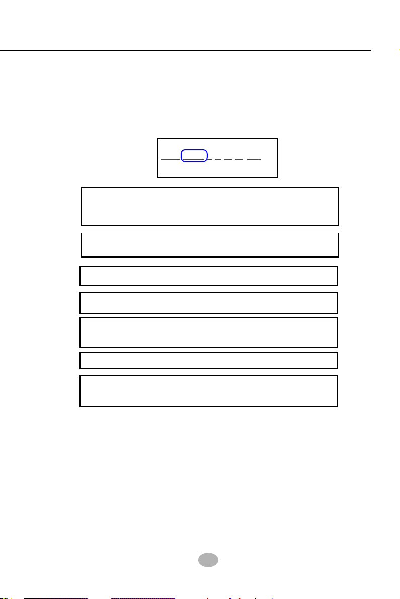
1-2 Mainboard Specification Table
K8AV-R Specifications and Features
CPU Socket 754 for AMD Athlon 64
North Bridge
South Bridge
BIOS
Memory
I/O Chip
AGP interface
Audio
IDE Interface
RAID Interface
LAN Interface
PCI Slots
I/O Connectors
Other common
features
VIA K8T800, supporting 800 MHz FSB
VT8235 CD
AWARD BIOS
Supporting DDR 400/333/266 SDRAM, up to
2GB in 2 DIMM slots
ITE IT8705F, with Hardware Monitor
AGP8X/4X Mode only; 1 AGP Slot on board
AC’97 Audio 2.2 compliant, 6-channel audio
2 PATA 133/100 IDE ports; 1 PATA / PATA RAID
133 IDE port supported by PDC20378
PDC20378 supporting 2 SATA RAID connectors
and 1 PATA RAID IDE connector
Not Integrated on board
5 PCI Master slots on board
6 USB V2.0, 1 FDD port, 2 COM ports, 1 LPT, 1
IrDA, 1 PS/2 K/B, 1 PS/2 Mouse
Keyboard/Mouse Wake Up
10
Page 8
Chapter 1 Specification
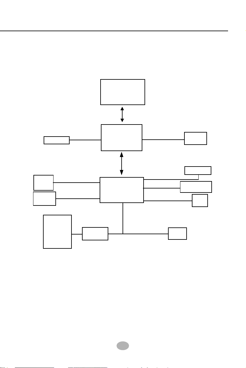
1-3 Chipset System Block Diagram
Athlon 64
Processors
HyperTransport interface
DDR memory
Interface
DDR 400/333/
System
Memory
AGP Slot
800MHz
North Bridge
AGP 8X/4X
VIA K8T800
266
8X V-Link
5 PCI Slots
Audio Codec
(6-channel)
BIOS
4 IDE
Devices
Mouse
Keyboard
IR
FDD
Serial Ports
Printer Port
Game/MIDI
H/Monitor
ATA 133/100/66
LPC I/O
IT8705
South Bridge
VIA VT8235CD
PCI Bus
AC’97
USB Bus V2.0
Athlon 64 + VIA K8T800 + VIA VT8235 CD Diagram
USB
Ports
11
Page 9

K8AV-R
1-4 Mainboard Specifications
1-4.1 CPU Socket
CPU Socket 754 on board, supporting AMD Athlon 64 CPU with 800MHz
System Bus
1-4.2 System Chipsets
• North Bridge VIA K8T800 for managing and supporting 800MHz
system Bus, AGP 8X/4X interface and DDR 400/333/266MHz Memory
Interface.
• South Bridge VIA VT8235 CD working with North Bridge K8T800
supporting the V-Link, LPC Super I/O, PCI interface, ATA133 interface,
USB V2.0 interface, as well as AC’97 Audio 6-channel interface.
1-4.3 Memory
2 DDR DIMM 184-pin slots on board :
• Supporting DDR 400/333/266 SDRAM up to 2GBs
• Supporting installation of mixed volumes yet same type of DDR
SDRAM modules
1-4.4 BIOS
• Supporting Plug & Play V1.0
• Flash Memory for easy upgrade
• Supporting BIOS Writing Protection and Year 2000 compliant
• Supporting BIOS Setup (See Chapter 4 BIOS Setup)
1-4.5 Accelerated Graphics Port (AGP) Interface
AGP Controller embedded on board, supporting:
• 1.5V(8X/4X) power mode only, 1 AGP Slot supported
• 8X 66MHz AD and SBA signaling; AGP pipelined split-transaction
longburst transfers up to 2GB/sec.
• AGP 8X/4X supported, AGP V3.0 compliant
12
Page 10

Chapter 1 Specification
1-4.6 Advanced System Power Management
Advanced Configuration and Power Interface incorporated in BIOS for
reducing power consumption :
• ACPI 1.0 compliant (Advanced Configuration and Power Interface)
• APM V1.2 compliant (Legacy Power Management)
• ACPI Suspend function supported
• Keyboard/Mouse Power On/Wake Up
• USB Wake-up supported by the optional STR(Suspend To RAM) func-
tion
• Real Time Clock with date alarm, month alarm, and century field
1-4.7 Multi-I/O Functions
• PCI EIDE Controller, supporting:
-- 2 ATA 133 / 100 / 66 IDE connectors supporting up to 4 IDE devices;
• Promise RAID Controller PDC20378, supporting:
-- 1 PATA/PATA RAID 133 IDE connector supporting 2 IDE/RAID IDE
HDDs
-- 2 SATA RAID 150Mb Connectors supporting 2 SATA RAID HDDs
• Dedicated IR Functions:
-- 1x5 IR connector dedicated to IR function with Infrared-IrDA (HPSIR)
and ASK (Amplitude Shift Keyed) IR
• Multi-mode parallel data transfer:
-- Standard mode, high speed mode ECP and enhanced mode EPP
• Floppy Drive Connector:
-- 1 FDD connector supporting 2 floppy drives with drive swap support
• Universal Serial Bus Transfer Mode:
-- USB V2.0 compliant, 480Mb/s USB Bus, supporting Windows 98 and
later operating systems; USB drivers provided in Support CD for installa tion
-- 2 built-in USB connectors and 2 more USB pin-headers which require 2
optional USB cables to provide 4 more USB ports
• PS/2 Keyboard and PS/2 Mouse
• UARTs (Universal Asynchronous Receiver / Transmitter):
-- 2 complete serial ports (COM1 & COM2) on board
1-4.8 Expansion Slots
• 5 PCI Bus Master slots
• 1 AGP 8X/4X slot
• 2 DDR DIMM slots
13
Page 11

K8AV-R
1-4.9 AC’97 Audio Codec on board
AC’97 Audio Codec on board, 6-channel playback compliant
• Supporting 6-channel playback of PCM audio output
• 6 channel audio consists of Front Left, Front Right, Back Left, Back
Right, Center and Subwoofer for complete surround sound effect.
• AC’97 Audio Codec Driver enclosed in Support CD for user’s
installation
1-4.10 Hardware Monitor on board
• Hardware Monitor integrated in LPC I/O IT8705F, providing monitoring functions on hardware voltage, temperatures and fan speeds.
• Utility Software Soltek Hardware Monitor for displaying monitor status is enclosed in Support CD for user’s installation.
1-4.11 Form Factor
• ATX Form Factor, ATX Power Supply
• Mainboard size: 305mm x 220mm
14
Page 12

Chapter 1 Specification
MEMO
15
Page 13

K8AV-R
Chapter 2 Hardware Setup
To Get Things Ready for Hardware Setup !
1. We recommend to install your CPU before any other components.
For detailed installation instructions of processor, you can also refer
to the pamphlet enclosed in your CPU package.
2. Installing a cooling fan with a good heatsink is a must for proper heat
dissipation for your CPU. Get ready an appropriate fan with heatsink
for proper installation. Improper fan and installation will damage your
CPU.
3. In case CPU Vcore, CPU clock or Frequency Ratio is adjustable on
board, please follow the instructions described in the User Manual
for proper setup. Incorrect setting will cause damage to your CPU.
The following topics are included in this chapter:
2-1 CPU Identification and Installation
2-2 Memory Installation
2-3 AGP Slot Installation
2-4 IDE Connector Installation
2-5 Floppy Drive Connector ( FDC ) Installation
2-6 ATX Power Supply Installation
2-7 Jumper Settings
2-8 Other Connectors Configuration
16
Page 14
Chapter 2 Hardware Setup
2-1 CPU Identification and Installation
2-1.1 CPU Identification Legends
AMD Athlon 64
ADA 3100 A E P 5 AO
(1) (2) (3) (4) (5) (6) (7)
Family / Architecture:
(1)
ADA=AMD Athlon 64 Desktop Processor
Speed: 3100=1800MHz, 3400=2000MHz
(2)
Package Type: A=754 Pin Lidded OuPGA
(3)
Voltage: E=1.5V
(4)
(5)
Maximum Temperature: P=70˚C
Size of L2 Cache: 5=1 Megabyte
(6)
Part Definition: AO=CPUID Model 4, P-state transition
(7)
support
17
Page 15

K8AV-R
Socket 754
Pin 1
Socket 754
N
AMD Athlon
Pin 1
2-1.2 CPU Installation with Socket 754
This mainboard is built with CPU Socket 754 supporting the AMD Athlon
64:
• Follow the steps described in this section to install CPU into the onboard Socket 754.
• After installation of CPU, you must also install a proper cooling fan
on top of the CPU and connect the Fan cable to the CPU fan
connector.
1. First pull sideways the lever of
Socket 754, and then turn it up
900 so as to raise the upper layer
of the socket from the lower
platform.
2. Configure Pin 1 of CPU to Pin 1
of the Socket, just as the way
shown in the diagram on the
right. Adjust the position of CPU
until you can feel all CPU pins
get into the pin holes of the
socket.
3. Make sure that all CPU pins have
completely entered the socket
and then lower down the lever
to lock up CPU to socket.
Pin 1
Socket 754
AMD Athlon
N
18
Page 16

Chapter 2 Hardware Setup
184-Pin DIMM Notch Key Definitions
DRAM Key Position Voltage Key Position
2-2 Memory Installation
How to tackle the memory Modules:
• Make sure to unplug your power supply before adding or removing
memory module. Failure to do so may cause severe damage to both
your mainboard and the memory module.
• Pay attention to the orientation of the DIMM slots. Forcing a DIMM
into a slot improperly will damage the memory module and slot itself.
• Make sure you have the right type of memory module for your
mainboard.
2-2.1 To Install DDR SDRAM Module
• This mainboard supports up to 2GB DDR 400/333/266 SDRAM, with
2 DDR DIMM slots on board. Do not insert other type of modules into
these slots.
• DDR DIMM slot has 184-pins and one notch. Insert a DDR SDRAM
vertically into the 184-pin slot with the notch-to-rib matching.
(2.5V Voltage Key)DDR Notch
2-2.2 To Remove a DIMM
Press down the holding latches on both sides of slot to release the
module from the DIMM slot.
DDR Rib
Module Latch
19
Page 17

K8AV-R
2-3 AGP Slot Installation
The AGP slot on board supports 1.5V AGP 8X/4X card only. A Rib is
specifically added to the 8X/4X slot so as to match the AGP 8X/4X card.
To insert a 3.3V AGP 2X card into the AGP 4X slot will damage the
system chip and burn the 1.5V circuitry.
An AGP 8X card will support a data transfer rate up to 2GB/sec., while
an AGP 4X card will provide 1GB/sec transfer rate.
AGP Accelerator
notch
AGP 8X/4X Slot
JKB1
Fan1
Mouse
(on top)
PS/2 K/B
USB0
(on top)
USB1
Line
Line
JAUD1
1
(underside)
COM1
COM2
Out
In
MIC
ALC650
AC'97
Codec
1
(underside)
LPT1
Game/MIDI Port
LPC I/O
IT8705
BIOS
Audio1
CD-In1
1
DIMM2
DDR 400/333/266 MHz
DIMM1
Fan2
ATA2
PDC20378
ATA1
Main Power
1
1
1
IDE1
FD1
IDE2
RT1
Li
Battery
1
JBAT1
1
IDE3
20
-
PWR
PWLED
+
RST
IR
NJ1
-
SPK
LED
+
HDD
1
Socket 754
VIA
+12V Power
JCLK1
1
K8T800
AGP 4X/8X
PCI 1
PCI 2
PCI 3
VIA
VT8235
CD
PCI 4
PCI 5
SCR1
1
WOL1
USB3
USB2
Fan3
1
1
1
20
Page 18

Chapter 2 Hardware Setup
2-4 IDE Connector Installation
To install IDE Connector, you may connect the blue connector of IDE
cable to the primary (IDE1) or secondary (IDE2) connector on board,
and then connect the gray connector to your slave device and the black
connector to your master device. If you install two hard disks, you must
configure the second drive to slave mode by setting its jumpers correctly.
Please refer to your hard disk documentation for the jumper settings.
JKB1
Fan1
(on top)
PS/2 K/B
(on top)
USB1
1
Mouse
USB0
COM1
COM2
Line
Line
In
MIC
JAUD1
Out
Codec
(underside)
ALC650
AC'97
1
(underside)
LPT1
Game/MIDI Port
LPC I/O
IT8705
BIOS
Audio1
CD-In1
1
+12V Power
JCLK1
PCI 1
PCI 2
PCI 3
PCI 4
PCI 5
WOL1
DDR 400/333/266 MHz
Socket 754
VIA
K8T800
AGP 4X/8X
VIA
VT8235
CD
USB3
USB2
1
1
1
ATA IDE connectors:
IDE1
Orient the red line on the IDE
IDE2
Flat Cable to Pin1.
Fan2
Main Power
1
1
1
IDE1
FD1
IDE2
RT1
Li
Battery
1
JBAT1
ATA2
1
IDE3
20
-
PDC20378
PWR
PWLED
+
RST
IR
NJ1
ATA1
-
SPK
Fan3
LED
+
HDD
1
Pin 1 (to Red Line)
DIMM2
DIMM1
1
SCR1
1
Black Connector
(To Master Device)
Red Line
IDE Flat Cable
21
Gray Connector
(To Slave Device)
Blue Connector
(To Mainboard)
Page 19

K8AV-R
2-5 Serial ATA / Parallel ATA RAID Connectors
The Serial ATA is designed to improve the Parallel ATA with the capability of Hot Plug and a data bandwidth of 150Mbytes/second. It also reduce voltage and pin count and can be implemented with thin cables
which improve the inner ventilaton of PC cases.
2 Serial ATA RAID and 1 Parallel ATA RAID connectors are built on
board, supported by the RAID Controller PDC20378.
JKB1
Fan1
Mouse
1
(on top)
(underside)
PS/2 K/B
USB0
(on top)
(underside)
USB1
COM1
LPT1
COM2
Line
Out
Line
In
MIC
Game/MIDI Port
CD-In1
JAUD1
1
1
ALC650
AC'97
Codec
LPC I/O
IT8705
BIOS
Audio1
SCR1
1
1
DIMM2
DIMM1
+12V Power
JCLK1
PCI 1
PCI 2
PCI 3
PCI 4
PCI 5
WOL1
DDR 400/333/266 MHz
Socket 754
VIA
K8T800
AGP 4X/8X
VIA
VT8235
CD
USB3
USB2
1
1
1
Fan2
Main Power
Use ATA1/2 and IDE3 to
1
1
1
IDE1
FD1
IDE2
Li
Battery
1
JBAT1
ATA2
PDC20378
ATA1
Fan3
configure RAID (Disk Array)
RT1
Parallel ATA RAID Connector
IDE3 (for 2 IDE RAID HDD)
1
Serial ATA RAID Connector
IDE3
ATA2
20
-
PWR
PWLED
+
RST
IR
Serial ATA RAID Connector
NJ1
-
SPK
LED
+
HDD
1
ATA1
RAID Controller PDC20378
Serial ATA Hard Disk
SATA Port
Serial ATA Cable
SATA Connector
SATA Power Connector
22
Page 20

Chapter 2 Hardware Setup
2-6 Floppy Drive Connector ( FDC ) Installation
To install FDC, you should connect the end of FDC cable with single
connector to the board, and connect the other end with two connectors
to the floppy drives.
JKB1
Fan1
1
Mouse
(on top)
PS/2 K/B
USB0
(on top)
USB1
Line
Line
MIC
JAUD1
(underside)
COM1
COM2
Out
In
ALC650
AC'97
Codec
1
(underside)
LPT1
Game/MIDI Port
LPC I/O
IT8705
BIOS
Audio1
CD-In1
1
DIMM2
DDR 400/333/266 MHz
DIMM1
Fan2
Floppy Drive Connector:
Orient the red line of the
Floppy Flat Cable to Pin1.
ATA2
PDC20378
ATA1
Main Power
1
1
1
IDE1
FD1
IDE2
RT1
Pin 1 (to Red Line)
1
IDE3
20
-
PWR
PWLED
+
RST
IR
NJ1
-
SPK
LED
+
HDD
1
Battery
1
Li
JBAT1
Socket 754
VIA
+12V Power
JCLK1
1
K8T800
AGP 4X/8X
PCI 1
PCI 2
PCI 3
VIA
VT8235
CD
PCI 4
PCI 5
SCR1
1
WOL1
USB3
USB2
Fan3
1
1
1
Signal Swap End
To 1st Floppy Drive
To 2nd Floppy Drive
Red line
FDD Cable
23
To mainboard
Page 21

K8AV-R
2-7 ATX Power Supply Installation
+12V Power Connector
24
GND
+12V
GND
+12V
13
JKB1
Fan1
Mouse
1
(on top)
(underside)
PS/2 K/B
USB0
(on top)
(underside)
USB1
COM1
LPT1
COM2
Line
Out
Line
In
MIC
Game/MIDI Port
CD-In1
JAUD1
1
1
ALC650
AC'97
Codec
LPC I/O
IT8705
BIOS
Audio1
SCR1
1
1
DIMM2
DIMM1
+12V Power
JCLK1
PCI 1
PCI 2
PCI 3
PCI 4
PCI 5
WOL1
DDR 400/333/266 MHz
Socket 754
VIA
K8T800
AGP 4X/8X
VIA
VT8235
CD
USB3
USB2
1
1
1
Fan2
Main Power
1
1
1
IDE1
FD1
IDE2
RT1
Li
Battery
1
JBAT1
ATA2
1
IDE3
20
-
PDC20378
PWR
PWLED
+
RST
IR
NJ1
ATA1
-
SPK
LED
Fan3
+
HDD
1
+12V
5SB
PWR OK
GND
+5V
GND
+5V
GND
+3.3V
+3.3V +3.3V
Pin1 Pin11
Main Power Connector
(20-pin)
+5V
+5V
-5V
GND
GND
GND
PS ON#
GND
-12V
ATX V2.03 Power Supply is strongly recommended for mainboard running with Athlon 64 processors.
To set up Power Supply on this mainboard:
1. Connect the on-board Main Power Connector (20-pin) to the Main
Power Connector (20-pin) of an ATX Power Supply which can be of
the latest version 2.03 model, and then connect the square-shaped
+12V Power Connector on board to the square-shaped +12V Power
Connector of the Power Supply.
Warning: Both the Main Power Connector and the +12V Power
Connector should be connected to Power Supply; otherwise, the
system may either not start or be damaged.
24
Page 22

Chapter 2 Hardware Setup
2-8 Jumper Settings
The following diagrams show the locations and settings of jumper / switch
blocks on the mainboard.
KB/Mouse Power On / Wake Up
JKB1
1-2 closed (Default)
1
1
JKB1
Fan1
Mouse
1
(on top)
DIMM2
(underside)
PS/2 K/B
USB0
(on top)
(underside)
USB1
DIMM1
COM1
LPT1
COM2
Line
Out
Line
In
MIC
Game/MIDI Port
+12V Power
CD-In1
JAUD1
1
JCLK1
1
ALC650
AC'97
Codec
BIOS
1
PCI 1
PCI 2
LPC I/O
PCI 3
IT8705
PCI 4
PCI 5
Audio1
SCR1
1
WOL1
Enabled
2-3 closed
Disabled
DDR 400/333/266 MHz
Socket 754
VIA
K8T800
AGP 4X/8X
VIA
VT8235
CD
USB3
USB2
1
1
1
Fan2
Main Power
1
1
1
1
IDE1
IDE2
RT1
Li
Battery
1
JBAT1
ATA2
PDC20378
NJ1
ATA1
Fan3
1
FD1
1
IDE3
20
-
PWR
PWLED
+
RST
IR
-
SPK
LED
+
HDD
1
JBAT1
Clear CMOS
(default)
1-2 closed
To hold data
2-3 closed
To clear CMOS
(default)
200MHz
7-8 closed
1357
JCLK1:
CPU Clock Select
233MHz
3-4 closed
266MHz 270MHz
1-2 closed
1357 1357
25
1-2 closed
3-4 closed
1357
Page 23

K8AV-R
2-8.1 How to tackle the Jumpers:
123
A 3-pin Jumper
If a pin-header (of 2 or more pins) is
designed in such a way that its pins
can be closed or linked together to
set up a specific function,
is called a jumper in this manual.
this header
A 2-pin
Jumper
Cap
The conductor inside the cap
links two header-pins together.
• A Jumper is usually but not necessarily given a “JpX” legend.
• In the Jumper setting diagram, all jumper pins covered with
black marks stand for closed pins with jumper cap.
1 13313
Jp X
Jumper with
Pin 2-3 closed
Jumper with
all pins open
Jumper with
Pin 1-2 closed
• Do not remove any jumper cap when power is on. Always
make sure the power is off before changing any jumper settings.
Otherwise, mainboard could be damaged.
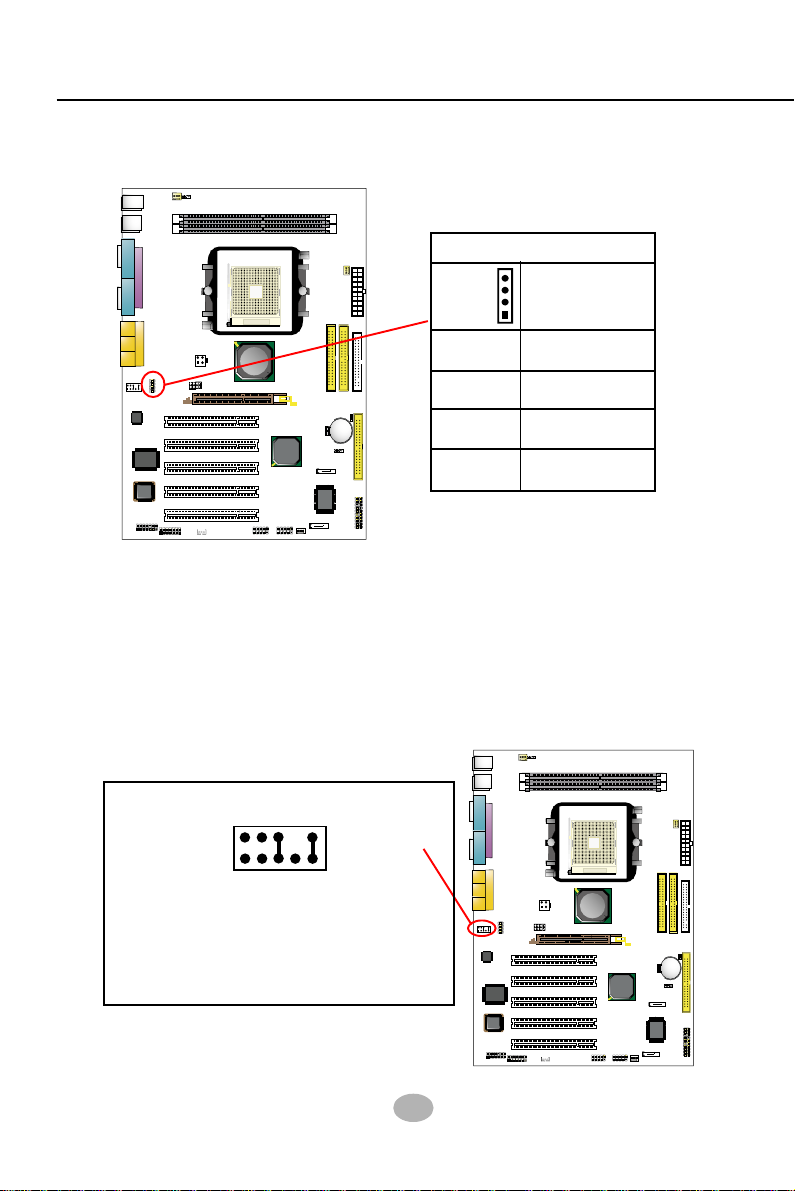
2-8.2 JCLK1: CPU Clock Select
JCLK1 is designed on board as an 8-pin jumper for CPU clock select.
1. Select the CPU clock you want from 200/233/266/270MHz and set
JCLK1 to match your choice.
2. If you select a CPU clock which is higher than your default CPU
clock, it may fail to boot system. You should restore the default setting
and then clear CMOS to reboot your system. (See Clear CMOS in
next paragraph.)
(default)
200MHz
7-8 closed
1357
JCLK1:
CPU Clock Select
233MHz
3-4 closed
1357 1357
266MHz 270MHz
1-2 closed
26
1-2 closed
3-4 closed
1357
Page 24

Chapter 2 Hardware Setup
Further notes on CPU Overclocking:
1. If you have successfully booted system with or without CPU overclock,
you still can do another CPU overclock in BIOS Setup. Please enter
BIOS Setup, choose “Frequency/Voltage Control” menu, and take
the “Use Linear” option of the “Use CPU Linear Frequency”. Then
configure the “CPU Clock” item to raise your CPU clock.
2. CPU overclocking should take all components on board into account.
If you fail in BIOS overclocking, you will not be able to restart system.
In such case, power off system and clear CMOS by JBAT1 as stated
below and then restart your system. And remember to reconfigure
whatever should be reconfigured.
3. If your system is already fixed in a cabinet or case, you may not like
to take the trouble to clear CMOS. Then power on your system with
the power button on the case and simultaneously press down the
“Insert” key of the keyboard until you see the initial bootup screen
appear. And remember you should also enter CMOS BIOS Setup
and choose “Load Optimized Defaults” to restore default BIOS .
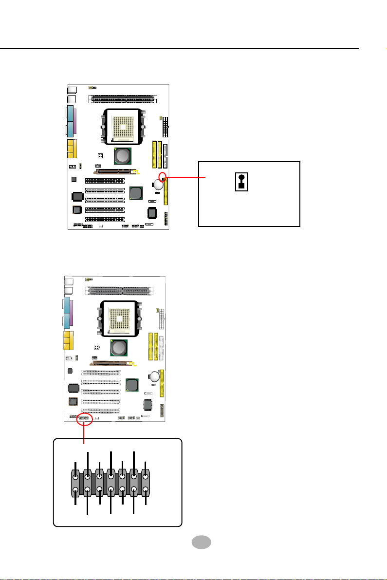
2-8.3 JBAT1: Clear CMOS
When you have problem with rebooting your system, you can clear
CMOS data and restore it to default value. To clear CMOS with Jumper
JBAT1, please follow the steps below:
1. Power off system.
2. Set JBAT1 to Pin 2-3 closed.
3. After 2 or 3 seconds, return the JBAT1 setting to Pin1-2 closed.
4. CMOS data are restored to default. Remember never clear CMOS
when system power is on.
1
1
JBAT1
Clear CMOS
(default)
1-2 closed
To hold data
2-3 closed
To clear CMOS
27
Page 25

K8AV-R
2-8.4 JKB1: Keyboard/Mouse Power On/Wake Up
JKB1 is designed on board as a jumper to enable/disable the PS/2 keyboard/mouse Power On/Wake Up from system off or suspend mode.
Yet users should still enter BIOS setup to choose the Wake Up/ Power
On mode.
USB keyboard/mouse Wake Up function is an optional function in this
mainboard.
KB/Mouse Power On / Wake Up
1
1
JKB1
1-2 closed (Default)
Enabled
2-3 closed
Disabled
28
Page 26
Chapter 2 Hardware Setup
2-9 Other Connectors Configuration
This section lists out all connectors configurations for users’ reference.
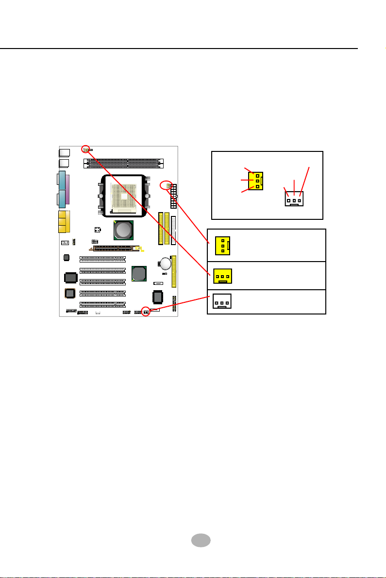
2-9.1 On-board FAN Connectors
JKB1
Fan1
Mouse
1
(on top)
(underside)
PS/2 K/B
USB0
(on top)
(underside)
USB1
COM1
LPT1
COM2
Line
Out
Line
In
MIC
Game/MIDI Port
CD-In1
JAUD1
1
1
ALC650
AC'97
Codec
LPC I/O
IT8705
BIOS
Audio1
SCR1
1
1
DIMM2
DIMM1
+12V Power
JCLK1
PCI 1
PCI 2
PCI 3
PCI 4
PCI 5
WOL1
DDR 400/333/266 MHz
Socket 754
VIA
K8T800
AGP 4X/8X
VIA
VT8235
CD
USB3
USB2
1
1
1
Sensor
Fan2
+12V
GND
Void
+12V
GND
Main Power
1
1
1
IDE1
FD1
IDE2
RT1
Li
Battery
1
JBAT1
ATA2
1
IDE3
20
-
PDC20378
PWR
PWLED
+
RST
IR
NJ1
ATA1
-
SPK
LED
Fan3
+
HDD
1
Sensor Conn.
FAN2, Sensor Fan Connector
(Yellow)
FAN1, Sensor Fan Connector
(Yellow)
No Sensor
FAN3, No-sensor Fan Connector
Both Sensor and No-sensor Fan Connectors support CPU/AGP/System/Case cooling fan with +12V mode. When connecting the wire to
any Fan Connector, user should make sure that the red wire is for the
positive current and should be connected to pin +12V, and the black
wire is Ground and should be connected to pin GND. A Hardware Monitor chipset is on board, with which user can install a Hardware Monitor
Utility and read the fan speed transmitted from the sensor fan connector.
Otherwise, user can read the fan speed from the “Hardware Monitor
Status” in CMOS BIOS.
A running fan will send out 2 electric pulses per rotation of its fan
blade to a Sensor Fan Connector which in turn will count the electric
pulses and send the information to the System Hardware Monitor. The
hardware Monitor Program will work out the fan rotation speed and display it on screen.
29
Page 27
K8AV-R
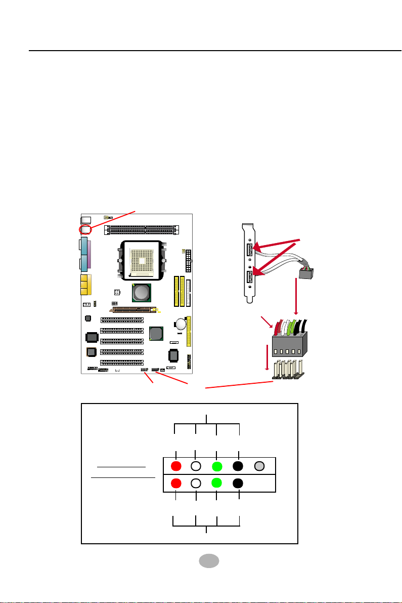
2-9.2 USB Ports and USB Pin-headers
This mainboard provides two USB ports USB0 and USB1 on board
supporting various USB devices. In addition, two USB pin-headers are
added on board to provide expansion of four more optional USB ports
by using two additional USB Cables. User can order the optional USB
cables from your mainboard dealer or vender.
When plugging the USB cable to USB Header, user must make sure
the red wire is connected to Pin 1.
All 6 USB ports are compliant with 1.0 / 2.0 USB Bus. USB 2.0 supports Windows 98 and above. USB 1.0 / 2.0 drivers are provided in
Support CD for user’s installation.
USB connectors USB0 and USB1 (underside)
JKB1
Fan1
Mouse
1
(on top)
(underside)
PS/2 K/B
USB0
(on top)
(underside)
USB1
COM1
LPT1
COM2
Line
Out
Line
In
MIC
Game/MIDI Port
CD-In1
JAUD1
1
1
ALC650
AC'97
Codec
LPC I/O
IT8705
BIOS
Audio1
1
1
DDR 400/333/266 MHz
DIMM2
DIMM1
Fan2
Socket 754
VIA
K8T800
+12V Power
JCLK1
AGP 4X/8X
PCI 1
PCI 2
PCI 3
PCI 4
PCI 5
SCR1
WOL1
VIA
VT8235
USB3
USB2
1
1
1
Main Power
1
1
1
IDE1
FD1
IDE2
RT1
Li
Battery
1
JBAT1
CD
ATA2
1
IDE3
20
-
PDC20378
PWR
PWLED
+
RST
IR
NJ1
ATA1
-
SPK
LED
Fan3
+
HDD
1
USB Pin-headers USB2 and USB3
USB Cable (Optional)
USB Port
Red wire
1
10
1
10
First USB Port Wiring for Front USB
USB Header
Pin Assignment
Second USB Port Wiring for Front USB
Red White
+5V
1
+5V
Red
D1-
D2-
White
Green
Green
30
D1+
D2+
black
GND
GND
black
10
Page 28

Chapter 2 Hardware Setup
2-9.3 Chassis Panel Connectors
A.
B. C. D.
E. F. G. H. I. J. K.
A : PS/2 Mouse
B : Port USB 0
C : Printer PORT
D : Game/MIDI
E : PS/2 Keyboard
F : USB 1 (Underside)
G : COM 1
H : COM 2
I : Line Out / Front Speaker Out
J : Line In / Rear Speaker Out
K : Microphone Input / Center
Subwoofer Out
2-9.4 PS/2 Mouse And PS/2 Keyboard
PS/2 Mouse Connector
6 Void
(green, on top)
5 Mouse Clock
4 VCC
2 Void
6 Void
4 VCC
2 Void
PS/2 Keyboard Connector
3 GND
1 Mouse Data
5 Keyboard Clock
3 GND
1 Keyboard Data
(purple, underside)
31
Page 29
K8AV-R
2-9.5 CD-ROM Audio Connectors (CD-In1)
CD-In1 is an audio connector connecting CD-ROM audio to mainboard.
JKB1
Fan1
Mouse
1
(on top)
(underside)
PS/2 K/B
USB0
(on top)
(underside)
USB1
COM1
LPT1
COM2
Line
Out
Line
In
MIC
Game/MIDI Port
CD-In1
JAUD1
1
1
ALC650
AC'97
Codec
LPC I/O
IT8705
BIOS
Audio1
SCR1
1
1
DIMM2
DIMM1
+12V Power
JCLK1
PCI 1
PCI 2
PCI 3
PCI 4
PCI 5
WOL1
DDR 400/333/266 MHz
Socket 754
VIA
K8T800
AGP 4X/8X
VIA
VT8235
CD
USB3
USB2
1
1
1
Fan2
Main Power
1
1
1
IDE1
FD1
IDE2
RT1
Li
Battery
1
JBAT1
ATA2
1
IDE3
20
-
PDC20378
PWR
PWLED
+
RST
IR
NJ1
ATA1
-
SPK
LED
Fan3
+
HDD
1
CD-In1
Pin 1
Pin 2
Pin 3
Pin 4
1
Pin Signal
Left Channel
GND
GND
Right Channel
CD-ROM Audio Connector
2-9.6 JAUD1: Front Panel Audio Connector (optional)
This Mainboard is designed with a Front Panel Audio connector “JAUD1”
which provides connection to your chassis.
1. When JAUD1 is set to 5-6 closed and 9-10 closed, this default setting
disables this connector and leaves the Back Panel Audio enabled.
2. To use this Front Panel Audio Connector, please open all pins of
JAUD1 and connect it to the Front Panel Audio Connector.
JKB1
Fan1
Mouse
1
JAUD1: Front Audio Connector
2
1
Pin 1 Mic In
Pin 3 Mic VREF
Pin 5 FPOUT R
Pin 7 (Key)
Pin 9 FPOUT L
10
9
Pin 2 Aud GND
Pin 4 Aud Vcc
Pin 6 RET R
Pin 8 (Void)
Pin10 RET L
(on top)
(underside)
PS/2 K/B
USB0
(on top)
(underside)
USB1
COM1
LPT1
COM2
Line
Out
Line
In
MIC
Game/MIDI Port
CD-In1
JAUD1
1
1
ALC650
AC'97
Codec
LPC I/O
IT8705
BIOS
Audio1
1
DDR 400/333/266 MHz
DIMM2
DIMM1
Socket 754
VIA
K8T800
+12V Power
JCLK1
AGP 4X/8X
PCI 1
PCI 2
PCI 3
VT8235
VIA
CD
PCI 4
PCI 5
SCR1
1
WOL1
USB3
USB2
Fan3
1
1
1
ATA1
ATA2
PDC20378
Fan2
Main Power
1
1
1
IDE1
FD1
IDE2
RT1
Li
Battery
1
JBAT1
1
IDE3
20
-
PWR
PWLED
+
RST
IR
NJ1
-
SPK
LED
+
HDD
1
32
Page 30
Chapter 2 Hardware Setup
P
C
I
1
P
C
I
2
P
C
I
3
P
C
I
4
P
C
I
5
IDE1
IDE3
L
i
B
a
t
t
e
r
y
F
a
n
3
V
I
A
V
T
8
2
3
5
FD1
C
O
M
1
MIC
L
i
n
e
O
u
t
L
i
n
e
I
n
G
a
m
e
/
M
I
D
I
P
o
r
t
A
G
P
4
X
/8
X
J
B
A
T
1
U
S
B
3
1
DIMM1
D
D
R
4
0
0
/
3
3
3
/
2
6
6
M
H
z
U
S
B
1
P
S
/
2
K
/
B
Mouse
(
o
n
t
o
p
)
(
u
n
d
e
r
s
i
d
e
)
F
a
n
1
1
J
K
B
1
U
S
B
2
1
RT1
1
C
D
-
I
n
1
A
C
'
9
7
C
o
d
e
c
J
A
U
D
1
L
P
C
I
/
O
I
T
8
7
0
5
B
IO
S
1
1
A
L
C
6
5
0
DIMM2
(
u
n
d
e
r
s
i
d
e
)
(
o
n
t
o
p
)
U
S
B
0
1
1
1
M
a
i
n
P
o
w
e
r
C
O
M
2
L
P
T
1
VIA
K
8
T
8
0
0
IDE2
1
1
F
a
n
2
A
u
d
i
o
1
1
S
o
c
k
e
t 7
5
4
+
1
2
V
P
o
w
e
r
P
D
C
2
0
3
7
8
A
T
A
2
A
T
A
1
W
O
L
1
S
C
R
1
1
J
C
L
K
1
N
J1
H
D
D
I
R
P
W
R
1
2
0
S
P
K
R
S
T
+
-
+
-
P
W
L
E
D
L
E
D
C
D
2-9.7 Thermal Resistor and Connector
JKB1
Fan1
Mouse
1
(on top)
(underside)
PS/2 K/B
USB0
(on top)
(underside)
USB1
COM1
LPT1
COM2
Line
Out
Line
In
MIC
Game/MIDI Port
CD-In1
JAUD1
1
1
ALC650
AC'97
Codec
LPC I/O
IT8705
BIOS
Audio1
1
DDR 400/333/266 MHz
DIMM2
DIMM1
Fan2
Socket 754
VIA
K8T800
+12V Power
JCLK1
AGP 4X/8X
PCI 1
PCI 2
PCI 3
VT8235
PCI 4
PCI 5
SCR1
1
USB2
1
1
1
WOL1
Main Power
1
1
IDE1
FD1
IDE2
RT1
Li
Battery
VIA
1
JBAT1
CD
ATA2
IDE3
PDC20378
PWR
IR
NJ1
ATA1
-
USB3
LED
Fan3
+
HDD
Resistor RT1: A thermal resistor is
mounted by default to connector
RT1 so as to detect the temperature of the system. What RT1 does
is to transmit the thermal signal to
BIOS or Hardware Monitor.
1
RT1
1
20
-
PWLED
+
RST
SPK
1
RT1 is mounted
with Thermal Resistor
by default.
2-9.8 Smart Card Reader Connector
The connector “SCR1” allows you to
use Smart Card Reader. It is compliant with Personal Computer Smart
Card (PC/SC) working group standard
and smart card (ISO 7816) protocols.
LED
8
1
VCC
RFU
SCRIO
SCRRST
SCRFET
NCNCSCRCLK
SCRPRES
RFU
NC
14
7
NC
GND
33
Page 31
K8AV-R
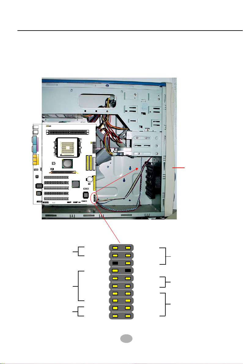
2-9.9 Complex Pin-header (Front Panel Connectors)
This complex Pin-header consists of the following connectors for various front panel supports. When you have fixed the mainboard to the
case, join the connectors of this Complex Pin-header to the case Front
Panel.
JKB1
Fan1
Mouse
1
(on top)
(underside)
PS/2 K/B
USB0
(on top)
(underside)
USB1
COM1
LPT1
COM2
Line
Out
Line
In
MIC
Game/MIDI Port
CD-In1
JAUD1
1
1
ALC650
AC'97
Codec
LPC I/O
IT8705
BIOS
Audio1
1
DDR 400/333/266 MHz
DIMM2
DIMM1
Fan2
Socket 754
VIA
K8T800
+12V Power
JCLK1
AGP 4X/8X
PCI 1
PCI 2
PCI 3
PCI 4
PCI 5
SCR1
1
WOL1
VT8235
USB2
1
1
1
Main Power
1
1
1
IDE1
FD1
IDE2
RT1
Li
Battery
VIA
1
JBAT1
CD
ATA2
1
IDE3
20
-
PDC20378
PWR
PWLED
+
RST
IR
NJ1
ATA1
-
SPK
USB3
LED
Fan3
+
HDD
1
Case
Front Panel
(1)Power Switch
(2)Infrared(IR)
(3)HDD LED
PWRBT#
PWRBT
IR_VCC
NC
IRRX
IRGND
IRTX
HDLEDHDLED+
34
PLEDNC
PLED+
RSTGND
RST1
SP1
NC
SP3
SPVCC
Power LED (4)
Reset Switch (5)
Speaker (6)
Page 32

Chapter 2 Hardware Setup
(1) Power Switch Connector:
Connection: Connected to a momentary button or switch.
Function: Manually switching the system between “On” and “Soft
Off”. Pressing the momentary button for more than 4 seconds will
also turn the system off.
(2) IR Connector (Infrared Connector):
Connection: Connected to Connector IR on board.
Function: Supporting wireless transmitting and receiving module
on board.
(3) HDD LED Connector:
Connection: Connected to HDD LED.
Function: To supply power to HDD LED.
(4) Power LED Connector:
Connection: Connected to System Power LED.
Function: To supply power to “System Power LED”.
(5) Reset Switch Connector:
Connection: Connected to case-mounted “Reset Switch”.
Function: To supply power to “Reset Switch” and support system
reboot function.
(6) Speaker Connector:
Connection: Connected to the case-mounted Speaker.
Function: To supply power to the case-mounted Speaker.
35
Page 33

K8AV-R
Chapter 3 Software Setup
Drivers, Utilities and Software Installation
Support CD:
This mainboard will be shipped with a Support CD which contains those
necessary driver files, Application Softwares and some helpful utilities.
It is a user-friendly, auto-run CD which will open itself up in a CD-ROM
automatically.
This chapter is devoted to describing the installations of all these
essential drivers and utilities on Windows 98SE, Windows ME, Windows 2000 and Windows XP. The installation procedures for all these
operating systems are programed into an auto-run mode. What users
have to do is read and follow the pop-up instructions. We therefore
take the installation on Windows XP as the general illustration hereby.
The priority of driver installation should also be noted. Users are recommended to take the following installation order:
3-1 To Open Support CD
3-2 VIA 4-in-1 Drivers Installation
3-3 AC’97 Audio Driver Installation
3-4 USB 2.0 Driver Installation
3-5 Hardware Monitor Utility Installation
3.6 RAID Driver Installation
36
Page 34

Chapter 3 Software Setup
3-1 To Open Up Support CD:
1. Please put the Support CD enclosed in your mainboard package into
the CD-ROM drive. In a few seconds, the Main Menu will
automatically appear, displaying the contents to be installed for this
series:
2. In case your system does not open the Support CD automatically,
please click to the following path to enter the Main Installation Menu:
D:\ Autorun.exe (assuming that your CD-ROM Drive is Drive D)
3. Users are recommended to install all the drivers and utilities at a
time, though they can be installed separately.
Also, we should take “VIA 4-in-1 Drivers” as first installation priority
to optimize the VIA system.
From next section, we provide detailed descriptions of all these
installations with graphical illustrations.
37
Page 35
K8AV-R
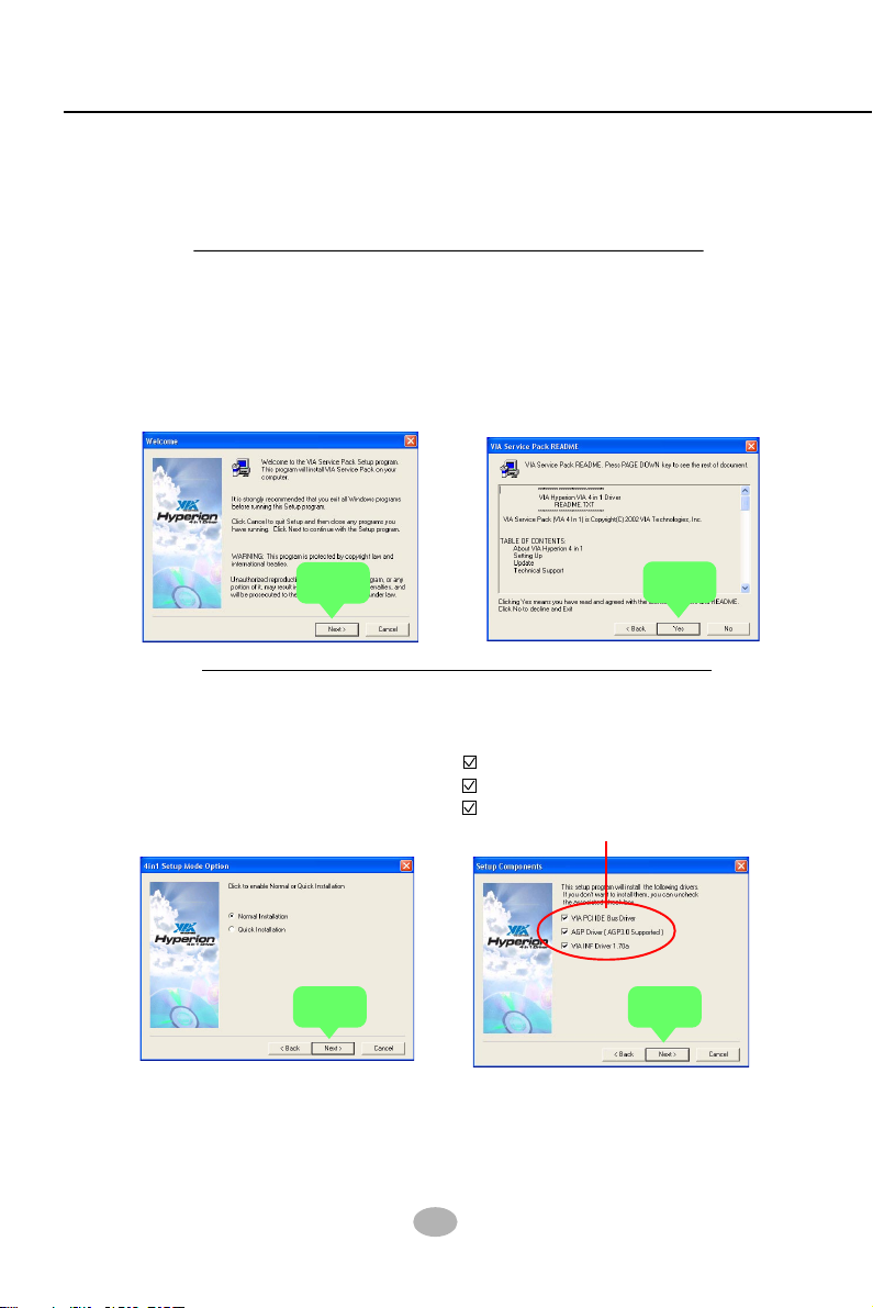
3-2 To Install VIA 4-IN-1 Drivers
1. Following the procedures of opening the Support CD, click to “ VIA 4-
in-1 Drivers” to proceed.
2.The VIA Service Pack
InstallShield Wizard will pop up
to guide you to the VIA Service
pack installation. Click “Next”
button to continue.
Next
4. On the screen below, check
”Normally Install” and click
“Next” to continue. (If you
check “Quick Install”, you will
skip the detailed procedures of
the VIA 4-in-1 Setup.)
3. “VIA Service Pack README”
screen will appear, please click
the “Yes” button to agree with
the Licence Agreement and
continue.
Ye s
5. Select the checkbox as below
and click “Next” to continue:
VIA PCI IDE Bus Driver
AGP Driver (AGP 3.0 Supported)
VIA INF Driver 1.70a
Next
Next
38
Page 36
Chapter 3 Software Setup
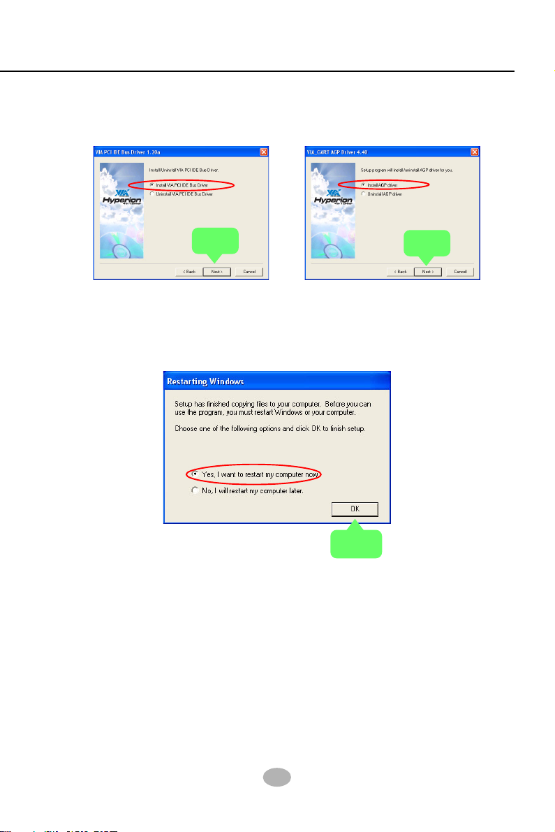
6. Select “Install VIA PCI IDE
Driver” checkbox, then click the
“Next” button to continue.
Next
8. After all these setup procedures have finished, you should restart
your computer by clicking on “OK” so as to put VIA 4-in-1drivers
into effect and proceed to next driver installation.
7. Select “Install VIA AGP Driver”
in turbo mode and press “Next”
button to continue.
Next
39
OK
Page 37

K8AV-R
3-5 AC’97 Audio Driver Installation
Avance AC97 Audio Codec on board, AC’97 2.2 compatible stereo audio
code for PC multimedia systems. Avance AC’97 Audio Codec Driver is provided in Support CD for user’s installation.
3-5.1 Installing AC’97 6-channel Audio Driver
1. Following the procedures of opening the Support CD, click to “ AC’97
Audio Driver” to proceed.
2. Instantly, the “installShield
Wizard” screen appears to
guide you through the “Avance
AC’97 Audio Setup””.
Next
3. instantly, the Setup program
proceeds to install the softwares
which include AC’97 driver and
AVRack. (If you want to stop
setup, click the “Cancel”
button.)
4. After the setup process is
finished, please check the radial
button “Yes, I want to restart my
computer now.” And click
“Finish” to restart your system.
Finish
40
Page 38

Chapter 3 Software Setup
3-3.2 To verify 6-channel Audio
After installation of AC’97 6-channel Codec, you must configure the 5.
1 Speaker connection to enable the 6-channel audio.
1. Connect your on-board Audio Connector to your 6-channel speakers
as depicted in the figure below:
Pale Green Connector
to Front Speaker
Pale Blue Connector
to Rear Speaker
2. After Connection is done, start
your Windows system and
double click “volume” icon at
the taskbar to enter 6-channel
configuration:
3. The AC’97 Audio
Configuration” screen will
pop out. Clikc the
“Speaker Configuration”
bar with your mouse.
Pale Pink Connector to
Center/Subwoofer Speaker
“Volume” icon
41
Page 39

K8AV-R
4. Instantly, the “Speaker Configuration” screen will pop out. Pick the
items “6-channel mode for 5.1 speakers output” and “ Synchronize
the phonejack switch with the speakers settings” and then click “OK”
to finish configuration.
5. At finishing the Speakers Configuration, you can also click the
“Speaker Test” bar on the screen to test the 6-channel performance.
The figure below is the “Speaker Test” screen with testing instructions
enclosed on it. Follow the instructions to perform the Speakers Test.
42
Page 40

Chapter 3 Software Setup
3-4 To Install USB 2.0 Driver
VIA USB V2.0 is already integrated on board. Its 480Mb/s transfer rate
supports operating systems Windows 98SE/Me/2000/XP. USB Driver
installation procedures are of similar steps in these systems. Before
installing VIA USB V2.0 Driver on Windows XP, users should install the
latest Service Pack for Windows XP. Please take the following illustrations from Windows XP as the USB driver installation guide:
1. Update Windows XP with the latest service pack before installing
VIA USB V2.0 Driver.
2. Following the procedures of opening the Support CD, click to choose
“VIA USB 2.0 Driver” to proceed. Please notice that the USB card
driver is different from the USB 2.0 driver typically for the on-board
USB. Do not use the USB card driver here.
3. Instantly the “USB 2.0 Setup Program” will pop up on screen. Click
“Next” to continue.
43
Next
Page 41

K8AV-R
3. Instantly, next screen will pop up to prompt you to select component.
Select “Install USB Driver” and click “Next” button to continue.
Next
4. The USB 2.0 Setup Program will then guide you through the whole
driver setup until the “Finish” screen appears to prompt you to restart
your system. Please click “Finish” button to restart system to put the
new driver into effect.
44
Finish
Page 42

Chapter 3 Software Setup
3-5 To Install Hardware Monitor Utility
3-5.1 Installation
Hardware Monitor is built on this mainboard. Its installation is pro-
grammed to a fully automated mode on Windows 9X/Me/NT4/2000/
XP. Users can follow the model installation below for its installation
on various Windows System.
1.Following the procedures of opening the Support CD, click to “
Hardware Monitor Utility” to proceed.
2. The Soltek Hardware
Monitor InstallShield
Wizard will pop up to guide
you to the Intel Service pack
installation. Press “Next”
button to continue.
3. The InstallShield Wizard
screen will show the current
setting, please click the
“Install” button to continue.
Next
4. After all the setup process
is finished, click “Finish” to
exit the wizard.
Install
Finish
45
Page 43

K8AV-R
3-5.2 Verification
1. After installing Soltek Hardware Monitor, double click “SoltekHM”
icon on the desktop to open the main window of the Soltek HM.
Soltek Hardware
Monitor Icon
2.Instantly, the pop-up screen will show all information about CPU
Temperature, Fan Speed and various Voltages.
Showing the Fan Speed(s) that
Showing the temperature(s), the
function of which is supported by
the mainboard.
is supported by the mainboard.
Click on “Soltek” button to
display the function menu.
Showing the Voltage(s) that is
supported by the mainboard.
Status Warning LED
*Note: Not all items or functions showing in the above picture will
show up. Only those items or functions that are supported
by the mainboard will reveal themselves in the above
screen.
46
Page 44

Chapter 3 Software Setup
3-6 RAID Driver Installation
1. RAID Driver should be intalled into a RAID system. That is, user
should first configure a RAID system and then install the RAID driver
into it.
2. Chapter 5 of this User Manual introduces the configuration of RAID
system and then the installation of RAID Driver. Please refer to
Chapter 5 for the RAID Driver installation.
47
Page 45

K8AV-R
Chapter 4 BIOS Setup
THE BIOS
BIOS stands for Basic Input and Output System. It was once called
ROM BIOS when it was stored in a Read-Only Memory(ROM) chip Now
manufacturers would like to store BIOS in EEPROM which means
Electrically Erasable Programmable Memory. BIOS used in this series
of mainboard is stored in EEPROM, and is the first program to run when
you turn on your computer.
BIOS performs the following functions:
1. Initializing and testing hardware in your computer (a process called
“POST”, for Power On Self Test).
2. Loading and running your operating system.
3. Helping your operating system and application programs manage
your PC hardware by means of a set of routines called BIOS RunTime Service.
This Chapter includes the following topics :
4-1 About BIOS Setup
4-2 To run BIOS Setup
4-3 About CMOS
4-4 The POST (Power On Self Test)
4-5 To upgrade BIOS
4-6 BIOS Setup
48
Page 46

Chapter 4 BIOS Setup
4-1 About BIOS Setup
BIOS setup is an interactive BIOS program that you need to run when:
1. Changing the hardware of your system. (For example: installing a
new Hard Disk etc.)
2. Modifying the behavior of your computer. (For example: changing
the system time or date, or turning special features on or off etc.)
3. Enhancing your computer’s behavior. (For example: speeding up
performance by turning on shadowing or cache)
4-2 To Run BIOS Setup
First access BIOS setup menu by pressing < DEL > key after “POST” is
complete ( before OS is loaded ). BIOS will then display the following
message:
Press “DEL” to enter “SETUP”
4-3 About CMOS
CMOS is the memory maintained by a battery. CMOS is used to store
the BIOS settings you have selected in BIOS Setup. CMOS also
maintains the internal clock. Every time you turn on your computer, the
BIOS Looks into CMOS for the settings you have selected and configures
your computer accordingly. If the battery runs out of power, the CMOS
data will be lost and POST will issue a “CMOS invalid” or “CMOS
checksum invalid” message. If this happens, you have to replace the
battery and do some proper settings in BIOS Setup.
4-4 The POST ( Power On Self Test )
POST is an acronym for Power On Self Test. This program will test all
things the BIOS does before the operating system is started. Each of
POST routines is assigned a POST code, a unique number which is
sent to I/O port 080h before the routine is executed.
49
Page 47

K8AV-R
4-5 To Upgrade BIOS
• System BIOS is incorporated into a Flash memory component. Flash
BIOS allows user to upgrade BIOS without the need to replace an EPROM
component.
• The Upgrade Utility can be loaded on a floppy diskette to execute saving,
verifying, and updating the system BIOS. The Upgrade Utility can also be
run from a hard disk drive or a network drive.
4-5.1 Before Upgrading BIOS
• It is highly recommended that you save a copy of the original mainboard
BIOS along with a Flash EPROM Programming utility (AWDFLASH.EXE)
to a bootable floppy disk so that you can reinstall the BIOS when needed.
4-5.2 Upgrade Process
• Normally, to upgrade BIOS is unnecessary if the system is working fine
Users should only upgrade the BIOS when you experience incompatible
problems or need to create new features.
• “AWDFLASH.EXE” is a Flash EPROM Programming utility that up dates
the BIOS by uploading a new BIOS file to the programmable flash ROM
on the mainboard. This program only works in DOS environment, the
utility can not be executed in Windows 95/98, ME, NT, WINDOWS
2000 or Windows XP environment.
• Please follow the steps below for upgrading the system BIOS:
Step 1. Please visit the board maker’s website, download the zip file
which contains the latest BIOS file and Award Flash Utility “AWDFLASH.
EXE”. After unzipping, the BIOS file format will be *.bin, of which “ * ”
stands for the specific BIOS file name.
Step 2. Create a bootable diskette. Then copy the BIOS file and Award
Flash Utility “AWDFLASH.EXE” into the diskette.
Step 3. Insert the diskette into drive A, reboot your system and boot
from the diskette.
50
Page 48

Chapter 4 BIOS Setup
Step 4. Type awdflash *.bin /sn/py/cc and then press <Enter> to run
BIOS upgrade program. (*.bin depends on your mainboard model and
version code. Instead of typing “*”, you should type specific file name
for your specific mainboard).
Step 5. Please press <F1> or <F10> to exit or reset your system.
Warning ! If the message “ Write Fail ” appears while Award “FLASH
MEMORY WRITER” is verifying Flash memory, just repeat the process.
Please DO NOT reset or turn off the system. If the award memory flash
utility is not able to update the BIOS successfully, your system may not
be able to boot up.
Step 6. You will need a message “CMOS checksum error-Default
loaded” during booting the system. Press <Del> to run CMOS setup
utility, then reload “LOAD SETUP DEFAULTS” or “Load Optimized
Defaults” and save this change.
The parameters of AWDFLASH.EXE
/sn: No original BIOS backup
/py: Program flash memory
/cc: Clear CMOS data (and update data automatically) after pro gramming
NOTE: Users can type AWDFLASH /? to get further details about
the parameters. Incorrect usage of the parameter will damage the BIOS information, so we strongly recommend users
to leave parameters alone unless you fully understand their
function.
51
Page 49
K8AV-R
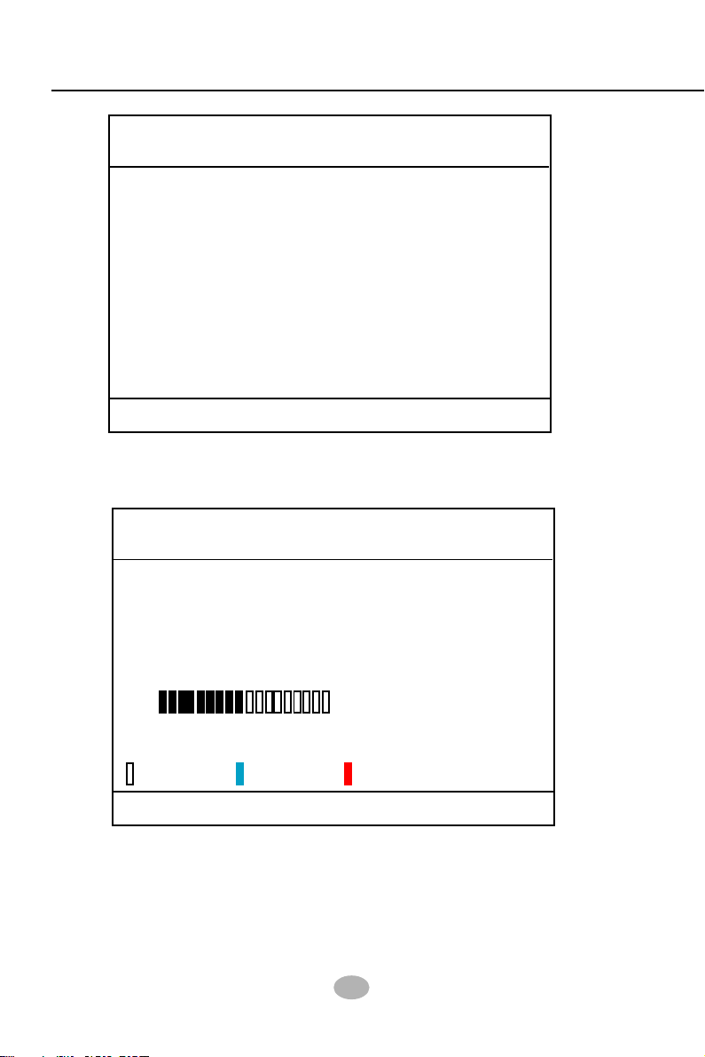
AwardBIOS Flash Utility V8.23F
(C)Phoenix Technologies Ltd. All Rights Reserved
Flash Type -
File Name to Program :
Message: Please input File Name !
Award Flash Memory Writer Start Screen
AwardBIOS Flash Utility V8.23F
(C)Phoenix Technologies Ltd. All Rights Reserved
Flash Type - PMC Pm49FL002T LPC/FWH
File Name to Program : 75FRN2.bin
Writing Flash Memory - 0FE00 OK
Write OK No Update Write Fail
Warning: Don’t Turn Off Power Or Reset System !
BIOS Image File is for nForce Chipset Only !
Award Flash Memory Writer Process Screen
52
Page 50

Chapter 4 BIOS Setup
4-6 BIOS SETUP --- CMOS Setup Utility
Warning and Tips: If changing CMOS Configuration causes difficulty in
rebooting system, you can take the following measures:
1. At pressing the power button to reboot, press the “Insert” key at the
same time. As soon as the screen displays the booting message,
release the “Insert” key and press “Delete” key to enter CMOS Setup
Utility . Then choose the “Load Optimized (Optimal) Defaults” menu
to restore the default values for a new start. Or,
2. Open your machine cabinet and clear CMOS with jumper setting.
Please refer to the Jumper Setting Section of this User manual.
4-6.1 CMOS Setup Utility
This mainboard comes with the AWARD BIOS from AWARD Software
Inc. Enter the CMOS Setup Utility Main Menu by:
1. Turn on or reboot your system. After a series of diagnostic checks,
the following message will appear:
PRESS <DEL> TO ENTER SETUP
2. Press <DEL> key and the main program screen will appear as follows.
Phoenix - AwardBIOS CMOS Setup Utility
Standard CMOS Features
Advanced BIOS Features
Advanced Chipset Features
Integrated Peripherals
Power Management Setup
PnP/PCI Configurations
SmartDoc Anti-Burn Shield
Esc: Quit : Select Item
F10: Save & Exit Setup
Time, Date, Hard Disk Type...
Frequency/Voltage Control
Load Optimized Defaults
Set Supervisor Password
Set User Passward
Save & Exit Setup
Exit Without Saving
3. Use the arrow keys on your keyboard to select an option, and press
<Enter>. Modify the system parameters to reflect the options installed
in your system.
4. You may return to the Main Menu anytime by pressing <ESC>.
5. In the Main Menu, “SAVE AND EXIT SETUP” saves your changes
and reboots the system, and “EXIT WITHOUT SAVING” ignores your
changes and exits the program.
53
Page 51

K8AV-R
4-6.2 Standard CMOS Setup
Standard CMOS Setup records some basic system hardware
configuration and sets the system clock and error handling. You only
need to modify the configuration values of this option if you want to
change your system hardware configuration or when the data stored in
the CMOS memory gets lost or damaged.
Run the Standard CMOS Setup as follows:
1. Choose “Standard CMOS Setup” from the Main Menu and a screen
with a list of options will appear:
Phoenix - AwardBIOS CMOS Setup Utility
Standard CMOS Features
Date (mm:dd:yy) Fri, Sep 5 2003
Time (hh:mm:ss) 9 : 41 : 11
IDE Channel 0 Master WDC WD400BB-00DEA0
IDE Channel 0 Slave None
IDE Channel 1 Master None
IDE Channel 1 Slave None
Drive A 1.44M, 3.5 in.
Drive B None
Video EGA/VGA
Halt On All, But Keyboard
Base Memory 640K
Extended Memory 252928K
Total Memory 253952K
:Move Enter: Select +/-/PU/PD: Value F10: Save ESC: Exit F1: General Help
F5: Previous Values F6: Fail-Safe Defaults F7: Optimized Defaults
Item Help
Menu Level
Change the day,
month, year and
century
2. Use one of the arrow keys to move between options and modify the
selected options by using PgUp / PgDn / + / - keys.
3. Press <ESC> to return to the Main Menu when you finish setting up
all items. The following item descriptions are provided as a quick
guide to your setup.
54
Page 52

Chapter 4 BIOS Setup
Date (mm:dd:yy) The BIOS determines the day of the week from the
other date information. This field is for information
only.
Press the left or right arrow key to move to the
desired field (date, month, year). Press the PgUp
or PgDn key to increment the setting, or type the
desired value into the field.
Time (hh:mm:ss) The time format is based on the 24-hour military-time
clock. For example, 1 p.m. is 13:00:00. Press the
left or right arrow key to move to desired field. Press
the PgUp or PgDn key to increment the setting, or
type the desired value into the field.
Channel 0 / Channel 1
Master / Slave
This field records the specifications for all non-SCSI
hard disk drives installed in your system. Refer to
the respective documentation on how to install the
drives.
Phoenix - AwardBIOS CMOS Setup Utility
IDE HDD Auto-Detection Press Enter
IDE Channel 0 Master Auto
Access Mode Auto
Capacity 40022MB
Cylinder 19158
Head 16
Precomp 0
Landing Zone 19157
Sector 255
:Move Enter: Select +/-/PU/PD: Value F10: Save ESC: Exit F1: General Help
F5: Previous Values F6: Fail-Safe Defaults F7: Optimized Defaults
IDE Primary Master
Item Help
Menu Level
To auto-detect the
HDD’s size, head...
on this channel
55
Page 53

K8AV-R
Drive A / Drive B Select this field to the type(s) of floppy disk drive(s)
installed in your system. The choices are:
360KB, 5.25 in.
1.2MB, 5.25 in.
720KB, 3.5 in.
1.44MB, 3.5 in.
2.88MB, 3.5 in.
None
Video Select the type of primary video subsystem in your
computer. The BIOS usually detects the correct video
type automatically. The BIOS supports a secondary
video subsystem, but you do not select it in setup.
Halt On During the power-on self-test (POST), the computer
stops if the BIOS detects a hardware error. You can
tell the BIOS to ignore certain errors during POST
and continue the boot-up process.
Base Memory Typically 640KB. Also called conventional memory.
The DOS operating system and conventional applications use this area.
Extended Memory Above the 1MB boundary. Early IBM personal
computers could not use memory above 1MB, but
current PCs and their software can use extended
memory.
Total Memory This option shows system memory capacity.
56
Page 54

Chapter 4 BIOS Setup
4-6.3 Advanced BIOS Features
Advanced BIOS Features improves your system performance or sets
up system features according to your preference.
Run the Advanced BIOS Features as follows:
1. Choose “Advanced BIOS Features” from the Main Menu and a screen
with a list of options will appear:
Phoenix - AwardBIOS CMOS Setup Utility
Advanced BIOS Features
Virus Warning Disabled
CPU Internal Cache Enabled
External Cache Enabled
CPU L2 Cache ECC Checking Enabled
Quick Power On Self Test Enabled
First Boot Device Floppy
Second Boot Device Hard Disk
Third Boot Device CDROM
Boot Other Device Enabled
Swap Floppy Drive Disabled
Boot Up Floppy Seek Disabled
Boot Up NumLock Status On
Typematic Rate Setting Disabled
x Typematic Rate (Chars/Sec) 6
x Typematic Delay (Msec) 250
Security Option Setup
OS Select For DRAM > 64MB Non-OS2
Video BIOS Shadow Enabled
: Move Enter: Select +/-/PU/PD: Value F10: Save Esc: Exit F1: General Help
F5: Previous Values F6: Fail-Safe Defaults F7: Optimized Defaults
Item Help
Menu Level
To choose the VIRUS
warning feature for
IDE Hard Disk boot
sector
protection. If this
functions is enabled
and someone attempt
to write data into this
area, BIOS will show a
warning message on
screen and alarm beep
57
Page 55

K8AV-R
2. Use one of the arrow keys to move between options and modify the
selected options by using PgUp / PgDn / + / - keys. An explanation
of the <F> keys follows:
<F1>: “Help” gives options available for each item.
<F5>: Get the previous values. These values are the values with which the
user starts the current session.
<F6>: Load all options with the BIOS default values.
<F7>: Load all options with the Setup default values.
3. Press <ESC> to return to the Main Menu when you finish setting up
all items. The following item descriptions are provided as a quick
guide to your setup.
Virus Warning Allows you to enable/disable the Virus Warning
function. If this function is enabled, some attempt to
write data into BIOS will bring up a warning message on the screen.
CPU Internal / External
Cache
Cache memory is additional memory that is much
faster than conventional DRAM (system memory).
CPUs from 486-type up contain internal cache
memory (L1), and most, but not all, modern PCs
have additional (external) cache memory (L2).
When the CPU requests data, the system transfers
the requested data from the main DRAM into cache
memory, for faster access by the CPU.
58
Page 56

Chapter 4 BIOS Setup
CPU L2 Cache ECC
Checking
Quick Power On Self
First/Second/Third/
Boot Other Device
Swap Floppy Drive When enabled, floppy drives A and B will be ex-
Boot Up Floppy Seek When enabled, the BIOS tests (seeks) floppy drives
To enable/disable CPU L2 Cache Error Correcting Code
Checking .
Select Enabled to reduce the amount of time required to
Test
run the power-on self-test (POST). A quick POST skips
certain steps. We recommend that you normally enable
quick POST.
The BIOS attempts to load the operating system from
the devices in the sequence selected in these items.
The choices: Floppy; LS120; ZIP100; HDD;
CDROM; USB-FDD; USB-ZIP; USB-CDROM; LAN;
Disabled
changing without any physical connection and modification on the cables.
to determine whether they have 40 or 80 tracks. Only
360-KB floppy drives have 40 tracks; drives with
270KB, 1.2MB, and 1.44MB capacity all have 80
tracks. Because very few modern PCs have 40-track
floppy drives, we recommend that you set this field
to disabled to save time.
Boot Up NumLock
Status
Typematic Rate Setting When Disabled, the following two items (Typematic
Toggle between On or Off to control the state of
the NumLock key when the system boots. If On,
the numeric keypad is in numeric mode. If off, the
numeric keypad is in cursor control mode.
Rate and Typematic Delay) are irrelevant. Keystroke
repeats at a rate determined by the keyboard controller in your system.
When Enabled, you can select a typematic rate and
typematic delay.
59
Page 57

K8AV-R
Typematic Rate (Chars
/ Sec)
Typematic Delay
(Msec)
Security Option If you have set a password, select whether the
OS Select For DRAM >
64MB
Video BIOS Shadow
When the typematic rate setting is enabled, you can
select a typematic rate (the rate at which character
repeats when you hold down a key) of 6, 8, 10, 12,
15, 20, 24, or 30 characters per second.
Choices: 250; 500; 750; 1000. This option sets the
time interval for displaying the first and the second
characters. If enabled, the time interval is optional.
password is required every time the System
boots, or only when you enter setup.
Choices: System; Setup(default)
Select OS2 only if you are running OS/2 operating
system with greater than 64MB of RAM on your
system.
To enable / disable Video BIOS Shadow function.
To enable the function will copy Video BIOS to
shadow RAM to improve performance.
60
Page 58
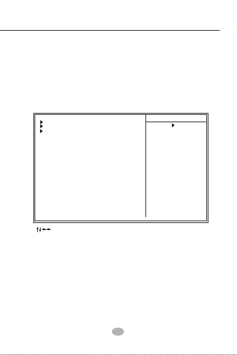
Chapter 4 BIOS Setup
4-6.4 Advanced Chipset Features
Advanced Chipset Features is used to modify the values of chipset
buffers. These buffers control the system options.
Run the Advanced Chipset Features as follows:
1. Choose “Advanced Chipset Features” from the Main Menu and a
list of option will appear:
Phoenix - AwardBIOS CMOS Setup Utility
Advanced Chipset Features
DRAM Configuration Press Enter
AGP & P2P Bridge Control Press Enter
LDT & PCI Bus Control Press Enter
Memory Hole Disabled
VLink DATA Rate 8X
Init Display First PCI Slot
System BIOS Cacheable Disabled
: Move Enter: Select +/-/PU/PD: Value F10: Save Esc: Exit F1: General Help
F5: Previous Values F6: Fail-Safe Defaults F7: Optimized Defaults
Item Help
Menu Level
DRAM timing and control
2. Use one of the arrow keys to move between options and modify the
selected options by using PgUp / PgDn / + / - keys. An explanation
of the <F> keys follows:
<F1>: “Help” gives options available for each item.
<F5>: Get the previous values. These values are the values with which the
user starts the current session.
<F6>: Load all options with the BIOS default values.
<F7>: Load all options with the Setup default values.
3. Press <ESC> to return to the Main Menu when you finish setting up
all items. The following item descriptions are provided as a quick
guide to your setup.
61
Page 59

K8AV-R
DRAM Configuration:
To press< Enter > on DRAM Configuration will reveal the following item
(s).
DDR Timing Setting by
Current FSB
Frequency
Current DRAM
Frequency
BIOS shows the actual Front Side Bus frequency.
BIOS shows the actual DRAM frequency.
To manually/ automatically set the DDR Timing.
Max Memclock (Mhz)
To manually set the memory clock if you have set
“by manual” in above option.
Choice: 100; 133; 166; 200
AGP & P2P Bridge Control:
To press< Enter > on AGP & P2P Bridge will reveal the following item
(s).
AGP Aperture Size Series of options are available: 32, 64, 128, 256M.
Memory mapped and graphics data structures can
reside in a Graphics Aperture. This area is like a
linear buffer. BIOS will automatically report the starting address of this buffer to the O.S. The default
setting is 64MB.
AGP Driving Control
AGP Driving Value
AGP Fast Write This item will enable the AGP mode into fast write
DBI Output for AGP
Trans.
AGP Master 1 WS
To automatically/manually set AGP Driving Control.
To input AGP Driving Value if you have set “by
manual” in above option.
mode. If your graphics card does not support this
function, please do not enable this function.
To enable / disable the DBI Output for Transfer
function.
To enable / disable (default) the support of AGP
Write
Master 1 Waite State Write.
AGP Master 1 WS
Read
To enable / disable (default) the support of AGP
Master 1 Waite State Read.
62
Page 60

Chapter 4 BIOS Setup
LDT & PCI Bus Control:
To press< Enter > on LDT & PCI Bus Control will reveal the following
item(s).
Upstream LDT Bus
Width
To set Upstream LDT BUS Width.
Choices: 8 bit; 16 bit
Downstream LDT Bus
Width
LDT Bus Frequency
PCI1 Master 0 WS
PCI2 Master 0 WS
PCI1 Post Write To enable / disable (default) the support of PCI1 Post
PCI2 Post Write To enable / disable (default) the support of PCI2 Post
Memory Hole To enabled / disabled (default) the support of
VLink Data Rate To set VLink Data Rate.
To set Downstream LDT BUS Width.
Choices: 8 bit; 16 bit
To set LDT Bus Frequency.
Choices: Auto; 200MHz; 400MHz; 600MHz; 800MHz
To enable / disable the support of PCI1 Master 0
Write
Wait State Write.
To enable / disable (default) the support of PCI2
Write
Master 0 Wait State Write.
Write.
Write.
Memory Hole which is reserved for ISA card.
Choices: Disabled; 15MB-16MB
Choices: 8X; 4X
Init Display First Initialize the AGP video display before initializing any
other display device on the system. Thus the AGP
display becomes the primary display.
System BIOS
Cacheable
Selecting Enabled allows caching of the system
BIOS ROM at F0000h-FFFFFh, resulting in better
system performance.
63
Page 61
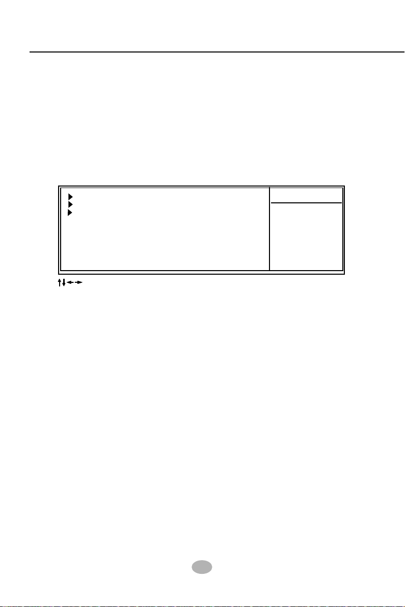
K8AV-R
4-6.5 Integrated Peripherals
Integrated Peripherals option allows you to get some information inside
your system when it is working.
Run the Integrated Peripherals as follows:
1. Choose “Integrated peripherals” from the Main Menu and a list of
options will appear:
Phoenix - AwardBIOS CMOS Setup Utility
Integrated Peripherals
VIA onChip IDE Device Press Enter
VIA onChip PCI Device Press Enter
Super IO Device Press Enter
: Move Enter: Select +/-/PU/PD: Value F10: Save Esc: Exit F1: General Help
F5: Previous Values F6: Fail-Safe Defaults F7: Optimized Defaults
Item Help
2. Use one of the arrow keys to move between options and modify the
selected options by using PgUp / PgDn / + / - keys. An explanation
of the <F> keys follows:
<F1>: “Help” gives options available for each item.
<F5>: Get the previous values. These values are the values with which the
user starts the current session.
<F6>: Load all options with the BIOS default values.
<F7>: Load all options with the Setup default values.
3. Press <ESC> to return to the Main Menu when you finish setting up
all items. The following item descriptions are provided as a quick
guide to your setup.
64
Page 62

Chapter 4 BIOS Setup
VIA OnChip IDE Device:
To press< Enter > on VIA OnChip IDE Device will reveal the following
item(s).
Promise RAID Mode To enable/disable the Promise RAID on board.
On-Chip IDE Channel
IDE Prefetch Mode The on-board IDE drive supports IDE prefetching
Primary
Master / Slave PIO
Secondary
Master / Slave PIO
Primary
Master / Slave UDMA
Secondary
Master / Slave UDMA
The chipset contains a PCI IDE interface with
10/11
support from two IDE channels. Select Enabled
to activate the first and/or the second IDE
interface. Select Disabled to inactivate an interface if you install a primary and/or second addon IDE interface.
Choices: Enabled; Disabled
for faster drive accesses. If the IDE device doesn’t
support prefetching, set this field to Disabled.
The choices: Enabled; Disabled
Choose Auto or Mode 0~4. The BIOS will detect the
HDD mode type automatically when you choose
Auto. You need to set to a lower mode than Auto
when your hard disk becomes unstable.
Choices: Auto(default); Mode 0; Mode 1; Mode
2; Mode 3; Mode 4
Ultra DMA33/66/100/133 implementation is possible
only if your IDE hard drive supports it, if the operating environment includes a DMA drive, and if your
system software supports Ultra DMA33/66/100/133.
Select “Auto” to enable BIOS support.
Choices: Auto(default); Disabled
IDE HDD Block Mode Block mode is also called block transfer, multiple
commands, or multiple sector read/write. If your IDE
hard drive supports block mode (most new drives
do), select Enabled for automatic detection of the
optimal number of block read/write per sector the
drive can support.
65
Page 63

K8AV-R
VIA OnChip PCI Device:
To press< Enter > on VIA OnChip IDE Device will reveal the following
item(s).
VIA-3058 AC97 Audio Select “Auto” to use the on-chip audio of your
system. If user wants to use add-on sound card,
this item must be disabled.
OnChip USB
Controller
OnChip EHCI
Controller
USB Keyboard
Support
USB Mouse
Support
To enable/disable the onchip USB controller.
Choices: All Enabled; All Disabled
To enable/disable the onchip EHCI controller.
Select Enabled if your system contains a Universal
Serial Bus (USB) controller and you have a USB
keyboard.
Select Enabled if your system contains a Universal
Serial Bus (USB) controller and you have a USB
mouse.
SuperIO Device:
To press< Enter > on SuperIO Device will reveal the following item(s).
Onboard FDC
Controller
Onboard Serial
Port 1 / Port 2
Select Enabled if your system has a floppy drive
controller (FDC) installing in the system board and
you want to use it. If you install add-in FDC or the
system has no floppy drive, select Disabled in this
field.
Select a logical COM port name and matching
address for the first and second serial ports.
Select an address and corresponding interrupt
for the first and second serial ports.
Choices: Disabled; Auto;
3F8/IRQ4; 2F8/IRQ3;
3E8/IRQ4; 2E8/IRQ3
66
Page 64

Chapter 4 BIOS Setup
UART Mode Select The serial port on your system may offer a vari-
ety of infrared port modes. Click here for a description of various modes.
The choices: Normal(default); IrDA; ASKIR; SCR
X UR2 Duplex Mode This options controls the operating mode between
receiving and transmitting of IrDA or ASKIR or SCR.
The operating mode will be synchronous bi-directional transmission and reception when Full mode
is selected. Nevertheless, the operating mode will
be asynchronous bi-directional transmission and reception when Half mode is selected.
Choices: Half; Full
Onboard Parallel Port This item allows you to determine onboard parallel
port controller I/O address setting.
Choices: 378H/IRQ7; 278H/IRQ5; 3BC/
IRQ7; Disabled
Parallel Port Mode Select an operating mode for the on-board parallel
(printer) port.
Choices: SPP; EPP; ECP; ECP+EPP
X ECP mode Use DMA Select a DMA channel for the port when you choose
ECP or ECP+EPP mode for the Parallel Port Mode.
Choices: 1; 3
Game Port Address This item allows you to select the Game Port
Address.
Choices: Disabled, 201, 209
Midi Port Address To configure the onboard Midi port address.
Choices: Disabled, 330, 300
Midi Port IRQ This item allows you to select the Midi Port IRQ.
Choices: 5, 10(default)
67
Page 65

K8AV-R
4-6.6 Power Management Setup
Power Management Setup allows you to set the system’s power saving
functions.
Run the Power Management Setup as follows:
1. Choose “Power Management Setup” from the Main Menu and a list
of options will appear:
Phoenix - AwardBIOS CMOS Setup Utility
Power Management Setup
ACPI function Enabled
ACPI Suspend Type S1(POS)
Power Management Option User Define
HDD Power Down Disabled
Suspend Mode Disabled
Video Off Option Suspend -> Off
Video Off Method V/H SYNC+Blank
MODEM Use IRQ 3
Soft-off by PBTN Instant-off
Run VGABIOS if S3 Resume Auto
AC Loss Auto Restart Off
IRQ/Event Activity Detect Press Enter
PS2 KB Wakeup Select Hot Key
PS2KB Wakeup from S3/S4/S5 Disabled
x Power Button Lock Disabled
PS2MS Wakeup from S3/S4/S5 Disabled
USB Resume from S3 (Optional) Disabled
VGA Off
LPT & COM LPT/COM
HDD & FDD On
PCI Master Off
PowerOn by PCI Card Disabled
Modem Ring Resume Disabled
x Date (of Month) 0
x Resume Time (hh: mm: ss ) 0 : 0 : 0
IRQs Activity Monitoring Press Enter
Item Help
: Move Enter: Select +/-/PU/PD: Value F10: Save Esc: Exit F1: General Help
F5: Previous Values F6: Fail-Safe Defaults F7: Optimized Defaults
2. Use one of the arrow keys to move between options and modify the
selected options by using PgUp / PgDn / + / - keys. An explanation
of the <F> keys follows:
<F1>: “Help” gives options available for each item.
<F5>: Get the previous values. These values are the values with which the
user starts the current session.
<F6>: Load all options with the BIOS default values.
<F7>: Load all options with the Setup default values.
3. Press <ESC> to return to the Main Menu when you finish setting up
all items. The following item descriptions are provided as a quick
guide to your setup.
68
Page 66

Chapter 4 BIOS Setup
ACPI Function Select Enabled(default) only if your computer’s op-
erating system supports the Advanced Configuration and Power Interface (ACPI) specification.
Currently, Windows 98SE/ME, Windows 2000 and
Windows XP supports ACPI.
ACPI Suspend Type This item allows you to select the ACPI Suspend
type. You can select S3(STR) for Suspending To
RAM if your system supports this mode. Or you can
select S1(POS) for Power On Suspend under ACPI
mode.
Choices: S1(POS)(default);S3(STR); S1&S3
Power Management
Option
This option allows you to select the type (or degree)
of power saving for Doze, Standby, and Suspend
modes.
This table describes each power management
mode:
Max Saving
User Define
Min Saving
Maximum power savings. Inactivity period is 1 minute in each mode.
Set each mode in dividually. Select time-out period in the section for each
mode stated below.
Minimum power savings. Inactivity period is 1 hour in each mode (except the
hard drive).
HDD Power Down When enabled after the set time of system inactivity,
the hard disk drive will be powered down while all
other devices remain active.
Suspend Mode When enabled after the set time of system inactivity,
the whole system will be suspended.
Video Off Option
To set Video Off mode of the system.
Choices: Always On; Suspend -> Off
69
Page 67

K8AV-R
Video Off Method
This determines the manner by which the monitor is
blanked.
V/H
SYNC+Blank
Blank Screen
DPMS Support
MODEM Use IRQ
This selection will cause the system to turn off the vertical and horizontal
snchronization ports and write blanks to the video buffer.
This option only writes blanks to the video buffer.
Select this option if your monitor supports the Display Power Management
Singaling (DPMS) standard of the Video Electronics Standards to select video
power management values.
To set IRQ Modem should use. If users do not have
a modem, please set NA.
Soft-Off by PWRBTN To turn off the system instantly or after 4 seconds
by power button.
Run VGABIOS if S3
Resume
To enable/disable to run VGABIOS if S3 Resume.
Choices: Auto; Yes; No
AC Loss Auto restart To enable/disable to run VGABIOS if S3 Resume.
Choices: Auto; Yes; No
70
Page 68

Chapter 4 BIOS Setup
IRQ/Event Activity Detect:
To press< Enter > on IRQ/Event Activity Detect will reveal the following
item(s).
PS2KB Wakeup Select If keyboard power on function is set at “Password”,
this item shows up to allow you to type a password
for the power-on function.
Choices: Hot key; Password
PS2KB Wakeup from
S3/S4/S5
PS2MS Wakeup from
S3/S4/S5
(Optional) USB Re-
sume from S3
VGA To enable/disable VGA Wakeup function.
LPT & COM To enable/disable LPT & COM Wakeup function.
HDD & FDD To enable/disable HDD & FDD Wakeup function.
PCI Master To enable/disable PCI Master Wakeup function.
Wake Up On PME
Modem Ring Resume
RTC Alarm Resume
To set the hot key to boot up the system.
To enable/disable PS/2 Mouse Wakeup function.
This item allows you to enable / disable the USB
device Wakeup function from S3 mode.
To enable / disable(default) the Wake on PME
function.
To enable / disable(default) the wake on ring signal
function.
An input signal on the serial Ring Indicator (RI) Line
(in other words, an incoming call on the modem)
awakens the system from a soft off state.
To enable / disable the RTC Alarm Resume
function.
Date (of Month)
Resume Time (Hour /
Minute / Second)
If RTC Alarm Resume is enabled, this field allows
you to set the Alarm Date, Hour, Minute and
Second.
Date Choices: 01 ~ 31
Hour Choices: 00 ~ 23
Minute Choices: 00 ~ 59
Second Choices: 00 ~ 59
71
Page 69

K8AV-R
IRQs Activity Monitoring:
To press< Enter > on IRQs Activity Monitoring will reveal the following
item(s).
IRQ3,4,5,7,9,10,11,12,
13,14,15
To enable/disable IRQ Assignment.
72
Page 70

Chapter 4 BIOS Setup
4-6.7 PnP / PCI Configuration
PnP/PCI Configuration allows you to modify the system’s power saving
functions.
Run the PnP/PCI Configuration as follows:
1. Choose “PnP/PCI Configuration” from the Main Menu and a screen
with a list of options will appear:
Phoenix - AwardBIOS CMOS Setup Utility
PnP PCI Configurations
PNP OS Installed No
Reset Configuration Data Disabled
Resources Controlled by Auto(ESCD)
x IRQ Resources Press Enter
PCI/VGA Palette Snoop Disabled
Assign IRQ For VGA Enabled
Assign IRQ For USB Enabled
: Move Enter: Select +/-/PU/PD: Value F10: Save Esc: Exit F1: General Help
F5: Previous Values F6: Fail-Safe Defaults F7: Optimized Defaults
Item Help
2. Use one of the arrow keys to move between options and modify the
selected options by using PgUp / PgDn / + / - keys. An explanation
of the <F> keys follows:
<F1>: “Help” gives options available for each item.
<F5>: Get the previous values. These values are the values with which the
user starts the current session.
<F6>: Load all options with the BIOS default values.
<F7>: Load all options with the Setup default values.
3. Press <ESC> to return to the Main Menu when you finish setting up
all items. The following item descriptions are provided as a quick
guide to your setup.
73
Page 71

K8AV-R
PNP OS Installed Allows you to configure the PNP devices by BIOS
or O/S.
Choices: No(by BIOS); Yes(by O/S)
Reset Configuration
Normally, you leave this Disabled(default). Select
Data
Enabled to reset Extended System Configuration
Data (ESCD), when you exit Setup if you have installed a new add-on and the system reconfiguration
has caused such a serious conflict that the operating system cannot boot.
Resource ControlledByThe Plug and Play Award BIOS can automatically
configure all the boot and Plug and Play compatible
devices. If you select Auto, all the interrupt request
(IRQ) and DMA assignment fields will not appear,
as the BIOS automatically assigns them. If you select Manual, the IRQ Resources item will appear for
your configuration (see below).
IRQ Resources Press Enter. Please refer to the list below:
Phoenix - AwardBIOS CMOS Setup Utility
IRQ Resources
IRQ-3 assigned to PCI Device
IRQ-4 assigned to PCI Device
IRQ-5 assigned to PCI Device
IRQ-7 assigned to PCI Device
IRQ-9 assigned to PCI Device
IRQ-10 assigned to PCI Device
IRQ-11 assigned to PCI Device
IRQ-12 assigned to PCI Device
IRQ-14 assigned to PCI Device
IRQ-15 assigned to PCI Device
: Move Enter: Select +/-/PU/PD: Value F10: Save Esc: Exit F1: General Help
F5: Previous Values F6: Fail-Safe Defaults F7: Optimized Defaults
Item Help
PCI/VGA Palette Snoop This option allows the BIOS to preview VGA status,
and to modify the information delivered from the
feature Connector of the VGA card to MPEG card.
This option can solve the display inversion to black
after you have used a MPEG card.
Assign IRQ For VGA To enable/disable to assign IRQ for VGA.
Assign IRQ For USB To enable/disable to assign IRQ for USB.
74
Page 72

Chapter 4 BIOS Setup
4-6.8 SmartDoc Anti-Burn Shield
This section helps you to get more information about your system including CPU temperature, FAN speed and voltage. It is recommended
that you contact your mainboard supplier to get proper values about
the setting of the CPU temperature.
Run the “SmartDoc Anti-Burn Shield” as follows:
1. Choose “SmartDoc Anti-Burn Shield” from the Main Menu and a
screen with a list of options will appear:
Phoenix - AwardBIOS CMOS Setup Utility
SmartDoc Anti-Burn Shield
Item Help
Vcore 1.56V
VDD 2.51V
3.3V 3.26 V
+5V 5.02V
+12V 11.75V
-12V -11.74V
+1.5V 1.53V
+5Vsb 5.05V
Voltage Battery 3.24V
CPU Internal Temp. 60˚C
System Temp. 33˚C
CPU FAN Speed 5232 RPM
System FAN Speed 0 RPM
: Move Enter: Select +/-/PU/PD: Value F10: Save Esc: Exit F1: General Help
F5: Previous Values F6: Fail-Safe Defaults F7: Optimized Defaults
2. Use one of the arrow keys to move between options and modify the
selected options by using PgUp / PgDn / + / - keys.
<F1>: “Help” gives options available for each item.
<F5>: Get the previous values. These values are the values with which the
user starts the current session.
<F6>: Load all options with the BIOS default values.
<F7>: Load all options with the Setup default values.
3. Press <ESC> to return to the Main Menu when you finish setting up
all items. The following item descriptions are provided as a quick
guide to your setup.
75
Page 73

K8AV-R
Vcore Shows CPU core actual voltage value.
VDD Shows North Bridge actual voltage value.
3.3V, +5V, +12V, -12V,
+1.5V, 5VSB
Voltage Battery Shows voltage value of the battery on board.
CPU Internal Temp. Shows current CPU internal temperature.
System Temp. Shows current system temperature.
CPU FAN Speed These fields display the current speed of the CPU
System FAN Speed These fields display the current speed of the Sys-
Shows actual voltage value of all these default voltage value on board.
fan.
tem fan.
76
Page 74
Chapter 4 BIOS Setup
4-6.9 Frequency/Voltage Control
Run the “Frequency/Voltage Control” as following:
1. Choose “Frequency/Voltage Control” from the Main Menu and a
screen with a list of options will appear:
Phoenix - AwardBIOS CMOS Setup Utility
Frequency/Voltage Control
Item Help
Auto Detect PCI Clk Enabled
Spread Spectrum Disabled
CPU Clock 200MHz
CPU Vcore Select Default
AGP Voltage Select 1.5V
DIMM Voltage Select 2.6V
2.5V Select 2.5V
: Move Enter: Select +/-/PU/PD: Value F10: Save Esc: Exit F1: General Help
F5: Previous Values F6: Fail-Safe Defaults F7: Optimized Defaults
2. Use one of the arrow keys to move between options and modify the
selected options by using PgUp / PgDn / + / - keys.
<F1>: “Help” gives options available for each item.
<F5>: Get the previous values. These values are the values with which the
user starts the current session.
<F6>: Load all options with the BIOS default values.
<F7>: Load all options with the Setup default values.
3. Press <ESC> to return to the Main Menu when you finish setting up
all items. The following item descriptions are provided as a quick
guide to your setup.
77
Page 75

K8AV-R
PCI Clock Auto
Detection
Spread
Spectrum
CPU Clock This item allows you to set CPU Clock.
CPU Vcore
Select
AGP Voltage
Select
DIMM Voltage
Select
2.5V Voltage
Select
To enable / disablethis auto detection function on
PCI clock.
This function will reduce the EMI (Electromagnetic
Interference) in your system. If you do not have an
EMI problem, leave this item disabled.
Choices: 200MHz ~250MHz in 1MHz stepping.
To configure the CPU Voltage. Usually, to raise CPU
voltage will raise the chance of CPU overclocking
and yet risk damage of CPU.
Choices: Default; 0.800V ~1.700V in 0.05V stepping
To configure the AGP Voltage.
Choices: 1.5V; 1.6V; 1.7V; 1.8V
To configure the DIMM Voltage.
Choices: 2.6V; 2.7V; 2.8V; 2.9V
To configure the VDD Voltage.
Choices: 2.5V; 2.6V; 2.7V; 2.8V
78
Page 76

Chapter 4 BIOS Setup
4-6.10 Load Optimized Defaults
When you press <Enter> on this item, you will get a confirmation dialog
box with a message similar to:
“ Load Optimized Defaults (Y / N) ? N ”
Phoenix - AwardBIOS CMOS Setup Utility
Standard CMOS Features
Advanced BIOS Features
Advanced Chipset Features
Integrated Peripherals
Power management Setup
PnP/PCI Configurations
SmartDoc Anti-Burn Shield
Esc: Quit : Select Item
F10: Save & Exit Setup
Load Optimized Defaults [Y/N] Y
Change CPU Clock & Voltage
Frequence/Voltage Control
Load Optimized Defaults
Set Supervisor Password
Set User Passward
Save & Exit Setup
Exit Without Saving
“Y” is for “Yes”, and “N” is for “No”.
Pressing “Y” loads the BIOS Optimized default values to restore the
BIOS to its original status.
79
Page 77

K8AV-R
4-6.11 SET SUPERVISOR / USER PASSWORD
These two options allow you to set your system passwords. Normally,
the supervisor has a higher priority to change the CMOS setup option
than the users. The way to set up the passwords for both Supervisor
and Users are as follows:
1. Choose “Change Password” in the Main Menu and press <Enter>.
Then following message appears:
“Enter Password : “
2. The first time you run this option, enter your password up to 8 characters and press <Enter>. (The screen does not display the entered
characters.)
3. After you enter the password, the following message appears prompting you to confirm the password:
“Confirm Password : “
4. Enter the same password “exactly” the same as you have just typed
to confirm the password and press <Enter>.
5. Move the cursor to Save & Exit Setup to save the password.
6. If you need to delete the password entered before, choose the Supervisor Password and press <Enter>. It will delete the password
that you have entered before.
7. Move the cursor to Save & Exit Setup to save the option you have
just configured; otherwise the old password will still be there the next
time you turn your system on.
8. Press <Enter> to exit to the Main Menu.
RxD , TxD Active The option controls the speed between receiving and
transmitting of IrDA or ASKIR when using.
Choices: Hi,Hi; Hi,Lo; Lo,Hi; Lo,Lo
IR Transmission Delay When UART Mode is selected in IrDA or ASKIR
mode, it allows you to enable / disable IR Transmission Delay.
EPP Mode Select Select EPP Mode when you choose EPP or
ECP+EPP mode in the Parallel Port Mode.
Choices: EPP1.7; EPP1.9
80
Page 78

Chapter 4 BIOS Setup
4-6.12 SAVE & EXIT SETUP
SAVE & EXIT SETUP allows you to save all modifications you have
specified into the CMOS memory. Highlight this option on the Main Menu
and the following message appears:
“SAVE to CMOS and EXIT (Y/N) ? Y “
“Y” is for “Yes”, and “N” is for “No”.
Press <Enter> key to save the configuration changes.
4-6.13 EXIT WITHOUT SAVING
EXIT WITHOUT SAVING option allows you to exit the Setup Utility
without saving the modifications that you have specified. Highlight this
option on the Main Menu and the following message appears:
“Quit Without Saving (Y/N) ? N “
“Y” is for “Yes”, and “N” is for “No”.
You may change the prompt to “Y” and press <Enter> key to leave this
option .
81
Page 79

K8AV-R
Chapter 5 RAID & RAID Driver
Promise RAID Controller PDC20378 / 20376
Promise RAID (Redundant Array of Independent Disks) Controller PDC
20378 is to provide RAID configuration of RAID 0, RAID 1, and RAID
0+1 modes, while PDC20376 is to RAID configuration of RAID 1 and
RAID 2 only. RAID Drivers are enclosed in a Driver CD as well as a
Floppy diskette to support various RAID systems (Windows 98SE/Me/
2000/XP) setup.
This Chapter is to introduce the SATA RAID / SATA +
PATA RAID Configurations with PDC20378 :
5-0 About Disk Array................................................................... 85
5-0-1 Disk Array Interpretation..........................................................85
5-0-2 Disk Array Member .................................................................... 85
5-0-3 Disk Array Types Supported by PDC20378/PDC20376 .......85
5-1. SATARAID and PATA RAID Layout on K8AV-R .......... 86
5-2. First Step to Set up RAID - Populate Disk Drives.......... 86
5-3. To Enter RAID BIOS ........................................................... 86
5-4. To Enter the Main Menu of FastBuild Utility ................. 87
5-5. View Drive Assignment before RAID Setup .................... 88
5-6. Enter “Auto Setup” for RAID Setup ............................... 88
5-7. Choose “ Security” for RAID 0+1 (Stripe/Mirror) ........ 89
5-8. Press <Ctrl-Y> to Save the Choice .................................... 89
5-9. Create RAID only / Create and Quick Initialize............. 90
5-10. Array Created and Reboot System.................................. 90
5-11. Mirror/Stripe Array Detected at Reboot System .......... 91
5-12 To Install Promise RAID Driver ....................................... 92
5-12-1 To Install RAID Driver on Windows 2000/XP .....................92
5-12-2 To Install RAID Driver on Windows 98SE/Me .................... 95
82
Page 80

Chapter 5 RAID & RAID Driver
5-0 About Disk Array
5-0-1 Disk Array Interpretation
A “Disk Array” is formed from a group of 2 or more disk drives with the
RAID (Redundent Array of Independent Disks) technology. The aim of
a Disk Array is to provide better perfornance and/or data fault tolerance.
5-0-2 Disk Array Member
The individual disk drive in an array is called a “member”. Each member
of a specific disk array is coded in their “reserved sector” with
configuration information that identifies the drive as a member. All disk
members in a formed disk array are recognized as a single physical
drive to the system.
5-0-3 Disk Array Types Supported by PDC20378/PDC20376
1. RAID 0 (or Striping mode): supported by both PDC20378 and
PDC20376
RAID 0 is a group of 2 to 4 Disk Drives configured together with
RAID technology to provide better data transfer performance than a
single drive since the workload is balanced between the array
members. Reads and Writes of RAID 0 data are interleaved between
multiple drives. When any disk member fails, it affects the entire array.
The disk array size is equal to the number of drive members times
the smallest member capacity. For example, one 1GB and three 1.
2GB drives will form a 4GB (4x1GB) disk array.
2. RAID 1 (or Mirroring mode): supported by both PDC20378 and
PDC20376
RAID 1 is a group of 2 Disk Drives configured together with RAID
Technology to provide the fault tolerance function. Writes duplicate
data on to RAID 1 while reads are performed in parallel. If one of the
mirrored drives suffers a mechanical failure (e.g. spindle failure) or
does not respond , the remaining drive will continue to function. This
is called Fault Tolerance.
The drive capacity of RAID 1 is half the total drive capacity of two
equal-size drive.
3. RAID 0+1 (Mirror/Stripe): supported by PDC20378 only
RAID 0+1 is formed by a RAID 0 member mirrored to another RAID
member to establish a RAID 0+1 Array. RAID 0+1 requires at least 4
disk drive to set up the RAID 0+1 configuration.
83
Page 81

K8AV-R
5-1. SATARAID and PATA RAID Layout on K8AV-R
JKB1
Fan1
Mouse
1
(on top)
(underside)
PS/2 K/B
USB0
(on top)
(underside)
USB1
COM1
LPT1
COM2
Line
Out
Line
In
MIC
Game/MIDI Port
CD-In1
JAUD1
1
1
ALC650
AC'97
Codec
LPC I/O
IT8705
BIOS
Audio1
1
DDR 400/333/266 MHz
DIMM2
DIMM1
Fan2
Socket 754
VIA
K8T800
+12V Power
JCLK1
AGP 4X/8X
PCI 1
PCI 2
PCI 3
PCI 4
PCI 5
SCR1
1
WOL1
VT8235
USB2
1
1
1
Main Power
1
1
1
IDE1
FD1
IDE2
RT1
Li
Battery
VIA
1
JBAT1
CD
ATA2
1
IDE3
20
PDC20378
PWR
IR
NJ1
ATA1
-
USB3
LED
Fan3
+
HDD
1
1 IDE RAID connector (IDE3)
supporting 2 PATA RAID Hard
Disks (supported by PDC20378)
2 SATA connectors ATA1/ATA2
-
PWLED
+
RST
supporting 2 SATARAID Hard
SPK
Disks
K8AV-R
Chipset Promise PDC20378
supporting SATA/PATA RAID
Interfaces
5-2. First Step to Set up RAID - Populate Disk Drives
1. Connect 1 SATA Disk Drive to ATA1 and 1 SATA Disk Drive to ATA2.
2. Connect 1 PATA Disk Drives to IDE3.
3. 3 Disk drives can be set up into RAID 0 or 1 Array.
5-3. To Enter RAID BIOS
At booting system, the following screen will appear after “POST”.
FastTrak 378 (tm) BIOS Version 1.00.1.34
(c) 2002-2005 Promise Technology. Inc. All rights reserved.
No Array is defined...................
Press <Ctrl-F> to enter FastBuild (tm) Utility or
Press <ESC> to continue booting...
Following the instruction on the screen, press <Ctrl-F> to enter the
FastBuild (tm) Utility.
84
Page 82

Chapter 5 RAID & RAID Driver
5-4. To Enter the Main Menu of FastBuild Utility
The Main Menu will pop out as below:
FastBuild (tm) Utility 2.01 (c) 2002-2005 Promise Technology, Inc.
[ Main Menu ]
Auto Setup..............................[1]
View Drive Assignemnts..........[2]
Define Array............................[3]
Delete Array............................[4]
Rebuild Array..........................[5]
[ Keys Available ]
Press 1~5 to Select Option [Esc] Exit
1. Auto Setup.........[1]
Press figure “1” on keyboard to enter Auto Setup of RAID.”Auto Setup”
is available only if there are free disk drive detected in system.
2. View Drive Assignment.........[2]
Press figure “2” on keyboard to view the drive assignment detected
in system.
3. Define Array.........[3]
Press figure “3” on keyboard to view the defined Array already set up
in system.
4. Delete Array.........[4]
Press figure “4” on keyboard to enter the “Delete Array” field for
deleting Array already set up in system.
5. Rebuild Array.........[5]
Press figure “5” on keyboard to enter the “Rebuild Array” field for
rebuilding a defective array or RAID member. “Rebuild Array” is
available for “RAID 1 (Mirror)” or “RAIA 0+1 (Mirror/Stripe)” mode.
85
Page 83

K8AV-R
5-5. View Drive Assignment before RAID Setup
Press “2” to enter “View Drive Assignment” so that you can see the
status of all disk drives detected by RAID BIOS.
FastBuild (tm) Utility 2.01 (c) 2002-2005 Promise Technology, Inc.
[ View Drivers Assignments ]
Channel:ID Drive Model Capacity (MB) Assignment Mode
1: Mas ST380023AS 80026 Free U5
2: Mas ST380023AS 80026 Free U5
3: Mas QUANTUM FIREBALLP AS3 30020 Free U2
3: Mas ST330620A 30020 Free U2
[ Keys Available ]
[Esc] Exit MODE (D = DMA, U = UDMA)
Two drives are detected in one channel 3
as free drives (available for RAID setup)
Two drives are detected in channel 1 and 2
as free drives (available for RAID setup)
Totally 4 drives are
detected by RAID BIOS
5-6. Enter “Auto Setup” for RAID Setup
Press “1” to enter “Auto Setup” so that you can see the RAID choices.
FastBuild (tm) Utility 2.01 (c) 2002-2005 Promise Technology, Inc.
[ Auto Setup Options Menu ]
Optimize Array for: Performance
[ Array Setup Configuration ]
Mode ................................................Stripe
Spare Drive .......................................0
Drive(s) Used in Array..........................4
Array Disk Capacity (size in MB)..........120080
[ Keys Available ]
[ ,,Space] Change Option [ESC] Exit [Ctrl-Y] Save
86
Press “ <--- “ key to
change RAID option.
Page 84

Chapter 5 RAID & RAID Driver
5-7. Choose “ Security” for RAID 0+1 (Stripe/Mirror)
Press “1” to enter “Auto Setup” so that you can see the RAID choices.
FastBuild (tm) Utility 2.01 (c) 2002-2005 Promise Technology, Inc.
[ Auto Setup Options Menu ]
Security (0+1) mode is
Optimize Array for: Security
Security (0+1) mode is
selected.
selected.
[ Array Setup Configuration ]
Mode ................................................Mirror/Stripe
Spare Drive .......................................0
Drive(s) Used in Array..........................4
Array Disk Capacity (size in MB)..........60000
[ Keys Available ]
[ ,,Space] Change Option [ESC] Exit [Ctrl-Y] Save
5-8. Press <Ctrl-Y> to Save the Choice
When a RAID mode is chosen, press < Ctrl-Y> to save the choice.
Then select Y for “Create and Quick Initialize; or select N for “Create
only”.
FastBuild (tm) Utility 2.01 (c) 2002-2005 Promise Technology, Inc.
[ Auto Setup Options Menu ]
Optimize Array for: Security
[ Array Setup Configuration ]
Mode ................................................Mirror/Stripe
Spare Drive .......................................0
Drive(s) Used in Array..........................4
Array Disk Capacity (size in MB)..........60000
Do you want to do quick initialize or
create only? (Yes/No)
Y - Create and Quick Initialize
N - Create Only
[ Keys Available ]
[ ,,Space] Change Option [ESC] Exit [Ctrl-Y] Save
Press <Ctrl-Y> to save choice.
87
Page 85

K8AV-R
5-9. Create RAID only / Create and Quick Initialize
“Create Only” is for creating RAID without changing the disk data.
“Create and Quick Initialize” will create the RAID with clearing disk data.
FastBuild (tm) Utility 2.01 (c) 2002-2005 Promise Technology, Inc.
[ Auto Setup Options Menu ]
Optimize Array for: Security
[ Array Setup Configuration ]
Mode ................................................Mirror/Stripe
Spare Drive .......................................0
Drive(s) Used in Array..........................4
Array Disk Capacity (size in MB)..........60000
Choose Quick Initialize will delete
any existing data on your hard
disks.
Y - Continue, Others - Cancel
[ Keys Available ]
[ ,,Space] Change Option [ESC] Exit [Ctrl-Y] Save
5-10. Array Created and Reboot System
After choosing “Create Only” or Create and Quick Initialize”, next screen
will prompt you to reboot system.
Press any key to reboot.
FastBuild (tm) Utility 2.01 (c) 2002-2005 Promise Technology, Inc.
[ Auto Setup Options Menu ]
Optimize Array for: Security
[ Array Setup Configuration ]
Mode ................................................Mirror/Stripe
Spare Drive .......................................0
Drive(s) Used in Array..........................4
Array Disk Capacity (size in MB)..........60000
Array Has been created....
<Press Any Key to REBOOT>
[ Keys Available ]
[ ,,Space] Change Option [ESC] Exit [Ctrl-Y] Save
88
Page 86
Chapter 5 RAID & RAID Driver
5-11. Mirror/Stripe Array Detected at Reboot System
At rebooting system, Mirror/Stripe Array (RAID 0+1) appears on screen
after “POST”.
FastTrak 378 (tm) BIOS Version 1.00.1.34
(c) 2002-2005 Promise Technology. Inc. All rights reserved.
ID MODE SIZE TRACK-MAPPING STATUS
1 2x2 Mirror/Stripe 59999M 7294/255/63 Functional
Press <Ctrl-F> to enter FastBuild (tm) Utility...
Congratulation!
Your system is now ready for operating system installation and RAID
Driver Setup.
89
Page 87

K8AV-R
5-12 To Install Promise RAID Driver
Promise RAID Driver is incorporated in Support CD/Floppy Diskette for
user’s installation.
XP/2003.
5-12-1 To Install RAID Driver on Windows 2000/XP
(1) Get ready the Floppy Diskette holding the RAID Driver.
(This Driver Diskette should have been enclosed in the mainboard
Package.)
(2) Check that Hard Disks are connected properly to the RAID conn tors.
(3) Start your PC system and use RAID BIOS Setup Utility to configure
RAID 0 / 1/ 0+1 to the hard disks.
(4) Restart System and apply the Windows 2000/XP CD to CD-ROM
for operating system installation.
(5) On the Windows 2000/XP Setup screen, press “F6” key for RAID
driver setup.
Windows Setup
This driver is intended for Windows 98/Me/NT4/2000/
Press F6 if you need to install a third party SCSI or RAID driver....
90
Page 88

Chapter 5 RAID & RAID Driver
(6) On next screen press “S” to confirm the mass storage device setup.
Windows Setup
Setup could not determine the type of one or more mass storage
devices installed in your system, or you have chosen to manually
specify an adapter. Currently, Setup will load support for the
following mass storage devices(s):
<none>
* To specify additional SCSI adapters, CD-ROM drives, or
special disk controllers for use with Windows, including
those for which you have a device support disk from a
mass storage device manufacturer, press S.
* If you do not have any device support disks from a mass
storage device manufacturer, or do not want to specify
additional mass storage devices for use with Windows,
press ENTER.
S=Specify Additional Device Enter=Continue F3=Exit
(7) On next screen apearing, insert the RAID Driver Diskette to Drive
“A” and then press <Enter>.
Windows Setup
Please insert the disk labeled
Manufacturer-supplied hardware support disk
into Drive A:
* Press ENTER when ready.
Enter=Continue ESC=Cancel F3=Exit
91
Page 89

K8AV-R
(8) On next screen appearing, choose the driver suitable for your
operating system and press <Enter> to continue.
Windows Setup
You have chosen to configure a SCSI Adapter for use with Windows,
using a device support disk provided by an adapter manufacturer.
Select the SCSI Adapter you want from the following list, or press
ESC to return to the previous screen.
Win SERVER 2003 Promise FastTrak 376/378 (tm) Controller
WinXP Promise FastTrak 376/378 9tm) Controller
Win2000 Promise FastTrak 376 (tm) Controller
Win2000 Promise FastTrak 378 (tm) Controller
S=Specify Additional Device Enter=Continue F3=Exit
The Installation Program will then guide you through the rest of system
setup. The RAID driver will then be installed into your system.
92
Page 90
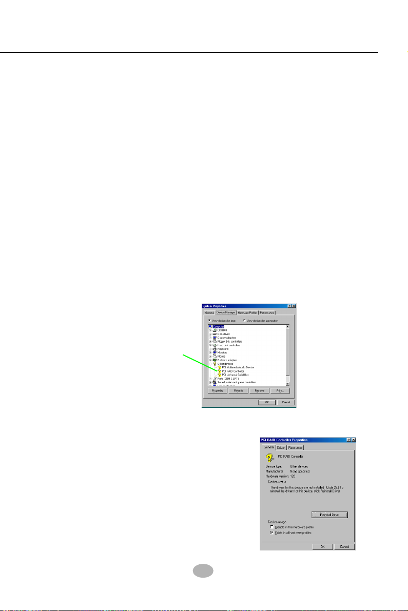
Chapter 5 RAID & RAID Driver
5-12-2 To Install RAID Driver on Windows 98SE/Me
(1) Get ready the Floppy Diskette holding the RAID Driver.
(2) Check that Hard Disks are connected properly to the RAID conn ectors.
(3) Start your system and use RAID BIOS Setup Utility to configure
RAID 0 / 1/ 0+1 to the hard disks.
(4) Restart System and format the bootable hard disks.
(5) Now, apply the Windows 98SE/ME CD to CD-ROM for
operating system installation.
(6) With the Windows 98SE/ME installation complete, restart system
for RAID driver setup.
(7) On the “Start” screen of your system, please click to the following
path:
\My Computer\properties\Device manager
(8) In the “Device manager” screen, you can see the item “ PCI RAID
Controller” with a yellow question mark on its left side, which indicates
that the RAID controller is already detected by system but the driver
is not installed yet. Please point to this item with your mouse and
double click on it (or click the “Properties” button).
The question mark here
indicates that RAID
Controller Driver
is not installed yet.
(9) Instantly, the “PCI RAID Controller Properties“ screen shows up.
Please click the “General” bar to continue.
(10) In the “General” screen, click “reinstall
Driver” button to continue. Please note that
the status of “Device Usage” should stay at
“Exists in all hardware profiles”.
93
Page 91

K8AV-R
(11) In the “Update device Driver Wizard” screen, click “Next” to continue
until you see a dialog box asking you to “Specify a location” for the
driver.
Diskette into CD-ROM/Drive A.
(12) As illustrated in the picture below, check the item “Specify a location”
and click the “Browse” button to find out the correct path for the
driver. As the RAID Driver is in Drive A, please type into the blank
bar the correct path and click “Next” to continue:
D:\Driver\Promise\PDC20376&378\Win98-me
or
A:\Win98-me
(13) The Update Device Driver Wizard will then go on installing the
driver. In a few seconds, installation completes. Please click the “Finish” button on the screen to complete the installation.
You should now insert the SATA/SATA RAID Driver CD/
94
Page 92

Chapter 5 RAID & RAID Driver
Memo
95
 Loading...