

Page 1

SL-B8E-FG / B8E-FGR
Contents
Chapter 1 Specification ............................................. 8
1-1 SL-B8E-FG/FGR Mainboard Layout ...................................9
1-2 Mainboard Specifications .................................................... 10
1-2.1 CPU Socket ...................................................................................10
1-2.2 System Chipsets ........................................................................... 10
1-2.3 AMI BIOS .....................................................................................10
1-2.4 Memory ......................................................................................... 11
1-2.5 Integrated Multiplexed AGP and DVO Interface.................. 11
1-2.6 Multi-I/O Functions .................................................................... 11
1-2.7 Advanced System Power Management .................................... 12
1-2.8 Gigabit LAN on board ................................................................ 12
1-2.9 Hardware Monitor on board ..................................................... 12
1-2.10 8-channel AC’97 Audio Codec ALC850 on board .............. 12
1-2.11 Front Audio-out Connector...................................................... 12
1-2.12 1394A-- high performance serial bus..................................... 13
1-2.13 Form Factor................................................................................ 13
1-3 Mainboard Specification Table ........................................... 14
1-4 Chipset System Block Diagram........................................... 15
Chapter 2 Hardware Setup..................................... 16
2-1 CPU Installation with Socket 478B .................................... 17
2-1.1 To Identify a Pentium 4 CPU..................................................... 17
2-1.2 CPU Installation with Socket 478B ..........................................18
2-2 Pentium 4 CPU Fan Installation ......................................... 19
2-3 Memory Installation ............................................................. 20
2-3.1 Dual-Channel DIMM Installation ............................................20
2-3.2 To Remove a DIMM ....................................................................20
2-4 VGA / AGP 8X/4X Slot Installation.................................... 21
4
Page 2

Contents
2-5 IDE Connector Installation ................................................. 23
2-6 Floppy Drive Connector Installation ................................. 24
2-7 Serial ATA Connectors Installation .................................... 25
2-8 ATX V2.03 Power Supply Installation ............................... 26
2-9 Jumper Settings ..................................................................... 27
2-9.1 JFSB1 & JFSB2: CPU Frequency Select................................. 28
2-9.2 JBAT1: Clear CMOS .................................................................. 29
2-9.3 JKB1: KB / Mouse Wake Up ..................................................... 29
2-10 Other Connectors Configuration...................................... 30
2-10.1 On Board Fan Connectors .......................................................30
2-10.2 USB Ports and USB Pin-headers ............................................31
2-10.3 Complex Pin-header (Front Panel Connectors)................... 32
2-10.4 Back Panel Connectors............................................................. 33
2-10.5 RJ45 LAN Connector................................................................ 33
2-10.6 PS/2 Mouse And PS/2 Keyboard ............................................. 34
2-10.7 CD-ROM Audio Connectors.................................................... 34
2-10.8 System Buzzer: BZ1 .................................................................. 35
2-10.9 JAUD1: Front Panel Audio Connector .................................. 35
2-10.10 RT1: Thermal Resistor........................................................... 36
2-10.11 1394A Front Connector : IEEE1........................................... 36
2-10.12 Printer Port: JPNT1 (optional)............................................. 37
Chapter 3 Software Setup ....................................... 38
3-1 To Open up the Support CD ................................................ 39
3-2 Intel Chipset Software Installation Utility........................ 40
3-3 Graphics Driver Installation ............................................... 41
3-4 AC’97 Audio Driver Installation......................................... 42
3-4.1 Installing AC’97 6-channel Audio Driver ............................... 42
3-4.2 Verifying 6-channel Audio ........................................................43
3-5 To Install RTL8110S Gigabit Ethernet Drivers ............... 45
5
Page 3

SL-B8E-FG / B8E-FGR
3-6 IAA RAID Driver (for Win2000/XP only) ......................... 46
3-7 To Install Hardware Monitor Utility.................................. 47
3-7.1 Installation ................................................................................... 47
3-7.2 Verification .................................................................................. 48
3-8 To Install USB 2.0 Driver for Windows 2000/XP ............. 49
Chapter 4 AMI BIOS Setup.................................... 50
4-1 About BIOS Setup ................................................................. 51
4-2 To Run BIOS Setup ............................................................... 51
4-3 About CMOS .......................................................................... 51
4-4 The POST ( Power On Self Test ) ....................................... 51
4-5 To Update BIOS ..................................................................... 52
4-6 BIOS SETUP --- CMOS Setup Utility................................ 53
4-6.1 CMOS Setup Utility ....................................................................53
4-6.2 Standard BIOS Features ............................................................55
4-6.3 Advanced BIOS Features ........................................................... 56
4-6.3.1 CPU Configuration................................................................... 57
4-6.3.2 IDE Configuration.................................................................... 58
4-6.3.3 Floppy Configuration ............................................................... 60
4-6.3.4 Super IO Configuration ...........................................................61
4-6.3.5 Hardware Health Configuration............................................. 62
4-6.3.6 ACPI Configuration ................................................................. 63
4-6.3.7. Power Management ................................................................. 64
4-6.3.8. USB Configuration .................................................................. 65
4-6.3.9 Frequency/Voltage Control...................................................... 66
4-6.3.10 B8E Onboard Device .............................................................. 66
4-6.4 Advanced Chipset Features ....................................................... 67
4-6.4.1 NorthBridge Configuration ..................................................... 67
4-6.4.2 SouthBridge Configuration ..................................................... 69
4-6.5 PCI/PNP Resource Management .............................................. 69
4-6.5 PCI/PNP Resource Management .............................................. 70
4-6.6 Boot Configuration Features ..................................................... 72
6
Page 4

Contents
4-6.6.1 Boot Settings Configuration .................................................... 72
4-6.6.2 Boot Device Priority/Removable Drives/CD/DVD Drives .... 73
4-6.7. Boot Security Features .............................................................. 74
4-6.7.1. Supervisor Password ...............................................................74
4-6.7.2. User Password.......................................................................... 74
4-6.7.3 Change Supervisor Password .................................................. 74
4-6.7.4 Change User Password ............................................................ 75
4-6.7.5. Clear User Password ............................................................... 76
4-6.7.6 Boot Sector Virus Protection ................................................... 76
4-6.8 Load Optimal Defaults ............................................................... 77
4-6.9 Discard Changes ..........................................................................77
4-6.10 Discard Changes ( and Exit )................................................... 77
4-6.11 Save Changes and Exit.............................................................. 77
Chapter 5 SATA RAID Setup ................................. 78
5-0 About Disk Array................................................................... 79
5-0-1 Disk Array Interpretation.......................................................... 79
5-0-2 Disk Array Member .................................................................... 79
5-0-3 Disk Array Types Supported by ICH5R .................................79
5-1 Enable SATA RAID in System BIOS ................................. 80
5-2 To Enter Intel RAID BIOS Utility Setup........................... 81
5-3 To Create Disk Array ............................................................ 82
5-4 To Install SATA RAID Driver .............................................. 85
5-4-1 To Install SATA RAID Driver on Windows 2000/XP............ 85
5-4-2 To run Windows 98SE/ME without ICH5R RAID driver .. 88
7
Page 5

SL-B8E-FG / B8E-FGR
Chapter 1 Specification
Introduction
This series of mainboards features an integration of the powerful processor Intel Pentium 4 and the North Bridge Intel 865G. The Intel P4
processor is a rapid execution engine supporting 800/533/400MHz system bus, while North Bridge Intel 865G is a high performance integrated
chipset providing Dual Channel DDR 400/333/266 SDRAM memory
interface, Hub interface, AGP interface as well as an integrated Graphics Port for VGA display.
Integrated with i865G, South Bridge Intel ICH5/ICH5R supports the
LPC I/O, upstream Hub interface, PCI interface, IDE interface, SerialATA /SATA RAID, USB 2.0 interface, and interrupt control. (The difference between ICH5 and ICH5R is the RAID interface support). And the
8-channel Audio support is also integrated via the on-board chip ALC850.
This chapter is to introduce to users every advanced function of this
high performance integration.
Topics included in this chapter are:
1-1 Mainboard Layout
1-2 Mainboard Specifications**
1-3 Mainboard Specification Table
1-4 Chipset Diagram
** If any difference is found between the mainboard description
and the Mainboard you are using, please look up the
Update Slip enclosed inside for the correction or updated
information, or else contact the mainboard Dealer or visit our
Web Site for the latest manual update.
8
Errata/
Page 6
Chapter 1 Specification
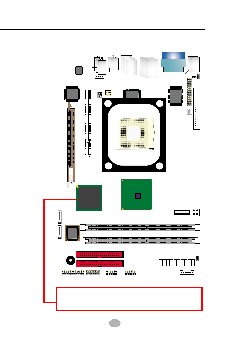
1-1 SL-B8E-FG/FGR Mainboard Layout
A
G
V
PS/2
1
M
VCO
(on top)
)
Winbond
W83627THF
PS/2 K/B
(underside)
Mouse
(on top)
RT1
1
JKB1
JPNT1
RTL
ALC850
VIA
VT6307S
AC'97
r
fe
r/
t
u
O
e
in
L
(
u
n
d
e
e
id
)
r
s
L
e
id
S
d
)
id
le
(M
(on top)
CD-IN1
1
JFSB2
o
o
te
w
n
b
1
3
9
4
e
C
In
e
in
e
R
a
r
S
p
e
a
e
k
r
1
Fan1
JFSB1
A
u
(on top)
S
o
S
B
U
2
p
(2
RTL
8110S
RJ45
(on top)
)
rts
S
B
U
1
(2
o
rts
p
1
PCI 1
AGP1 ( 8X/4X)
Fan2
mPGA478B
FDC1
Intel
IC
H
5
o
r
IC
H
5
R
A
T
A
1
A
T
A
2
I
B
BZ1
HDD
IR
LED
+
-
2
NJ1
1
SPK RST
DIMM1
S
O
DIMM2
PWR
2
JAUD1
1
+
-
PWLED
1
USB4
1
Intel
Intel RG
82845
i865G
DDR 400/333/266/200 MHz
IDE2
IDE1
USB3
1
(+12V Power)
Battery
PW1 (Main Power)
IEEE1
PW2
JBAT1
1
1
South Bridge Option:
ICH5 for SATA interface in SL-B8E-FG;
ICH5R forSATA RAID interface in SL-B8E-FGR
9
Page 7

SL-B8E-FG / B8E-FGR
1-2 Mainboard Specifications
1-2.1 CPU Socket
CPU Socket 478B on board, supporting Intel® Pentium 4 processors
(including Hyper-Threading and Prescott CPUs) in 478-pin package :
(Willamette 1.75V and Celeron 1.75V CPUs not supported)
-- 800/533/400MHz System Bus;Hyper-pipelined technology;
-- Advanced dynamic execution;Advanced transfer cache;
1-2.2 System Chipsets
North Bridge Intel 865G:
• A high performance integrated chipset providing P4 processor interface
(including Hyper-threading Technology), 800/533/400MHz FSB, Dual
-channel DDR 400/333/266 SDRAM memory, Hub interface, AGP in-
terface as well as another integrated VGA interface with one on-board
display port.
• Showing Hyper-Threading Logo when booting with Hyper-threading
CPU
South Bridge Intel ICH5 for SL-B8E-FG:
• Supporting the LPC I/O, upstream Hub interface, PCI interface, IDE
interface, Serial ATA interface, USB 2.0 interface, the 8-channel AC’97
V2.3 Audio interface (with ALC850) and the interrupt control
South Bridge Intel ICH5R for SL-B8E-FGR:
• Supporting the LPC I/O, upstream Hub interface, PCI interface, IDE
interface, Serial ATA/SATA RAID interface, USB 2.0 interface, 8-chan-
nel AC’97 2.3 (with ALC850) Audio interface and the interrupt control
1-2.3 AMI BIOS
Flash Memory for easy upgrade, supporting BIOS Writing Protection,
Year 2000 compliant, and supporting various hardware configuration
during booting system (See Chapter 4 BIOS Setup):
• Standard BIOS Features(Times, Date, System Information etc.)
• Advanced BIOS Features (CPU,IDE, Floppy, SuperIO, Hardware
Health, ACPI, USB, and Frequency/Voltage Control)
• Advanced Chipset Features (NorthBridge, SouthBridge Configuration)
• PCI/PNP Resource Management (IRQ Settings, Latency Timers etc.)
• Boot Configuration Setup (Boot Settings, Boot Device Priority etc.)
• BIOS Security Features (Supervisor Password, User Password)
10
Page 8

Chapter 1 Specification
1-2.4 Memory
2 DDR DIMM 184-pin slots on board :
• Supporting unregistered, non-ECC Dual-channel DDR 400/333/266
SDRAM to 2GBs
• DIMMs to be populated in identical pairs for Dual-channel operation
• SPD (Serial Presence Detect) Scheme for DIMM Detection supported
1-2.5 Integrated Multiplexed AGP and DVO Interface
Integrated multiplexed AGP and DVO interface in Springdale-G,supporting AGP performance and analog/Digital display:
• One AGP slot on board, supporting both Digital Video Out card or
AGP8x/4x card for analog/digital display (TMDS,LVDS and TV-out)
(See AGP Installation in Chapter 2 of this manual)
• One 15-pin VGA connector on board, supporting analog display
• Hardware motion compensation for software MPEG/DVD decode
• Integrated 2D/3D graphics accelerator
• VGA Driver enclosed in Support CD for user’s installation
1-2.6 Multi-I/O Functions
• Serial ATA Controller integrated in ICH5, supporting:
-- 2 Serial ATA connectors supporting up to 150MByte/s transfer rate
• Serial ATA RAID Controller integrated in ICH5R, supporting:
-- 2 SATA/SATA RAID connectors supporting up to 150MByte/s transfer rate
• PCI EIDE Controller, supporting:
-- 2 UATA100/66/33 IDE connectors supporting up to 4 IDE devices
• Dedicated IR Functions:
-- Third serial port dedicated to IR function either through the two
complete serial ports or the third dedicated port Infrared-IrDA (HPSIR)
and ASK (Amplitude Shift Keyed) IR
• Multi-mode Parallel Data Transfer:
-- Standard mode, high speed mode ECP and enhanced mode EPP
• Floppy Disk Connector:
-- 1 FDD connector supporting 2 floppy drives with drive swap support
• Universal Serial Bus Transfer Mode:
-- USB V2.0 compliant; 480Mb/s USB Bus, supporting Windows 2000 or
later operating systems (no support for Win 9X/Me)
-- 4 built-in USB Ports and 2 USB Headers which require 2 additional
USB cables to provide 4 more optional USB ports
• PS/2 Keyboard and PS/2 Mouse
• UARTs (Universal Asynchronous Receiver / Transmitter):
-- 1 serial ports on board
11
Page 9

SL-B8E-FG / B8E-FGR
1-2.7 Advanced System Power Management
• ACPI 1.0B compliant (Advanced Configuration and Power Interface),
including ACPI suspend mode support (See ACPI Configuration of
Advanced BIOS Features in BIOS Setup)
• APM V1.2 compliant (Legacy Power Management)
• Keyboard / Mouse Power On/Wake Up (See ACPI Configuration of
Advanced BIOS features in BIOS Setup)
• Supporting Wake-on-LAN
• Supporting Real Time Clock (RTC) for date alarm, month alarm, and
century field configuration
1-2.8 Gigabit LAN on board
PCI local bus Gigabit Fast Ethernet Controller RTL8110S on board:
• Supporting 10/100/1000Mb data transfer
• Supporting Wake On LAN function through the on-board RJ45 LAN
Connector
• LAN Driver enclosed in Support CD for user’s installation.
1-2.9 Hardware Monitor on board
• Hardware Monitor supported by W83627THF, providing monitoring
and alarm for flexible desktop management of hardware voltage, tem-
peratures and fan speeds.
• Utility Software Soltek Hardware Monitor for displaying system status
is enclosed in Support CD for user’s installation.
1-2.10 8-channel AC’97 Audio Codec ALC850 on board
ALC850 on board for AC’97 audio
• Supporting 8-channel display of PCM audio output
• 8 channel audio consists of Front Left, Front Right, Back Left, Back
Right, Rear Left, Rear Right, Center and Subwoofer for complete
surround sound effect
• AC’97 Audio Codec Driver enclosed in Support CD for user’s
installation
1-2.11 Front Audio-out Connector
• 1 Front Audio-out connector supporting Front Panel S/PDIF Output,
Front Panel Mic-In and Front Panel Line-out
• This Front Audio-out distinguishing itself from the Back Panel Audio
Connectors
12
Page 10

Chapter 1 Specification
1-2.12 1394A-- high performance serial bus
1394A Interface, via VT6307 PCI PHY/Link Open Host Controller:
• PCI-bus based open host controller, compliant with IEEE 1394A-2000
standard for high performance serial bus
• supporting 2x 1394A ports, each supporting 400/200/100 Mbits transfer
rate
1-2.13 Form Factor
• Soltek Mini Form Factor, ATX Power Supply, version 2.03 compliant,
supported by 1x Main Power Connector, 1x +12V Power Connector.
• Mainboard size: 180mm x 270mm
13
Page 11

SL-B8E-FG / B8E-FGR
1-3 Mainboard Specification Table
B8E-FG/B8E-FGR Specifications and Features
Socket 478B for P4 CPU (Hyper-threading and
CPU
North Bridge
South Bridge
Prescott CPUs included; Willamette 1.75V and
Celeron 1.75V CPUs not supported)
Intel 865G, supporting 800/533/400MHz FSB
Intel ICH5 for B8E-FG; ICH5R for B8E-FGR
Memory
I/O Chip
AGP interface
Audio
IDE Interface
PCI Slots
I/O Connectors
Networking
VGA Display
1394A Interface
Other common
features
Optional features
South Bridge
Supporting Dual-channel DDR 400/333/266
SDRAM, up to 2GB in 2 DIMM slots
W83627THF, with Soltek Hardware Monitor
AGP8X/4X Mode only; 1 AGP Slot on board
AC’97 Audio Codect ALC850, 8-channel audio
2 UATA 66/100 IDE ports
1 PCI Master slots on board
8 USB V2.0, 1 FDD port, 1 COM ports, 1 LPT,
1 IrDA, 1 PS/2 K/B, 1 PS/2 Mouse
Gigabit LAN Controller RTL8110S and RJ45
1 x VGA connector on board for analog display
Built-in 1394A Interface, supporting 2x 1394A
Ports
Keyboard/Mouse Wake Up
ATX 2.03 Power Supply
Soltek Mini Form Factor
B8E-FG B8E-FGR
ICH5
(No SATA RAID
Interface)
ICH5R (with
SATA RAID
Interface)
14
Page 12

Chapter 1 Specification
1-4 Chipset System Block Diagram
Intel Pentium 4 CPU
(Hyper-Threading and Prescott
CPUs Included)
System Bus 800/533/400MHz
VGA
Connector
AGP Slot
DVO(digital)
TV Out
AGP 8X/4X
card
2 IDE
Connectors
2 SATA/RAID
ports
2 SATA ports
USB
Ports
Mouse/Keyboard
FDD
Serial Ports
Printer Port
H/Monitor
Smart Fan
VGA
Interface
AGP 8X/4X
ATA 100/66/33
SATA RAID
(ICH5R only)
Serial ATA
(ICH5)
USB Bus V2.0
IR
LPC I/O
W83627THF
Intel
i865G
North Bridge
266MB/s
Hub Interface
ICH5
(82801EB)
or
ICH5R
82801ER
South
Bridge
Dual-channel
DDR memory
Interface
DDR 400/333/
266 SDRAM;
PCI Slot
PCI Bus
RTL8110S
Gigabit LAN,
10/100/1KMb
ALC850 Audio Codec
(8-channel)
System
Memory
1394A
VT6307S
RJ45
S/PDIF in/out
BIOS
Pentium 4 + Intel i865G + Intel ICH5/ICH5R Diagram
15
Page 13

SL-B8E-FG / B8E-FGR
Chapter 2 Hardware Setup
To Get Things Ready for Hardware Setup !
1. We recommend to install your CPU before any other components.
For detailed installation instructions of processor, you can also refer
to the pamphlet enclosed in your CPU package.
2. Installing a cooling fan with a good heat sink is a must for proper
heat dissipation for your CPU. Get ready an appropriate fan with
heat sink for proper installation. Improper fan and installation will
damage your CPU.
3. In case CPU Vcore, CPU clock or Frequency Ratio is adjustable on
board, please follow the instructions described in the User’s manual
for proper setup. Incorrect setting will cause damage to your CPU.
The following topics are included in this chapter:
2-1 CPU Installation with Socket 478B
2-2 Pentium 4 CPU Fan Installation
2-3 Memory Installation
2-4 VGA / AGP 8X/4X Slot Installation
2-5 IDE Connectors Installation
2-6 Floppy Drive Connector Installation
2-7 SATA /RAID Connectors Installation
2-8 ATX V2.03 Power Supply Installation
2-9 Jumper Settings
2-10 Other Connectors Configuration
16
Page 14

Chapter 2 Hardware Setup
2-1 CPU Installation with Socket 478B
2-1.1 To Identify a Pentium 4 CPU
Intel
pentium 4
2.4 GHz / 512 / 533 / 1.5V
4) CPU Voltage Vcore
3) System Clock
2) CPU L2 Cache
1) CPU Working Frequency
On the heatsink side of a Pentium 4 CPU, there printed a line of figures
to identify its specifications. The line consists of 4 parts:
1. CPU Working Frequency: this part depicts the working frequency of
the CPU. For example,
2.4 GHz depicts that this CPU is locked to 2.4 GHz working frequency
(18 x 133MHz CPU clock);
2A GHz depicts that this CPU is an A version, locked to 2.0 GHz
working frequency (20 x 100MHz CPU clock)
3.06GHz depicts that this is a 3.06GHz hyper-threading CPU
2. CPU L2 Cache: this part depicts the L2 Cache size. For example,
512 stands for 512 KB L2 Cache; 256 stands for 256 KB L2 Cache
3. System Clock: this part depicts the System Clock (Front Side Bus)
provided by the CPU. For example,
533 stands for a 533MHz system clock provided by a 133MHz CPU
times 4;
400 stands for a 400 system clock provided by a 100 MHz CPU x 4.
4. CPU Voltage Vcore: this part depicts the CPU Voltage. For example,
1.5V stands for a CPU of 1.5V Vcore.
Note: System Clock vs CPU Clock
P4 CPU is a quadpumped CPU. The system bus is provided by
the CPU clock x 4. Therefore, users can figure out the P4 CPU
clock by the System Clock divided by 4.
17
Page 15

SL-B8E-FG / B8E-FGR
mPGA478B
In
te
l P
e
n
tiu
m
4
2-1.2 CPU Installation with Socket 478B
This mainboard is built with CPU
Socket 478B ( 478-pin) supporting
the Intel Pentium 4 CPU:
• After installation of Pentium 4 CPU,
you must also install the specific
Pentium 4 CPU fan designed in
tandem with this CPU. This CPU
Fan installation is described in next
section.
• This mainboard supports Hyperthreading dual-in-one CPU, the
function of which can be enabled
by Windows XP. (See illustration
on the right.)
( If Hyper-threading CPU is
installed successfully with O/S
Win XP, the O/S will enable the
dual-in-one CPU function.)
1. First pull sideways the lever of
Socket 478, and then turn it up
0
so as to raise the upper layer
90
of the socket from the lower
platform.
mPGA478B
Pin 1
2. Configure Pin 1 of CPU to Pin 1
of the Socket, just as the way
shown in the diagram on the
right. Adjust the position of CPU
until you can feel all CPU pins
get into the socket with ease.
3. Make sure that all CPU pins have
completely entered the socket
and then lower down the lever
to lock up CPU to socket.
18
Pin 1
4
m
tiu
n
e
l P
te
In
m
P
G
A
4
7
8
B
Page 16
Chapter 2 Hardware Setup
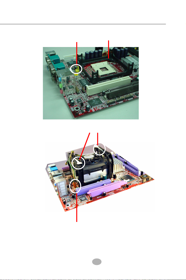
2-2 Pentium 4 CPU Fan Installation
CPU Fan Connector Pentium 4 Fanbase
Press down the spring locks to lock up the fan
Connect Cooling Fan cable
to CPU FAN connector
The above pictures are taken from sample mainboards as installation illustration. The layout in the pictures may be different from your mainboard.
19
Page 17

SL-B8E-FG / B8E-FGR
R
T
L
P
C
I
1
D
IM
M
1
F
D
C
1
ID
E
1
ID
E
2
P
W
2
P
W
1
(
M
a
in
P
o
w
e
r
)
B
I
O
S
D
IM
M
2
D
D
R
4
0
0
/3
3
3
/2
6
6
/2
0
0
M
H
z
A
G
P
1
(
8
X
/4
X
)
m
P
G
A
4
7
8
B
V
IA
V
T
6
3
0
7
S
Intel RG82845
i8
6
5
G
In
te
l
B
Z
1
B
a
tt
e
r
y
N
J
1
SPK
R
S
T
P
W
L
E
D
H
D
D
IR
P
W
R
1
2
+
-
+
-
L
E
D
R
T
L
A
L
C
8
5
0
A
C
'9
7
C
D
-
I
N
1
U
S
B
3
F
a
n
1
F
a
n
2
1
J
F
S
B
2
U
S
B
4
A
T
A
1
A
T
A
2
1
J
F
S
B
1
1
J
B
A
T
1
1
J
K
B
1
W
8
3
6
2
7
T
H
F
W
in
b
o
n
d
P
S
/
2
P
S
/
2
K
/
B
(
u
n
d
e
r
s
i
d
e
)
V
G
A
J
P
N
T
1
1
L
i
n
e
I
n
L
i
n
e
O
u
t
S
i
d
e
(
o
n
t
o
p
)
(
u
n
d
e
r
s
i
d
e
)
(
M
i
d
d
l
e
)
R
J
4
5
U
S
B
1
(
2
p
o
r
t
s
)
(
o
n
t
o
p
)
V
C
O
M
1
(o
n
to
p)
R
T
1
(
o
n
t
o
p
)
M
o
u
s
e
8
1
1
0
S
(+
1
2
V
P
o
w
e
r
)
IC
H
5R
In
te
l
1
1
U
S
B
2
(
2
p
o
r
t
s
)
(
o
n
t
o
p
)
JAUD1
1
1
2
R
e
a
r
S
p
e
a
k
e
r
C
e
n
t
e
r
/
S
u
b
w
o
o
f
e
r
1
3
9
4
A
1
IE
E
E
1
IC
H
5
or
2-3 Memory Installation
How to tackle the memory Modules:
• Make sure to unplug your power supply before adding or removing
memory module.
• Pay attention to the orientation of the DIMM slots.
2-3.1 Dual-Channel DIMM Installation
• Dual Channel memory configuration provides higher performance than
Single Channel configurations
• Matched DIMMs with identical density, DRAM technology, DRAM bus
width, and equal number of memory banks are needed .
• This series supports up to 2GB unbuffered Dual-channel DDR 400/
333/266 SDRAM, with 2 DDR DIMM slots on board.
other type of modules into these slots.
• The dual memory controller can double the DDR memory bandwidth
up to 6.4GB/s with DDR400, 5.4GB/s with DDR333 and 4.2GB/s with
DDR266.
• To enable Dual-channel memory function, users should insert totally
identical (size and frequency) DDR module pair into the bank-pair.
• DDR DIMM slot has 184 pins and one notch. Insert a DDR SDRAM
vertically into the 184-pin slot with the notch-to-rib matching.
Do not insert
184-Pin DIMM Notch Key Definitions
DRAM Key Position Voltage Key Position
DDR Rib
2-3.2 To Remove a DIMM
Power off the system first, and then press down the holding latches on
Module Latch
(2.5V Voltage Key)DDR Notch
both sides of slot to release the module from the DIMM slot.
20
Page 18

Chapter 2 Hardware Setup
RTL
PCI 1
DIMM1
FDC1
IDE1
IDE2
PW2
PW1 (Main Power)
B
I
O
S
DIMM2
DDR 400/333/266/200 MHz
AGP1 ( 8X/4X)
mPGA478B
VIA
VT6307S
Intel R
G82845
i865G
Intel
BZ1
Battery
NJ1
SPK RST
PWLED
HDD
IR
PWR
1
2
+
-
+
-
LED
RTL
ALC850
AC'97
C
D
-
I
N
1
USB3
F
a
n
1
F
a
n
2
1
JFSB2
USB4
A
T
A
1
A
T
A
2
1
JFSB1
1
JBAT1
1
JKB1
W83627THF
Winbond
P
S
/
2
P
S
/
2
K
/
B
(
u
n
d
e
r
s
i
d
e
)
V
G
A
JPNT1
1
L
i
n
e
I
n
L
i
n
e
O
u
t
S
i
d
e
(
o
n
t
o
p
)
(u
n
d
e
rs
id
e
)
(M
id
d
le
)
R
J
4
5
U
S
B
1
(2
p
o
rts
)
(
o
n
t
o
p
)
V
C
O
M
1
(on top)
RT1
(
o
n
t
o
p
)
M
o
u
s
e
8110S
(+12V Power)
IC
H
5
R
In
te
l
1
1
U
S
B
2
(2
p
o
rts
)
(
o
n
t
o
p
)
JA
U
D
1
1
1
2
R
e
a
r
S
p
e
a
k
e
r
C
e
n
te
r/
S
u
b
w
o
o
fe
r
1
3
9
4
A
1
IEEE1
IC
H
5
o
r
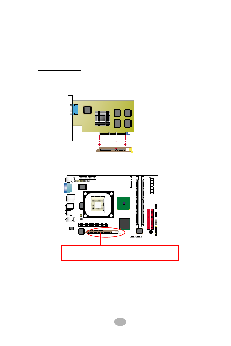
2-4 VGA / AGP 8X/4X Slot Installation
1. To install on-board VGA, please connect your monitor directly to VGA
connector on board.
2. To install Digital-Video-Out(DVO) / TV Out display, please insert an
AGP / DVO /TV Out card into the AGP slot. This AGP slot supports
AGP 8X/4X card(analog), DVO card and TV Out card, respectively
but not simultaneously.
TV Out Display
(analog)
DVI Cable
DVO Card
DVI
Connector
LCD (digital)
Monitor
VGA
Connector
Insert an AGP 8X/4X card / DVO / TV Out card to
Analog
AGP slot for AGP / DVO / TV Out Display
Monitor
21
Page 19
SL-B8E-FG / B8E-FGR
RTL
PCI 1
DIMM1
FDC1
IDE1
IDE2
PW2
PW1 (Main Power)
B
I
O
S
DIMM2
DDR 400/333/266/200 MHz
AGP1 ( 8X/4X)
mPGA478B
VIA
VT6307S
Intel R
G
82845
i865G
Intel
BZ1
Battery
NJ1
SPK RST
PWLED
HDD
IR
PWR
1
2
+
-
+
-
LED
RTL
ALC850
AC'97
C
D
-
I
N
1
USB3
F
a
n
1
F
a
n
2
1
JFSB2
USB4
A
T
A
1
A
T
A
2
1
JFSB1
1
JBAT1
1
JKB1
W83627THF
Winbond
P
S
/
2
P
S
/
2
K
/
B
(
u
n
d
e
r
s
i
d
e
)
V
G
A
JPNT1
1
L
i
n
e
I
n
L
i
n
e
O
u
t
S
i
d
e
(
o
n
t
o
p
)
(u
n
d
e
rs
id
e
)
(M
id
d
le
)
R
J
4
5
U
S
B
1
(2
p
o
rts
)
(
o
n
t
o
p
)
V
C
O
M
1
(on top)
RT1
(
o
n
t
o
p
)
M
o
u
s
e
8110S
(+12V Power)
IC
H
5
R
In
te
l
1
1
U
S
B
2
(2
p
o
rts
)
(
o
n
t
o
p
)
JA
U
D
1
1
1
2
R
e
a
r
S
p
e
a
k
e
r
C
e
n
te
r/
S
u
b
w
o
o
fe
r
1
3
9
4
A
1
IEEE1
IC
H
5
o
r
3. If user wants AGP display, please insert 1.5V AGP 8X/4X card into
the AGP slot to boot system. A Rib is specifically added to the 8X/4X
slot so as to match the AGP 8X/4X card.
card into the AGP 8X/4X slot will damage the system chip and burn
the 1.5V circuitry.
An AGP 8X card will support a data transfer rate up to 2GB/sec,
while an AGP 4X card will provide 1GB/sec transfer rate.
AGP Accelerator
notch
To insert a 3.3V AGP 2X
AGP 8X/4X Slot
Insert an AGP 8X/4X card / DVO / TV Out card to
AGP slot for AGP / DVO / TV Out Display
22
Page 20
Chapter 2 Hardware Setup
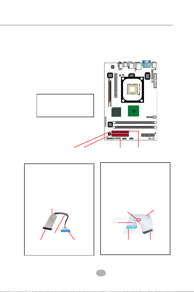
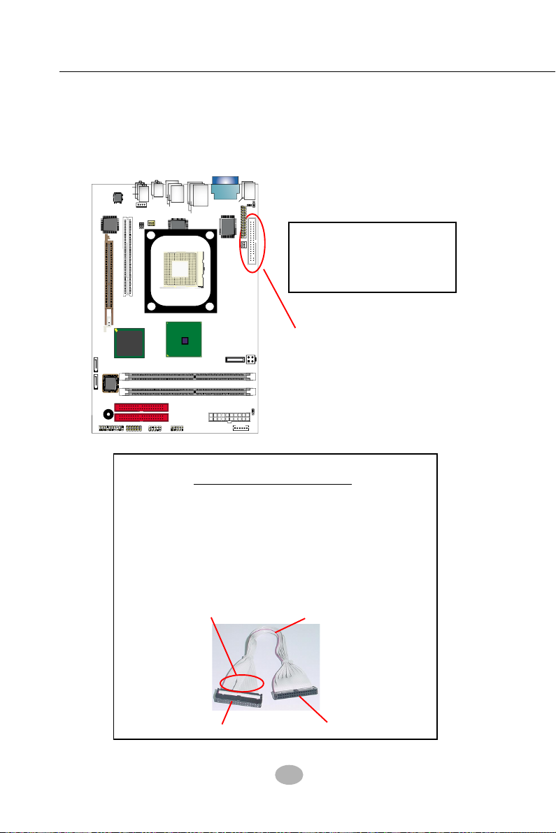
2-5 IDE Connector Installation
IDE1 and IDE2 are 2 IDE connectors supporting 4 IDE devices for up to
133MB/s data transfer.
A
G
1
3
9
4
o
t
n
o
o
p
rts
RTL
8110S
Intel
i865G
V
2
/
S
P
1
M
O
C
V
e
s
u
o
5
4
)
p
o
t
)
r
ts
(on top)
K
/
P
S
2
/
d
r
s
i
e
d
n
(
u
Winbond
W83627THF
Battery
PW1 (Main Power)
IEEE1
B
)
e
1
2
n
a
F
M
o
(
RT1
PW2
(+12V Power)
)
p
o
t
n
1
JKB1
JPNT1
FDC1
JBAT1
1
1
A
J
R
)
p
n
o
(
)
S
U
B
1
(
2
o
p
mPGA478B
G82845
Intel R
USB3
IDE1 / IDE2
Hard Disk Drive Connector
Orient the red line on the IDE
Flat Cable to Pin1.
r
fe
r/
o
e
n
O
i
L
t
u
o
te
(u
n
d
e
e
id
rs
)
w
n
b
e
u
C
L
n
i
e
I
n
e
d
S
i
(
(M
AGP1 ( 8X/4X)
In
IC
IC
H
PWR
2
+
-
PWLED
1
id
o
d
le
te
H
r
DIMM1
DIMM2
JA
1
)
PCI 1
l
5
5
R
U
D
)
p
o
t
n
o
(
e
R
a
r
S
p
e
a
k
1
N
I
-
D
C
1
1
F
JFSB1
JFSB2
1
USB4
1
S
e
r
S
U
B
2
(2
1
a
n
DDR 400/333/266/200 MHz
IDE2
IDE1
1
RTL
AC'97
ALC850
VIA
VT6307S
A
T
A
1
A
T
A
2
S
O
I
B
BZ1
HDD
LED
IR
+
-
2
NJ1
1
SPK RST
Pin 1 (to Red Line)
80-conductor IDE Cable
(for 2 IDE devices)
This kind of cable is dedicated for Minibarebone system because the ribbon is
bundled up and will not block the air
flow in the barebone cabinet.
Gray connector
(To slave device)
Red line
Black connector
Blue connector
(To Mainboard)(To Master Device)
IDE1
IDE2
80-conductor IDE Cable
(dedicated for 1 IDE device)
This kind of cable is dedicated for Minibarebone system because the ribbon is
bundled up and will not block the air
flow in the barebone cabinet.
Bundle Strap
80-conductor
IDE cable
Blue connector
(To Mainboard)
Red line
Black connector
(To Master Device)
23
Page 21
SL-B8E-FG / B8E-FGR
R
T
L
P
C
I
1
D
IM
M
1
F
D
C
1
ID
E
1
ID
E
2
P
W
2
P
W
1
(
M
a
in
P
o
w
e
r
)
B
I
O
S
D
IM
M
2
D
D
R
400
/333
/266
/200
M
H
z
A
G
P
1
(
8
X
/4
X
)
m
P
G
A
4
7
8
B
V
IA
V
T
6
3
0
7
S
Intel RG82845
i8
6
5
G
In
te
l
B
Z
1
B
a
t
t
e
r
y
N
J
1
S
P
K
R
S
T
P
W
L
E
D
H
D
D
I
R
P
W
R
1
2
+
-
+
-
L
E
D
R
T
L
A
L
C
8
5
0
A
C
'9
7
C
D
-IN
1
U
S
B
3
F
a
n
1
F
a
n
2
1
J
F
S
B
2
U
S
B
4
A
T
A
1
A
T
A
2
1
J
F
S
B
1
1
J
B
A
T
1
1
J
K
B
1
W
8
3
6
2
7
T
H
F
W
in
b
o
n
d
P
S
/2
P
S
/
2
K
/
B
(
u
n
d
e
r
s
i
d
e
)
VGA
J
P
N
T
1
1
L
i
n
e
I
n
L
i
n
e
O
u
t
S
i
d
e
(on top)
(
u
n
d
e
rsi
d
e
)
(
M
i
d
d
l
e
)
RJ45
U
S
B
1
(
2
p
o
r
t
s
)
(on top)
VCOM1
(
o
n
t
o
p
)
R
T
1
(o
n
to
p
)
M
ou
s
e
8
1
1
0
S
(
+
1
2
V
P
o
w
e
r
)
IC
H
5R
In
te
l
1
1
U
S
B
2
(
2
p
o
r
t
s
)
(on top)
J
A
U
D
1
1
1
2
R
e
a
r
S
p
e
a
k
e
r
C
e
n
t
e
r
/
S
u
b
w
o
o
f
e
r
1
3
9
4
A
1
I
E
E
E
1
IC
H
5
or
2-6 Floppy Drive Connector Installation
To install FDC, you should connect the end of FDC cable with single
connector to the board, and connect the other end with two connectors
to the floppy drives.
Floppy Drive Connector:
Orient the red line of the
Floppy Flat Cable to Pin1.
Pin 1 (to Red Line)
34-pin FDC cable
(Dedicated for Barebone)
This kind of cable is dedicated for Mini-barebone
system because the ribbon can be bundled up and
will not block the air flow in the barebone cabinet.
A dedicated cable with 2nd connector for 2nd floppy
drive is an optional item in the Mini-barebone
System.
Signal Swap End
Red line
To 1st Floppy Drive
To mainboard
24
Page 22
Chapter 2 Hardware Setup
RTL
PCI 1
DIMM1
FDC1
IDE1
IDE2
PW2
PW1 (Main Power)
B
I
O
S
DIMM2
DDR 400/333/266/200 MHz
AGP1 ( 8X/4X)
mPGA478B
VIA
VT6307S
Intel R
G
82845
i865G
Intel
BZ1
Battery
NJ1
SPK RST
PWLED
HDD
IR
PWR
1
2
+
-
+
-
LED
RTL
ALC850
AC'97
CD-IN1
USB3
F
a
n
1
F
a
n
2
1
JFSB2
USB4
A
T
A
1
A
T
A
2
1
JFSB1
1
JBAT1
1
JKB1
W83627THF
Winbond
PS/2
P
S
/
2
K
/
B
(
u
n
d
e
r
s
i
d
e
)
V
G
A
JPNT1
1
L
i
n
e
I
n
L
i
n
e
O
u
t
S
i
d
e
(on top)
(u
n
d
e
rs
id
e
)
(M
id
d
le
)
RJ45
U
S
B
1
(2
p
o
rts
)
(on top)
V
C
O
M
1
(
o
n
t
o
p
)
RT1
(on top)
Mouse
8110S
(+12V Power)
IC
H
5
R
In
te
l
1
1
U
S
B
2
(2
p
o
rts
)
(on top)
J
A
U
D
1
1
1
2
R
e
a
r
S
p
e
a
k
e
r
C
e
n
te
r/
S
u
b
w
o
o
fe
r
1
3
9
4
A
1
IEEE1
IC
H
5
o
r
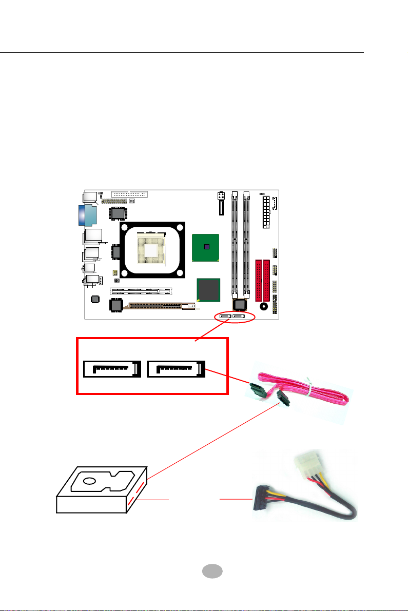
2-7 Serial ATA Connectors Installation
The Serial ATA is designed to improve the Parallel ATA with the capability of Hot Plug and offer a data bandwidth of 150Mbytes/second. It also
reduce voltage and pin count and can be implemented with thin cables
which improve the inner ventilaton of PC cases.
2 Serial ATA connectors are built on board, supported by the SATA Controller for SATA Hard Disk Drives.
Serial ATA Connector ATA1 and ATA2
Serial ATA Cable
To Power Supply
Serial ATA Hard Disk
SATA Power
Connectors
25
Serial ATA Power Cable
(optional)
Page 23
SL-B8E-FG / B8E-FGR
RTL
PCI 1
DIMM1
FDC1
IDE1
IDE2
PW2
PW1 (Main Power)
B
I
O
S
DIMM2
DDR 400/333/266/200 MHz
AGP1 ( 8X/4X)
mPGA478B
VIA
VT6307S
Intel R
G
82845
i865G
Intel
BZ1
Battery
NJ1
SPK RST
PWLED
HDD
IR
PWR
1
2
+
-
+
-
LED
RTL
ALC850
AC'97
C
D
-
I
N
1
USB3
F
a
n
1
F
a
n
2
1
JFSB2
USB4
A
T
A
1
A
T
A
2
1
JFSB1
1
JBAT1
1
JKB1
W83627THF
Winbond
P
S
/
2
P
S
/
2
K
/
B
(
u
n
d
e
r
s
i
d
e
)
V
G
A
JPNT1
1
L
i
n
e
I
n
L
i
n
e
O
u
t
S
i
d
e
(
o
n
t
o
p
)
(u
n
d
e
rs
id
e
)
(M
id
d
le
)
R
J
4
5
U
S
B
1
(2
p
o
rts
)
(
o
n
t
o
p
)
V
C
O
M
1
(on top)
RT1
(
o
n
t
o
p
)
M
o
u
s
e
8110S
(+12V Power)
IC
H
5
R
In
te
l
1
1
U
S
B
2
(2
p
o
rts
)
(
o
n
t
o
p
)
JA
U
D
1
1
1
2
R
e
a
r
S
p
e
a
k
e
r
C
e
n
te
r/
S
u
b
w
o
o
fe
r
1
3
9
4
A
1
IEEE1
IC
H
5
o
r
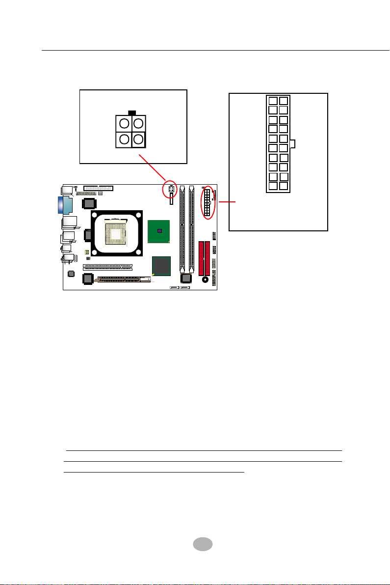
2-8 ATX V2.03 Power Supply Installation
+12V PowerConnector
2
GND
+12V
3
1
GND
+12V
4
+12V
5SB
PWR OK
GND
+5V
GND
+5V
GND
+3.3V
+5V
+5V
-5V
GND
GND
GND
PS ON#
GND
-12V
+3.3V +3.3V
Pin1 Pin11
Main Power Connector
(20-pin)
ATX V2.03 Power Supply is strongly recommended for mainboard running with 2GHz or higher CPU.
To set up Power Supply on this mainboard:
1. Connect the on-board Main Power Connector (20-pin) to the Main
Power Connector (20-pin) of an ATX Power Supply which can be of
the latest version 2.03 model, and then connect the square-shaped
+12V Power Connector on board to the square-shaped +12V Power
Connector of the Power Supply.
Warning: Both the Main Power Connector and the +12V Power
Connector should be connected to Power Supply; otherwise, the
system may either not start or be damaged.
2. This ATX Power Supply should be able to provide at least 720mA/
+5V standby power for Wake On Lan function.
26
Page 24
Chapter 2 Hardware Setup
RTL
PCI 1
DIMM1
FDC1
IDE1
IDE2
PW2
PW1 (Main Power)
B
IO
S
DIMM2
DDR 400/333/266/200 MHz
AGP1 ( 8X/4X)
mPGA478B
VIA
VT6307S
Intel R
G
82845
i865G
Intel
BZ1
Battery
NJ1
SPK RST
PWLED
HDD
IR
PWR
1
2
+
-
+
-
LED
RTL
ALC850
AC'97
C
D
-
I
N
1
USB3
F
a
n
1
F
a
n
2
1
JFSB2
USB4
A
T
A
1
A
T
A
2
1
JFSB1
1
JBAT1
1
JKB1
W83627THF
Winbond
P
S
/
2
P
S
/
2
K
/
B
(
u
n
d
e
r
s
i
d
e
)
VGA
JPNT1
1
L
i
n
e
I
n
L
i
n
e
O
u
t
S
i
d
e
(
o
n
t
o
p
)
(u
n
d
e
rs
id
e
)
(M
id
d
le
)
R
J
4
5
U
S
B
1
(2
p
o
rts
)
(
o
n
t
o
p
)
VCOM
1
(on top)
RT1
(
o
n
t
o
p
)
M
o
u
s
e
8110S
(+12V Power)
IC
H
5
R
In
te
l
1
1
U
S
B
2
(2
p
o
rts
)
(
o
n
t
o
p
)
JAUD1
1
1
2
R
e
a
r
S
p
e
a
k
e
r
C
e
n
te
r/
S
u
b
w
o
o
fe
r
1
3
9
4
A
1
IEEE1
IC
H
5
o
r
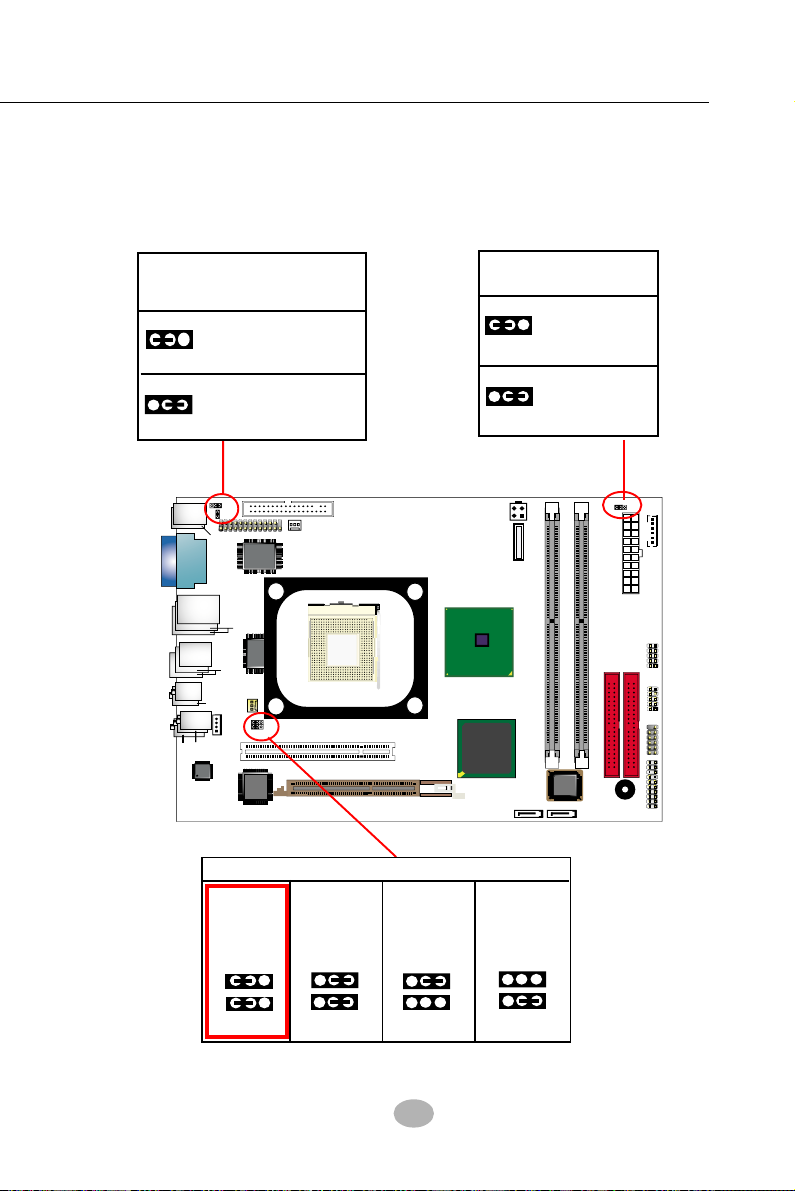
2-9 Jumper Settings
The following diagrams show the locations and settings of jumper blocks
on the mainboard.
KB / Mouse Wake Up
JKB1:
1-2 closed
1
1
Disabled
2-3 closed
Enabled
(default)
Clear CMOS
1
1
JBAT1
1-2 closed (default)
To hold data
2-3 closed
To clear CMOS
JFSB1&JFSB2: CPU Frequency Select
CPU
Auto-Detect
(default)
JFSB1
1
1
JFSB2
(400MHz FSB)
100MHz CPU
Selected
JFSB1
1
1
JFSB2
(533MHz FSB)
133MHz CPU
Selected
JFSB1
1
1
JFSB2
27
(800MHz FSB)
200MHz CPU
Selected
JFSB1
1
1
JFSB2
Page 25
SL-B8E-FG / B8E-FGR
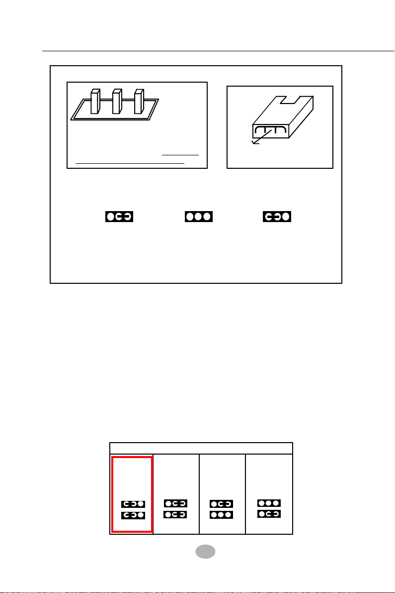
How to tackle the Jumpers:
123
A 3-pin Jumper
If a pin-header (of 2 or more pins) is
designed in such a way that its pins
can be closed or linked together to
set up a specific function,
is called a jumper in this manual.
this header
A 2-pin
Jumper
Cap
The conductor inside the cap
links two header-pins together.
• A Jumper is usually but not necessarily given a “JpX” legend.
• In the Jumper setting diagram, the jumper pins covered with
black marks stand for closed pins with jumper cap.
1 13313
Jp X
Jumper with
Pin 2-3 closed
Jumper with
all pins opened
Jumper with
Pin 1-2 closed
• Do not remove any jumper cap when power is on. Always
make sure the power is off before changing any jumper settings.
Otherwise, the mainboard will be damaged.
2-9.1 JFSB1 & JFSB2: CPU Frequency Select
JFSB1 and JFSB2 are designed on board for CPU frequency select.
1. Setting JFSB1 1-2 closed and JFSB2 1-2 closed will allow CPU on
board to Auto Detect its own frequency and apply it to the System
Bus.
2. Setting JFSB1 2-3 closed and JFSB2 2-3 closed is for 100 MHz CPU.
3. Setting JFSB1 2-3 closed and JFSB2 open is for 133 MHz CPU.
4. Setting JFSB1 open and JFSB2 2-3 closed is for 200MHz CPU. If
200MHz is an overclock for your CPU, it may or may not boot your
system. If an overclok fails to boot system, you should restore the
default setting and then clear CMOS to reboot your system. (See
Clear CMOS in next paragraph.)
JFSB1&JFSB2: CPU Frequency Select
CPU
Auto-Detect
(default)
JFSB1
1
1
JFSB2
(400MHz FSB)
100MHz CPU
Selected
JFSB1
1
1
JFSB2
(533MHz FSB)
133MHz CPU
Selected
JFSB1
1
1
JFSB2
28
(800MHz FSB)
200MHz CPU
Selected
JFSB1
1
1
JFSB2
Page 26

Chapter 2 Hardware Setup
Further Notes on CPU Overclocking:
1. If you have successfully booted system, with or without CPU
overclock, you still can try another CPU overclock in BIOS Setup.
Please enter BIOS Setup, choose “Frequency/Voltage Control” of
Advanced BIOS Features, and configure the “CPU Clock” item to
raise your CPU clock.
2. CPU overclocking should take all components on board into account.
If you fail in BIOS overclocking, you will not be able to restart system.
In such case, Power off system and clear CMOS by JBAT1 and then
restart your system. And remember to reconfigure whatever should
be reconfigured.
3. If your system is already fixed in a cabinet or case, you may not like
to take the trouble to clear CMOS. Then power on your system with
the power button on the PC case and simultaneously press down the
“Insert” key on the keyboard until you see the initial bootup screen
appear. And remember you should also enter CMOS BIOS Setup
instantly and choose “Load Optimized Defaults” to restore default
BIOS .
2-9.2 JBAT1: Clear CMOS
When you have problem with rebooting your
system, you can clear CMOS data and restore
it to default value. To clear CMOS with Jumper
JBAT1, please follow the steps below:
1. Power off system.
2. Set JBAT1 to Pin 2-3 closed.
3. After 2 or 3 seconds, restore the JBAT1
setting to Pin1-2 closed.
4. CMOS data are restored to default now.
Remember never clear
CMOS when system power is on.
2-9.3 JKB1: KB / Mouse Wake Up
JKB1 is designed on board as a jumper to
enable/disable the PS/2 keyboard/mouse
Wake Up from suspend mode. Yet user
should still enter the “ ACPI Configuration”
of BIOS setup to choose the Wake Up
mode.
USB keyboard/mouse Wake Up function is
also supported on this mainboard.
29
JBAT1
Clear CMOS
1-2 closed (default)
To hold data
1
2-3 closed
To clear CMOS
1
KB / Mouse Wake Up
1
1
JKB1:
1-2 closed
Disabled
2-3 closed
Enabled
(default)
Page 27

SL-B8E-FG / B8E-FGR
2-10 Other Connectors Configuration
This section lists out all connectors configurations for users’ reference.
2-10.1 On Board Fan Connectors
A
G
V
2
/
S
P
1
M
O
C
V
5
4
J
R
)
p
o
t
n
o
(
S
U
B
1
(
2
p
o
)
r
ts
mPGA478B
(on top)
Winbond
W83627THF
e
s
u
o
M
)
p
o
t
n
o
(
1
B
/
K
2
/
S
P
RT1
)
e
d
i
s
r
e
d
n
u
(
1
JKB1
JPNT1
Sensor
+12V
GND
2
n
a
F
FDC1
Sensor Conn.
FAN2:System Fan Connector
System sensor,
Speed Control
FAN1:CPU Fan Connector
CPU sensor,
Speed Control
PW2
(+12V Power)
Battery
A
T
A
1
A
T
A
2
RTL
ALC850
VIA
VT6307S
IO
B
n
i
L
(
AC'97
AGP1 ( 8X/4X)
In
IC
IC
S
e
u
n
S
(M
H
t
O
u
d
id
e
rs
e
d
i
d
)
id
le
te
H
o
r
5
DIMM1
DIMM2
e
)
PCI 1
5
L
i
n
e
I
n
)
p
o
t
n
o
(
R
S
p
1
N
I
-
D
C
1
1
JFSB1
JFSB2
l
R
r
fe
r/
o
o
te
w
n
b
1
3
9
4
A
e
u
C
)
p
o
t
n
o
(
S
e
a
r
e
a
e
k
r
S
U
B
2
(
2
o
)
p
rts
F
a
n
1
RTL
8110S
Intel
Intel R
G
82845
i865G
DDR 400/333/266/200 MHz
BZ1
HDD
IR
LED
PWR
2
JAUD1
+
-
2
NJ1
1
1
+
-
SPK RST
PWLED
1
IDE2
IDE1
USB4
1
1
PW1 (Main Power)
USB3
JBAT1
1
IEEE1
1
Please install the cooling fans as illustrated above.
FAN1: FAN1 should be connected to CPU cooling FAN only for CPU
temperature detection and CPU Fan speed control.
FAN2: FAN2 should be connected to System cooling Fan for system
temperature detection and system Fan speed control.
Wrong application will cause mal-functioning of the fan connectors.
30
Page 28

Chapter 2 Hardware Setup
1
USB Cable (Optional)
Red wire
USB Port
1
10
10
2-10.2 USB Ports and USB Pin-headers
This series provides 4 USB ports on board supporting various USB
devices. In addition, 2 USB pin-headers are added on board to provide
expansion of 4 more optional USB ports by using 2 additional USB
cables. Users can order the optional USB cables from your mainboard
dealer or vendor.
When plugging the USB cable to USB Header, users must make sure
the red wire is connected to Pin 1.
All 8 USB ports are compliant with 1.1 / 2.0 USB Bus. USB 2.0 supports
Win 2000 and up (no support for Win9X / Me). Please see Chapter 3 for
USB2.0 Installation.
USB connectors USB1/2 (4 ports)
G
V
A
r
fe
r/
o
e
n
O
i
L
t
u
o
te
n
e
d
)
id
e
(u
r
s
w
n
b
1
3
9
4
A
e
u
C
n
L
e
i
I
n
e
d
S
i
)
p
o
t
n
o
(
RTL
S
)
d
le
id
(M
)
p
to
n
o
(
AC'97
ALC850
e
a
r
R
p
e
S
a
k
e
r
o
rts
p
2
(2
B
S
U
1
N
I
-
D
C
VIA
1
1
1
n
a
F
IO
IR
S
AGP1 ( 8X/4X)
PWR
+
PWLED
RTL
8110S
JFSB1
JFSB2
PCI 1
Intel
In
te
l
IC
5
H
o
r
i865G
IC
5
R
H
DDR 400/333/266/200 MHz
DIMM1
DIMM2
IDE2
IDE1
2
J
A
U
D
1
USB4
1
1
1
-
1
VT6307S
A
T
A
1
A
T
A
2
B
BZ1
HDD
LED
+
-
2
NJ1
1
SPK RST
USB Pin-headers USB3/4(4 ports)
2
/
S
P
O
V
C
M
1
e
s
u
o
M
5
4
J
R
)
p
o
t
n
o
(
)
p
o
t
n
o
(
)
p
o
t
n
o
(
1
K
B
/
P
S
2
/
RT1
)
e
d
r
s
i
e
d
n
(
u
1
)
Intel RG
USB3
JKB1
JPNT1
)
o
rts
p
1
(2
B
S
U
Winbond
W83627THF
2
n
a
F
mPGA478B
FDC1
82845
PW2
(+12V Power)
Battery
JBAT1
1
PW1 (Main Power)
IEEE1
1
Use a 4-pin connector to connect USB pin-header to 1 USB port
USB Header
Pin Assignment
Second USB Port Wiring for another Front USB port
First USB Port Wiring for 1 Front USB port
Red White
+5V
1
+5V
Red
D1-
D2-
White
Green
D1+
D2+
Green
black
GND
GND
black
10
31
Use 4-pin connector
to support 1USB port
only.
Page 29

SL-B8E-FG / B8E-FGR
RTL
PCI 1
DIMM1
FDC1
IDE1
IDE2
PW2
PW1 (Main Power)
BIOS
DIMM2
DDR 400/333/266/200 MHz
AGP1 ( 8X/4X)
mPGA478B
VIA
VT6307S
Intel R
G
82845
i865G
Intel
BZ1
Battery
NJ1
SPK RST
PWLED
HDD
IR
PWR
1
2
+
-
+
-
LED
RTL
ALC850
AC'97
C
D
-
I
N
1
USB3
F
a
n
1
F
a
n
2
1
JFSB2
USB4
A
T
A
1
A
T
A
2
1
JFSB1
1
JBAT1
1
JKB1
W83627THF
Winbond
P
S
/
2
P
S
/
2
K
/
B
(
u
n
d
e
r
s
i
d
e
)
VG
A
JPNT1
1
L
i
n
e
I
n
L
i
n
e
O
u
t
S
i
d
e
(
o
n
t
o
p
)
(u
n
d
e
rs
id
e
)
(M
id
d
le
)
R
J
4
5
U
S
B
1
(2
p
o
rts
)
(
o
n
t
o
p
)
VC
O
M
1
(on top)
RT1
(
o
n
t
o
p
)
M
o
u
s
e
8110S
(+12V Power)
IC
H
5
R
In
te
l
1
1
U
S
B
2
(2
p
o
rts
)
(
o
n
t
o
p
)
J
A
U
D
1
1
1
2
R
e
a
r
S
p
e
a
k
e
r
C
e
n
te
r/
S
u
b
w
o
o
fe
r
1
3
9
4
A
1
IEEE1
IC
H
5
o
r
2-10.3 Complex Pin-header (Front Panel Connectors)
This complex Pin-header consists of the following connectors for various supports. When you have fixed the mainboard to the case, join the
connectors of this Complex Pin-header to the case Front Panel.
Connect these connectors to Front
Panel of the PC case.
(1)Power Switch
(2)Infrared(IR)
(3)HDD LED
PWRBT#
PWRBT
IR_VCC
NC
IRRX
IRGND
IRTX
HDLED-
HDLED+
PLED-
NC
Power LED (4)
PLED+
RSTGND
RST1
SP1
NC
SP3
SPVCC
32
Reset Switch (5)
Speaker (6)
Page 30

Chapter 2 Hardware Setup
R
T
L
PC
I 1
D
IM
M
1
F
D
C
1
I
D
E
1
I
D
E
2
P
W
2
P
W
1
(
M
a
in
P
o
w
e
r
)
B
IO
S
D
IM
M
2
D
D
R
400/333/266/20
0 M
H
z
A
G
P
1
(
8
X
/4
X
)
m
P
G
A
4
7
8
B
VIA
VT6307S
I
n
t
e
l
R
G
8
2
8
4
5
i865G
Intel
B
Z
1
B
a
t
t
e
r
y
N
J
1
S
P
K
R
S
T
P
W
L
E
D
H
D
D
I
R
P
W
R
1
2
+
-
+
-
L
E
D
R
T
L
A
L
C
8
5
0
A
C
'
9
7
CD-IN1
U
S
B
3
F
a
n
1
F
a
n
2
1
J
F
S
B
2
U
S
B
4
A
T
A
1
A
T
A
2
1
J
F
S
B
1
1
J
B
A
T
1
1
J
K
B
1
W83627THF
W
i
n
b
o
n
d
P
S
/
2
P
S
/
2
K
/
B
(
u
n
d
e
r
s
i
d
e
)
V
G
A
J
P
N
T
1
1
L
i
n
e
I
n
L
i
n
e
O
u
t
S
i
d
e
(o
n
to
p
)
(
u
n
d
e
r
s
id
e
)
(
M
id
d
le
)
R
J
4
5
U
S
B
1
(
2
p
o
r
t
s
)
(o
n
to
p
)
V
C
O
M
1
(
o
n
t
o
p
)
R
T
1
(
o
n
t
o
p
)
M
o
u
s
e
8
1
1
0
S
(
+
1
2
V
P
o
w
e
r
)
ICH5R
I
n
t
e
l
1
1
U
S
B
2
(
2
p
o
r
t
s
)
(o
n
to
p
)
J
A
U
D
1
1
1
2
R
e
a
r
S
p
e
a
k
e
r
C
e
n
t
e
r
/
S
u
b
w
o
o
f
e
r
1
3
9
4
A
1
I
E
E
E
1
ICH5
or
2-10.4 Back Panel Connectors
A
B
C
D
E
F
M
G
A : PS/2 Mouse
B : VCOM1
C : RJ45
D : IEEE 1394A
E : Center /
Subwoofer
F : Line In
HL
I J K
G : PS/2 Keyboard
H : VGA Connector
I : USB1(2 ports)
J : USB2(2 ports)
K : Rear Speaker-out
L : Line Out/Front Speaker Out
M : Side Surround Speaker Out
2-10.5 RJ45 LAN Connector
One RJ45 connector is on board for LAN connection, supporting GiGabit
Ethernet 10/100/1000Mb data transfer.
Red/Orange LED blinks to indicate
that data transmission is undergoing
in 1000 Base T mode.
Yellow LED “On” to indicate
Network hub is in connection
with the system.
Green LED blinks to indicate
that data transmission is
undergoing in 10/100 Base T
mode.
33
Page 31

SL-B8E-FG / B8E-FGR
2-10.6 PS/2 Mouse And PS/2 Keyboard
(PS/2 Mouse: On top of keyboard connector, green)
6 Void
4 VCC
2 Void
6 Void
4 VCC
2 Void
5 Mouse Clock
3 GND
1 Mouse Data
5 Keyboard Clock
3 GND
1 Keyboard Data
(PS/2 Keyboard Connector: Underside, purple)
2-10.7 CD-ROM Audio Connectors
CD-IN1 is an audio connector connecting CD-ROM audio to mainboard.
A
G
3
9
4
o
t
n
o
p
rts
RTL
8110S
Intel
i865G
V
2
/
S
P
1
M
O
C
V
e
s
u
o
5
4
J
)
p
o
t
)
rts
(on top)
P
S
2
/
r
s
e
d
n
(
u
Winbond
W83627THF
Battery
PW1 (Main Power)
IEEE1
M
)
p
o
t
n
o
(
1
K
B
/
RT1
)
i
e
d
1
JKB1
JPNT1
2
n
a
F
(+12V Power)
FDC1
PW2
JBAT1
1
1
CD-ROM Audio Pin Assignment
CD-IN1
1
Pin 1 Pin 2 Pin 3 Pin 4
Left
GND GND
Channel
Right
Channel
A
R
)
p
n
o
(
)
S
U
B
1
(2
o
p
mPGA478B
82845
G
Intel R
USB3
RTL
(
M
AC'97
ALC850
VIA
VT6307S
AGP1 ( 8X/4X)
In
IC
IC
H
A
T
A
1
A
T
A
2
S
O
I
B
BZ1
HDD
IR
LED
PWR
2
+
-
2
NJ1
1
+
-
SPK RST
PWLED
1
id
o
d
le
te
H
DIMM1
DIMM2
JA
1
)
PCI 1
l
5
r
5
R
U
D
)
p
o
t
n
o
(
e
R
a
r
S
p
e
a
k
1
N
I
-
D
C
1
1
a
F
JFSB1
JFSB2
1
USB4
1
o
(
S
e
r
S
U
B
2
(2
1
n
DDR 400/333/266/200 MHz
IDE2
IDE1
1
r
fe
r/
o
e
n
O
i
L
t
u
o
te
(u
n
d
e
e
id
rs
)
w
n
b
1
e
u
C
L
n
i
e
I
n
e
d
S
i
34
Page 32
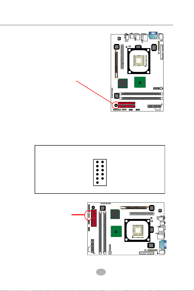
Chapter 2 Hardware Setup
RTL
PCI 1
DIMM1
FDC1
IDE1
IDE2
PW2
PW1 (Main Power)
B
I
O
S
DIMM2
DDR 400/333/266/200 MHz
AGP1 ( 8X/4X)
mPGA478B
VIA
VT6307S
Intel RG82845
i865G
Intel
BZ1
Battery
NJ1
SPK RST
PWLED
HDD
IR
PWR
1
2
+
-
+
-
LED
RTL
ALC850
AC'97
C
D
-
I
N
1
USB3
F
a
n
1
F
a
n
2
1
JFSB2
USB4
A
T
A
1
A
T
A
2
1
JFSB1
1
JBAT1
1
JKB1
W83627THF
Winbond
P
S
/
2
P
S
/
2
K
/
B
(
u
n
d
e
r
s
i
d
e
)
V
G
A
JPNT1
1
L
i
n
e
I
n
L
i
n
e
O
u
t
S
i
d
e
(
o
n
t
o
p
)
(u
n
d
e
r
s
id
e
)
(M
id
d
le
)
R
J
4
5
U
S
B
1
(
2
p
o
rts
)
(
o
n
t
o
p
)
V
C
O
M
1
(on top)
RT1
(
o
n
t
o
p
)
M
o
u
s
e
8110S
(+12V Power)
IC
H
5
R
In
te
l
1
1
U
S
B
2
(
2
p
o
r
ts
)
(
o
n
t
o
p
)
JAU
D1
1
1
2
R
e
a
r
S
p
e
a
k
e
r
C
e
n
te
r
/
S
u
b
w
o
o
fe
r
1
3
9
4
A
1
IEEE1
IC
H
5
o
r
A
G
2-10.8 System Buzzer: BZ1
A buzzer BZ1 is designed on board
for sending a beep at starting system as well as warning of CPU temperature problems.
RTL
ALC850
VT6307S
VIA
L
AC'97
AGP1 ( 8X/4X)
r
fe
/
r
o
e
n
O
i
t
u
o
te
n
(u
d
e
e
id
rs
)
w
n
b
e
u
C
L
n
i
e
I
n
e
d
S
i
S
d
id
(M
)
le
)
p
o
t
n
o
(
e
R
a
r
S
p
e
a
k
e
r
S
U
B
2
(2
1
N
I
-
D
C
1
1
n
1
a
F
JFSB1
JFSB2
PCI 1
V
2
/
S
P
1
M
O
C
V
e
s
u
o
1
3
9
4
A
J
R
)
p
o
t
n
o
(
n
o
(
o
)
p
rts
o
S
p
U
B
1
(2
RTL
8110S
mPGA478B
M
5
4
)
p
o
t
)
rts
(on top)
Winbond
W83627THF
)
p
o
t
n
o
(
1
K
B
/
P
S
2
/
RT1
)
e
e
d
d
r
s
n
i
(
u
1
JKB1
JPNT1
2
n
a
F
FDC1
System Buzzer BZ1
In
te
IC
H
o
r
IC
H
A
T
A
1
DIMM1
A
T
A
2
S
O
I
B
DIMM2
BZ1
HDD
LED
IR
PWR
2
JA
+
-
2
1
NJ1
1
+
-
SPK RST
PWLED
1
l
5
5
R
U
D
1
i865G
DDR 400/333/266/200 MHz
IDE2
IDE1
USB4
1
1
Intel
82845
Intel RG
USB3
Battery
PW1 (Main Power)
IEEE1
PW2
(+12V Power)
JBAT1
1
1
2-10.9 JAUD1: Front Panel Audio Connector
This series is designed with a Front Panel Audio connector “JAUD1.
• Supporting Front Panel S/PDIF Output, Front Panel Mic-In and Front
Panel Line-out;
• A S/PDIF cable is needed to connect this connector to Front Panel.
JAUD1: Audio-out Pin Assignment
Pin 1 SPDIF IN
Pin 3 GND
Pin 5 +5V
Pin 7 MIC IN
Pin 9 LINE OUT R
Pin11 LINE OUT L
Connect JAUDI
To Front Panel
11
1
2
12
Pin 2 Gnd
Pin 4 +5V
Pin 6 SPDIF OUT
Pin 8 +5VA
Pin10 GNDA
Pin12 KEY
35
Page 33
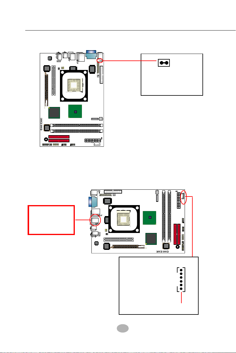
SL-B8E-FG / B8E-FGR
RTL
PCI 1
DIMM1
FDC1
IDE1
IDE2
PW2
PW1 (Main Power)
B
I
O
S
DIMM2
DDR 400/333/266/200 MHz
AGP1 ( 8X/4X)
mPGA478B
VIA
VT6307S
Intel R
G
82845
i865G
Intel
BZ1
Battery
NJ1
SPK RST
PWLED
HDD
IR
PWR
1
2
+
-
+
-
LED
RTL
ALC850
AC'97
C
D
-
I
N
1
USB3
F
a
n
1
F
a
n
2
1
JFSB2
USB4
A
T
A
1
A
T
A
2
1
JFSB1
1
JBAT1
1
JKB1
W83627THF
Winbond
P
S
/
2
P
S
/
2
K
/
B
(
u
n
d
e
r
s
i
d
e
)
V
G
A
JPNT1
1
L
i
n
e
I
n
L
i
n
e
O
u
t
S
i
d
e
(
o
n
t
o
p
)
(u
n
d
e
rs
id
e
)
(M
id
d
le
)
R
J
4
5
U
S
B
1
(2
p
o
rts
)
(
o
n
t
o
p
)
V
C
O
M
1
(on top)
RT1
(
o
n
t
o
p
)
M
o
u
s
e
8110S
(+12V Power)
IC
H
5
R
In
te
l
1
1
U
S
B
2
(2
p
o
rts
)
(
o
n
t
o
p
)
J
A
U
D
1
1
1
2
R
e
a
r
S
p
e
a
k
e
r
C
e
n
te
r/
S
u
b
w
o
o
fe
r
1
3
9
4
A
1
IEEE1
IC
H
5
o
r
2-10.10 RT1: Thermal Resistor
A
G
RTL
ALC850
VT6307S
VIA
n
i
L
(u
AC'97
AGP1 ( 8X/4X)
r
fe
r/
o
e
O
t
u
o
te
n
d
e
e
id
rs
)
w
n
b
e
u
C
i
L
n
I
e
n
e
d
S
i
(
S
d
id
(M
)
le
)
p
o
t
n
o
(
e
R
a
r
S
p
e
a
k
e
r
S
U
B
2
(2
1
N
I
-
D
C
1
1
1
a
F
n
JFSB1
JFSB2
PCI 1
V
2
/
S
P
1
M
O
C
V
e
s
u
o
1
3
9
4
A
J
R
)
p
o
t
n
o
n
o
(
o
)
p
rts
o
S
p
U
r
B
1
(2
RTL
8110S
mPGA478B
M
5
4
)
p
o
t
)
ts
(on top)
Winbond
W83627THF
)
p
o
t
n
o
(
1
K
B
/
P
S
2
/
RT1
)
i
e
d
r
s
e
d
n
(
u
1
JKB1
JPNT1
2
n
a
F
FDC1
RT1
RT1 is mounted with
Thermal Resistor by
default for detecting
system temperature.
l
5
r
5
R
JA
U
D
1
i865G
DDR 400/333/266/200 MHz
IDE2
IDE1
USB4
1
1
Intel
82845
Intel RG
USB3
Battery
PW1 (Main Power)
IEEE1
PW2
(+12V Power)
JBAT1
1
1
In
te
IC
H
o
IC
H
A
T
A
1
DIMM1
A
T
A
2
S
O
I
B
DIMM2
BZ1
HDD
LED
IR
PWR
2
+
-
2
1
NJ1
1
+
-
SPK RST
PWLED
1
2-10.11 1394A Front Connector : IEEE1
1394A Interface, with VT6307 Open Host Controller on board, supporting 2 x 1394A serial ports:
• Each 1394A port supporting 400/200/100 Mbits transfer rate.
1394A port
Connect 1394A
port directly to
1394A device.
• PCI-bus based open host
controller, compliant with IEEE
1394A-2000 standard for high
performance serial bus
IEEE1 Front Connector
Pin Assignment
Pin 1 BPWR(+12V)
Pin 2 GND
Pin 3 TPB(0/1/2)Pin 4 TPB(0/1/2)+
Pin 5 TPA (0/1/2)Pin 6 TPA (0/1/2)+
Connect to Front Panel
with IEEE cable
36
1
6
Page 34
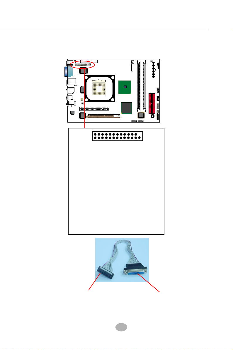
Chapter 2 Hardware Setup
RTL
PCI 1
DIMM1
FDC1
IDE1
IDE2
PW2
PW1 (Main Power)
B
I
O
S
DIMM2
DDR 400/333/266/200 MHz
AGP1 ( 8X/4X)
mPGA478B
VIA
VT6307S
Intel R
G
82845
i865G
Intel
BZ1
Battery
NJ1
SPK RST
PWLED
HDD
IR
PWR
1
2
+
-
+
-
LED
RTL
ALC850
AC'97
C
D
-
I
N
1
USB3
F
a
n
1
F
a
n
2
1
JFSB2
USB4
A
T
A
1
A
T
A
2
1
JFSB1
1
JBAT1
1
JKB1
W83627THF
Winbond
P
S
/
2
P
S
/
2
K
/
B
(
u
n
d
e
r
s
i
d
e
)
V
G
A
JPNT1
1
L
i
n
e
I
n
L
i
n
e
O
u
t
S
i
d
e
(
o
n
t
o
p
)
(u
n
d
e
rs
id
e
)
(M
id
d
le
)
R
J
4
5
U
S
B
1
(2
p
o
rts
)
(
o
n
t
o
p
)
V
C
O
M
1
(on top)
RT1
(
o
n
t
o
p
)
M
o
u
s
e
8110S
(+12V Power)
IC
H
5
R
In
te
l
1
1
U
S
B
2
(2
p
o
rts
)
(
o
n
t
o
p
)
JA
U
D
1
1
1
2
R
e
a
r
S
p
e
a
k
e
r
C
e
n
te
r/
S
u
b
w
o
o
fe
r
1
3
9
4
A
1
IEEE1
IC
H
5
o
r
2-10.12 Printer Port: JPNT1 (optional)
JPNT1 is an optional parallel printer port.
14
113
26
JPNT1: Printer Port (optional)
Pin Assignment
Pin 1 STROBE#
Pin 2 LPTDD0
Pin 3 LPTDD1
Pin 4 LPTDD2
Pin 5 LPTDD3
Pin 6 LPTDD4
Pin 7 LPTDD5
Pin 8 LPTDD6
Pin 9 LPTDD7
Pin 10 ACK#
Pin 11 BUSY
Pin 12 PE
Pin 13 SLCT
To Printer Connector
on board
Printer Cable (optional)
Pin 14 AUTOFD#
Pin 15 ERROR#
Pin 16 INITA#
Pin 17 SLCTIN#
Pin 18 GND
Pin 19 GND
Pin 20 GND
Pin 21 GND
Pin 22 GND
Pin 23 GND
Pin 24 GND
Pin 25 GND
Pin 26 Key
To Printer
37
Page 35

SL-B8E-FG/B8E-FGR
Chapter 3 Software Setup
Drivers, Utilities and Software Installation
• Support CD:
This series of mainboards will be shipped with a Support CD which
contains those necessary driver files, Application Softwares and some
helpful utilities. It is a user-friendly, auto-run CD which will open itself
up in a CD-ROM automatically.
This chapter is devoted to describing the installations of all these essential drivers and utilities on Windows 9X, Windows ME, Windows
2000 and Windows XP. And installation on Windows XP as the general
illustration hereby.
The priority of drivers to be installed should also be noted. Users are
recommended to take the following installation orders :
3-1 To Open up the Support CD ................................................ 41
3-2 Intel Chipset Software Installation Utility........................ 42
3-3 Graphics Driver Installation ............................................... 43
3-4 AC’97 Audio Driver Installation......................................... 44
3-4.1 Installing AC’97 6-channel Audio Driver ............................... 44
3-4.2 Verifying 6-channel Audio ........................................................45
3-5 To Install RTL8110S Gigabit Ethernet Drivers ............... 47
3-6 IAA RAID Driver (for Win2000/XP only) ......................... 48
3-7 To Install Hardware Monitor Utility.................................. 49
3-7.1 Installation ................................................................................... 49
3-7.2 Verification .................................................................................. 50
3-8 To Install USB 2.0 Driver for Windows 2000/XP ............. 51
38
Page 36
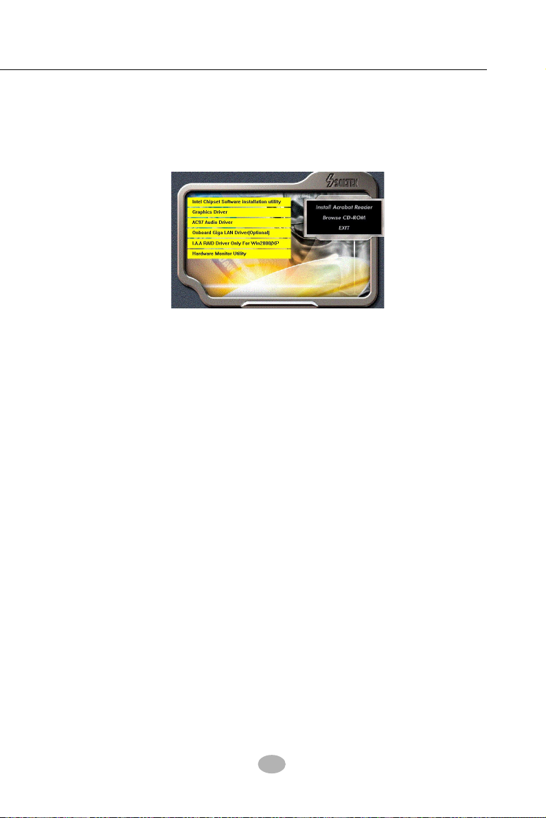
Chapter 3 Software Setup
3-1 To Open up the Support CD
1. Please put the Support CD enclosed in your mainboard package into
the CD-ROM drive. In a few seconds, the Main Menu will automatically appear, displaying the contents to be installed for this series:
2. In case your system does not open the Support CD automatically,
please click to the following path to enter the Main Installation Menu:
D:\ Autorun.exe (assuming that your CD-ROM Drive is Drive D)
3. Drivers may be updated from time to time in our web site. If you are
installing a newer driver than the one illustrated in this chapter, please
be aware that the illustration pictures might be different.
39
Page 37
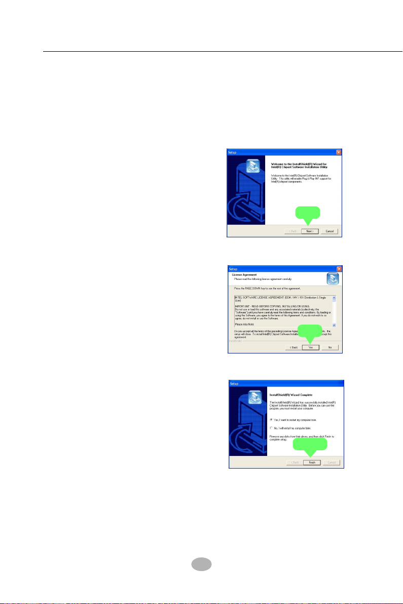
SL-B8E-FG/B8E-FGR
3-2 Intel Chipset Software Installation Utility
1. Following the procedures of opening the Support CD, click to “
Install Intel Chipset software installation Utility” to proceed.
2. The Intel Service Pack
InstallShield Wizard will pop
up to guide you to the Intel
Service pack installation.
Press “Next” button to
continue.
Next
3. “Intel Software License
Agreement” screen will
appear, please click the
“Yes” button to agree with
the Licence Agreement and
continue.
Yes
4. After all the setup process
is finished, please restart
your computer by clicking
on “Finish” so as to take
the Utility into effect.
Finish
40
Page 38
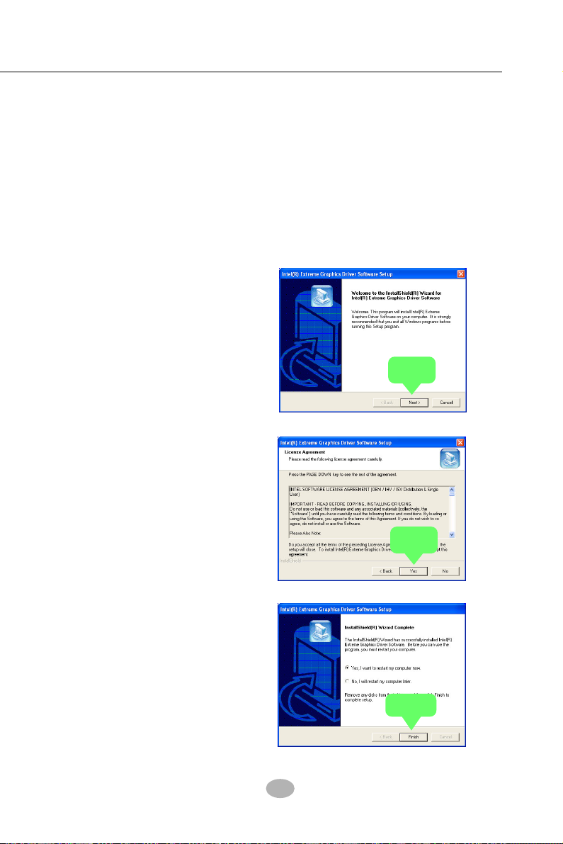
Chapter 3 Software Setup
3-3 Graphics Driver Installation
When restarting procedures finish, please open the Support CD with
your CD-ROM to enter the Main Installation Menu.
1. For installation of on-board VGA driver, you must first connect the
monitor to the on-board VGA connector. Then click to “Install Graphics
Driver”. The Graphics Driver is specifically for on-board VGA.
2. When the screen of “Intel(R)
Extreme Graphics Driver
Software Setup” appears,
please press “Next” button to
continue.
Next
3.On the “Licence Agreement”
screen, click on “Yes” to
continue.
4. After all the setup procedures
have completed, click to
“Finish” button to exit the
Installation program and restart your system.
Yes
Finish
41
Page 39

SL-B8E-FG/B8E-FGR
3-4 AC’97 Audio Driver Installation
RTL ALC850 8-channel AC97 Audio Codec on board, AC’97 2.3 compatible stereo audio code for PC multimedia systems. AC’97 Audio Codec Driver
is provided in Support CD for user’s installation.
3-4.1 Installing AC’97 6-channel Audio Driver
1. Following the procedures of opening the Support CD, click to “ AC’97
Audio Driver” to proceed.
2. Instantly, the “installShield
Wizard” screen appears to
guide you through the “AC’97
Audio Setup””.
Next
3. instantly, the Setup program
proceeds to install the
softwares. (If you want to stop
setup, click the “Cancel”
button.)
4. After the setup process is
finished, please check the radial
button “Yes, I want to restart my
computer now.” And click
“Finish” to restart your system.
Finish
42
Page 40
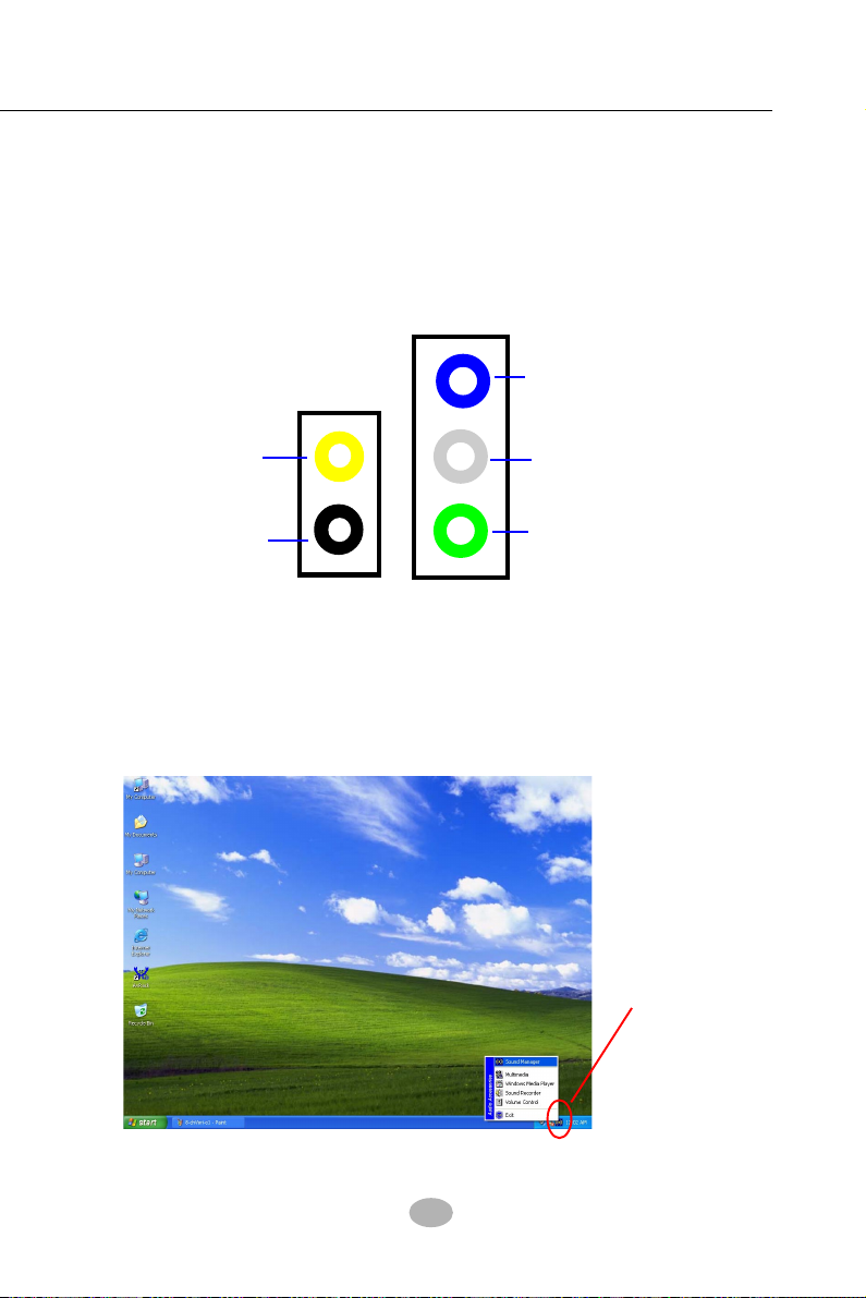
Chapter 3 Software Setup
3-4.2 Verifying 6-channel Audio
After installation of AC’97 6-channel Codec, you must configure the 5.1
Speaker connection to enable the 8-channel audio.
1. Connect your on-board Audio Connector to your 8-channel speakers
as depicted in the figure below:
Line In
Pink Connector
Center/ Subwoofer
Speaker Out
Black Connector
To Rear Speaker Out
Gray Connector
to Side Speaker
Light Green Connector
to Front Speaker
Back Panel Audio Connectors
2. After Connection is done, start your Windows system and double
click the Sound manager icon to enter 8-channel configuration:
Sound Effect
Manager icon on
Windows XP
43
Page 41

SL-B8E-FG/B8E-FGR
3. The AC’97 Audio Configuration” screen will pop out. Clikc the “Speaker
Configuration” bar with your mouse.
4. Instantly, the “Speaker Configuration” screen will pop out. Pick the
items “8-channelSpeaker” and then click on the Auto Test button.
Instantly, the Speaker Auto-test starts until all speakers installed are
tested.
44
Page 42

Chapter 3 Software Setup
3-5 To Install RTL8110S Gigabit Ethernet Drivers
RTL8110S Gigabit LAN driver for Windows 98/ME / 2000 / XP. After
restarting system, click on the Onboard Giga LAN Driver to start setup.
1. Instantly, the InstallShield Wizard
pop out. Click Next to continue.
2. Next, the program starts to copy
files.
3. In a few seconds, setup completes.
Restart system and complete
setup.
45
Page 43

SL-B8E-FG/B8E-FGR
3-6 IAA RAID Driver (for Win2000/XP only)
Click on the IAA RAID Driver Only for Win2000/XP to start setup.
2. Instantly, the InstallShield
Wizard pops out to start
setup.
2. Click Yes to the License
Agreement and continue.
3. The program is copying
files.
Next
Yes
4. In a few seconds, setup
completes.
Click “Finish” to restart
system and complete
setup.
Finish
46
Page 44

Chapter 3 Software Setup
3-7 To Install Hardware Monitor Utility
3-7.1 Installation
Hardware Monitor is built on this mainboard. Its installation is pro-
grammed to a fully automated mode on Windows 9X/Me/NT4/2000/
XP. Users can follow the model installation below for its installation
on various Windows System.
1.Following the procedures of opening the Support CD, click to “
Hardware Monitor Utility” to proceed.
2. The Soltek Hardware
Monitor InstallShield
Wizard will pop up to guide
you to the Intel Service pack
installation. Press “Next”
button to continue.
3. The InstallShield Wizard
screen will show the current
setting, please click the
“Install” button to continue.
Next
4. After all the setup process
is finished, click “Finish” to
exit the wizard.
Install
Finish
47
Page 45

SL-B8E-FG/B8E-FGR
3-7.2 Verification
1. After installing Soltek Hardware
Monitor, double click “SoltekHM”
icon on the desktop to open the main
window of the Soltek Hardware
Doctor.
2.Then the pop-up screen will show all information about CPU
Temperature, Fan Speed and various Voltages.
Showing the Fan Speed(s) that
Showing the temperature(s), the
function of which is supported by
the mainboard.
is supported by the mainboard.
Click on “Soltek” button to
display the function menu.
Showing the Voltage(s) that is
supported by the mainboard.
Status Warning LED
*Note: Not all items or functions showing in the above picture will
show up. Only those items or functions that are supported
by the mainboard will reveal themselves in the above
screen.
48
Page 46

Chapter 3 Software Setup
3-8 To Install USB 2.0 Driver for Windows 2000/XP
USB V2.0 with its 480Mb/s transfer rate supports operating system
Windows 2000 and Windows XP via the Windows 2000 and Windows
XP Service Pack.
install the latest Service Pack for Windows 2000 or Windows XP. (Intel
USB 2.0 does not support Windows 9X/Me)
1. After installation of Intel Chipset software installation Utility in Windows
2000 or Windows XP, start to install the latest Service Pack version
into the operating system. The installation of the latest Service Pack
will support USB2.0 in Windows 2000 or Windows XP now.(The latest
Service Pack can be found in Microsoft Web Site.)
2. To verify USB2.0 installation, please enter “Device Manager” of “My
Computer”. On the “Device Manager” screen, you should be able to
see the item “Standard Enhanced PCI to USB Host Controller”,
verifying USB2.0 Driver is installed successfully.
For achieving Intel USB 2.0 support, users should
49
Page 47

SL-B8E-FG / B8E-FGR
Chapter 5 SATA RAID Setup
ICH5R RAID Controller & RAID Driver
Intel ICH5R RAID (Redundant Array of Independent Disks) Controller
is built in the South BridgeICH5R. With this RAID Controller, the
IntelSATA RAID BIOS is built into the system to help configure the
Redundant Disk Array. ICH5R supports RAID 0 and RAID 1
configuration.
This Chapter is to introduce the SATA RAID Configurations :
5-0 About Disk Array................................................................... 84
5-0-1 Disk Array Interpretation.......................................................... 84
5-0-2 Disk Array Member .................................................................... 84
5-0-3 Disk Array Types Supported by ICH5R .................................84
5-1 Enable SATA RAID in System BIOS ................................. 85
5-2 To Enter Intel RAID BIOS Utility Setup........................... 86
5-3 To Create Disk Array ............................................................ 87
5-4 To Install SATA RAID Driver .............................................. 90
5-4-1 To Install SATA RAID Driver on Windows 2000/XP............ 90
5-4-2 To run Windows 98SE/ME without ICH5R RAID driver .. 93
78
Page 48

Chapter 5 ICH5R SATA RAID
5-0 About Disk Array
5-0-1 Disk Array Interpretation
A “Disk Array” is formed from a group of 2 or more disk drives with the
RAID (Redundent Array of Independent Disks) technology. The aim of
a Disk Array is to provide better perfornance and/or data fault tolerance.
5-0-2 Disk Array Member
The individual disk drive in an array is called a “member”. Each member
of a specific disk array is coded in their “reserved sector” with
configuration information that identifies the drive as a member. All disk
members in a formed disk array are recognized as a single physical
drive to the system.
5-0-3 Disk Array Types Supported by ICH5R
Different types or modes of Disk Array have different formation models
and functions.
types of Disk Arrays: RAID 0 and RAID 1, but not RAID 0+1.
1. RAID 0 (or Striping mode):
RAID 0 is a group of 2 to 4 Disk Drives configured together with
RAID technology to provide better data transfer performance than a
single drive since the workload is balanced between the array
members. Reads and Writes of RAID 0 data are interleaved between
multiple drives. When any disk member fails, it affects the entire array.
The disk array size is equal to the number of drive members times
the smallest member capacity. For example, one 1GB and three 1.
2GB drives will form a 4GB (4x1GB) disk array.
2. RAID 1 (or Mirroring mode):
RAID 1 is a group of 2 Disk Drives configured together with RAID
Technology to provide the fault tolerance function. Writes duplicate
data on to RAID 1 while reads are performed in parallel. If one of the
mirrored drives suffers a mechanical failure (e.g. spindle failure) or
does not respond , the remaining drive will continue to function. This
is called Fault Tolerance.
The drive capacity of RAID 1 is half the total drive capacity of two
equal-size drive.
The South Bridge on this mainboard supports only two
79
Page 49
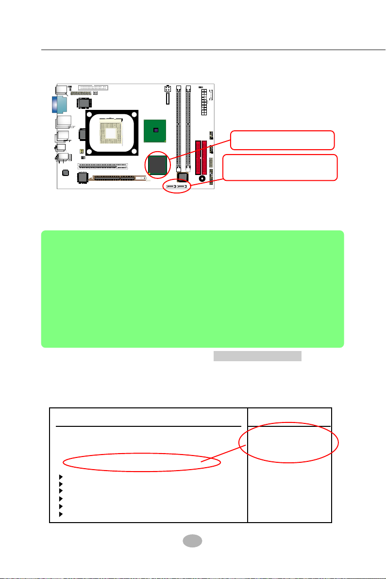
SL-B8E-FG / B8E-FGR
RTL
PCI 1
DIMM1
FDC1
IDE1
IDE2
PW2
PW1 (Main Power)
B
I
O
S
DIMM2
DDR 400/333/266/200 MHz
AGP1 ( 8X/4X)
mPGA478B
VIA
VT6307S
Intel R
G
82845
i865G
Intel
BZ1
Battery
NJ1
SPK RST
PWLED
HDD
IR
PWR
1
2
+
-
+
-
LED
RTL
ALC850
AC'97
C
D
-
I
N
1
USB3
F
a
n
1
F
a
n
2
1
JFSB2
USB4
A
T
A
1
A
T
A
2
1
JFSB1
1
JBAT1
1
JKB1
W83627THF
Winbond
P
S
/
2
P
S
/
2
K
/
B
(
u
n
d
e
r
s
i
d
e
)
V
G
A
JPNT1
1
L
i
n
e
I
n
L
i
n
e
O
u
t
S
i
d
e
(
o
n
t
o
p
)
(u
n
d
e
rs
id
e
)
(M
id
d
le
)
R
J
4
5
U
S
B
1
(2
p
o
rts
)
(
o
n
t
o
p
)
V
C
O
M
1
(on top)
RT1
(
o
n
t
o
p
)
M
o
u
s
e
8110S
(+12V Power)
IC
H
5
R
In
te
l
1
1
U
S
B
2
(2
p
o
rts
)
(
o
n
t
o
p
)
J
A
U
D
1
1
1
2
R
e
a
r
S
p
e
a
k
e
r
C
e
n
te
r/
S
u
b
w
o
o
fe
r
1
3
9
4
A
1
IEEE1
IC
H
5
o
r
5-1 Enable SATA RAID in System BIOS
Chipset ICH5R supporting
SATA RAID Interfaces.
2 SATA connectors supporting
2 SATAHard Disks for RAID
mode.
To enable SATA RAID controller, boot the system and watch for the
following initial screen to appear:
Inrel RAID for Serial ATA-RAID BIOS vxxxxxxx
Copyright (C) 2003 Intel Corporation. All right reserved.
RAID Volumes:
None defined.
Non-RAID Disks:
Port Drive Model Serial # Size Status Bootable
0 ST380023AS XXXXXXXXX 115.0GM Normal Yes
1 Maxtor 6Y120M0 XXXXXXXXX 114.0GM Normal Yes
Press <CTRL-I to enter Configuration Utility..
(The above message indicates that the SATA hard disks on board are detected by the
RAID BIOS.)
As soon as the above screen appears, press < Delete > key
(not <CTRL-I> key) to enter CMOS BIOS Setup. Choose “Advanced
(not <CTRL-I> key)
BIOS Features” and “IDE Configuration” to configure S-ATA as RAID.
IDE Configuration
IDE Configuration
IDE Configuration P/S-ATA (Auto)
S-ATA Running Enhanced Mode Yes
P-ATA Channel Selection Both
S-ATA Ports Definition P0-3rd./P1-4th
Configure S-ATA as RAID Yes
Primary IDE Master Hard Disk
Primary IDE Slave ATAPI CDROM
Secondary IDE Master Not Detected
Secondary IDE Slave Not Detected
Third IDE Master Not Detected
Fourth IDE Master Not Detected
80
Help Item
Choose “yes” to enable
SATA RAID configuration.
Page 50
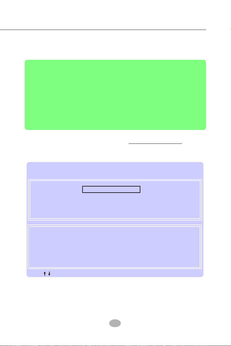
Chapter 5 ICH5R SATA RAID
5-2 To Enter Intel RAID BIOS Utility Setup
Boot the system with “SATA-RAID ” enabled in system BIOS Setup and
watch for the following initial screen to appear:
Inrel RAID for Serial ATA-RAID BIOS vxxxxxxx
Copyright (C) 2003 Intel Corporation. All right reserved.
RAID Volumes:
None defined.
Non-RAID Disks:
Port Drive Model Serial # Size Status Bootable
0 ST380023AS XXXXXXXXX 115.0GM Normal Yes
1 Maxtor 6Y120M0 XXXXXXXXX 114.0GM Normal Yes
Press <CTRL-I to enter Configuration Utility..
(The above message indicates that the SATA hard disks on board are detected by the
RAID BIOS.)
As soon as the above screen appears,
press < CTRL-I > key to enter
Intel RAID Configuration Utility.
In a few seconds, the Intel RAID Setup Utility appears as shown below:
Intel(R) for Serial ATA-RAID Configuration Utility
Copyright 2003 Intel Corporation. All Right Reserved. vxxxxxxxxx
[ MAIN MENU ]
1. Create RAID Volume
2. Delete RAID Volume
3. Reset Disks to Non-RAID
4. Exit
[ Disk/Volume Information ]
RAID Volumes:
None Defined.
Non-RAID Disks:
Port Drive Model Serial # Size Status Bootable
0 ST380023AS XXXXXXXXX 115.0GM Normal Yes
1 Maxtor 6Y120M0 XXXXXXXXX 114.0GM Normal Yes
[ ]-Select [ESC] - Exit [Enter] - Select Menu
81
Page 51
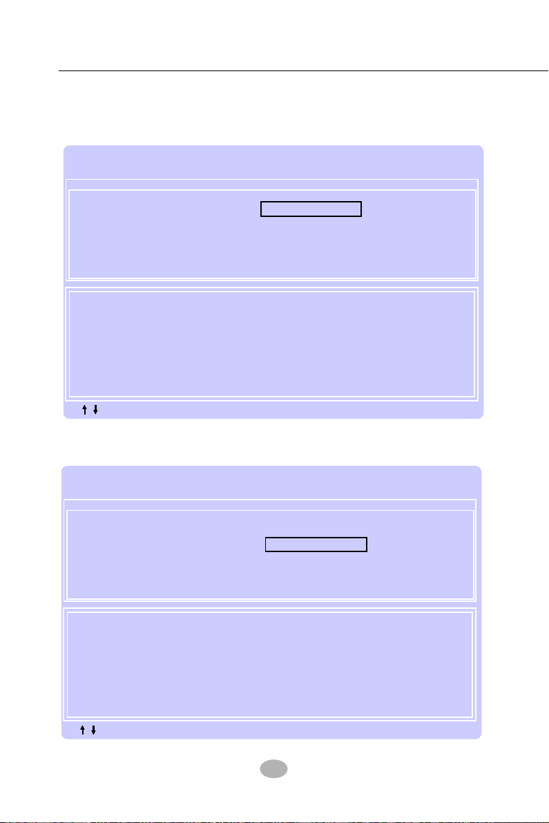
SL-B8E-FG / B8E-FGR
5-3 To Create Disk Array
(5-3-1) When you press <Enter> on the “1. Create RAID Volume” bar,
the following screen shows up. Enter a name for the volume to be
created.
Intel(R) for Serial ATA-RAID Configuration Utility
Copyright 2003 Intel Corporation. All Right Reserved. vxxxxxxxxx
[ Create Array MENU ]
Name: RAID Volume 1
RAID Level: RAID1(Mirror)
Strip Size: 128KB
Capacity: 228.9GB
Create Volume
[ Help ]
Enter a string between 1 and 16 characters in length that can be used
to uniquely identify the RAID volume. This name is case sensitive and
cannot contain special characters.
[ ]-Change [Tab] - Next [ESC] - Previous Menu [Enter] - Select Menu
(5-3-2) Next, press <Tab> key to jump to RAID Level bar and press
Arrow key to select the RAID mode.
Intel(R) for Serial ATA-RAID Configuration Utility
Copyright 2003 Intel Corporation. All Right Reserved. vxxxxxxxxx
[ Create Array MENU ]
Name: RAID Volume 1
RAID Level: RAID1(Mirror)
Strip Size: 128KB
Capacity: 228.9GB
Create Volume
[ Help ]
Choose the RAID level best suited to your usage model.
RAID0(Stripe) - Create a volume where equal portions of the volume
RAID1(Mirror)) - Create a volume where a redundant copy of the data is
[ ]-Change [Tab] - Next [ESC] - Previous Menu [Enter] - Select Menu
are spread accross all the disks. This creates a volume
with higher performance by accessing all disks at once.
stored on each disk. This creates a volume protected
from a single hard disk failure.
82
Page 52
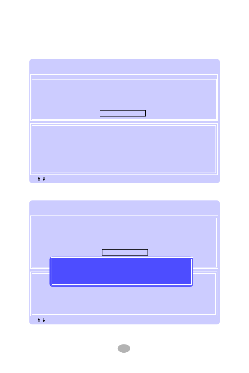
Chapter 5 ICH5R SATA RAID
(5-3-3) After selecting the RAID mode, press <Enter> to confirm your
choice. Then press <Enter> again on the Create Volume bar to proceed.
Intel(R) for Serial ATA-RAID Configuration Utility
Copyright 2003 Intel Corporation. All Right Reserved. vxxxxxxxxx
[ Create Array MENU ]
Name: RAID Volume 1
RAID Level: RAID1(Mirror)
Strip Size: 128KB
Capacity: 228.9GB
Create Volume
[ Help ]
Press “Enter” to Create the Specified volume.
[ ]-Change [Tab] - Next [ESC] - Previous Menu [Enter] - Select Menu
(5-3-4) Press <Y> on the following screen to proceed.
Intel(R) for Serial ATA-RAID Configuration Utility
Copyright 2003 Intel Corporation. All Right Reserved. vxxxxxxxxx
[ Create Array MENU ]
Name: RAID Volume 1
RAID Level: RAID1(Mirror)
Strip Size: 128KB
Capacity: 228.9GB
Create Volume
Are you sure you want to create this volume? (Y/N):
Press “Enter” to Create the Specified volume.
[ ]-Change [Tab] - Next [ESC] - Previous Menu [Enter] - Select Menu
[ Help ]
83
Page 53

SL-B8E-FG / B8E-FGR
(5-3-5) Instantly, the RAID 1 mode is set up and shown on the screen.
Then press <Esc> key to exit the screen.
Intel(R) for Serial ATA-RAID Configuration Utility
Copyright 2003 Intel Corporation. All Right Reserved. vxxxxxxxxx
[ MAIN MENU ]
1. Create RAID Volume
2. Delete RAID Volume
3. Reset Disks to Non-RAID
4. Exit
[ Disk/Volume Information ]
RAID Volumes:
ID Name Level Strip Size Status Bootable
0 RAID_Volume1 RAID1(Mirror) N/A 114.4GB Normal Yes
ST380023AS XXXXXXXXX Port0 114.4GB Normal
Maxtor 6Y120M0 XXXXXXXXX Port1 115.0GM Normal
[ ]-Select [ESC] - Exit [Enter] - Select Menu
(5-3-6) On the next screen, enter Y to confirm exit.
Intel(R) for Serial ATA-RAID Configuration Utility
Copyright 2003 Intel Corporation. All Right Reserved. vxxxxxxxxx
[ MAIN MENU ]
1. Create RAID Volume
2. Delete RAID Volume
3. Reset Disks to Non-RAID
4. Exit
[ Confirm Exit ]
Are you sure you want to exit? (Y/N):
[ Help ]
[ Disk/Volume Information ]
RAID Volumes:
ID Name Level Strip Size Status Bootable
0 RAID_Volume1 RAID1(Mirror) N/A 114.4GB Normal Yes
ST380023AS XXXXXXXXX Port0 114.4GB Normal
Maxtor 6Y120M0 XXXXXXXXX Port1 115.0GM Normal
[ ]-Select [ESC] - Exit [Enter] - Select Menu
84
Page 54

Chapter 5 ICH5R SATA RAID
5-4 To Install SATA RAID Driver
SATA-RAID Driver is incorporated in Support CD/Floppy Diskette for
user’s installation.
Since Intel has not yet provided RAID driver for Win98, ICHR RAID
system run with Win98 is not recommended
5-4-1 To Install SATA RAID Driver on Windows 2000/XP
(1) Get ready the Floppy Diskette holding the RAID Driver.
(This Driver Diskette should have been enclosed in the mainboard
Package.)
(2) Check that SATA Hard Disks are connected properly to the SATA
Connectors.
(3) Start your PC system and use RAID BIOS Setup Utility to configure
RAID 0 or RAID 1 to the hard disks. (For SATA Interface, skip the
RAID configuration.)
(4) Restart System and format the bootable hard disks.
(5) Now, apply the Windows 2000/XP CD to CD-ROM for operating
system installation.
(6) On the Windows 2000 Setup screen, press “F6” key to set up RAID
driver for Windows 2000/XP.
Windows Setup
This driver is intended forWinXP/2K only.
Press F6 if you need to install a third party SCSI or RAID driver....
(7) On next screen when you are instructed to insert the RAID Driver
Diskette into Floppy drive, follow the instruction to continue and
complete the installation.
85
Page 55

SL-B8E-FG / B8E-FGR
(7) On next screen press “S” to confirm the mass storage device setup.
Windows Setup
Setup could not determine the type of one or more mass storage
devices installed in your system, or you have chosen to manually
specify an adapter. Currently, Setup will load support for the
following mass storage devices(s):
<none>
* To specify additional SCSI adapters, CD-ROM drives, or
special disk controllers for use with Windows, including
those for which you have a device support disk from a
mass storage device manufacturer, press S.
* If you do not have any device support disks from a mass
storage device manufacturer, or do not want to specify
additional mass storage devices for use with Windows,
press ENTER.
S=Specify Additional Device Enter=Continue F3=Exit
(8) On next screen apearing, insert the RAID Driver Diskette to Drive
“A” and then press <Enter>.
Windows Setup
Please insert the disk labeled
Manufacturer-supplied hardware support disk
into Drive A:
* Press ENTER when ready.
Enter=Continue ESC=Cancel F3=Exit
86
Page 56

Chapter 5 ICH5R SATA RAID
(9) On the next screen, you are prompted to install the “Intel(R)
82801ER Controller” driver.
So, press <Enter> on to continue.
Windows Setup
You have chosen to configure a SCSI Adapter for use with Windows,
using a device support disk provided by an adapter manufacturer.
Select the SCSI Adapter you want from the following list, or press
ESC to return to the previous screen.
Intel(R) 82801ER SATA RAID Controller
Enter=Select F3=Exit
(10) Next screen will show that you have chosen the RAID device driver
to set up. Press Enter to continue, and the Installation Program will
then guide you through the rest of system setup.
Windows Setup
Setup will load support for the following mass storage driver(s):
Intel(R) 82801ER SATA RAID Controller
* To specify additional SCSI adapters, CD-ROM drives, or
special disk controllers for use with Windows, including
those for which you have a device support disk from a
mass storage device manufacturer, press S.
* If you do not have any device support disks from a mass
storage device manufacturer, or do not want to specify
additional mass storage devices for use with Windows,
press ENTER.
S=Specify Additional Device Enter=Continue F3=Exit
(11) When the system is completely installed, the RAID driver will also
be installed into the system.
87
Page 57
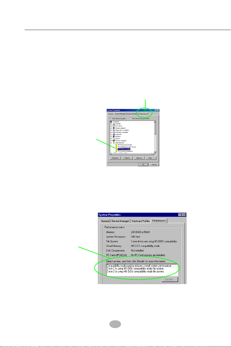
SL-B8E-FG / B8E-FGR
5-4-2 To run Windows 98SE/ME without ICH5R RAID driver
(1) You may also install Win98/Me on ICH5R RAID system, but there is
no ICH5R RAID driver to support Win98/Me.
(2) In the Win98 system run with RAID configuration, take the following
path to check the system performance:
My Computer/Propertie/Device manager
Click on Performance
The question mark here
indicates that RAID
Controller Driver
is not installed yet.
(3) Instantly, the “Performance “ page shows up, stating that
Compatibility mode reduces overall system performance.
Win98/Me run in ICH5R RAID configuration is not recommended.
The system
performance is
reduced.
88
 Loading...