


PINE RIDGE IV PLAY SYSTEM
lynwood
Bayside
Pine Ridge 3
17½ ft
10 ft
12ft
20'- 6"
8' 0"
20' 6"
3403230
F23230
Effective June 26/09
ASSEMBLY INSTRUCTIONS
Play System dimension with
safety allowance: 32’6” x 20’
8-10 Hrs
Prior to assembly, you MUST read the Owner’s Manual for important safety warnings and details on installing a shock absorbing surface.
This unit’s maximum fall height is 7.5 feet and is intended for a maximum of 7 users, ages 3 to 10 (110 lbs. per child).
For questions, assembly help or assistance with missing or defective parts:
North America
Solowave Design
375 Sligo Rd. West PO Box 10
Mount Forest, Ontario Canada
N0G 2L1
General Inquiries:
Toll Free: 1-877-966-3738
Email: support@solowavedesign.com
United Kingdom
General Inquiries:
Toll Free: 0870 145 2145
Email: info@selwoodproducts.co.uk
Other Countries:
Please refer to label affixed to outside of carton.
The 1-877 number on the Owners Manual &
Safety Instructions is for North America only.

Important Information: Please ensure page is read.
2
ABOUT OUR WOOD
Solowave Design™ uses only Premium playground lumber, ensuring the safest product for your children’s
use. Although great care has been taken in selecting the best quality lumber available, wood is a product
of nature and susceptible to weathering (changes in the aesthetics of the wood). A light sanding may be
required to remove minor splinters. For your information, we have described some changes that may occur
as a result of weathering:
1. Checking Checks are surface cracks in the wood along the grain. 4” x 4” material will
experience more checking than 2”, 1-1/4” or 1” material be cause the surface
and interior moisture content will vary more widely than in thinner wood.
2. Warping Warping refers to any distortion (twisting, cupping) from the true plane that
may take place during weathering.
3. Fading Wood exposed to sunlight, will over time, turn a grey color.
Note: The above changes will not affect the strength of the product.
Due to changes in the climate
What causes weathering?
One of the main reasons for weathering is the
effects of water (moisture); the moisture content
of the wood at the surface is different than the
interior of the wood. As the moisture moves in
or out of the wood (result of climate changes),
the different moisture content causes tension
in the wood, which can result in checking and
or warping.
moisture moves in and out
of the wood
Moisture content will vary
throughout any piece of wood.
How can I reduce the amount of weathering to my Play System?
At the factory we have added water repellent to the stain. This water repellent decreases the amount of water
absorption during rain or snow thus decreasing the tension in the wood. Sunlight will break down the water
repellent, so we recommend applying a water repellent on a yearly basis (see your local stain and paint supplier
for a recommended product). Also if storing the product before installation, make sure you store out of direct
sunlight in a cool dry place.
Will weathering affect the strength of my Play System?
Most weathering is just the normal result of nature and will not affect safe play and enjoyment for your child.
However if you are concerned that a part has experienced a severe weathering problem please call our
consumer relations department for further assistance.
© Solowave Design. All rights reserved.

HELPFUL HINTS
Tools Required
Important Information: Please ensure page is read.
Shovel
Measuring
Tape
Drill (1/8”
3/16” Bit)
Safety
Glasses
Hammer Ratchet 1/2”,
Swing Hangers
Swing hangers must be screwed into the wood
the full length of the shaft, so that the triangular
head is touching the wood (see swing hanger
diagram). Failure to correctly install swing hangers
may result in the hanger itself breaking, or the
hanger becoming dislodged from the wood.
Either circumstance can cause serious injury. Big
Backyard cannot assume any responsibility for
incorrect installation of swing hangers.
(Liquid soap may be used as a lubricant for ease
of installation).
NOTE: Follow proper assembly procedure.
Swing BeamSwing Beam
Swing Hanger orientation for
swing attachment.
Screw Hanger in until
it is snug and flush with
bottom of Swing Beam.
Swing HangerSwing Hanger
7/16” & 9/16”
Level #2 & #3 Phillips
or Robertson
Square
Ruler
Tee - Nuts & Lock washers
Place tee-nut in hole and tap into place with
hammer. Insert the hex bolt through, first the
lock washer and then the flat washer, and feed
through hole. Hand tighten to ensure bolt and
tee-nut connection (this may not be possible due
to coating on hardware, if not use a ratchet), and
then proceed with ratchet. DO NOT over tighten.
Hardware should not crush wood.
NOTE: A 1/4” lock washer and flat washer, are used with
1/4” hex bolt or 5/16” with 5/16”.
Hex Bolt
Lock Washer
Flat Washer
Tee-Nut
Wood
Dowel Installation
Step
Ladder
Warning: For your child’s safety orientate the swing
hangers as shown to ensure your swing will have the proper
swinging motion when installed. Failure to do so could result in
the premature breaking off of the swing hanger or swing chain.
Hardware
When making the selection of 1/4” and 5/16”
hardware, carefully read the instructions in each
step of this manual to ensure the proper hardware
is used.
NOTE: 5/16” Hardware is larger in diameter than 1/4”.
The Swing Triangle Plate has a total of 5 holes,
and they are all used depending on where you are
installing it. When installing the plates, pay close
attention to the holes required. When complete,
the swing end should be angled out (away from
fort) approx. 110˚
NOTE: In the event that the thread of a Hex Bolt is
exposed beyond the tee-nut, please disassemble, add
another flat washer to head of hex bolt and reassemble.
© Solowave Design. All rights reserved.
1. Insert Dowel into provided holes until the
shoulder of tenon is flush to the face of the
Swing Rail or Access Rail or
Ladder Post.
2. Pre-drill a 3 x 1/8” hole through Rail or Post
prior to securing with wood screw. Securing with
screw prior to pre-drilling may lead to cracking
and must be avoided.
3. Secure dowel in place with approprate wood
screws and instructed within manual.
1/8” Drill Bit
Shoulder
Dowel
Tenon
Rail

Wood Identification
4
(Reduced Size Parts)
Before you assemble your fort, please identify and count your boards.
Remember, wood is a product of nature and affected by changes in
weather. Although the wood in this set has been carefully selected, expansion
and contraction may cause slight warping, twisting or
checking of the boards while in the carton. This is a natural
characteristic of wood and
will not
affect the structural integrity of
your set.
Profile dimensions denoted in these instructions are based on wood size before
machining and finishing. Actual size will be smaller.
Nominal
Size
2" x 6"
2" x 4
"
2" x 3"
2" x 2"
5/4
" x 4"
1" x 5"
1" x 6"
Actual
Size
1 3/8" x 5 3/8"
1 3/8" x 3 3/8"
1 3/8" x 2 3/8"
1 1/2" x 1 1/2"
1" x 3 1/2"
5/8" x 4 1/2"
5/8" x 5 3/8"
3660729
(1) Roof Mount (2 x 3 x 23")
(1) SW Roof Mount (2 x 4 x 59-1/4")
3660731
(2) Ground Side (1 x 5 x 56")
(1) Ground Front (1 x 5 x 59-1/4")
(1) Floor Front (2 x 3 x 58-1/4")
(1) Front Top (1 x 4 x 58-1/4")
3660702
3660721
(1) Rope Bottom (1 x 6 x 59-1/4")
3660752
3660730
3660711
(2) Roof Side (1 x 4 x 47-3/4")
(2) Floor End(1 x 6 x 38-1/4")
(2) Ground Diagonal (2 x 3 x 35")
(2) Centre Divider (1 x 4 x 35-3/4")
3660719
3660743
3660304
3660707
(4) CE Gap Board (1 x 4 x 38-3/4")
3620839
(2) Cedar Gap Board (1 x 5 x 35-1/4")
3610710
(1) Floor Back (5/4 x 4 x 59-1/4")
(1) Back Top (1 x 4 x 59-1/4")
(1) Side Joist (2 x 2 x 55")
3660703
3660705
(1) Floor Joist (5/4 x 4 x 58-1/2")
(2) Rock Rail (5/4 x 4 x 51")
3660714
(2) Rock Side (2 x 2 x 49-1/2")
3660704
3660712
3660715
(5) CE Rock Board(1 x 6 x 23-1/2")
3610703
(10) Cedar Floor Board (1 x 5 x 35-1/4")
(Unstained)
(2) CE Wall Board(Unstained) (1 x 6 x 23-1/2")
(4) CE Wall Board(Stained) (1 x 6 x 23-1/2")
3610702
3620702
(1) Lower Chalk Wall (1 x 4 x 31")
(1) Panel Frame (1 x 2 x 25-1/2")
3610621
3660717
3660726

Wood Identification
5
(Reduced Size Parts)
(1) Tarp Front (1 x 4 x 58-1/2")
(1) Top Ridge (2 x 2 x 66")
(2) Seat Table Support (2 x 6 x 16-3/4")
3660701
(1)SW Upright (2 x 4 x 50-1/2")
3664920
(2)SW Post (2 x 4 x 92-1/2")
3664922
(2)Single Beam (2 x 6 x 91-3/4")
3664923
(1) Cafe Seat (5/4 x 6 x 34-1/4")
3610709
3660713
3660753
(2) Table Top (1 x 6 x 34-1/4")
(1)SW Rail Block (2 x 4 x 5-3/8")
3664919
(1)SW Support (5/4 x 4 x 48-1/2")
3664921
3610708
(2) 2 x 2 x 12-1/2" Sl Brace
(1) Top Window (1 x 6 x 23-1/2")
(5) 2 x 2 x 14" Ground Stake
3620701
3650318
3660620
(4) Post (2 x 4 x 83")
3660201
(2) 2 x 4 x 13" Gusset
Component Identification (Reduced Size Parts)
(5) Climbing Rocks
(1) 69 x 58" Canopy
(1) Glider Body
(2) Glider Handles
(1) Rope Ladder
3660771
(4) Triangle
Plate
(1) Slide
(1) 28-1/2"
(2) Belt Swings
with Soft Touch
Rope
Square Chalk Wall
(4) Glider Rope and Chains

HARDWARE IDENTIFICATION
6
Before you start assembling your fort, be sure to sort, identify, and count all of
the hardware.
During Assembly DO NOT fully tighten bolts unless instructed. Fully
tightened bolts may not allow for other hole alignments.
IMPORTANT! Before children use the play center, make sure all
hardware is tightened, all ground stakes are installed, and any
remaining wood, hardware packaging materials are removed
from the play area.
Be careful not to over-tighten hardware as it will crush wood fibers
and result in splintering.
THESE PARTS ARE ACTUAL SIZE
CLIMBING ROCK BAG
(5)1/4 x 1-1/4"
Pan Bolt
(6) Plastic Tie
(4) 1/4 x 5-1/2" Hex Bolt
(6) 5/16 x 4-1/2" Hex Bolt
(4) 5/16 x 4" Hex Bolt
(2) 5/16 x 2" Hex Bolt
(5) 1/4" Lock
Washer
(5) 3/16" Flat
Washer
(2) Glider Hangers
(Not to Scale)
(5)1/4" Barrel Nut
(No Prongs)
(5) #8 x 1"
Pan Screw
(4) 3/8" Flat Washer
(4) 3/8 x 3" Lag Screw
(4) Swing Hangers

HARDWARE IDENTIFICATION
7
(38) #8 x 1-1/8" Wood Screw
(Actual Size Parts)
(110) #8 x 1-1/2" Wood Screw
(16) #8 x 2-1/2" Wood Screw
(6) #8 x 3" Wood Screw
(1) 1/4 x 1-1/2" Hex Bolt
(19) 1/4 x 2" Hex Bolt
(4) 1/4 x 2-1/2" Hex Bolt
(6) 1/4 x 4" Hex Bolt
(22) #8 x 1/2"
Pan Screw
(14) #12 x 2" Pan Screw
(42)1/4" Lock
Washer
(2) 1/4 x 1-1/4"
Pan Bolt
(22)#8
Flat Washer
(67)1/4" Flat
Washer
(2) #12 x 3/4"
Pan Screw
(6) #12 x 1"
Pan Screw
(42)1/4" T-Nut
(6) #8 x 1/2"
Truss Screws
(2) 1/4 x 4-1/2" Hex Bolt
(4) 1/4 x 5" Hex Bolt
(1) 5/16 x 3" Hex Bolt
(4) 1/4 x 2-1/2" Lag Screw
(13) 1/4 x 3" Lag Screw
(4) 1/4 x 1-1/2" Lag Screw
(4) 5/16 x 1-1/2" Hex Bolt
(8) 5/16" Lock
Nut- Zinc
(2) Corner Brace
(8) 5/16" Flat
Washer-Zinc
(15) 5/16" Lock
Washer
(2) 5/16 x 6" Zinc Hex Bolt
(23) 5/16" Flat
Washer
(15) 5/16" T-Nut

HAVE YOU SORTED, IDENTIFIED, AND COUNTED ALL
8
YOUR HARDWARE, WOOD PIECES AND ACCESSORIES?
THIS WILL ASSIST YOU IN YOUR ASSEMBLY.
WHEN THE PARTS IDENTIFICATION IS COMPLETED,
YOU ARE READY TO START ASSEMBLY.
IF YOU NEED ASSISTANCE CONTACT THE
CONSUMER RELATIONS DEPARTMENT AT
NUMBER LISTED
ON FRONT COVER.

Swing & Slide Wall Assembly
9
For the Slide Wall, assemble Ground Diagonal to Post; Roof Side, Floor End
& Ground Side to Posts; Ground Diangonal to Ground Side.
1
NOTE: For the Swing Wall Assembly, the layout is opposite the Slide Wall,
make sure to repeat the above step.
HARDWARE LIST
2 pcs 1/4 x 5" Hex Bolt
18 pcs 1/4 x 2" Hex Bolt
20 pcs 1/4" T-Nut
24 pcs 1/4" Flat Washer
20 pcs 1/4" Lock Washer
4 pcs 1/4 x 1-1/2" Lag Screw
DO NOT OVER-TIGHTEN HEX BOLTS!
Hardware should not crush wood.
1/4 x 2"
Hex Bolt
2 x 4 x 83"
Posts
1 x 5 x 56"
Ground Side
1 x 4 x 47-3/4"
Roof Side
Slide Wall
1/4 x 5"
Hex Bolt
2 x 3 x 35"
Ground
Diagona
l
WOOD PARTS LIST
2 pcs 2x3x35" Ground Diagonal
2 pcs 1x5x 56" Ground Side
4 pcs 2x4x83" Post
2 pcs 1x6x 38-1/4" Floor End
2 pcs 1x4x 47-3/4" Roof Side
Leave this
hole open
1 x 6 x 38-1/4"
Floor End
1/4 x 1-1/2"
Lag Screw
& 1/4" Flat Washer
Hole is for
1/4 x 2" Hex Bolt
Swing Wall
(Pre-drill with 3/16"
drill bit before
fastening Lag Screw)
Hex Bolt Assembly
Wood Parts
Hex Bolt
Lock Washer
Flat Washer
T-Nut
Tap T-Nut
into the hole.
Lag Screw
Flat Washer
Lag Screw Assembly
Wood Parts
Factory
drilled hole
3/16"
Pre-drill hole

2A
10
1 x 4 x 58¼"
Front Top
Front Wall Assembly
With the aid of helper, attach Floor Front, Ground Front,
Front Top to Walls created in Step 1.
IMPORTANT!
oriented toward the ground & to the right.
Attach Centre Divider to Floor Front &
Front Top. Fasten the Tarp Front to the Roof Sides.
DO NOT OVER-TIGHTEN BOLTS!
Hardware should not crush wood
Make sure that Floor Front holes are
1/4 x 4"
Hex Bolt
#8 x 1½"
Wood Screw
(Pre-drill
with 1/8 Drill)
1 x 4 x 58½"
Tarp Front
(Is thinner than
Floor Joist)
HARDWARE LIST
1 pc 1/4x2" Hex Bolt
2 pcs 1/4x5" Hex Bolt
4 pcs 1/4x4" Hex Bolt
2 pcs 1/4x2-1/2" Lag Screw
8 pcs 1/4" T-Nut
10 pcs 1/4" Flat Washer
8 pcs 1/4" Lock Washer
1 pc 1/4x1-1/4" Pan Bolt
4 pcs #8x1-1/2" Wood Screw
WOOD PARTS LIST
1 pc 1x4x 58-1/2" Tarp Front
1 pc 2 x3x58-1/4" Floor Front
1 pc 1 x5x59-1/4" Ground Front
1 pc 1 x4x58-1/4" Front Top
1 pc 1 x4x35-3/4" Centre Divider
Roof Side
1/4 x 4"
Hex Bolt
Lock Washer
Flat Washer
1/4 x 2½"
Lag Screw
(Pre-drilling
required)
1 x 5 x 59¼"
Ground Front
Middle Hole is
being used in
Hex Bolt Assembly
Note:
the Post
Wood Parts
1/4 x 5"
Hex Bolt
T-NutHex Bolt
Tap T-Nut
into the hole.
2 x 3 x 58¼"
Floor Front
(Holes are positioned
towards the ground)
Lag Screw
Flat Washer
1/4 x 1¼"
Pan Bolt
1/4 x 2"
Hex Bolt
1 x 4 x 35¾"
Centre Divider
(Pre-drill with 3/16'
drill bit before fastening
Lag Screw)
Lag Screw Assembly
Wood Parts
Factory
drilled hole
3/16"
Pre-drill hole

2B
11
Slide Side Wall
Attach Back Top and Floor Back to Side Walls. Loosely
attach Centre Divider.
Attach Rope Bottom by drilling 1/8" pilot holes using the board
as a guide, first, then attach with Wood Screws. Board should
be oriented with the larger Lag Screw holes toward the top
and the 3 rope holes to the left.
DO NOT OVER-TIGHTEN BOLTS!
Hardware should not crush wood.
1 x 4 x 35-3/4"
Centre Divider
HARDWARE LIST
2 pcs 1/4x4-1/2" Hex Bolt
2 pcs 1/4x4" Hex Bolt
1 pc 1/4x1-1/2" Hex Bolt
1 pc 1/4x1-1/4" Pan Bolt
6 pcs 1/4" T-Nut
8 pcs 1/4" Flat Washer
6 pcs 1/4" Lock Washer
2 pcs #8x2-1/2" Wood Screw
2 pcs 1/4x2-1/2" Lag Screw
WOOD PARTS LIST
1 pc 1x4x59-1/4" Back Top
1 pc 5/4x4x59-1/4" Floor Back
1 pc 1x6x59-1/4" Rope Bottom
1 pc 1x4x35-3/4" Centre Divider
Swing Side Wall
1 x 4 x 59-1/4"
Back Top
5/4 x 4 x 59-1/4"
Floor Back
Rope holes orientated
toward the left
1 x 6 x 59-1/4"
Rope Bottom
1/4 x1-1/4"
Pan Bolt
1/4 x 4"
Hex Bolt
1/4x1-1/2"
Hex Bolt
1/4 x 4-1/2"
Hex Bolt
#8 x 2-1/2" Wood
Screw
1/4 x 2-1/2" Lag Screw
& 1/4" Flat Washer

Fort Floor Assembly
12
Attach Side Joist to Floor Back, using Hex Bolts & tighten.
3
Insert notched Gap Boards flush with Floor Ends & attach
to Floor Front & Side Joist with 1½" long Wood Screws.
Insert Floor Joist under Gap Boards, drill 1/8" pilot holes
on ends using Floor Ends as guides.
Secure with (2) 3" long Wood Screws at each end.
Attach Gap Boards to Floor Joist with 1½" long
#8 x 3"
Wood Screw
These screws repeat
for other side
HARDWARE LIST
4 pcs 1/4x2-1/2" Hex Bolt
4 pcs 1/4" T-Nut
4 pcs 1/4" Flat Washer
4 pcs 1/4" Lock Washer
4 pcs #8x3" Wood Screw
60 pcs #8x1-1/2" Wood Screw
1/8" pilot holes are requiredWood Screws at the centre.
#8 x 1½"
Wood Screw
2 x 2 x 55"
Side Joist
.
WOOD PARTS LIST
2 pcs 1x5x35-1/4" Cedar Gap Board
1 pc 2x2x55" Side Joist
1 pc 5/4x4x58-1/2" Floor Joist
10 pcs 1x5x35-1/4" Cedar Floor Board
1/4 x 2½"
Hex Bolt
Floor Front
1 x 5 x 35¼"
Cedar Gap Board 5/4 x 4 x 58½"
Floor Joist
1 x 5 x 35-1/4"
Cedar Floor Board
Floor Back
#8 x 1½"
Wood Screw
Space (10) Cedar Floor Boards evenly (Approx ½" gap)
Using (5) 1½" long Wood Screws per Floor Board,
attach each board to the Floor Joist underneath.

HARDWARE LIST
13
4
20 pcs #8x1-1/8" Wood Screw
WOOD PARTS LIST
1 pc 1x6x23-1/2" Top Window
4 pcs 1x6x23-1/2" CE Wall Boards
Attach CE Wall boards & Top Window
using (12) Wood Screws, leaving
maximum gap of 3" between deck &
edge of bottom CE Wall board.
Attach CE Wall boards using (8)
Wood Screws as shown.
NOTE: Do not overtighten screws. If screw
tips protrude through, tap them with a
hammer to eliminate the sharp point.
(
Stained)
INSIDE VIEW SHOWN
1 x 6 x 23-1/2"
Top Window
#8 x1-1/8"
Wood Screw
1 x 6 x 23-1/2"
CE Wall Board
Stained
INSIDE VIEW SHOWN
1 x 6 x 23-1/2"
CE Wall Board
Stained
#8 x1-1/8"
Wood Screw
11" MIN
Gap between
deck and bottom
board can not
exceed 3"

5
14
HARDWARE LIST
2 pcs #8x1-1/8" Wood Screw
4 pcs #8x1-1/2" Wood Screw
12 pcs #8x1/2" Pan Screw
12 pcs #8 Flat Washer
WOOD PARTS LIST
1 pc 1x2x25-1/2" Panel Frame
1 pc 1x4x31" Lower Chalk Wall
ACCESSORY LIST
1 Chalk Wall (Tarp)
Attach Panel Frame and Lower Chalk Wall with
(4) Wood Screws. Drill pilot holes with a 1/8" drill bit,
using the boards as guides.
Lower Chalk Wall should butt up under Panel Frame
end. Next, attach the Lower Chalk Wall from the inside
with (2) Wood Screws into the divider from the inside.
Hang Chalk Wall with graphics facing inside, and
attach with (10) Pan Screws (#8 Flat Washers)
from the outside. With the remaining (2) Pan Screws
(#8 Flat Washers), attach to the divider from the inside.
Important! Loosen the bolts from the Centre Divider to
slide tarp between. Tighten bolts.
1 x 2 x 25½"
Panel Frame
1 x 4 x 31"
Lower Chalk Wall
Gap between deck
and bottom can not
exceed 3 inches.
#8x 1-1/8"
Wood Screw
#8 x 1/2"
Evenly space
Pan Screws.
Attach through
Chalk Wall hem.
#8 x 1½"
Wood
Screw
Chalk Wall
(Tarp)

6A
15
5/4 x 4 x 51"
*Pre-drill pilot holes, with a 1/8" drill bit and evenly space the
drilled holes as shown in the Side View.
Using (3)Pan Screws per Rock Rail, attach(2) Rock Sides to
the (2) Rock Rails.
2 x 2 x 49-1/2"
Rock Sides
Rock Rails
Tops mount
to Fort
HARDWARE LIST
6 pcs #12x2" Pan Screw
28 pcs #8x1-1/2" Wood Screw
WOOD PARTS LIST
2 pcs 5/4x4x51" Rock Rail
2 pcs 2x2x49-1/2" Rock Side
5 pcs 1x6x23-1/2" CE Rock Board
2 pcs 1x6x23-1/2" CE Wall Board
(
unstained)
6B
#8 x 1½"
Wood Screw
Front View
R.Side View
Roughly 20"
#12 x 2"
Pan Screw
(Pre-drill pilot holes)
*Evenly space the Rock Boards in between both CE Wall Boards.
Using (4) Wood Screws per board, attach (5) CE Rock Boards &(2) CE Wall Boards
to the Rock Rails.
Alternate Rock Boards as desired. Holes in middle of board
MUST be oriented to the top of the Climbing Wall for proper mounting of Rocks.
Mount screws from edge
NOTE: Start at top and
attach top board ¼"
below mounting holes.
3/4"
1 x 6 x 23½"
CE Rock Boards
1 x 6 x 23½"
CE Wall Boards
(Unstained)
6C
16
Center Rock Wall in opening at front of Fort.
Drill 1/8" pilot holes then attach with
(4) 2" Long Pan Screws (3/16" Flat Washers).
Attach rocks in desired locations with
Pan Bolts, lock washers, flat washers,
& Barrel Nuts. The #8 x 1" Pan Screw is used to
prevent rock from spinning. Attach
directly below the pan bolt as per Detail A.
#12 x 2" Pan Screw
& 1/4" Flat Washer
HARDWARE LIST
5 pcs 1/4x1-1/4" Pan Bolt
5 pcs 1/4" Barrel-Nut
5 pcs 3/16" Flat Washer
5 pcs 1/4" Lock Washer
5 pcs #8x1" Pan Screw
4 pcs #12x2" Pan Screw
4 pcs 1/4" Flat Washer
ACCESSORY LIST
5 Rocks
DETAIL A
1/4 x 1-1/4"
Pan Bolt
1/4" Lock Washer
3/16" Flat Washer
1/4" Barrel Nut
(No Prongs)
#8 x 1"
Pan Screw

7A
17
Attach Gussets
•Drill 3/16" pilot holes into the swing side posts, using the Gusset
hole as a guide. Fasten, using (1) Lag Screw with flat washer.
•Using (3) 1-1/2" Wood Screws per side, attach the Gussets to the
Floor End through the factory drilled holes.
IMPORTANT! Make sure that the fort wall is square before mounting
the lag screws.
#8 x 1-1/2"
Wood Screw
2 x 4 x 13"
Gusset
WOOD PARTS LIST
2 pcs 2x4x13" Gusset
1 pc 2x3x59¼" Roof Mount
1 pc 2x4x59¼" Sw Roof Mount
HARDWARE LIST
1 pc 5/16x3" Hex Bolt
2 pcs 5/16x4" Hex Bolt
3 pcs 5/16" Lock Washer
3 pcs 5/16" Flat Washer
3 pcs 5/16" T-Nut
6 pcs #8x1½" Wood Screw
2 pcs 1/4x3" Lag Screw
2 pcs 1/4" Flat Washer
Attach Roof & SW Mount
7B
•Using (1) 3" long Hex Bolt, attach the Roof Mount to the Roof Side
of the slide wall, as shown below.
•Using (2) 4" long Hex Bolt, attach the SW Roof Mount to the Floor
End & Roof Side of the swing wall, as shown below.
2 x 3 x 23"
5/16 x 3"
Hex Bolt
Slide Side
1/4 x 3" Lag Screw
& 1/4 Flat Washer
Roof Mount
Swing Side
5/16 x 4"
Hex Bolt
2 x 4 x 59¼"
SW Roof Mount

8A
18
Swing End Assembly
•Fasten the Triangle Plates to the insides of the Single Beams.
•Attach (1) 1/4 x 5½" Hex Bolts to each end of each beam.
NOTE: These bolts are required for strength, they do not attach to
anything but the beams.
•Place the Sw Rail Block at the centre & in between the beams.
Fasten with bolts.
A
WOOD PARTS LIST
2 pcs 2x6x91¾" Single Beam
2 pcs 2x4x92½" Sw Post
1 pc 2x4x50½" Sw Upright
1 pc 2x4x5 3/8" Sw Rail Block
1 pc 5/4x4x48½" Sw Support
HARDWARE LIST
4 pcs 1/4x5½" Hex Bolt
4 pcs 1/4" Flat Washer
4 pcs 1/4" Lock Washer
4 pcs 1/4" T-Nut
2 pcs 5/16x4" Hex Bolt
4 pcs 5/16x4½" Hex Bolt
4 pcs 5/16x1½" Hex Bolt
10 pcs 5/16" Flat Washer
10 pcs 5/16" Lock Washer
10 pcs 5/16" T-Nut
ACCESSORY LIST
4 Triangle plates
5/16 x 1½"
Hex Bolt
Sw Rail Block
2 x 4 x 5 3/8"
DETAIL A
Fort Side
5/16 x 1½"
Hex Bolt
•Fasten (2) Sw Posts to the Sw Upright, then attach
the Sw Support to the Sw Posts & Upright.
DETAIL B
Swing End
5/16 x 4"
Hex Bolt
Sw Upright
2 x 4 x 50 1/2"
1/4 x 5½"
Hex Bolt
5/16 x 4½"
Hex Bolt
B
Single Beam
2 x 6 x 91 3/4"
DETAIL C
Sw Support
5/4 x 4 x 48½"
C
5/16 x 4½"
Hex Bolt
Sw Posts
2 x 4 x 92 1/2"

8B
19
Attach Swing & Glider Hangers
•Attach (4) Swing Hangers to the Single Beams. Stagger
hangers 2 per beam.
•Using (2) lag screws per hanger, attach the Glider Hanger to
the underside of the beams. Align the holes of the hangers
with the beam holes.
Note: Glider Hangers are fastened to the holes in Single Beam
closest to the fort side.
Front View
Stagger the
Swing Hangers
HARDWARE LIST
4 Swing Hangers
2 Glider Hangers
4 pcs 3/8x3" Lag Screw
4 pcs 3/8" Flat Washer
To install Swing
Hangers, screw in
until flush with beam.
Use liquid soap as
a lubricant for ease
of installation.
IMPORTANT!
Swing Side
triangle plate hole
uses this
CAUTION!
Lag Screws and washers
must be
fastened tight
to the Glider Hangers
and the Single Beams
3/8 x 3" Lag Screw
& 3/8 Flat Washer
Glider Hangers
IMPORTANT!
Fort Side uses this
triangle plate hole

MOVE THE FORT TO ITS FINAL LOCATION & TIGHTEN ALL
20
8C
HEX BOLTS FROM PREVIOUS STEPS
•With the aid of a helper,
frame.
secure Single Beam to the Swing Post
Single Beam
5/16"
Lock Washer 5/16" T- Nut
5/16 x 4½"
Hex Bolt
HARDWARE LIST
2 pcs 5/16x4½" Hex Bolt
2 pcs 5/16x2" Hex Bolt
6 pcs 5/16" Flat Washer
2 pcs 5/16" Lock Washer
2 pcs 5/16" T-Nut
2 pcs 5/16" Lock Nut-zinc
5/16 x 2"
Hex Bolt
Triangle
Plate
5/16" Lock Nut
zinc
5/16"
Flat Washer
*CONNECT SWING ASSEMBLY TO SWING MOUNT FROM INSIDE THE
FORT, HAVING A HELPER HOLD THE SINGLE BEAMS IN POSITION.
INSIDE FORT VIEW
5/16 x 4½"
Hex Bolt
5/16"
Lock Washer
Triangle Hole Layout
CORRECT
INCORRECT
Triangle Hole Layout
CORRECT
INCORRECT
5/16" T- Nut
5/16" Lock Nut
zinc
5/16 x 2"
Hex Bolt
5/16" Flat
SW Roof MountWasher

9A
21
Roof & Wall Assembly
•Using (2) #8 x 3" Wood Screws, fasten into ends of Roof
Mounts using holes in Top Ridge as a guide.
•Using (16) #8 x 1-1/8" Wood Screws, attach (4) CE Gap
Boards to the Fort-Swing Side, space evenly between Roof
Mount & Post each side.
WOOD PARTS LIST
6 pcs #8x1/2" Truss Screw
16 pcs #8x1-1/8" Wood Screw
2 pcs #8x3" Wood Screw
2 pcs Corner Brace
HARDWARE LIST
Rock Wall and Swing Beam
removed for clarity!
1 x 4 x 38-3/4"
CE Gap Board
#8 x 1-1/8"
Wood Screw
1 pc 2x2x66" Top Ridge
4 pcs 1x4x38-3/4" CE Gap Board
2 x 2 x 66"
Top Ridge
#8 x 3"
Wood Screw
Roof Side
Tarp Front Corner Brace
with hardware
Insert (2) Corner Braces at the corners where the Roof Sides
meet the Tarp Front and fasten with (3) #8 x 1/2" Truss Screws
per corner. (Make sure the Corner Braces are positioned
according to the drawing).

9B
22
Centre and hang Canopy over Roof Ridge & attach (2) pan screws
with washers on the top of roof. Stretch Canopy to the front &
attach with (4) evenly spaced screws with washers at the hem.
Do the same at the back.
HARDWARE LIST
10 pcs #8x1/2"Pan Screw
10 pcs #8"Flat Washer
ACCESSORY LIST
1 Canopy
#8 x 1/2" Pan Screw
#8 Flat Washer
10
Loosen bolt
to get tarp
underneath
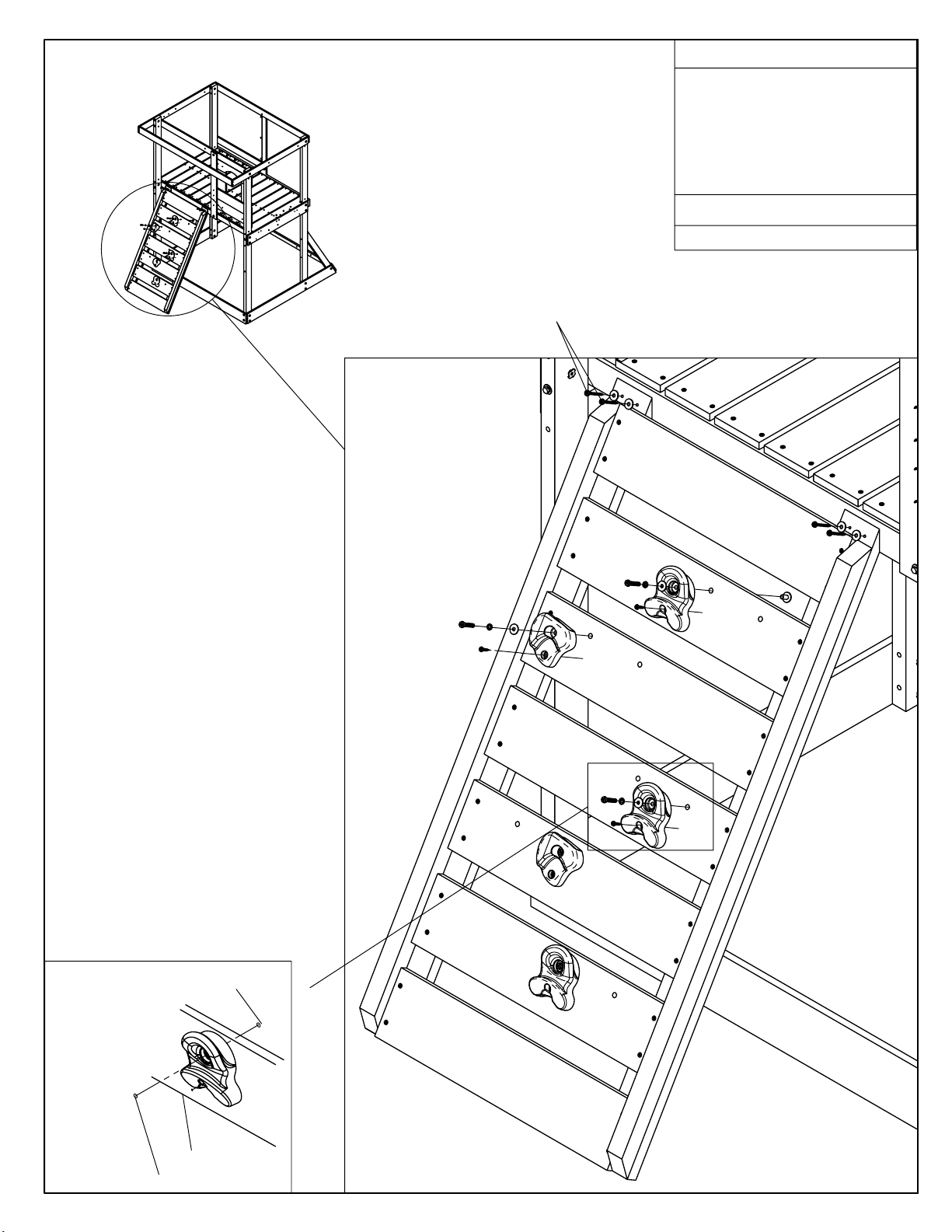
A. Pull rope through holes at top
and tie a knot under deck. Spacing
between top rung and edge of
board must be greater than 9-1/2"
B. Pull rope through hole at bottom
and tie knot, making sure that
spacing between rung and edge of
board is greater than 9-1/2".
C. IMPORTANT!
tighten loose rope ends at top of
rope ladder, and cut excess Plastic
Ties, making sure to round the sharp
edges.
Plastic Ties.
Keep rope tight to remove slack
Keep 1" space between
use (6)plastic ties
B
HARDWARE LIST
6 Plastic Ties
ACCESSORY LIST
1 Rope Ladder
A
1"
C
Make sure this
knot is tight to
the Floor Back
before attaching
Plastic Ties.
View from under Fort
Must be greater
than 9-1/2"

11A
23
1/4 x 3"
Lag Screw
Attach Seat/Table Supports on the inside
of the Fort Posts on the slide side. Drill (2) pilot
holes approximately 18" up from the ground then
attach only (2) 1/4 x 3" Lag Screws (1/4" Washer)
through center holes of Supports.
Drill 1/8" holes into Supports using Seat as guide.
Attach Seat with (4) 1/4 x 3" Lag Screws (1/4" Washer)
and tighten.
Pivot seat down 90 degrees, then
tighten Lag Screws attached to Posts.
5/4 x 6 x 34-1/4"
Cafe Seat
WOOD PARTS LIST
2 pcs 2x6x16¾" Seat Table Support
1 pc 5/4x6x34¼" Cafe Seat
HARDWARE LIST
6 pcs 1/4x3" Lag Screw
6 pcs 1/4" Flat Washer
Fort Post
Lag Screw
Flat Washer
2 x 6 x 16-3/4"
Seat/Table Supports
Lag Screw Assembly
Use factory drilled
holes as guides &
drill 3/16" pilot holes.
Factory drilled hole

11B
24
Make sure the seat is level and under the fort.
Children seated at the table should be facing out.
using the (4) remaining factory holes Drill 1/8" holes
as guides. Holes should be centered on the Post.
Secure with the (4) 1/4 x 3" Lag Screws (1/4" Flat Washer)
and tighten.
Secure CE Table Tops with (8) #8 x 1-1/2" Wood Screws.
WOOD PARTS LIST
2 pcs 1x6x34-1/4" CE Table Top
HARDWARE LIST
4 pcs 1/4x3" Lag Screw
4 pcs 1/4" Flat Washer
8 pcs #8x1-1/2" Wood Screw
#8 x 1-1/2"
Wood Screw
Supports
1 x 6 x 34-1/4"
CE Table Top
1/4 x 3" Lag Screw
with 1/4" Flat Washers

12
25
Mount slide to deck, centred on opening.
First drill 1/8" pilot holes through deck into centre of
Slide Brace and attach with screws
Note: Place slide in the centre of the
platform as shown.
#12 x 1" middle screw fastens to the floor joist.
#12 x 1"
Pan Screw
WOOD PARTS LIST
2 pcs 2x2x12-1/2" Sl Brace
HARDWARE LIST
4 pcs #12x2" Pan Screw
1 pc #12x1" Pan Screw
ACCESSORY LIST
1 Slide
#12 x 2"
Pan Screw
Slide
2 x 2 x 12-1/2"
Sl Brace
Floor Joist
(Hidden)
#12 x 2" Pan Screw
fastens through
deck and into
SL Brace on both
sides.

13
26
Stakes Installation
•Use a scrap wood piece in between the top of the Ground Stake &
the Sledge Hammer to protect the stake from damage.
•Stakes are to be secure to the posts and the ground.
•Firmly anchor unit to ground before use.
•Check for looseness, re-secure and replace if necessary.
•
DO NOT USE CONCRETE OR OTHER MATERIALS FOR ANCHORING STAKES!
•Drive Ground Stakes into the ground, making sure that the ground is
firm underneath the stakes.
•Using (2) Wood Screws, attach each stake to the corresponding
post as shown below.
WOOD PARTS LIST
5 pcs 2x2x14" Ground Stakes
HARDWARE LIST
10 pcs #8x2-1/2" Wood Screw
Drive 2 x 2 x 14"
Ground Stakes into
firm soil and attach to
SW Posts, Post, Ground
Diagonal using (2)
screws each.
Drive one Stake
and attach to
back of Rock Wall.
Sample Ground Stake Installation
Drill Pilot
Holes. Use
Stake as
guide.
#8 x 2-1/2"
Wood Screw
Ground level
(Drive stake10½"
into ground)

14
27
5/16 x 3¾"
Eyebolt
5/16 Flat
Washers-zinc
5/16 Lock
Nut-zinc
5/16 x 6"
Hex Bolt
5/16 Flat
Washers
ACCESSORY LIST
1Glider Seat
4 Glider Ropes with Chain
2 Glider Handles
2 Belt Swings
HARDWARE LIST
2 pcs 5/16x6" Hex Bolt
4 pcs 5/16" Flat Washer
8 pcs 5/16" Flat Washer-zinc
6 pcs 5/16" Lock Nut-zinc
•Assemble Glider Handles to Seat as shown with
6" Hex Bolt, two Flat Washers and one
Zinc Lock Nut. Tighten the Zinc Lock Nut until the
bolt threads are flush. Repeat for other Handle.
•Attach the Glider Eyebolts to the Glider
Handles using the hardware as shown.
DO NOT over tighten the Nut. Overtightening
can damage the Glider and cause it to collapse
during use. Check assembly frequently making
sure that the nut stays in place. Replace
hardware if it loosens repeatedly.
Hang swings from Swing Hangers using the chains
at the top to adjust heights accordingly.
Glider Seat
IMPORTANT! Before playing, check that all
hardware is tightened correctly and no bolt
threads are protuding. To prevent these sharp
edges, we have provided extra flat washers that
can be added to eliminate this condition.
Periodically, check hardware and tighten if
required. Add an additional washer if the bolt
threads start to protrude.
Glider Handle

ATTENTION
28
*During peak play season, periodically check
and re-tighten all hex bolts, lag screws, and wood screws
to ensure safety. Do not over-tighten to avoid crushing
wood.
*Thoroughly read instructions and the owners manual
before using play center.
*Maintain assembly instructions for future reference.
FILL THIS OUT BEFORE YOU DISCARD YOUR CARTONS.
YOU WILL NEED THIS INFORMATION IF YOU CALL
CONSUMER RELATIONS DEPARTMENT.
PRODUCT NUMBER:
DATE STAMP:
(BOX No. 1)
(BOX No. 2)
(BOX No.3)
(BOX No. 4)
 Loading...