

SOLOMON DVM1821Z-A0, DVK1821Z-A0 Datasheet
SOLOMON SYSTECH
SEMICONDUCTOR TECHNICAL DATA
Rev 0.1
08/2000
Copyright © 2000 SOLOMON Systech Limited
Product Information
SSD1821Z Development Kit
DVK1821Z-A0 is a demonstration of SSD1821Z working on a (128 X 80 + 1 icon line)
panel. It is intended to help users expedite their design-in of SOLOMON LCD driver.
PACKAGE CONTENTS
DVK1821Z-A0 consists of the following:
1) LCD Module (128 X 80 + 1 icon line) (DVM1821Z-A0)
2) LCD Drawing (optional)
3) Programmed 8051 MCU Board (EVM89C52-A0)
4) 8051 MCU Board Schematics (EVM89C52-A0)
5) Demo Program in C Language (PRG1821Z-A0)
SYSTEM REQUIREMENT
DVK1821Z-A0 is good enough to serve as a standalone demo. 2 X AA 1.5V battery
is required for normal operation. For engineering evaluation on the LCD driver and/or
LCD panel, a 8051 Incircuit emulator (ICE) is required. The one Solomon Systech is
using is EMMIT 8051 ICE from Syber Electronics Co Ltd. User can get its information
from the email: syber@public1.pt
LCD MODULE
Table 1 DVM1821Z-A0 pin assignment
Pin Number
1 2 3 4 5 6 7 8 9 10 11 12 13 14 15 16 17 18 19 20 21 22 23 24
LCD Module
VDD
RES
PS1
D/C
R/W
CS1
VSS
D0
D1
D2
D3
D4
D5
D6
D7
E
NC
VSS
NC
NC
NC
NC
NC
NC
8051 MCU
Board
VOUT
PA-04
PA-05
PA-01
PA-07
PA-06
GND
PB-00
PB-01
PB-02
PB-03
PB-04
PB-05
PB-06
PB-07
PA-00
VOUT
GND
+9V
P34
P35
P36
P37
NC
DVK1821Z-A0
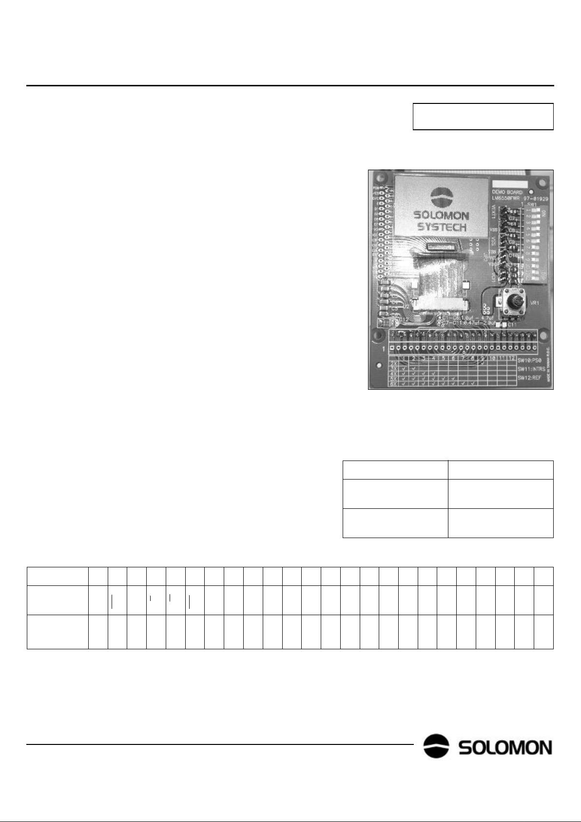
Figure 1 DVM1821Z-A0 outlook
The LCD module has been configured as follows
1) size: 128 X 80 + 1 icon line
2) COG Package
3) 6X DC-DC converter to generate VEE
4) Internal feedback resistor which is software programmable is used to
generate VL6.
5) Parallel interface
6) 24 pins single inline (SIL) header is used to connect 8051 MCU Board to LCD
Module. Please refer to Table 1 for pin assignment.
7) DIP SW 1-9 are to control the DC-DC conveter. SW 10 is the PS0 setting,
turn off in parallel mode. SW 11 & 12 are for internal testing only, please turn
off for normal use.
ORDERING INFORMATION
Item Ordering Part Number
SSD1821Z Develop-
ment Kit
DVK1821Z-A0
SSD1821Z Development Module
DVM1821Z-A0
2
SOLOMON
DVK1821Z-A0
Rev 0.1
08/2000
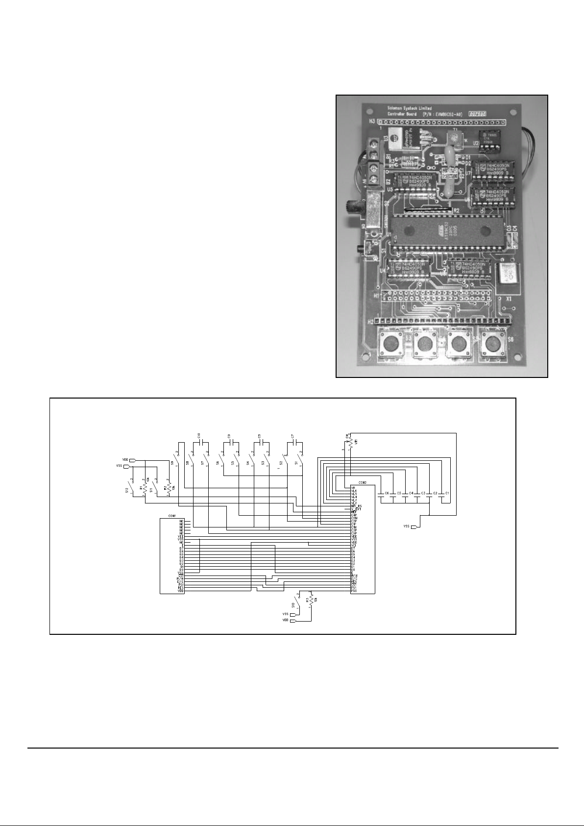
8051 MCU BOARD
The 8051 MCU Board is powered up by 2 X AA 1.5V battery. A 2X DC converter (ICL7660) is used to generate 4.8V to supply 8051 MCU. This voltage is
also regulated by LM317 to generate VOUT (adjustable from 1.8V to 3.5V)
which in turn powers up solomon LCD driver. All logic output from 8051 are
down-converted from 4.8V to VOUT through 74HC4050 non-inverting buffer.
User can change VOUT by tuning T1 (1K trimmer).The MCU board is configured
to run at a speed of 4MHz. 4 dummy keys are reserved for developing userinteractive application such as tuning contrast.
Figure 2 EVM89C52-A0 outlook
Figure 3 DVM1821Z-A0 schematics

3
SOLOMON
DVK1821Z-A0 Rev 0.1
08/2000
PROGRAMMING NOTE
/*__________________________________________________________________________*/
/* Device: DVK1821Z-A0 */
/* Descp: 1821 Demo in parallel interface */
/* LCM: 128x81 */
/* Structure: A) Hardware Interface */
/* B) Command Table per device */
/* C) Global Variables Definition */
/* D) Hardcoded Graphics */
/* E) Function Prototypes */
/* F) Main Function */
/* */
/* Remark: PS0 is hardwire on DVM1821Z-A0 by DIP SW, PS1 is programable pin*/
/*__________________________________________________________________________*/
#include "reg51.h"
#define controlport P0
#define dataport P1
/****************************************************
* A) HardWare Interface *
* *
* PORT A 7 6 5 4 3 2 1 0 *
* RW CS PS1 RES -- -- DC E *
* *
* E and PS may be tied high *
* *
* PORT B 7 6 5 4 3 2 1 0 *
* D7 D6 D5 D4 D3 D2 D1 D0 *
* *
****************************************************/
/****************************************************
* B) Command Table per device *
****************************************************/
#define DisplayOff 0xAE
#define DisplayOn 0xAF
#define DisplayStart 0x40
#define PageAddr 0xB0
#define ColAddrHi 0x10
#define ColAddrLo 0x00
#define SegRemapOff 0xA0
#define SegRemapOn 0xA1
#define NormalDisp 0xA6
#define ReverseDisp 0xA7
#define ExitEntireD 0xA4
#define EntEntireD 0xA5
#define EnterRMW 0xE0
#define ExitRMW 0xEE
#define SWRest 0xE2
#define ComRemapOff 0xC0
#define ComRemapOn 0xC8
#define PwrCtrlReg 0x28
#define OPampBuffer 0x01
#define IntReg 0x02
#define IntVolBstr 0x04
#define IntRegRatio 0x20
#define ContCtrlReg 0x81
#define CmdMuxRatio 0x48
#define CmdBiasRatio 0x50
#define DispOffset 0x44
#define IconModeOn 0xA3
#define IconModeOff 0xA2
#define NlineInver 0x4C
#define DCDCconver 0x64
#define PowersavStandby 0xA8
#define PowersavSleep 0xA9
#define PowersavOff 0xE1
#define InterOsc 0xAB
#define Device SSD1821 /* device under demo */
 Loading...