

Solo SL4848-RR, SL4848-VR, SL4848-LR, SL4848-RR-D, SL4848-VR-D Quick Start Manual
...
3505 HUTCHINSON ROAD
CUMMING, GA 30040-5860
Quick Start GuideQuick Start Guide
Quick Start GuideQuick Start GuideQuick Start Guide
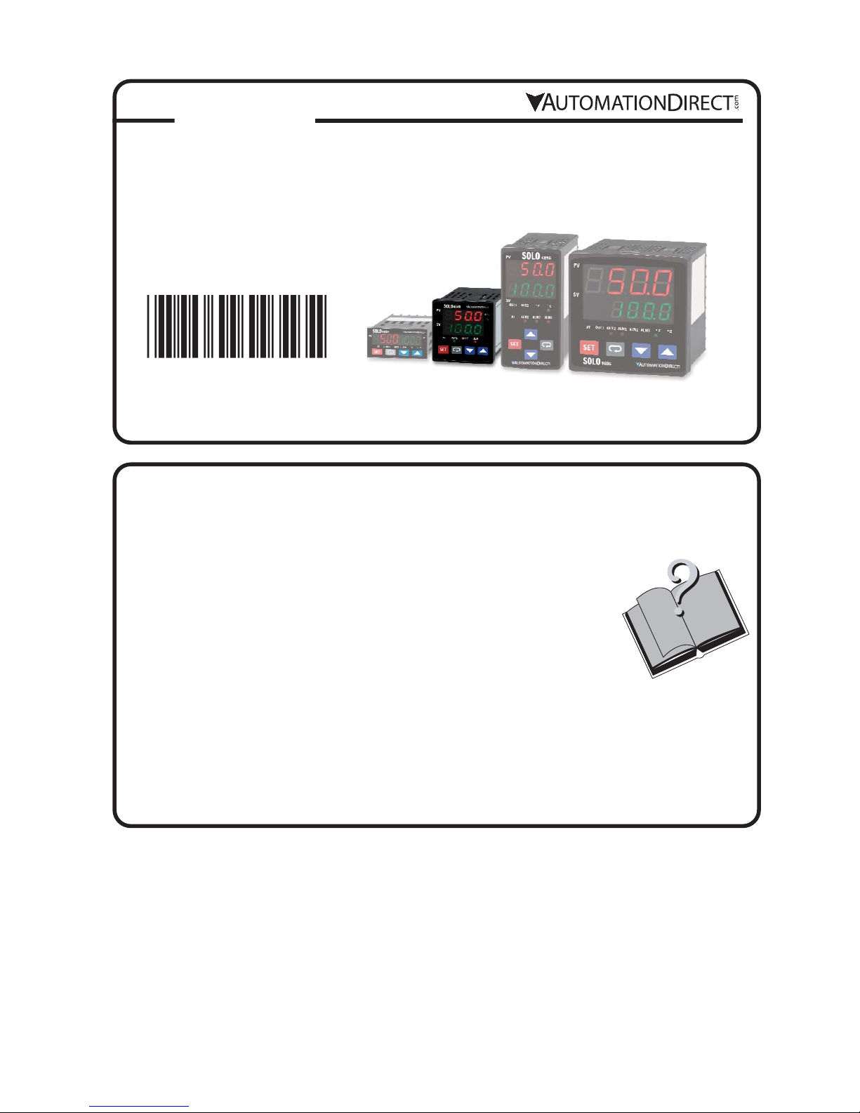
SOLO Temperature Controller
SL4848 Series
SOLO
This Quick Start Guide provides basic information on setting up the SOLO temperature controller. For
advanced setup and communication control as well as free configuration software visit the
AutomationDirect web site at www.AutomationDirect.com.
Product Support and Configuration Software
• For product support, specifications, and installation troubleshooting, a complete
User Manual can be downloaded from the On-line Documentation area of the
AutomationDirect web site.
• For additional technical support and questions, call our Technical Support team
@ 1-800-633-0405 or 770-844-4200.
• Configuration software for the SOLO controller is available for free download
at www.AutomationDirect.com. The software allows communication and
programming for up to four controllers at the same time. Parameters, process
values, set points and temperature changes can be monitored with the software. The setup data can be uploaded to the user’s PC via RS-485 communication. The user can monitor the temperature changes of the
controllers from the “PV Monitor” Display.
2015-04-20
5011654407-S447
Safety Information
WARNING: To minimize the risk of potential safety problems, you should follow all applicable local and national
codes that regulate the installation and operation of your equipment. These codes vary from area to area and it is
your responsibility to determine which codes should be followed, and to verify that the equipment, installation, and
operation are in compliance with the latest revision of these codes.
Equipment damage or serious injury to personnel can result from the failure to follow all applicable codes and standards. We do not guarantee the products described in this publication are suitable for your particular application,
nor do we assume any responsibility for your product design, installation, or operation.
If you have any questions concerning the installation or operation of this equipment, or if you need additional information, please call us at 1-800-633-0405 or 770-844-4200.
This publication is based on information that was available at the time it was printed. At Automationdirect.com®
we constantly strive to improve our products and services, so we reserve the right to make changes to the products and/or publications at any time without notice and without obligation. This publication may also discuss
features that may not be available in certain revisions of the product.
WARNING! Electric shock danger
1. To prevent electric shock, do not touch the AC terminals while the power is supplied to the controller.
This controller is an open-type temperature controller. Make sure to evaluate any dangerous application in which
a serious human injury or serious property damage may occur.
1. Always use recommended solder-less terminals: Fork terminal with insolation (M3 screw, width is 7.0mm, hole diameter 3.2mm). Screw size: M3 x 6.5 (With 6.8 x 6.8 square washer). Recommended tightening torque: 0.4 Nm (4kgfcm).
Applicable wire: Solid/twisted wire of 2 mm, 12AWG to 24AWG. Choose AutomationDirect part numbers BM-00120,
BM-00220 or BM-00320 depending on wire size. Be sure to tighten them properly.
2. Protect the controller from dust or foreign objects to prevent controller malfunction.
3. Do not modify or disassemble the controller.
4. Do not connect anything to the “Not used” terminals.
5. Make sure all wires are connected correctly.
6. Do not install and/or use the controller in places subject to: (a) Dust or corrosive gases and liquid (b) High humidity (c)
Vibration and shock (d) EMI / RFI (e) high temperature.
7. Turn power off when wiring or changing a temperature sensor.
8. Be sure to use wires that match the thermocouple types when extending or connecting the thermocouple wires.
9. Use wires with correct resistance when extending or connecting a platinum resistance thermometer (RTD).
10. Keep the wire as short as possible when wiring a platinum resistance thermometer (RTD) to the controller and route
power wires as far as possible from load wires to prevent interference and induced noise.
11. This controller is an open-type unit and must be placed in an enclosure away from high temperature, humidity, drip-
ping water, corrosive materials, airborne dust and electric shock or vibration.
12. Make sure power cables and signals from instruments are all installed properly before energizing the controller,
otherwise serious damage may occur.
13. To prevent electric shock, do not touch the terminals in the controller or try to repair the controller when power is
applied.
14. Use a soft, dry cloth to clean the controller. Do not use acid or alkaline liquids for cleaning.
15. This instrument is not furnished with a power switch or fuse. Therefore, if a fuse or power switch is required, install
the protection close to the instrument. Recommended fuse rating: Rated voltage 250 V, Rated current 1 A. Fuse type:
Time-lag fuse
16. Note: This controller does not provide overcurrent protection. Use of this product requires that suitable overcurrent
protection device(s) must be added to ensure compliance with all relevant electrical standards and codes. (Rated 250
V, 15 Amps max). A suitable disconnecting device should be provided near the controller in the end-use installation.
5
1
AutomationDirect’s SOLO is a single loop dual output temperature controller that can control both heating and
cooling simultaneously. There are four types of control modes: PID, ON/OFF, Manual, and Ramp / Soak control.
Depending upon the particular model of controller, the available outputs include relay, voltage pulse, current, and
linear voltage. There are up to three alarm outputs available to allow seventeen alarm types in the initial setting
mode. SOLO can accept various types of thermocouple, RTD, or analog inputs, and has a built in RS-485 interface using Modbus slave (ASCII or RTU) communication protocol.
Other features include:
• 1/16 DIN panel size
• 2 line x 4 character 7-segment LED display for Process Value (PV): Red color, and Set Point (SV): Green color
• Auto Tuning (AT) function with PID control
• Selectable between °C and °F for thermocouple or RTD inputs
• 0 to 50 °C (32 to 122 °F) operating temperature range
• UL, CUL and CE agency approvals
General Description
2
Specifications
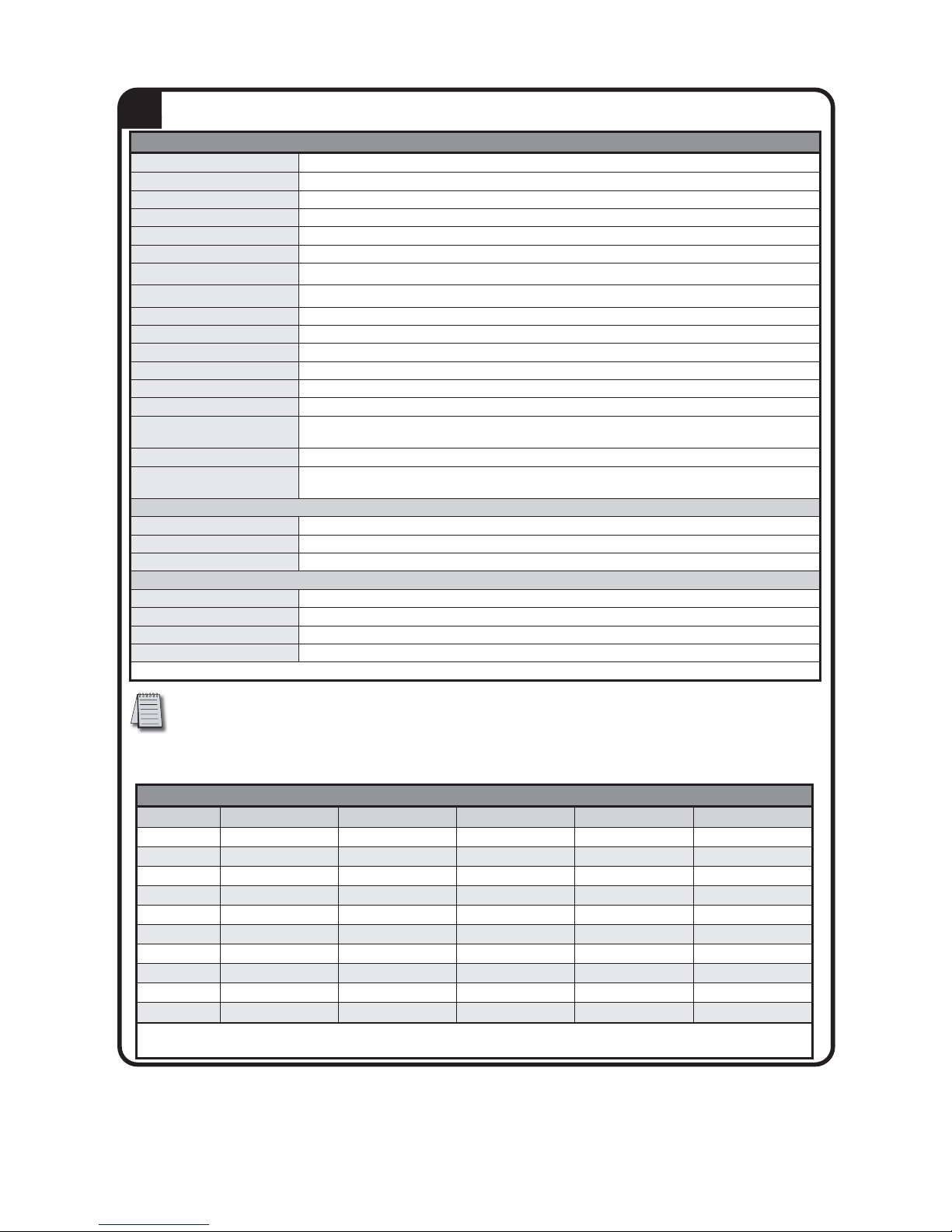
Output Specifications
Part Number Input Voltage Output #1 Output #2 / Alarm #3* Alarm #1** Alarm #2**
SL4848-RR 100 - 240 VAC Relay - SPST Relay - SPST Relay - SPST Relay - SPST
SL4848-VR 100 - 240 VAC Voltage Pulse Relay - SPST Relay - SPST Relay - SPST
SL4848-CR 100 - 240 VAC Current Relay - SPST Relay - SPST Relay - SPST
SL4848-LR 100 - 240 VAC Linear Voltage Relay - SPST Relay - SPST Relay - SPST
SL4848-RR-D 24 VDC Relay - SPST Relay - SPST Relay - SPST Relay - SPST
SL4848-VR-D 24 VDC Voltage Pulse Relay - SPST Relay - SPST Relay - SPST
SL4848-CR-D 24 VDC Current Relay - SPST Relay - SPST Relay - SPST
SL4848-VV 100 - 240 VAC Voltage Pulse Voltage Pulse Relay - SPST Relay - SPST
SL4848-CV 100 - 240 VAC Current Voltage Pulse Relay - SPST Relay - SPST
SL4848-LV 100 - 240 VAC Linear Voltage Voltage Pulse Relay - SPST Relay - SPST
*Output #2 can be configured as control output #2 or as Alarm #3
**Alarm #1 and Alarm #2 have a shared common
3
*Note: The supplied 249 ohm resistor should be installed as shown in the terminal wiring diagrams in
section 7 for current input operation.
Specifications
Input Power Requirements
100 to 240 VAC 50 / 60 Hz or 24 VDC
Operation Voltage Range
85 to 264 VAC or 21.6 to 26.4 VDC
Power Consumption
5 VA Max
Memory Protection
EEPROM 4K bit, number of writes 100,000
Control Mode
PID, ON/OFF, Ramp / Soak control or Manual
Input Accuracy
Less than ± 0.2% full scale (except thermocouple R, S, & B types) Max ± 3° (thermocouple R, S, & B types)
Vibration Resistance
10 to 55 Hz, 10 m/s2for 10 min, each in X, Y and Z directions
Shock Resistance
Max. 300 m/s2, 3 times in each 3 axes, 6 directions
Ambient Temperature Range
32°F to 122°F (0°C to 50°C)
Storage Temperature Range
-4°F to 149°F (-20°C to 65°C)
Altitude
2000m or less
Relative Humidity
35% to 80% (non-condensing)
RS-485 Communication
Modbus slave ASCII / RTU protocol
Transmission Speed
2400, 4800, 9600, 19.2K, 38.4K bps
IP Rating
IP65: Complete protection against dust and low pressure spraying water from all directions.
(inside suitable enclosure)
Agency Approvals
UL, CUL, CE (UL file number E311366)
Pollution Degree
Degree 2 - Normally, only non-conductive pollution occurs.
Temporary conductivity caused by condensation is to be expected.
Input Types
• Thermocouple*
K, J, T, E, N, R, S, B, L, U, TXK (Sampling Rate: 400 ms / per scan)
• Platinum RTD
3-wire Pt100, JPt100 (Sampling Rate: 400 ms / per scan)
• Analog
0-50 mV, 0-5V, 0-10V, 0-20 mA*, 4-20 mA* (Sampling Rate: 150 ms / per scan)
Control Output Options
• Relay (R)
SPST max. resistive load 5A @ 250 VAC
• Voltage Pulse (V)
DC 14V Max, output current 40mA Max
• Current (C)
DC 4-20 mA output (Load resistance: Max 600 ⏲ )
• Linear Voltage (L)
DC 0-10V (Load resistance Min 1K⏲ )
*Note: Use only ungrounded thermocouples.
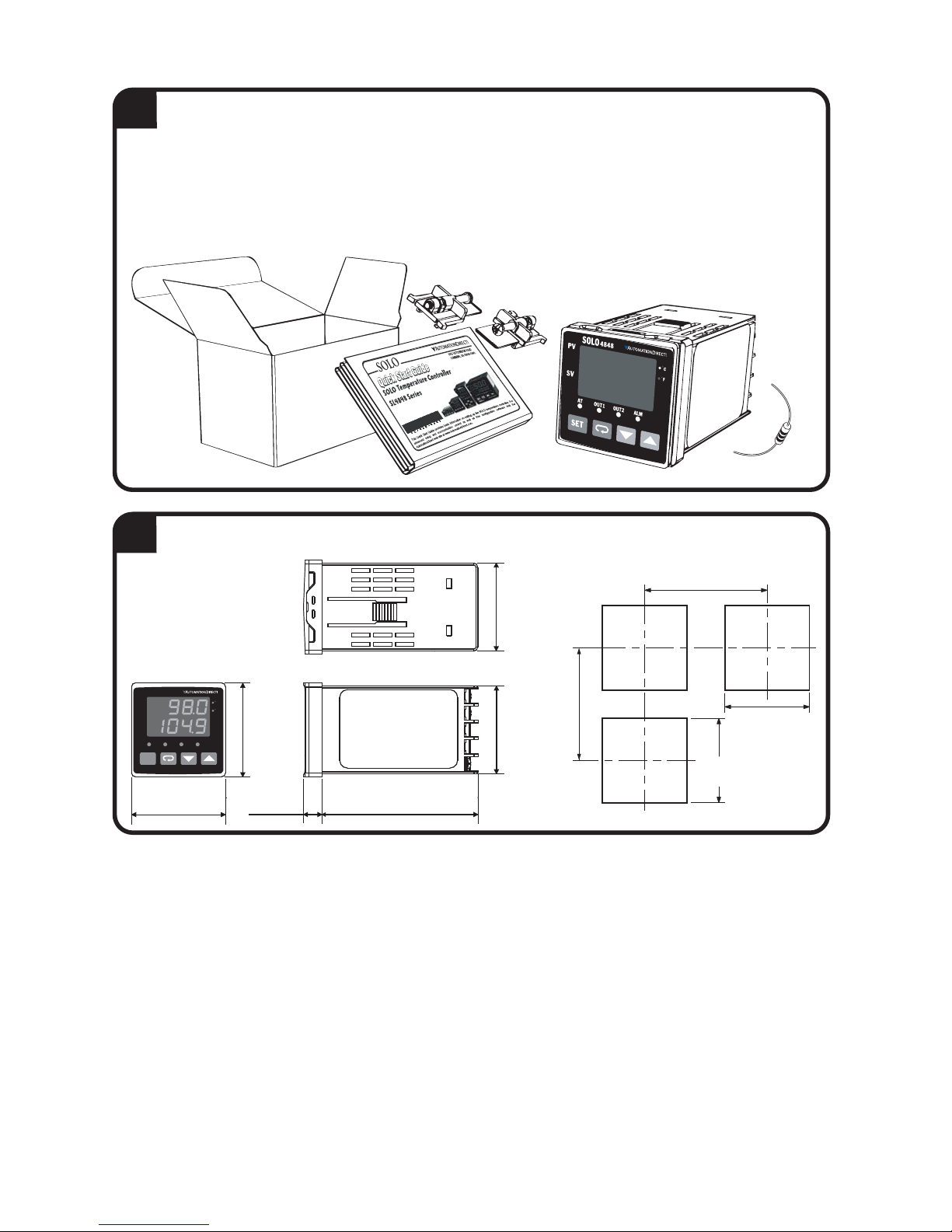
Box Contents and Unpacking Instructions
• Unpack the SOLO temperature controller from its shipping carton. Included in the carton is the temperature
controller, mounting brackets plus hardware and this Quick Start Guide.
• Inspect all equipment for completeness. If anything is missing or damaged, immediately call the Automa-
tionDirect returns department @ 1-800-633-0405.
• Inspect the part number to ensure the model received matches the output type required.
Controller and Panel Cutout Dimensions
2.36”
[60.0 mm]
2.56"
[65.0 mm]
1.77"
[45.0 mm]
+0.02
-0
+0.6
-0
1.77"
[45.0 mm]
+0.02
-0
+0.6
-0
(Min.)
(Min.)
4
5
Mounting Brackets
and Hardware
SL4848 Temperature
Controller
SL4848
Quick Start Guide
249 ohm resistor
(44.75 mm)
1.76”
4848
SOLO
PV
SV
AT
SET
(48.0 mm)
OUT1
1.89”
C
(48.0 mm)
F
1.89”
OUT2
ALM
0.37”
(9.5 mm)
3.15”
(80.0 mm)
(44.75 mm)
1.76”
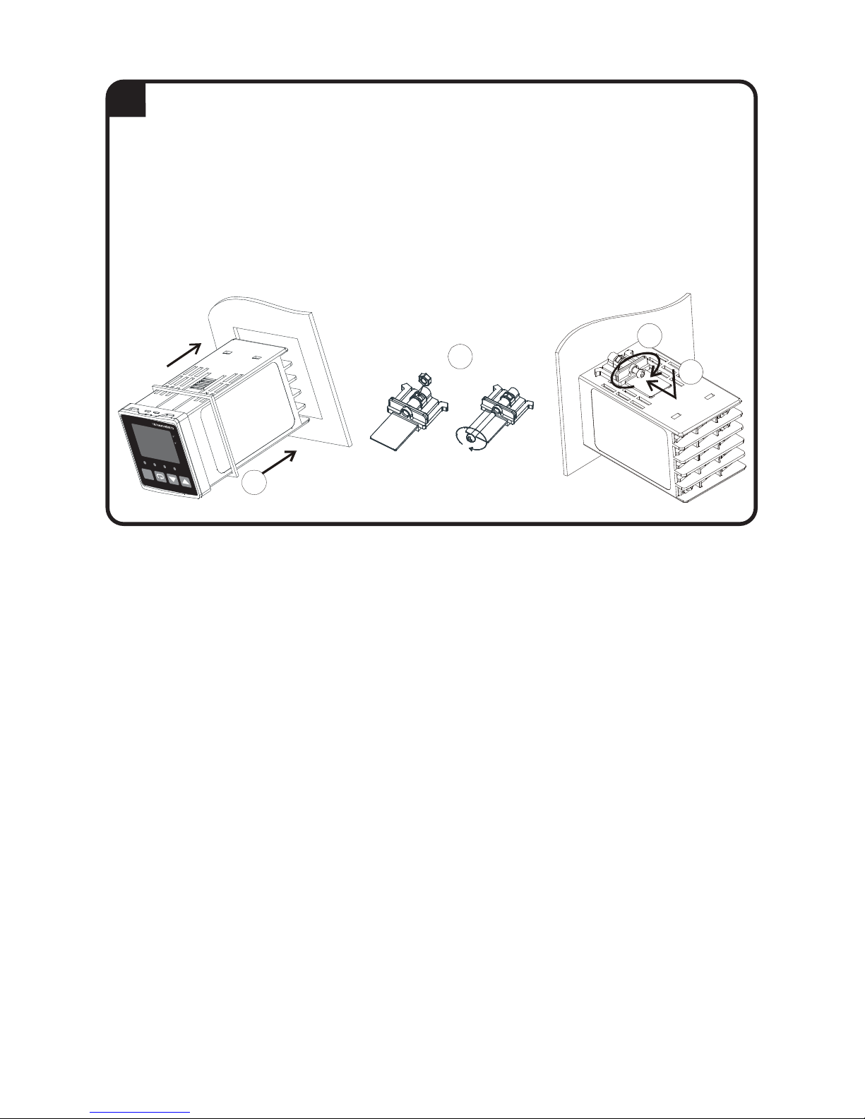
Mounting Instructions
SOLO temperature controllers can be mounted through a cutout in an enclosure or panel by using the dimensions shown in Section 5. The directions for mounting the controller through a cutout are:
1. Insert the temperature controller through the panel cutout.
2. Slide the M3X0.5 nut into the opening in the top of the mounting bracket and insert the M3X0.5 X 30mm
mounting screw in the mounting bracket.
3. Insert the mounting bracket into the mounting groove at the top and bottom of the controller, and push the
mounting bracket forward until the bracket stops.
4. Tighten top and bottom screws evenly to secure temperature controller in place.
2
6
4
3
SOLO
4848
PV
SV
C
F
AT
OUT1
OUT2
ALM
SET
1
 Loading...