

Page 1

9 450 110 english 01/2008
444 / 450
Operating manual
Important:
Read this instruction manual carefully before
putting the chain saw into operation and
strictly observe the safety regulations!
Mistblower
Page 2
ENGLISH 2
Preface
Dear Customer,
We congratulate you on your new SOLO
Mistblower and hope that you will be satisfied with this
modern tool.
A state-of-the-art single cylinder two-cycle engine
with Nikasil coated cylinder bore combined with
renowned SOLO technology of high performance with
low fuel consumption will guarantee a high degree of
application value of this product.
Read this operating manual carefully before using
the machine for the first time and at all times, strictly
observe all safety rules.
To retain peak performance of your SOLO
Mistblower over a long period we recommend you
carefully observe all maintenance instructions.
Should you require any further information after
carefully studying this manual, please contact your
specialist SOLO Dealer.
In the best interest of continued technological
progress we reserve the right to change the design and
configuration of any product without prior notice.
For that reason, no claims can be accepted with
reference to text and illustrations in this manual.
CE Declaration of conformity
SOLO Kleinmotoren GmbH, Stuttgarter Strasse 41,D71069 Sindelfingen, certifies that the following product
in the version as supplied
Description of product: Mistblower
Model/type description: 444 450
Sound power level (ISO 3744)
guaranteed 99 100 dB(A)
measured 98 99 dB(A)
complies with the following EU guide lines:
98/37/EC, 2000/14/EC and RL - 2004 - 108 EC for
electromagnetic compatibility.
Applied standards:
ISO 12100 part 1, part 2, DIN EN 294
Conformity assessment procedures: Appendix V
Serial number, Build year Î Type plate
This Declaration of Conformity will become invalid if the
product is modified, changed or altered without prior
approval.
Sindelfingen, 1
st
January 2008
SOLO Kleinmotoren GmbH Wolfgang Emmerich
Managing Director
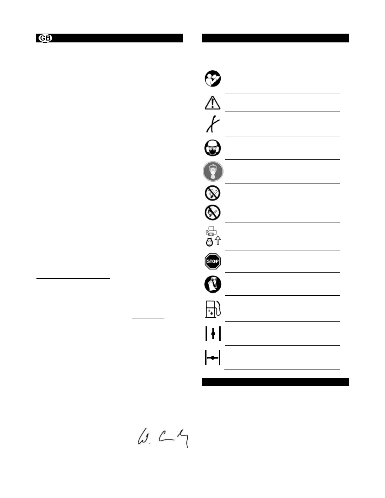
Symbols
The following symbols are used in this manual and on
the product:
Thoroughly read these operating
instructions before undertaking any
maintenance, installation and cleaning
steps
Always handle this power tool with
particular care
Prohibited
Wear eye and ear protection
A breathing mask should be worn when
using poisonous chemicals
Do not smoke
No open flame
Starting of engine
Switch off engine
Wear protective gloves
fuel mixture
choke open
choke closed
Parts subject to wear and tear
Various parts are subject to application-specific or
normal wear and must be replaced in good time, when
required. The following parts are subject to normal
wear and are not covered by the manufacturer's
guarantee:
• Air filter
• Fuel filter
• All rubber parts which come into contact with fuel
• Spark plug
• Starter
Page 3

ENGLISH 3
Index
Page
1. Important Components / Type plate ....................................................................................................... 4
2. Technical Specifications ......................................................................................................................... 6
3. Safety regulations .................................................................................................................................... 7
3.1 Correct use / Notes for General Use 7
3.2 General safety instructions 7
3.3 Personal protective equipment for your safety 7
3.4 Protection of Environment 7
3.5 Operating Hints 7
4. Maintenance and Care ............................................................................................................................. 8
4.1 General Maintenance Hints 8
4.2 Fuel-Information 8
4.3 Spark Plug 9
4.4 Preparation for Storage 9
4.5 Carburettor adjustment 9
4.6 Air Filter Maintenance 10
5. Assembly ................................................................................................................................................ 11
5.1 Assembly of misting equipment 11
5.2 Assembly of handle, spray tube and spray nozzle 11
6. Starting / Stopping the engine .............................................................................................................. 12
7. Operating Hints ...................................................................................................................................... 13
7.1 Adjustment of shoulder straps 13
7.2 Filling 13
7.3 Misting 13
7.4 Residual spray medium 14
7.5 Strainer for accessory sets 14
7.6 Checking the spray medium flow rate 14
7.7 Draining and cleaning the tank 15
7.8 Application 15
8. Maintenance Plan ................................................................................................................................... 16
9. Motorised sprayer - accessories .......................................................................................................... 17
10. For USA only: ECW Statement / Manufacturers Warranty Coverage.............................................. 17
Guarantee
The manufacturer guarantees trouble-free quality and will cover the cost of replacing parts which are found to be faulty
in material or workmanship within the prescribed guarantee period after the date of purchase. Please note that specific
guarantee conditions may vary from country to country. If in doubt, ask your equipment vendor. He is responsible for
guarantee matters.
We hope you will understand that we cannot be liable for damage resulting from the following causes:
• Non-compliance with the operating instructions.
• Neglecting essential maintenance and repair work.
• Damage caused by incorrect carburettor adjustment.
• Wear in normal use.
• Obvious overload by continuously exceeding the maximum performance limit of the product.
• Using non-authorised tools.
• Use of force, incorrect treatment, misuse and accidents.
• Damage from excessive heat due to dirt build-up around the cooling fan housing.
• Attempted adjustments and repairs by unqualified persons.
• Use of unsuitable spare parts or third party parts, if these are the cause of the defect.
• Use of unsuitable or stale fuel.
• Damage caused by using the product in the hire or rental industry.
Normal cleaning, adjustments or maintenance work fall outside the guarantee provisions.
A service centre authorised by the manufacturer must carry out all guarantee work.
Page 4
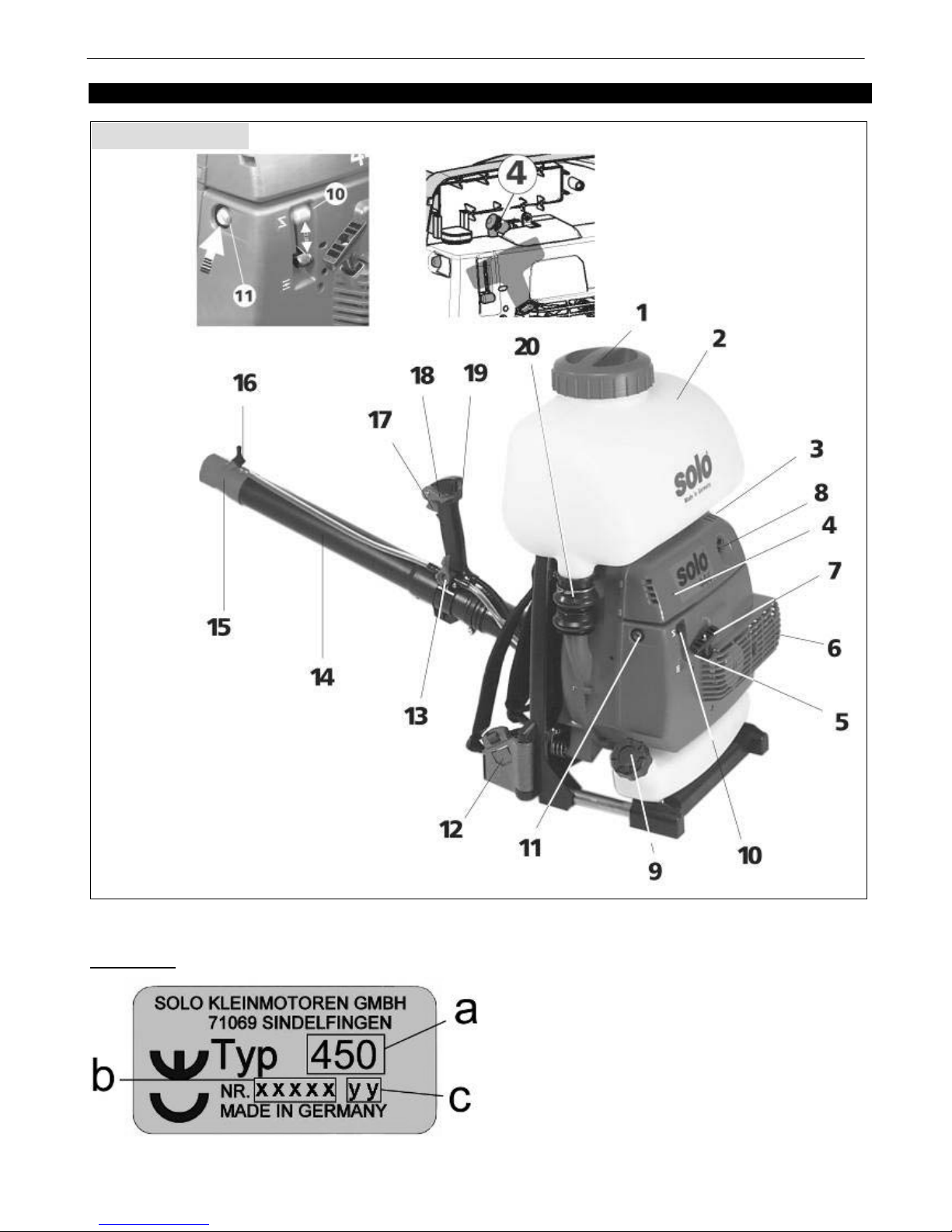
Important Components
ENGLISH 4
1. Important Components / Type plate
Type plate:
a: Type designation
b: Serial number
c: Build year (08 Î 2008)
Fig. 1a, Type 444
Page 5
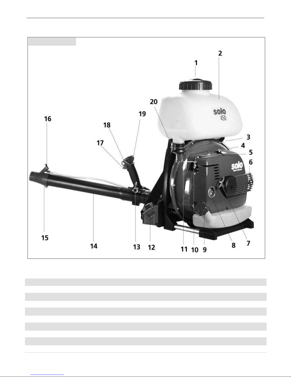
Important Components
ENGLISH 5
1. Tank lid / Filler basket with filter 11. Primer
2. Formula tank 12. Shoulder strap – quickcoupling
3. Formula outlet 13. Formula On-off tap
4. Spark plug 14. Spray tube
5. Carburetor adjustment screws 15. Spray nozzle
6. Muffler 16. Dosage sleeve
7. Starter handle 17. Throttle lever
8. Air filter cover 18. Throttle lock lever
9. Fuel tank cap 19. Stop switch
10. Choke 20. Tank ventilation
Fig. 1b, Type 450
Page 6

Technical Specifications
ENGLISH 6
2. Technical Specifications
Mistblower 444 450
Engine type SOLO single cylinder two-stroke engine
Engine capacity cm
3
40,2 53
Bore / stroke mm 40 / 32 42 / 38
Fuel tank capacity l 1,5 1,9
Fuel mix ratio: with SOLO 2T Oil
with other two-stroke oils
1:50 (2%)
1:25 (4%)
Carburettor All-position diaphragm carburettor with primer and
integrated fuel pump
Air filter cartridge Paperstyle
Ignition Electronically controlled magneto ignition, maintenance
free
Total Formula Tank Capacity l 13 13 / 21 (Typ 450-02)
Nominal Formula Tank Capacity l 12 12 / 20 (Typ 450-02)
Strain funneled mesh size mm 0,55
Residual volume which the equipment cannoot properly
apply ml
< 100
Strainer for accessory sets mesh size mm
0,32
Max. Blower Air Volume m3/h 900 1100
Weight kg 9,5 10,8
Dimensions without Spray Tube mm hight: 690
width: 500
depth: 260
hight: 690
width: 550
depth: 280
Medium idling speed rpm 2900
In determining the following values regarding the acceleration of vibrations and sound, the different operating
conditions were weighted in accordance with the current standards
Sound pressure level L
Peq
dB(A)
(EN ISO 3744)
89 90
Sound power level L
Weq
dB(A)
(EN ISO 3744)
97 99
Weighted effective acceleration a
hv,eq
(EN ISO 5349)
m/s
2
< 2
< 2
Page 7

Safty regulations
ENGLISH 7
3. Safety regulations
3.1 Correct use / Notes for General Use
• The mistblower is suitable for the application of crop protection products which have been approved by the
responsible, local Registration Authority. The output quantity can depend on the position of the spray tube.
• If the spray tube is held upwards at an angle exceeding 30 deg. from the horizontal position, the installation of a
liquid booster pump may be necessary. The booster pump is available as an accessory.
• With the use of a granulate attachment (available as special attachment- without liquid pump), the mistblower can be
used to spread granular fertilizer, fish food granules or for the spreading of grass seed.
• The mistblower, without using the formula tank, also doubles as air blower to remove fallen leaves, grass clippings,
paper, dust or snow in parks, gardens, sports arenas, parking lots or drives (without liquid pump).
• The mistblower may only be used for the jobs it has been designed for – and no other!
• Always observe all safety hints while using the machine.
3.2 General safety instructions
Some parts on the machine have been removed for transport purposes. Prior to first use, the mistblower has to
be completely assembled. (Fig.4a – 4d) This mistblower may only be started and used when completely
assembled.
Read the operating instructions carefully before placing in service and keep them in a safe place. First time users
should be instructed by the seller or an expert.
The operator is liable towards others within the operating area of the mistblower.
Only operate the mistblower when in good physical condition. Fatigue and illness lead to carelessness and
accidents. Proceed in a careful and alert manner.
Never use a machine while under the influence of alcohol or drugs.
The air exit speed from the nozzle is very high. Never point the nozzle towards persons or animals.
3.3 Personal protective equipment for your safety
To prevent injuries to head, eyes, hand, feet or damage to hearing, the following protective equipment should be
worn:
Clothing should be appropriate for the job, i.e. not too loose and not too tight to be hindering. Do not wear
work coat, shorts or sandals. The operator should not wear a scarf, a necktie or jewelry which may get caught
by branches.
Protect your face and eyes with a face guard or safety glasses.
A breathing mask should be worn when using poisonous chemicals
To avoid damage to hearing, the operator should wear suitable personal noise protection such as ear muffs, ear plugs
or similar.
Wear firm work shoes with non-slip soles.
Always observe accident prevention regulations issued by local trade organizations or workers compensation boards.
3.4 Protection of Environment
Be aware of your surroundings
• Watch out for animals which may be within your work area
• Be aware that noise is harmful to the environment. Inquire about and respect possible local rest periods.
3.5 Operating Hints
• Approach the target object with the engine at idling speed. Accelerate to full engine speed, then open formula on-off
tap.
• No other persons should be present within a circle of 15 meters from the operator. Watch out for children and
animals. Objects carried by the air stream can deflect and injure nearby persons.
• Never operate on unstable ground watch out for any obstacles such as tree stumps, tree roots, ditches etc..
• Take special care while working along slopes.
• Never touch a hot exhaust.
Page 8
Maintenance and Care
ENGLISH 8
4. Maintenance and Care
4.1 General Maintenance Hints
After a running in period of approx. 5 hours, all
accessible screws and nuts (except for carburetor
mixture adjustment needles) have to be checked and
re-tightened if required. Any service jobs, other than
those described in this manual, should only be carried
out by an authorized service center.
• Any cleaning, maintenance or repair jobs should
only be performed when the engine is stopped and
with removed spark plug cap. The exception, of
course, is carburetor tuning
Maintenance Guide Lines
• Any service jobs, other than those described in this
manual, should only be carried out by an authorized
service center. Only original parts may be used for
any maintenance and service work.
• Never modify your motorized mistblower – your
personal safety is at risk.
• Never service or store the machine near an open
flame.
• Regularly check the fuel tank lid for sealing and tank
ventilation. Only use recommended spark plugs.
Check ignition cable for any damage.
• Never operate a motorized mistblower with a
damaged muffler or without muffler (fire risk and risk
of damage to hearing). Do not touch hot muffler.
For transport in a vehicle, ensure the
mistblower is well secured to avoid fuel spillage.
• Completely empty the fuel tank before
extended storage or shipment.
4.2 Fuel-Information
Petrol and Oil
The engine of your motorized mistblower is a high
performance 2-cycle engine and has to be operated
with a fuel/oil mix or with a special, pre-mixed fuel for 2cycle engines available from specialized dealers.
Important: For the fuel mixture, use lead-free regular
(standard) petrol, lead-free Euro-petrol or lead-free
Super (premium) petrol. The minimum octane rating is
92 ROZ.
Mixing Ratio:
We recommend a mixing ratio of 1 part of oil to 50
parts fuel (1:50 - 2%) with the use of special 2-cycle oil
SOLO 2T Oil.
When using other 2-cycle oils we recommend a mixture
ratio of 1:25 (4%). Note: Never store fuel mixture for
longer than 3-4 weeks.
Fuel mixture table
Oil in litres Petrol in
litres
SOLO 2T Oil
2% (1:50)
Other two-stroke oils
4% (1:25)
1 0,020 0,040
5 0,100 0,200
10 0,200 0,400
Running Instructions:
For the first 5 tank fillings, also when using special 2cycle oils, use a mixing ration of 1:25 (4%)!
• Smoking or open flame is prohibited.
• Allow engine to cool before re-fueling.
• Fuel may contain solvent-like substances. Avoid
skin and eye contact with mineral products. Wear
gloves while refueling. Frequently change and clean
protective clothing. Do not inhale fuel vapors.
• Do not spill fuel or oil. In case of spillage,
immediately wipe off mistblower. Do not allow fuel
mix to contact clothing. If fuel mix is spilled on
clothing, change clothing immediately
• Ensure fuel or oil do not contaminate soil
(environmental protection). Always use a suitable
protective soil cover.
• Do not re-fuel in unventilated rooms. Fuel vapors
collect at ground level (danger of explosion).
• Transport and store fuel and oil only in approved
and clearly marked containers. Children should
have no access to fuel or oil.
• Ensure you do not inhale exhaust fumes while using
the machine. The use of the motorized mistblower is
prohibited in closed rooms.
The handling of fuel requires caution and
consideration. It is imperative that all safety
instructions are observed!
• Only refuel when the engine has been
stopped!
• Clean the area around filler inlet before refueling.
• Remove tank lid and fill fuel mix up to the lower
edge of the filler neck. Do not overfill. If possible,
always use a fuel funnel with filter.
• Replace and secure fuel tank lid.
Page 9
Maintenance and Care
ENGLISH 9
4.3 Spark Plug
The correct spark plug with thermal range 200 is
available under the following brands:
BOSCH WSR6F
CHAMPION RCJ-6Y or similar
The correct electrode gap is 0.5 mm.
Check the plug after every 50 operating hours
and replace if electrodes are worn.
4.4 Preparation for Storage
Store the motorized mistblower in a dry room. Cover
the unit and keep inaccessible to children.
Treatment with special anti-corrosion oil is not required
if the mistblower is normally used with SOLO 2T Oil
two-cycle oil in the fuel mixture.
For extended storage, completely empty the fuel tank.
4.5 Carburettor adjustment
The carburettor has been adjusted optimally at the
factory. Subject to the operational altitude (mountains
or low lying areas), the carburettor may require
readjustment.
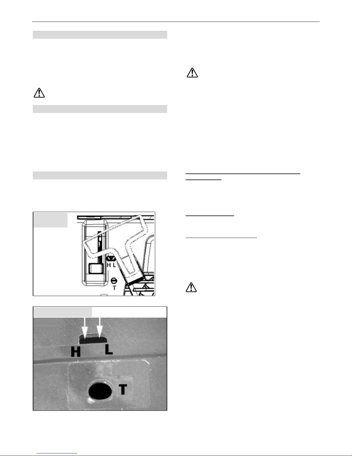
The carburettor has 3 adjusting screws:
• Idling end-stop screw "T"
• Low speed mixture screw "L"
• High speed mixture screw "H"
Only qualified mechanics must adjust the
regulating screws for idle mixture "L" and full
load mixture "H".
Turn the idling end-stop screw "T" to adjust the idling
speed in accordance with the details provided in the
specification. Use an engine rev counter for this job.
• If the idling speed is too high, turn the idling end-
stop screw "T" anti-clockwise.
• If the idling speed is too low (engine stops) turn the
idling end-stop screw "T" clockwise until the engine
runs smoothly.
If the idling speed cannot be set correctly with the idling
end-stop screw "T", request an authorised service
centre to tune the carburettor.
The following instructions are for authorised
service shops
Information about the standard settings can be
requested from the specialist workshop of our customer
service department or downloaded from our Internet
portal for specialist dealers at www.part-and-more.org.
D-CUT carburettors:
Use the D-CUT carburettor key to adjust the idle
mixture screw "L" and the full load mixture screw "H".
Carburettors with limiter caps:
The regulating screws for idle mixture and full load
mixture can only be adjusted in a limited range.
Clean the air filter before adjusting the low speed
screw!
Let the engine run warm before adjusting the engine
speed.
The carburettor is tuned for optimum engine
performance. Use a rev counter to tune the
carburettor correctly!
Do not adjust the engine to a higher speed. Excessive
engine speed can lead to major engine damage!
Fig. 2b, Type 450
Fig. 2a,
Type 444
Page 10
Maintenance and Care
ENGLISH 10
4.6 Air Filter Maintenance
The air filter separates and retains dirt before the air
reaches the combustion chamber. This reduces engine
wear.
Regular maintenance increases engine life.
Clogged air filters cause performance loss and
increased fuel consumption. This leads to a higher
toxin level in the exhaust gas and also makes starting
more difficult.
When the machine is used all day, the air filter should
be cleaned daily. In severe dust conditions clean more
often in between.
For a simple cleaning procedure we recommend
tapping the air filter.
Never use a high pressure air cleaner nor wet or
moist cleaning. Do not use solvent or oil bath
cleaners!
If engine rpm's tend to drop although the carburettor
adjustments are perfectly set, the air filter cartridge is
clogged and must be replaced by a new one
(Type 444: Order-Nr. 20 48 282)
(Type 450: Order-Nr. 20 48 280).
Never do realignments on the factory carburettor
settings in order to balance a clogged air filter system.
This procedure would cause engine damages due
overload of the engine.
Warranty claims cannot be accepted for damaged
engine parts caused by improper care and
maintenance
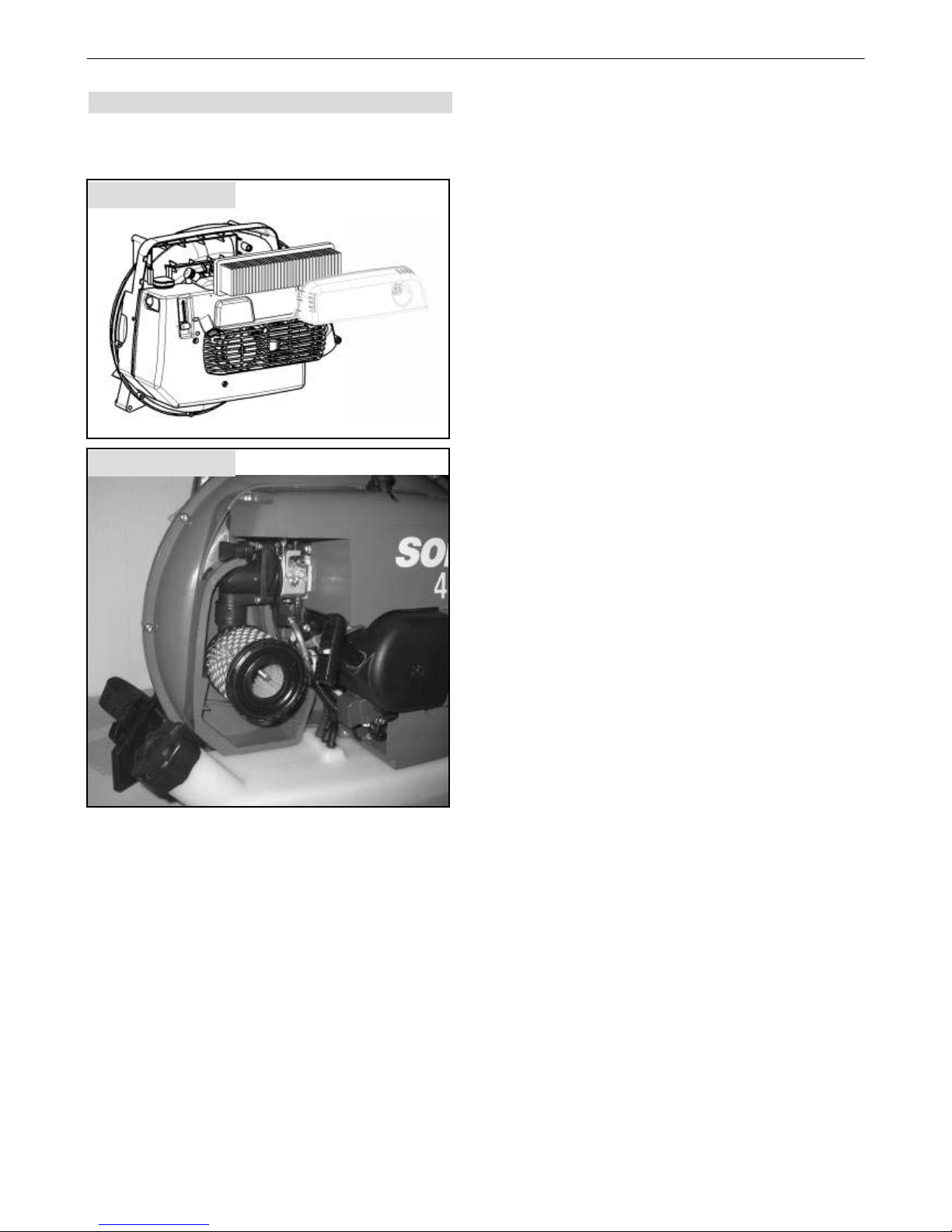
For removal of the air filter, remove filter cover.
Remove filter cover screw (Fig. 1 Pos. 8).
Fig. 3b, Type 450
Fig. 3a, Type 444
Page 11
Assembly
ENGLISH 11
5. Assembly
Completely assembly the mistblower before its first use:
5.1 Assembly of misting equipment
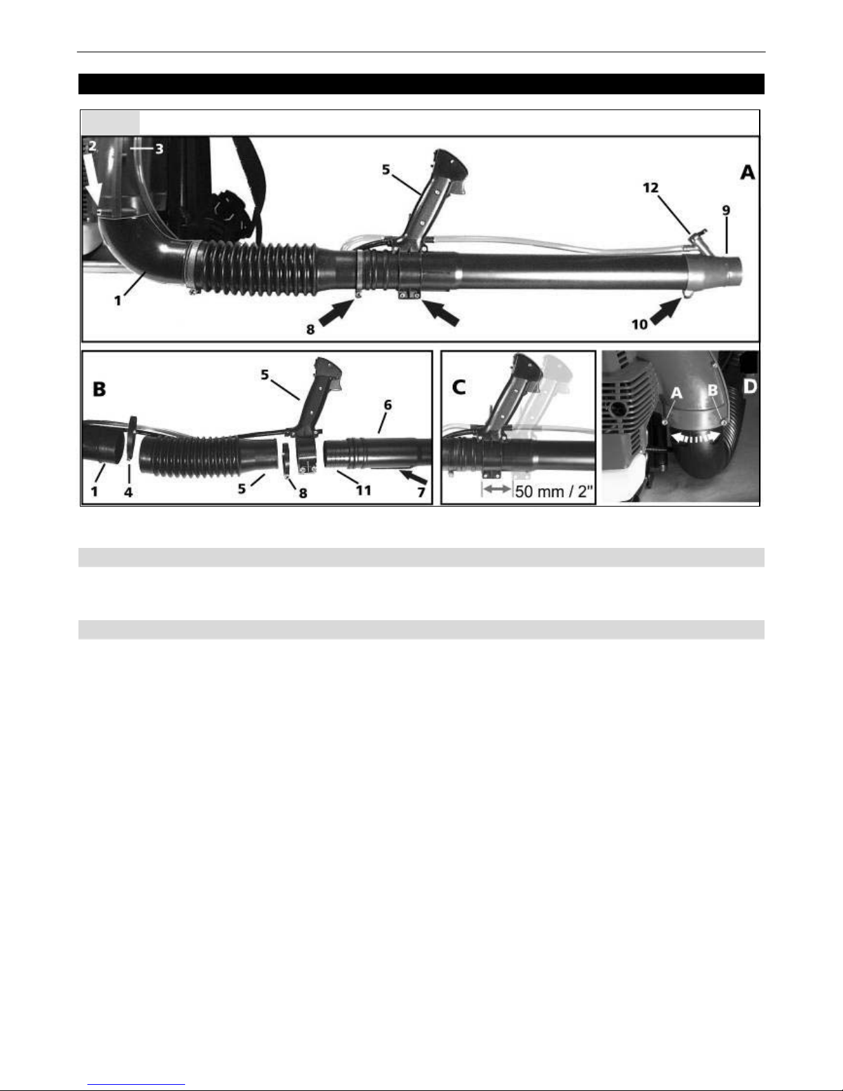
Attach the blower elbow (1) to the blower housing and secure with both screws (Fig.4D; A+B). Ensure the elbow can
swivel easily. Push pleated hose onto blower elbow and secure with clamp (4).
5.2 Assembly of handle, spray tube and spray nozzle
Push handle (5) onto spray tube (start from the front) and fix in the required position (Fig.4C). A guide (7) on the spray
tube will ensure vertical positioning.
Push the spray tube with twist coupling (11) into the pleated hose (5) until locked. Secure with clamp (8).
Note: The spray tube can be twisted and turned in the pleated hose with the handle. Ensure that all hose and cable
connections are safe and without sharp bends.
Place spray nozzle (9) on to spray tube (vertical to handle) and secure (10).
Push formula delivery hose (2 pieces) on nipple of the handle and to the spray nozzle. Secure the hose alongside the
pleated hose. Shut on/off tap (vertical position), fill some plain water in formula tank and check for any leakage.
Fig. 4
Page 12
Starting / Stopping the engine
ENGLISH 12
6. Starting / Stopping the engine
Starting with cold engine
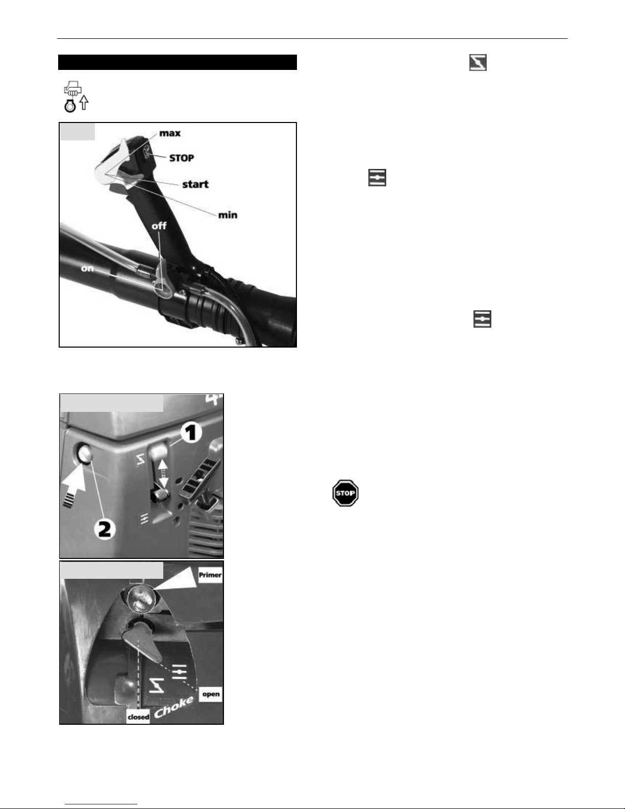
• Switch ignition switch to ”I” position and close (OFF)
formula on/off tap .
• Move throttle lock lever to ”Start” position.
• Close choke with choke lever.
• Press primer several times until fuel is visible in the
primer.
• Place your left hand on the formula tank of the
mistblower. Hold the starter handle (Fig. 1.Pos. 7)
with your right hand and pull the handle up slowly
until resistance is felt. Then pull up firmly and rapidly
until the engine ‘fires’.
• Once the engine tries to start, immediately open the
choke
and continue to start.
• When the engine runs, use the throttle lever to
accelerate to the required engine speed. For
continuous use, set the throttle lock lever (Fig. 1,
Pos. 18) in the required position for the desired
engine speed.
• To return to idling speed, either release the throttle
lever or move throttle lock lever down to ”min”
position.
Starting with warm engine after short stop
• Leave choke in ”open” position
and start engine.
Should the engine refuse to start despite several
starting attempts, the combustion chamber is most
likely flooded.
In this case we recommend you remove and dry the
spark plug (Fig.1, 4). Set the ignition switch to ”stop”
and set throttle lock lever (Fig. 1, 18) to full throttle
position ”max”. Pull over engine several times, still with
spark plug removed. This will ventilate the combustion
chamber
Replace spark plug and repeat starting procedure.
Shutting off engine
• Release throttle lever and move throttle lock lever to
”min” position.
• Move ignition switch to ”Stop” position until engine
stops.
Fig. 5
Fig. 6b, Type 450
Fig. 6a, Type 444
Page 13
Operating Hints
ENGLISH 13
7. Operating Hints
Before every use and before every start of the
mistblower check and ensure the machine is in good
and safe condition. (throttle operation, ignition switch,
safety devices, shoulder strap and check for fuel
leaks).
• During the starting procedure and while operating
the mistblower, the operator must have secure
footing and have a safe body position.
• The engine starting site should be at least 3 meters
away from the refueling site.
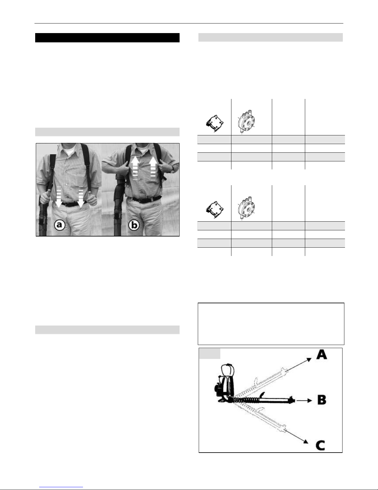
7.1 Adjustment of shoulder straps
Place the mistblower on the back and connect to quick
couplings (Fig.1, 12) on either side.
The straps can be adjusted to the required length with
friction slides. Simply pull down both strap ends to
tighten straps (a).
Strap tension can be released by lifting both friction
slides (b).
Note:
The shoulder straps are correctly adjusted when the
back plate of the mist-blower rests firmly against the
back of the operator.
7.2 Filling
• For filling the equipment, always use the strainer
inside the filler neck and observe the filler area
through the filling process.
• Prevent any direct contact between the external
filling hose and the tank contents.
• The spray medium must not be allowed to enter the
water mains through backlash.
• When filling with spray medium ensure, that neither
environment, nature nor the water mains ever make
contact with the spray medium.
• Prevent the tank from overflowing, the
contamination of public water, foul water and
drainage channels.
• The strainer has a mesh size of 0.55 mm. Only use
original SOLO strainers, part no.: 42 00 104 with
standard mesh size.
7.3 Misting
Open formula on/off tap: Lever in horizontal position –
ON – (Fig.5).
Shut formula on/off tap: Lever in vertical position –OFF
- (Fig.5).
The liquid output volume is adjusted by turning the
dosage sleeve to different positions.
Misting Output Guide Type 444
Dosage
sleeve
A *) B C
Position 1 0,8 l/min 0,6 l/min 0,7 l/min
Position 2 1,4 l/min 0,9 l/min 1,2 l/min
Position 3 1,9 l/min 1,8 l/min 1,9 l/min
Position 4 2,6 l/min 2,4 l/min 2,5 l/min
Misting Output Guide Type 450
Dosage
sleeve
A *) B C
Position 1 0,8 l/min 0,6 l/min 0,7 l/min
Position 2 1,4 l/min 1,0 l/min 1,2 l/min
Position 3 1,9 l/min 1,9 l/min 1,9 l/min
Position 4 2,6 l/min 2,6 l/min 2,9 l/min
*) The delivery values when using a liquid pump
(accessories) apply to every position of the spray
wand.
Note: The liquid pump attachment comprises a special
metering body, which should be installed when using a
liquid pump.
Please note: When using a liquid pump, ensure that
the tank contains sufficient liquid. The liquid pump
can sustain severe damage, if it is permitted to run
dry. When using the equipment as a mister and as
blower, remove the pump for that reason.
Fig. 7
Fig. 8
Page 14
Operating Hints
ENGLISH 14
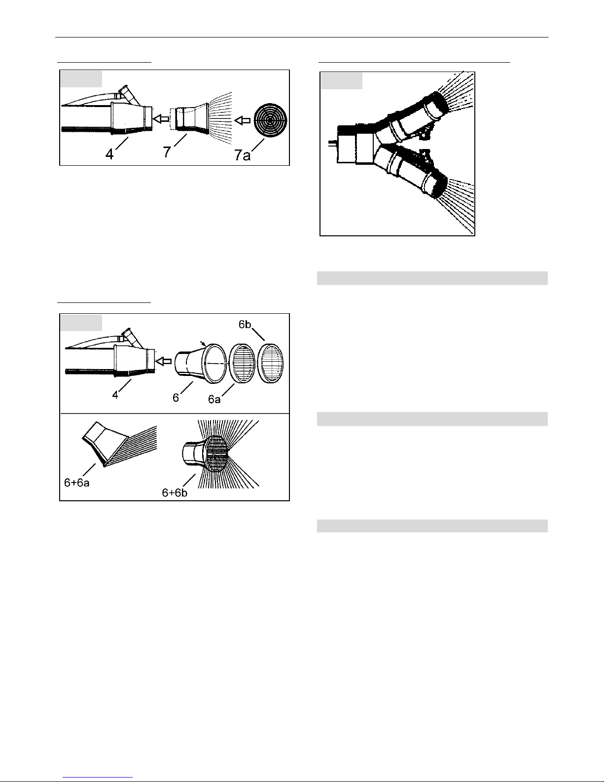
Wide-range nozzle (7):
When spraying plants and trees we recommend fixing
the wide-range nozzle (7) onto the red standard nozzle
(4). This ensures that a large area can be sprayed at
one time. Push the wide-range nozzle onto the
standard nozzle, until the bead engages.
In narrow spaces and for aftercare, we recommend
placing the wide-angle grille (7a) onto the wide-range
nozzle. This ensures that the spray velocity is reduced
and the spray is applied more widespread, to prevent
damage to leaves.
Nozzle attachment (6):
The nozzle attachment (6) is positioned onto the
standard nozzle (4) with the selected grille.
Use the dual grille (6a) when spraying cultures in rows
(e.g. vines, tomatoes, nurseries), to achieve a good
covering on the underside of the leaves.
The deflector grille can be replaced with a dual grille
(6b). The dual grille provides a 90° - 110° spray
pattern. The dual grille is usually used for spraying two
rows at a time. The deflector grille and the dual grille
can be placed onto the external diameter of the nozzle,
until the bead engages.
Dual nozzle (accessories, part no.: 49 00 137):
Remove standard nozzle (4) from the spray wand and
push the dual nozzle onto the spray wand.
7.4 Residual spray medium
Switch off the appliance as soon as no further liquid is
expelled, when the metering body is correctly
positioned for spraying, or air bubbles are visible inside
the lance supply hose.
The tank will then contain less than 100 ml residual
medium.
If you don’t want to refill the tank with spray medium
and you want to terminate spraying, dilute the residual
medium with 2 l of water. Dispose of this solution on
the treated area.
7.5 Strainer for accessory sets
When using the liquid pump (accessory part no.:
type 444 Î 44 00 114, type 450 Î 44 00 235) or the
ULV accessory (part no.: 49 00 479), a strainer is
integrated into the tank connector.
The strainer has a mesh size of 0.32 mm. Only use
original strainer part no.: 25 00 198 with standard mesh
size when replacing the strainer.
7.6 Checking the spray medium flow rate
At the beginning of the spraying season, check whether
the equipment flow rate (l/min) still corresponds to the
„Guide values“ table (see also item „Maintenance
schedule“).
For this, fill the equipment up to the maximum marker
with water, start using the equipment and spray for one
minute exactly at maximum operating pressure. Then
measure the water volume required to bring the water
level back up to the maximum marker.
The actual volume measured represents the flow rate
of the equipment in l/min at maximum operating
pressure.
It should not deviate by more than 10 % from those
listed in the „Guide values“ table. Should the actual
value be too low, sediments inside the metering body
may be the cause. Clean the corresponding parts and
repeat the checking procedure.
Fig. 9
Fig. 10
Fig. 11
Page 15
Operating Hints
ENGLISH 15
Should the actual value be too high, the metering body
may be worn or damaged. In that case, replace the
metering body with a new one (part no.:40 74 165).
When using accessory sets (liquid pump part no.:
type 444 Î 44 00 114, type 450 Î 44 00 235 or ULV
accessory, part no.: 49 00 479) a strainer will be
integrated into the tank connector.
In that case, an incorrect flow rate can also be due to a
contaminated or worn strainer.
Clean or replace the contaminated/worn strainer (part
no.: 25 00 198).
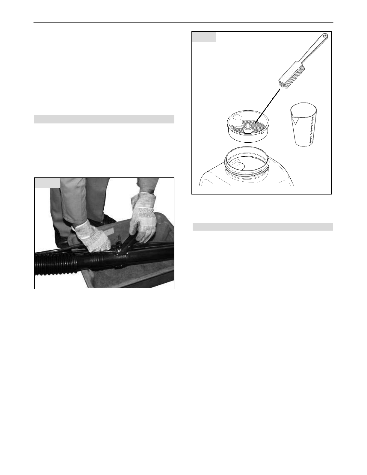
7.7 Draining and cleaning the tank
For cleaning purposes, the tank can be fully drained
into a suitable container via the supply hose.
For this, the engine must be cooled down.
Position the equipment onto a stable higher support, so
that the spray medium can drain into a suitable
container below.
Above the container, pull the supply hose from the
shut-off valve.
If required, tip the equipment slightly to drain the tank
completely.
Ensure that the spray medium does not run over the
equipment (especially the engine), but drains directly
into the suitable container.
Dispose of residual spray medium correctly at disposal
sites licensed for specialised waste.
Empty the spray medium tank daily after work and flush
thoroughly with water.
Observe cleaning instructions supplied with the
herbicide/fungicide.
After cleaning, let the spray medium container dry in an
open state.
Occasionally clean the strainer inside the filler neck,
the strainer in the accessory set and all parts in contact
with the medium, with water and a soft brush.
7.8 Application
According to its type designation, this equipment is
suitable for:
• Agriculture,
• horticulture,
• orchards,
• green spaces,
• vineyards,
• nurseries;
Fig. 12
Fig. 13
Page 16

Maintenance Plan
ENGLISH 16
8. Maintenance Plan
The following information is based on standard operating conditions.
For special conditions, such as prolonged daily use, the recommended maintenance
intervals should be reduced accordingly.
Implement all maintenance jobs regularly. If required, authorise a specialist service centre
to maintain the machine for you. The owner of the machine is responsible for:
• Any damage caused by a lack of maintenance, incorrect or late maintenance and
repairs
• Consequential losses - including corrosion - from incorrect storage
before starting work
daily
weekly
after the first 5 hours
after every 50 hors work
as required
before spray season
Check idling speed
X
Carburettor
Adjust idling speed
X
Clean
X X
Air filter
Replace
X
Check the electrode gap and adjust, if required
X X
Spark plug
Replace
X
Cooling air inlet
Clean
X XX
Cylinder fins
Clean
X X
Fuel tank
Clean
X X
All accessible screws
(except for adjusting screws)
Retighten
X X X
Operating handle
Check function
X
Visual inspection
X
Overall Unit
Clean
X X
Spray medium flow rate
Check
X
Spray medium tank
Clean
X
Strainer inside the filler neck
Clean
XX
Strainer for accessory sets
Clean
X X
Metering body
Clean
XX
Soundness of all equipment parts
Check
X X
Hand valve function
Check
X X
Page 17

Motorised sprayer - accessories ; For USA only: ECW Statement / Manufacturers Warranty Coverage
ENGLISH 17
9. Motorised sprayer - accessories
Part no.
Dual nozzle For extending the spray width or for simultaneous spraying of two rows of plants 49 00 137
ULV nozzle
49 00 479
ULV metering equipment
49 00 169
Liquid pump type 444
44 00 114
Liquid pump type 450
44 00 235
Extension wand, 60 cm Multiples can be combined in conjunction with the liquid pump 49 00 333
Mister attachment incl. 20 l bottle 49 00 550
SOLO plant protection unit cleaner in a metering bottle 500 ml 49 00 600
10. For USA only: ECW Statement / Manufacturers Warranty Coverage
For USA only
Emissions Control Warranty Statement
The Environmental Protection Agency and Solo are pleased to explain the emission control system on your small nonroad power equipment engine. In the US new small non- road engines must be designed, built, and equipped to meet
the Environmental Protection Agency's standards. Solo must warrant the emission control system on your small nonroad engine for the period of time listed below provided there has been no abuse, neglect, or improper maintenance of
your small non-road engine.
Your emission control system includes parts such as the carburetor, the ignition system, and the exhaust system.
Where a warrantable condition exists, Solo will repair your small non-road power equipment engine at no cost to you
including diagnosis, parts, and labor.
Manufacturers Warranty Coverage
Solo's small non-road power equipment engines are warranted for a period of two years. If any emission control related
part on your engine is defective, the part will be repaired or replaced by Solo.
Contact Information for Authorized Service Center Locations, Replacement Parts,
Warranty and Technical Information
Warranty repairs must be completed by a SOLO
Authorized Service Center.
SOLO USA, Inc. 1-800-765-6462
5100 Chestnut Avenu [email protected]
Newport News, VA 23605
Page 18

Made in Germany
SOLO
Postfach 60 01 52
D 71050 Sindelfingen
Tel. 07031-301-0
Fax 07031-301-130
[email protected]
SOLO
P.O.Box 60 01 52
D 71050 Sindelfingen
Germany
Phone+49-7031-301-0
Fax +49-7031-301-149
[email protected]
 Loading...