

Page 1
US9425739 (02-12)
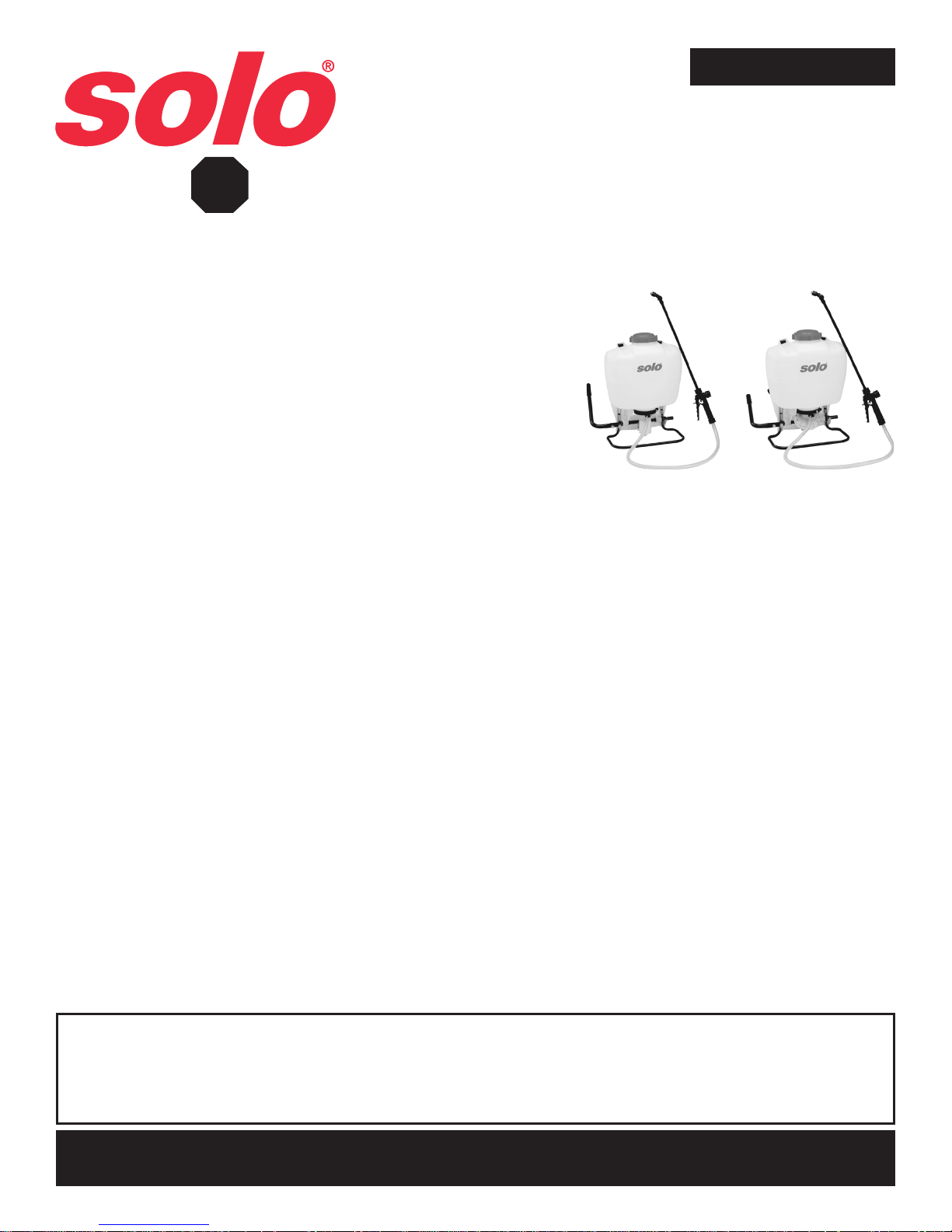
Operator’s Manual & Parts List
425, 425-HD, 425-L, 425-PAF, 475, 475-3N1, 475-PAF, 435, 478, 485,
473-P, 473-D, 473-ECS; includes Deluxe and Heavy Duty Models
STOP!
WARRANTY:
Solo backpack sprayers are covered by Solo’s 1-YEAR LIMITED WARRANTY. Solo manufactured parts which fail due to defective
material or workmanship will be repaired or replaced without charge. See page 5 for full details and complete warranty information.
MAINTENANCE TIP: The cap gasket (#4061345)is prelubricated for
improved sealing. Occasional lubrication with Solo Superior Grease (#9850-P) or
petroleum jelly is recommended.
SAFETY PRECAUTIONS:
1. Before using sprayer with chemicals, fill sprayer with fresh water to assure
that you have it properly assembled; pressurize and practice spraying.
Also, check for any leaks at this time. When thoroughly familiar with the
sprayer operation, follow normal operating procedures.
2. Ensure all pressure in the sprayer is relieved by locking the shut-off
valve in the open position.
3. Avoid contact with chemicals.
4. Always wear rubber gloves, safety goggles and appropriate
protective clothing.
5. Work in a well ventilated area.
6. Individuals should be trained in the proper use of this sprayer, chemical handling procedures, and first aid/emergency
care. Where training is not available, individuals should study and follow the procedures detailed in this manual.
If you are missing parts, instructions or have questions, DO NOT take this unit back to the store. Call
1-800-SOLO-INC (1-800-765-6462). Solo will send the missing parts/information to you promptly.
Piston Diaphragm
WARNING:
Chemicals can be harmful to individuals and the environment if improperly used. In addition, some chemicals are caustic, corrosive or
poisonous and should be avoided. Read warnings and chemical manufacturers’ instructions. Solo high density polyethylene sprayers are
fitted with chemical resistant seals which are compatible to a wide variety of agricultural and household chemicals; however, care should be
exercised to ensure that sprayer components are clean, functioning properly, and in a good state of repair before and during use.
If in doubt about a particular chemical, check with the manufacturer. If you suspect or observe indications that the material may be
unsafe in a Solo sprayer...STOP. DO NOT USE OR APPLY CHEMICAL. ALWAYS WEAR RUBBER GLOVES, GOGGLES, AND
APPROPRIATE PROTECTIVE CLOTHING!
Read and follow operating instructions.
•
Do not fill with, use, or spray flammable materials.
•
Do not modify sprayer.
•
Never spray in the direction of humans, animals or property which might be injured or damaged by spray formula.
•
Do not use disinfectants, solvents or impregnating agents unless first tested to ensure they are not harmful to the
•
environment or sprayer.
Do not use liquids with a temperature above 110°F (43°C).
•
Wear appropriate protective clothing to prevent contact with chemical agents.
•
Rinse and clean sprayer thoroughly after using. Disposal of contaminated rinse should be in accordance with applicable
•
ordinances. Observe the precautionary instructions of the chemical manufacturer.
Do not use any acid (including citrus) or caustic chemicals. For bleach solutions, try our Solo 475-3N1.
•
Remember that a sprayer with liquid is a significant amount of weight (8 lbs. per gallon). Do not climb when wearing
•
the sprayer. Use caution when bending, leaning or walking. Bend at the knees rather than the waist.
During sprayer operation, the pressure cylinder (#4400240) contains compressed air and liquid. Compressed air
•
and liquid under pressure are inherently dangerous. Before making adjustments on sprayers fitted with a pressure
regulating valve assembly (#4800182) located on the pressure cylinder or any other repair or inspection of any
sprayer, be sure to relieve pressure through the shut-off valve and wand.
CUSTOMER SERVICE COMMITMENT FROM SOLO’S SERVICE DEPARTMENT
In the event the sprayer you have purchased has missing or damaged parts, please call 1-800-765-6462, 9:00 AM - 5:00 PM EST.
In order to assist your service representative, please have the following information available: sprayer model number,
part description and part number. A parts list is included in your operator’s manual.
Solo is committed to your satisfaction and is continuing its efforts to earn your future business.
Troubleshooting and parts ordering available on-line.
Visit us on the web at www.solousa.com
Page 2
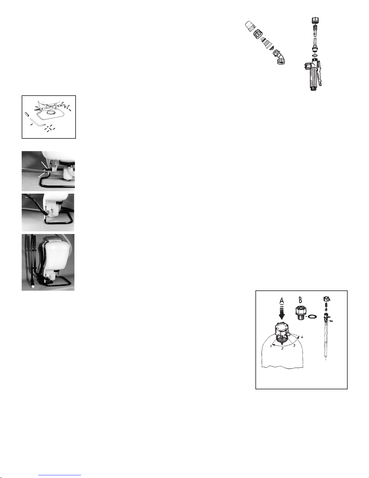
REMOVING PLASTIC ADJUSTABLE NOZZLE
Unscrew the nozzle cap (1) from the nozzle body (3). This is best
accomplished while the retaining nut (2) is fastened tightly to the
elbow (5). Next, unscrew the retaining nut (2). Push the nozzle
body (3) out of the retaining nut (2). The filter with gasket (4) will
come out with the body. To reinstall the nozzle, reverse the above
instructions.
ASSEMBLY INSTRUCTIONS FOR WAND
1. Insert wand into shut-off valve as shown.
2. Tighten the screw cap clockwise onto the shut-off valve.
1. Nozzle
2. Retaining Nut
4. Filter with Gasket
5. Elbow
3. Nozzle Body
O-Ring
Gauge Mount
Shut-Off
Screw Cap
➔
➔
Wand
➔
➔
Install Wand
➔
➔
A
B
PUMP LEVER INSTALLATION: All hardware necessary for pump lever installation is
D
included with the sprayer. The pump lever (C) should be installed as follows: place lever
handle (C) onto the shaft (A). Align bolt holes and install the two bolts (E) and washers (F); then tighten.
To install pump lever on the opposite side on a Diaphragm Pump sprayer, remove the stop plate (D)
C
F
E
F
E
and washer, install the pump lever as above. The stop plate (D) should be mounted on the inner
bolt hole with the closed end of the stop plate pointing downward on the opposite side of the pump
shaft.
FOLD-AWAY PUMP HANDLE* INSTALLATION (FOR DELUXE MODELS ONLY):
Remove bolt and nut from pump handle.
B
A
1.
Slide handle assembly over the pump rod and align the holes so that the rear (elbow) portion
2.
of the handle points up and slightly forward (approximately 45 degrees) and away from the
Solo logo. Reinstall bolt and locknut. Pump handle can be installed on the opposite side of
the sprayer for right hand pumping. (For Diaphragm Pump Sprayer, stop plate will need to be
relocated to the left side.)
The handle can be rotated to either down (pumping) or up (storage) positions. Note: The handle
3.
swings away from the sprayer, then up or down as desired. The spray wand attaches to the
clamps on the handle assembly for storage (does not apply to the brass or stainless steel
wands).
SHOULDER STRAP INSTALLATION:
The top of the shoulder straps are pre-attached to the sprayer by means of a buckle. The lower end
of the straps are attached by fastening the strap hooks to the metal frame between where frame
exits the plastic tank and makes a bend.
REGULATING THE PRESSURE: (FOR DELUXE MODELS ONLY)
The Solo backpack sprayer is equipped with a built-in regulator to control output pressure. This
regulator is operator adjustable. Make adjustments prior to filling tank. To adjust the regulator,
remove the tank cap and the filter basket. Look inside the
spray tank; you will see the top of the regulator. There are 4 fingers on the regulator
knob. The finger farthest to the left is #1; to the right is #4. They are numbered 1, 2,
3, 4. 1 = 15 psi, 2 = 30 psi, 3 = 45 psi, 4 = 60 psi. The higher the pressure, the more
chemical applied from the sprayer in a given amount of time, but the droplets will be
smaller with more drift. If the spray pressure must be changed, excess pressure in
the pressure cylinder must be released back into the tank through the spray tube.
To adjust, push down on the knob and rotate to align the desired number with the
alignment pin. To operate the 425-DELUXE, 475-DELUXE, 485 and 435 at higher
than 60 psi, first release the excess pressure and then replace the adjustment piece
with the optional plug (#4200215).
FILLING:
Mix the spray formula and the proper volume of water in a separate container. Pour
the mix through the filter basket in the tank opening. This keeps debris from entering
sprayer. Note: To fill the sprayer to its full 4 gallon capacity, set the pressure control valve to the 3 or 4 setting. ( DELUXE
MODELS ONLY ) Add 2 or 3 gallons of spray formula mix. Pump the sprayer handle to prime the pump and fill the pressure
cylinder. The volume of liquid in formula mix tank will appear to decrease as the pressure cylinder is filled. Liquid will flow
through the top of the pressure regulator when the cylinder is completely full. Add the remaining formula mix to the tank.
Remember that it’s not necessary to completely fill the sprayer tank each time. Mix only the amount needed to get the job
done.
Setting #1 15 psi
#2 30 psi
#3 45 psi
#4 60 psi
Always read and follow manufacturer’s instructions printed on the product label. This can save money and help prevent
crop and environmental damage.
2
Page 3
OPERATING FEATURES:
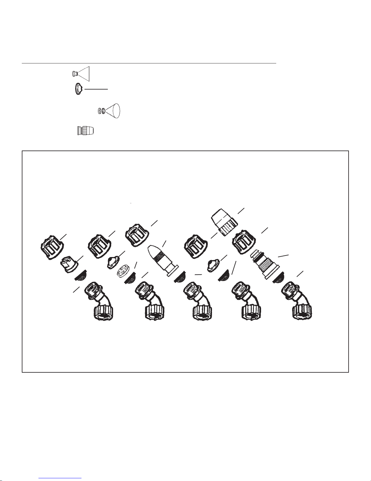
Nozzles - Your Solo sprayer is supplied with nozzle arrangements to provide a variety of spray patterns.
Item Application Part #
Flat spray nozzle Row treatment 4074263
Jet stream nozzle Spot & longer range 4074755
Jet stream nozzle and Shrubs and bushes 4074755
Swirl plate = hollow cone 4074756
Plastic adjustable Spot, shrubs & bushes 4900527
nozzle
SPRAY TIP ASSEMBLY
1. Flat spray nozzle
2. Filter
3. Jet cap
4. Swirl plate
5. Nozzle cap
6. Nozzle body
7. Brass adj. nozzle*
8. Nozzle retaining nut
8
1
8
8
7*
3
4
2
8
2
5
8
3
2
6
2
2
Flat spray Hollow
*Brass adjustable nozzle is not a standard item on all Solo sprayers.
Spray tips should be assembled as above for desired spray pattern.
SPRAYING:
Prime the pump with rapid pump strokes. When you feel very firm resistance, the pressure chamber is filling with
liquid. With repeated piston strokes, the air in the pressure chamber is slowly compressed. In a safe area, point
the wand upward and press the shut-off valve lever spraying for 10 seconds or until no air and only liquid is coming out. This will bleed all of the air out of the hose and wand. By pressing the hand lever, the valve opens, and
liquid is forced through the nozzle. The shut-off valve has a retaining clip which keeps the valve in the “OPEN” position for continuous operation. Pump using the end of the pump handle, as it is less fatiguing. The volume of liquid
delivered varies with the working pressure which should be as high as needed to ensure an adequate spray pattern for
each individual application.
NOTE: Should the pressure drop very quickly, drain the tank completely and pump without liquid. By this procedure, the air
chamber is refilled with the required volume of air. It is advisable to pump the tank completely empty from time to time.
cone spray
3
Brass
adjustable
nozzle*
Jet stream Plastic
adjustable
nozzle
Page 4
WETTABLE POWDERS:
Avoid use in piston pump sprayers models 425, 425-L,
435, 425-PAF, 473-P! The Solo models 475, 475-3N1,
475-PAF, 473-D, 478 and 485 sprayers with a diaphragm
pump are generally resistant to abrasive materials and
are recommended for this purpose. Note: If you use a
wettable powder in your 425, 435, 473-P sprayer, be
sure that it is thoroughly mixed in the formula solution.
Immediately after use, be sure to remove the piston,
clean and lubricate the Viton® collar with Solo Superior
Grease* or petroleum jelly. Thorough flushing of sprayer
will extend the life of its working parts. If you use wettable
powders in the piston pump sprayer, be sure to inspect
regularly for seepage around the piston and repair
accordingly.
CLEANING:
• After spraying, clean the tank thoroughly. If some spray
liquid is left inside, drain tank completely.
• Pumping causes air to be taken in and the remaining
liquid to be discharged. Pump until liquid and air are
coming out through the nozzle.
• Refill tank with a few quarts of clean, soapy water and
pump the water out as explained above (if necessary,
repeat this procedure several times).
• If the shut-off valve is removed, the pump can be
flushed quickly. Improper spray distribution is the result of
a clogged nozzle, which is easily removed and cleaned.
• Soap and water may also be used to clean tank.
• Do not use aggressive cleaning agents or abrasives.
• Follow the recommendations of the chemical
manufacturer for disposal of waste water and
chemicals.
• Activated charcoal in liquid or other form may be used to
absorb chemicals in tanks or spills.
NOTE: When cleaning the sprayer after working with
hormone weedkillers, follow the instructions of the
herbicide producers. Neutralize with activated charcoal.
(Example: add 0.35 oz./1 g. of activated charcoal to 1.7
pint/1 liter of water and leave this detergent in the tank and
the lines approximately for 24 hours.) This is very important
if other chemicals should be sprayed as the residues of the
herbicide may damage susceptible plants. Cleaning after
application of products containing carbolineum, if they
are not water soluble, should be done with a 5% soda lye
having a temperature of 104°F (40°C). Rinse with plenty of
clean water.
MAINTENANCE AND STORAGE TIPS:
To protect the piston, cylinder and Viton® collar, these
parts should be lubricated with Solo Superior Grease* or
petroleum jelly at least once per
season.
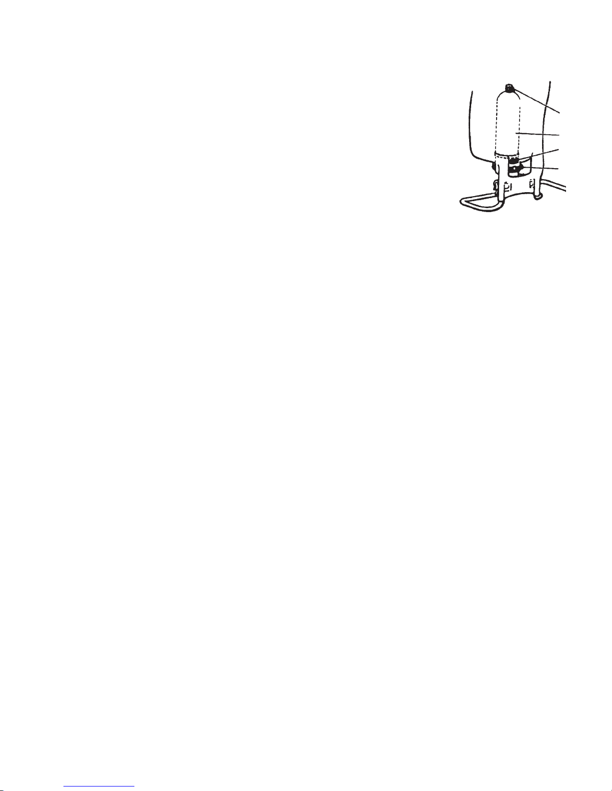
If you find that your sprayer
will not empty the formula tank,
check for a clogged inlet opening (2). The inlet screen is located at the bottom of the pressure
cylinder on the side that faces
your back.
One indication that it needs
cleaning is that when you let
go of the pump handle, it
“springs” to the down position.
The opening can be cleaned
with a small bristle brush or
a discarded toothbrush. See
1. Pressure Cylinder
2. Inlet Opening
3. Cylinder Support
4. Pressure Control Valve
(Deluxe Models Only)
diagram for location of opening.
• After operation, the sprayer should be stored away from
direct sunlight to prevent UV damage.
• After removing the pump or when mounting a new Viton®
collar, treat both the collar and the piston with waterresistant grease.*
• Before winter, drain all liquid in tank, lines and air
chamber. (See “Cleaning.”) Leave shut-off valve locked
in the “open” position.
• For service, visit our website to locate your nearest Solo
dealer. Always insist on original Solo spare parts.
• Regularly inspect hose, wand, pump, tank and shut-off
valve for wear, damage or leaks. Repair promptly.
• Occasionally lubricate cap gasket.*
Avoid excessive wear by:
1) Regular lubrication of Viton® collar, cylinder and piston
with water resistant grease.*
2) Prompt and thorough cleaning and flushing of sprayer.
Soap and water work well.
*Use Solo Superior Grease (#9850-P). Petroleum jelly may also be used.
4
1
2
3
4
Page 5
SOLO LIMITED WARRANTY
Solo Incorporated guarantees the original purchaser of Solo equipment that any failure of Solo manufactured parts due to
defects in material and workmanship occurred during the applicable warranty period will be repaired or replaced without
charge for parts or labor, except for those items not covered by warranty.
CONSUMER LIMITED WARRANTY: Solo equipment purchased for consumer use is covered by this Limited Warranty
for a period of ONE (1) YEAR. Solo’s polyethylene tank is covered by this limited warranty for the life of the unit.
COMMERCIAL LIMITED WARRANTY: Solo equipment purchased for commercial use is covered by this Limited
Warranty for a period of ONE (1) YEAR.
OWNER’S OBLIGATION AND RESPONSIBILITY: Proof of purchase must be provided by the owner in order to obtain
warranty service. Should any failure covered by this Limited Warranty occur, deliver or ship the Solo products or parts to
an authorized Solo service center. Freight, packing and insurance costs, if any, will be borne by the owner. Follow normal
maintenance service to include applicable lubrication, operation and storage of the product as explained in the operator’s
manual.
ITEMS NOT COVERED BY WARRANTY: Provisions of the Limited Warranty will not apply to the following: Any indirect
or consequential damages that may result from the failure or malfunction of the Solo product. Normal service requirements
arising during the warranty period, such as cleaning, normal wear, lubrication, filter, spray tips, etc. Normal service work
over and above the repair or replacement of defective parts. Any failure that results from an accident, customer abuse,
normal wear, neglect or failure to operate the product in accordance with the instructions provided in the operator’s manual
or provided with the product. When an alteration or modification has been performed on a Solo product, Solo is responsible
only for products as originally furnished by Solo, provided the alterations or modifications do not adversely affect the
product’s operation, performance or durability. Parts or accessories that are incompatible with the product are not approved
by Solo.
Full disclosure of Solo’s Limited Warranty is available from your local Solo dealer or SOLO INCORPORATED, 5100
Chestnut Avenue, Newport News, Virginia 23605.
This Limited Warranty gives you specific legal rights and you may also have other rights, which vary from state to state.
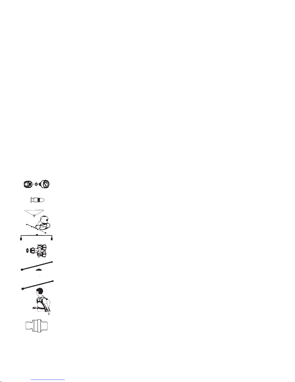
ACCESSORIES:
The following accessories are not standard. Order them from your SOLO dealer.
Pressure control gauge (#49 00 622): Displays spraying pressure so operator can maintain desired
pressure level.
Brass adjustable spray nozzle (#06 10 410-P): Affords operator a full range of sprays from fine to jet
stream. Standard on model 478, 425-PAF and 475-PAF.
Drift guard (#49 00 430): Helps control application of formula under breezy conditions.
4-nozzle spray boom and mounting hardware (#49 00 298): Mounted on the back part of the sprayer frame
with 4 hollow cone jets for area treatment (total width 49-3/4”; distance between nozzles 16”).
2-nozzle spray boom (#49 00 514): Handheld spray boom mounts on end of spray wand (total width 33”;
distance between nozzles 24”). Includes 2 flat spray nozzles.
Twin nozzle (#49 00 477): This is a multi-purpose nozzle that attaches to the end of the spray wand
for double row application.
4' to 8' Carbon Fiber Wand (49 00 445) This lightweight spray wand adjusts from 4' to 8' and replaces
the standard spray tube to reach eaves or trees up to 25 ft. (7.6 meters) .
60" Brass spray wand (#49 00 528): The spray wand is 60” (150 cm) long and replaces the standard
spray tube for treating trees up to heights of 16 ft. (5 meters). Additional extension tube available in
20” length (#49 00 513).
Deluxe Shoulder Saver Harness (#43 00 343): Heavy duty, fully adjustable, padded shoulder straps,
large, padded lumbar support and fully adjustable chest strap.
Solo Superior Grease (#9850-P): (4 oz.) Used in the manufacture of all Solo parts.
Controlled Flow Valve (CFValve™): Provides constant pressure and flow to the spray nozzle and can
be used in various applications.
In the best interest of continued technological progress, we reserve the right to change design and configuration of any
product without prior or other notice. Therefore, please note that text and illustrations of this manual are not to be considered
binding and do not constitute a basis for legal or other claims.
NOTE: An order form is provided on pages 11 and 12.
5
Page 6
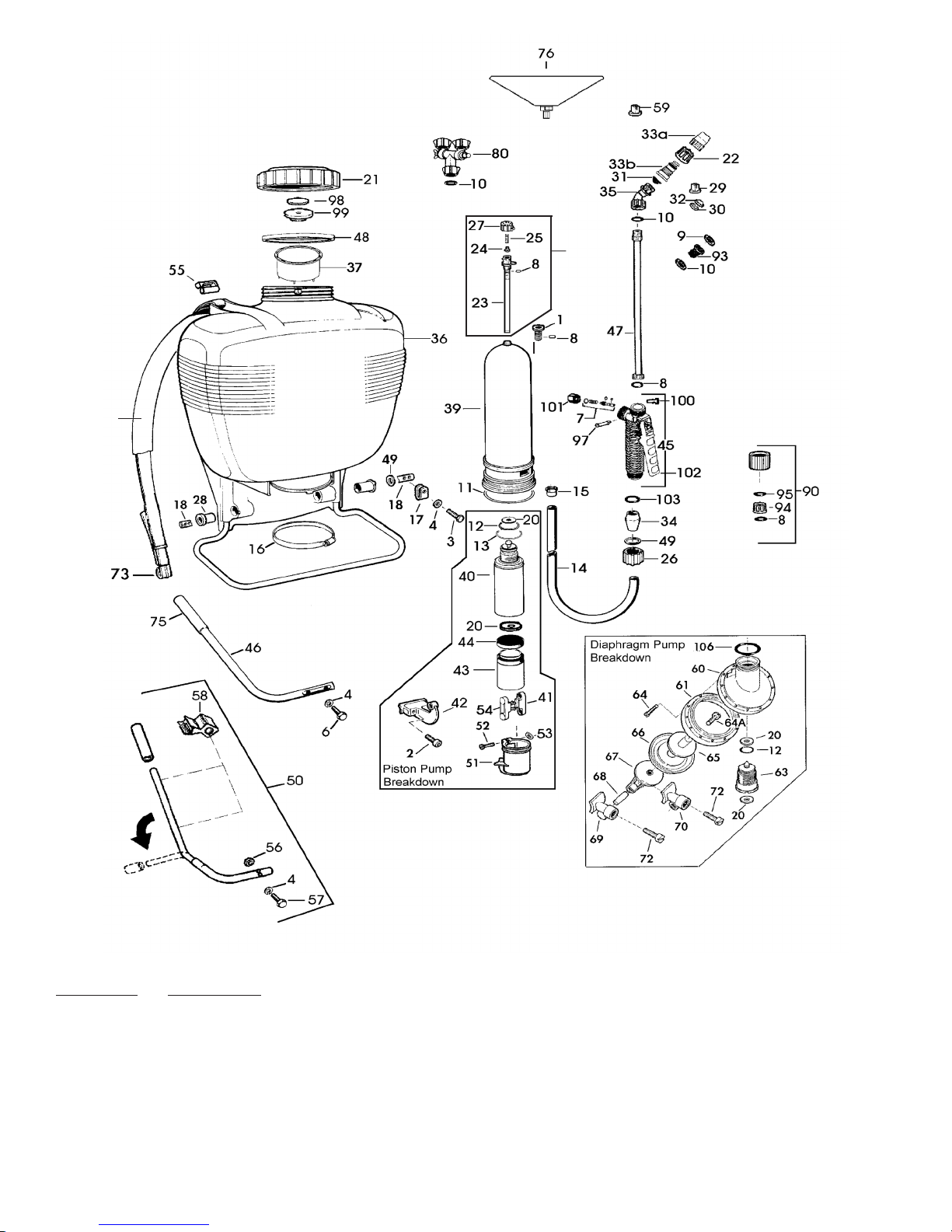
SPARE PARTS LIST
Liste de pièces de rechange
Lista de piezas de recambio
38
Deluxe models only
107
DLX
Only
*Not standard on all models.
SPECIAL PARTS AND ACCESSORIES (Not shown in parts list)
Order No. Description
4900310N Conversion kit (from piston to diaphragm pump)
0610406-K Diaphragm pump repair kit includes 8, 11, 12, 20 (2 ea.), 24, 25, 66, 106
0610407-K Piston repair kit includes 10-13, 20 (2 ea.), 24, 25, 44
0610411-K Wand repair kit includes 7, 8, 10, 22, 26, 34, 49, 103
0610409-K Piston, rod & collar kit includes 41-44, 54
4400203 Pump assembly (Piston) includes 1, 8, 11, 12, 13, 20 (2 ea.), 39, 40, 41, 42, 43, 44, 54, 107
4400221 Pump assembly (Diaphragm) includes 1, 8, 11, 12, 20 (2 ea.), 39, 61, 63, 64 (13 ea.), 65, 66,
67, 106, 107
6
Page 7
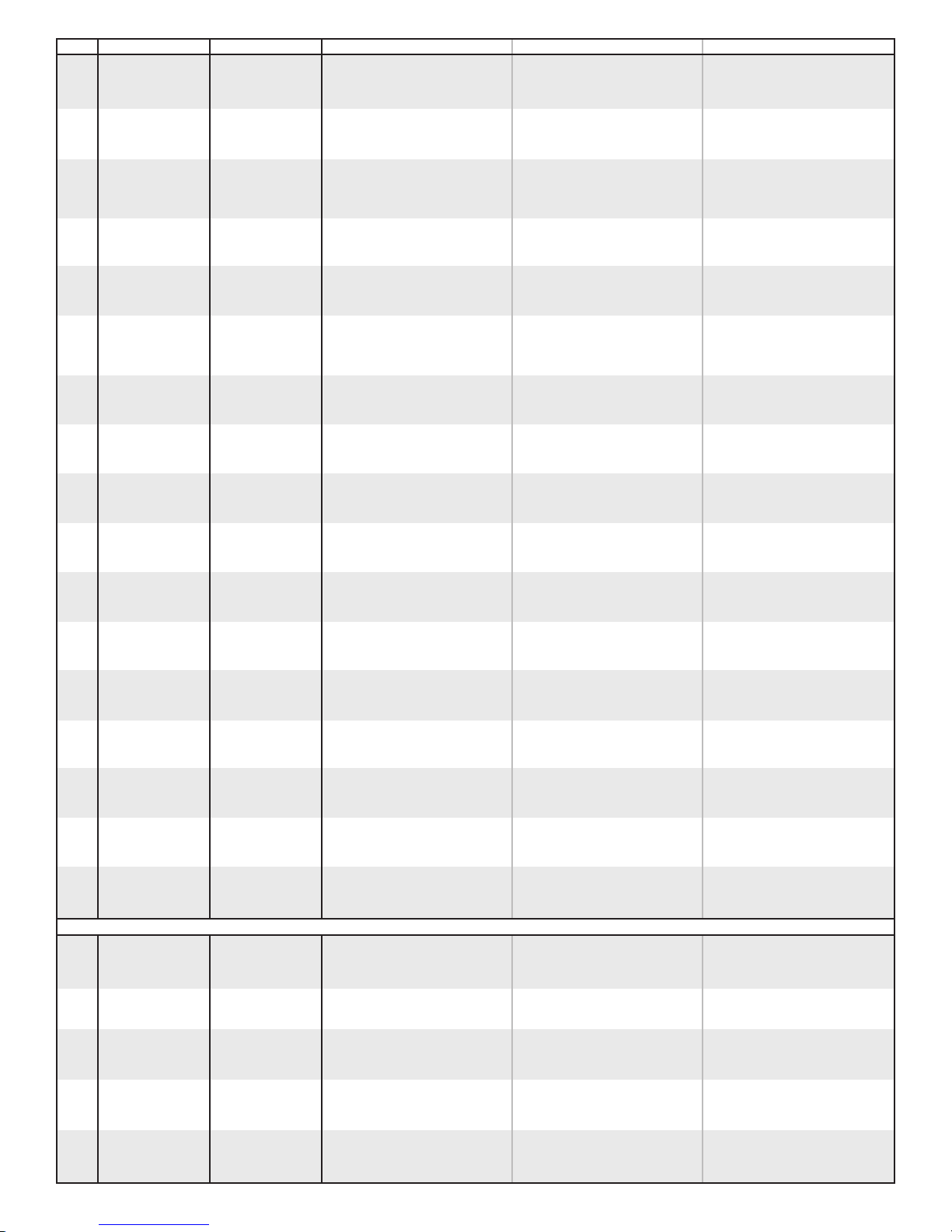
POS. # ORDE R # FOR M OD . DESCR IP TION FRANC AI S ESPA ÑO L
2 00 10 165 Bolt Vis T.C. Tornillo cil.
3 00 12 185 Bolt ** Vis T.C. Tornillo cil.
4 00 30 131 Washer ** Rondelle Arandela
6 00 12 185 Bolt Vis T.C. Tornillo cil.
8 00 62 258 Gasket Joint de connection Junta de conexion
10 00 62 115 O-ring Joint bague Anillo O
11 00 62 291 O-ring Joint bague Anillo R
12 00 62 139 O-ring Joint bague Anillo R
13 00 62 140 O-ring Joint bague Anillo R
14 00 64 234 Hose 48” (item 26, 34, 49, 103 incl.) Tuyau (Pos. 26, 34, 49, 103 incl.) Manguera (articulo 26, 34, 49, 103 incl.)
15 00 66 388 Hose clamp Collier cpl. Abrazadera
16 00 66 394 Clamp Collier cpl. Abrazadera
17 40 43 123 Stop plate ** Butêe Pieza de apoyo
18 40 35 111 Pump shaft Tuyau Tubo
20 40 61 257 Valve plate Joint de soupape Place de valvula
21 42 00 242 Red tank cap (item 48, 98 & 99 incl.) Couvercle Tapa del depôsito (roja)
— 42 00 305 Heavy Duty Black tank cap (item 48, 98 & 99 incl.) Couvercle Tapa del depôsito (negra)
22 40 74 148 Retaining nut Ecrou de raccord Tuerca de manguito
23 40 74 323 Valve body Pièce de règlage Pieze de ajuste
24 40 74 350 Sealing piece Joint Junta
25 00 70 260 Compression spring Ressort de compréssion Resorte de presion
26 40 74 337 Retaining nut Ecrou de raccord Tuerca de manguito
27 40 74 344 Control knob Pièce de règlage Tapa de ajuste
28 40 74 410 Bushing Coussinet Cohinete
29 40 74 263 Flat spray jet Buse à diffusion large Tobera de chorro ancho
30 40 74 756 Swirl plate Pièce girafoire Pieze de rayado
31 40 74 283 Jet filter tamis de gicleur Piltro de tobera
32 40 74 755 Jet cap Capuchon de gicleur Tapa de tobera
33 49 00 527 Plastic adjustable nozzle (Inc. a & b) Buse réglable en plastique Boquilla ajustable
34 40 74 500 Clamp Pièce de serrage Pieze de retencion
35 40 74 527 Elbow Coude Code
36 42 00 162 425, 474, 475, 476 Tank and frame assy., 4 gal. Support de rèservoir, 151 Soporte de depôsito, 151
42 00 293 435,485 Tank and frame assy., 5 gal. Support de rèservoir, 201 Soporte de depôsito, 201
40 71 305 473P, 473D Tank and frame assy., 3 gal. Entonnoir Embudo Filtro
37 42 00 166 Filter basket Le panier-filtre Filtro de canasta
38 43 00 315 Shoulder strap (item 73 incl.) Bretelle (Pos. 73 incl.) Correaje (articulo 73 incl.)
38 43 00 340 Deluxe Models Deluxe Shoulder Strap (Item 73 incl.) Bretelle de luxe (Pos. 73 incl.) Correaje de lujo (articulo 73 incl.)
39 44 00 240 Pressure cylinder (Deluxe Models) Cylindre cpl. Cilindro mont
4400240N Pressure cylinder
40 40 73 190 Cylinder, assy. (item 12, 13, 20 incl.) Bielle sand tèton Biela
41 40 74 409 Connecting rod without stud Levier Palanca
42 40 74 262 Lever Piston Piston
43 40 73 558 Piston Manchette Viton Manguito Viton
44 44 00 189 Viton® collar Robinet d’arrêt Grifo de cierre, mont.
45 48 00 170 Shut-off valve, assy. Levier de pompe (pos. 75 incl.) Palanca de bomba (articulo 75 incl.)
46 48 00 17325 Pump lever (item 75 incl.) Tuyau pulvèrisateur (500 mm) Tubo atomizador (500 mm)
47 49 00 230 Spray tube 20” (item 8, 26 incl.) Joint bague (pos. 8, 26 incl.) Anilio de junta (articulo 8, 26 included)
49 00 645 Stainless Wand
4900421 Brass Wand
48 40 61 345 Gasket Rondelle Arandela
49 00 31 356 Washer Coiffe protectrice Tapa protectora
51 40 74 680 Protective cover vis T.C. Tronillo cil.
52 00 10 110 Bolt Ecrou. hex. Tuerca hex.
53 00 20 101 Hex. nut Bielle avec teton Biela
54 40 74 408 Connecting rod with stud Porte-bretelle Hebilla para correa
55 40 74 412 Buckle Carter de membrame Carter membrana
58 40 74 996 Wand retainer clip Retenue de la lance
60 40 73 411 Housing (diaphragm) Joint bague Anillo O
61 40 73 410 Flange Siège soupape (pos. 12, 20 incl.) Pieza rosada (articulo 12, 20 incl.)
63 44 00 222 Valve, assy. (item 12, 20 incl.) Vis T.C. Tornillo cil.
64 00 18 275 Screw Plaque à membrane Chapa de membrana
64A 00 18 427 Diaphragm screw Vis de diaphragme Tornillo de la diafragma
65 40 74 256 Plunger Membrane Membrana
66 40 74 245 Diaphragm Bielle Biela
66 40 74 246 475-3N1 Model Only Diaphragm Bielle Biela
67 40 74 255 Lever Goujon Perno
68 40 31 130 Wrist pin Levier 1 Palanca 1
69 40 74 234 “R” connecting bracket Levier 2 Palanca 2
70 40 74 243 “L” connecting bracket Vis T.C. Tornillo cil.
72 00 10 141 Bolt Accroche Gancho
73 40 74 835 Hook Crochet Gancho
75 40 74 392 Grip Poignée Apretón
97 40 74 295 Pin Goupille Perno
98 40 61 464 Vent plate Plaque de décompression Placa de la respiradora
99 40 74 123 Vent cap Capuchon de décompression Tapa de la respiradora
100 40 74 329 Lock clip Pince de verrouillage Sujetador de cerradura
101 40 74 336 Retaining nut Écrou de serrage Tuerca de retención
102 40 74 335 Lever Levier Palanca
103 00 62 271 O-ring Joint torique Anillo-O
106 00 62 324 O-ring Joint torique Anillo-O
107 48 00 182 Pressure Control Valve Régulateur de Pression Valvula de Control
** ** Diaphragm Pump Sprayer Only
49 00 207 Brass
Adj. spray nozzle Bouchier
Boquilla ajustable
ACCESSORIES
1 42 00 215
7 06 10 402-K Shut-off valve repair kit Pochette robinet d’arrét Juego rep. grifo de cierre\
49 00 319
26 incl.)
50 49 00 454
56 00 20 119
57 00 12 192
58 40 74 996
59 00 65 210
76 49 00 430
80 49 00 477
— 49 00 528
90 49 00 622
— 49 00 513
93 27 00 316
94 40 74 338
95 00 62 249
— 06 10 410-P Brass
— 43 00 343 Deluxe
— 42 00 205
— 49 00 258N
incl.)
4800182 Pressure Regulating Valve (Items 8,23,24,25,27) Soupape de regulation de la pression Valula reguladora de pression
Heavy Duty
Deluxe Models Only
Heavy Duty
Plug (item 8 incl.) Bouchon (pos. 8 incl.) Tapón (articulo 8 incl.)
Spray wand 27” (690 mm) (item 8, 26 incl.) Lance de vaporisation de 69 cm (27 po) i8, 26 incl.) Vara de pulverizador 27" (690mm) (art. 8
Fold-away handle (item 4, 56, 57, 58 incl.) Poignée rabattable (réf. 4, 56, 57, 58 compr.) Manilla pliegue (articulo 4, 56, 57, 58 incl.)
Nut Écrou Tuerca
Bolt Boulon Cerrojo
Clip Pince Sujetador
Brass flat spray nozzle Buse à jet plat en laiton Boquilla de pulverizador de latón plano
Drift guard Anti-dèrive Protector de la deriva
Double spray nozzle Buse à double jet Boquilla doble de pulverizador
Extension wand 60” (1250 mm) Rallonge de lance de 1,25m (60 po) Vara de extensión (1250 mm)
Pressure gauge w/connection parts Mandometro
Extension tube 20” (500 mm) Clapet anti-retour Tuba alargador (500 mm)
No drip check valve Valvula de retencion
Retaining nut Tuerca de manguito
O-ring
Adj. spray nozzle assy. Joit bague Tobera de allura, mont.
Shoulder saver harness Buse longue protee, cpl.
Reduction insert, gaskets incl. Reduceur avec jints Empaquetaduras
Elbow nozzle assy. (item 10, 22, 31, 33, 35 incl.) Pochette joints (10, 22, 31, 33, 35 incl.) Juego empaquetaduras8 (10, 22, 31, 33, 35
Joint torique
Anillo O
7
Page 8
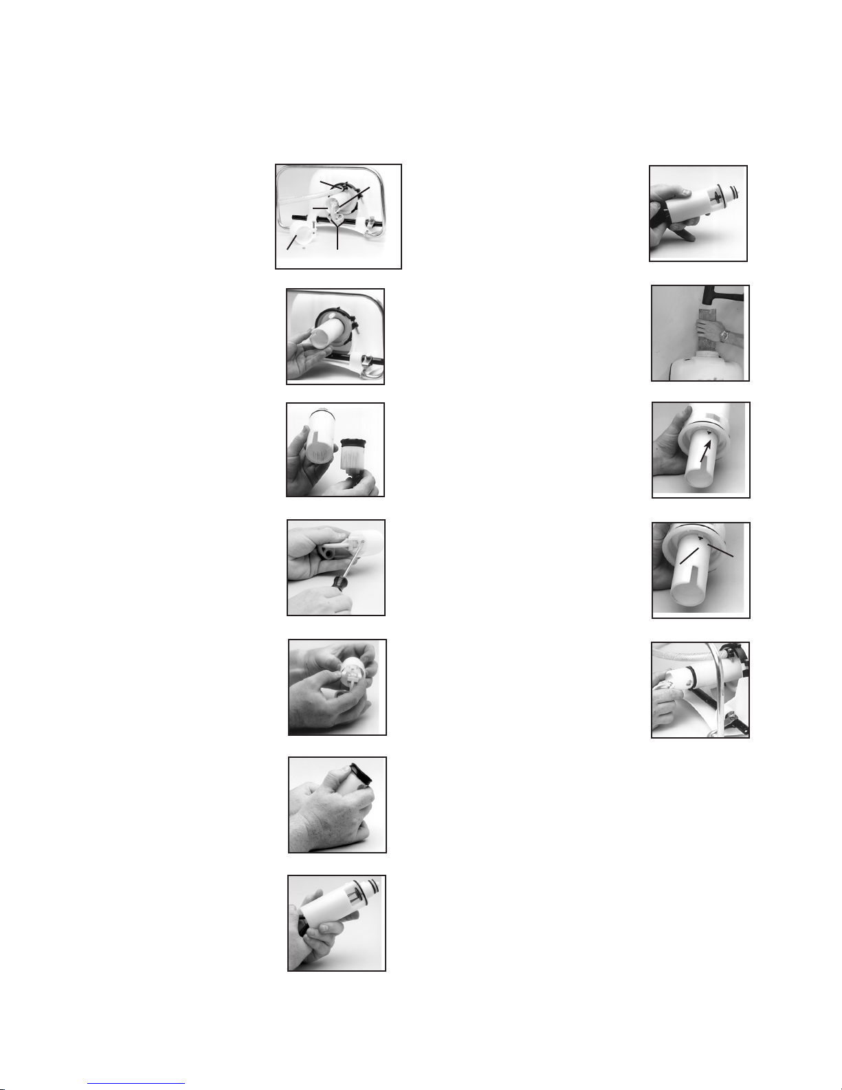
INSTALLATION INSTRUCTIONS
PISTON PUMP REPAIR KIT ( # 0610407-K)
Tools needed for kit installation: 6mm Allen Head Wrench, Flat Screwdriver, 11mm Wrench or Cresent Wrench, Long Nose Pli-
ers, Hammer, 13mm Socket or Wrench, T-25 Torx Screwdriver, Grease or Petroleum Jelly, 2X4 Piece of wood 18” long
1. Using a 13mm socket wrench
remove the handle bolts, and set
aside. Lay unit on its back with
pump assembly facing you. See
figure 1. Loosen hose clamp (E).
Pull off sprayer hose. Caution:
There may be liquid inside the
hose and pressure cylinder even
when the tank is empty. Wear
protective gloves. Next, remove
the nut and bolt from protective
cap, and remove cap (C). Rotate
the pump shaft to access the two
lever bolts in the center (B). Using
a 6mm allen head wrench, remove
them. Pull the piston (F) out of the
piston cylinder (D).
2. To remove the piston cylinder
assembly, turn the cylinder counter
clockwise when viewing from the
bottom. Figure 2. Caution: The
piston cylinder has sharp edges.
3. Check the inside of the piston
and cylinder for scratches. If the
piston or cylinder are scratched,
replace. Figure 3.
4. To remove connecting rods from
the piston and lever, insert a flat
tip screwdriver between the two
connecting rods and twist. Figure 4.
5. With the new piston, place the
two connecting rods over the studs
on the inside of the piston. Place
the lever studs into the connecting
rods and snap together with your
fingers. Figure 5.
6. To replace the Viton® collar,
push it off the top of the piston with
your thumb. Figure 6. Install the
new collar on the piston onto the
form fitted sides.
C
E
D
Figure 1.
Figure 2.
Figure 3.
Figure 4.
Figure 5.
B
plate. Figure 7. Install a new valve
F
plate and firmly reseat the retaining
pin using needle nose pliers. Figure 8.
8. If necessary remove the
pressure cylinder by unscrewing
the pressure regulator control, if
equipped. Remove the large clamp
Figure 8.
at the bottom of the cylinder. Use a
block of wood and hit forcefully with
a hammer, driving the assembly
through the bottom of the tank.
Figure 9.
9. Next, assemble the piston
cylinder. First grease the O-ring on
Figure 9.
the piston cylinder, being careful
not to get any on the valve plate,
and then place the piston cylinder
into the pressure cylinder. Screw
the piston cylinder clockwise until
it is tight and the bottom O-ring is
no longer seen. Figure 10. When
properly seated the notch on the
Figure 10.
piston cylinder (G) will line up with
the indent on the pressure cylinder
(H). Figure 11.
H
10. Apply a light coat of grease to
the inside of the piston cylinder wall
and on the Viton® collar, and then
re-install the piston into the piston
cylinder. Figure 12. To insert the
piston, tilt at a slight angle with
the leading edge of the Viton®
collar placed over the slot. When
seated, install the 6mm Allen Head
bolts through lever base into shaft.
Replace the protective cap and
tighten the nut and bolt. Reinstall
the handle. Replace the hose and
black hose clamp making sure it is
firmly secured.
G
Figure 11.
Figure 12.
7. Remove the valve plate and
O-rings from the outside of the
piston cylinder. Install the new
valve plate and the two O-rings
making sure the O-rings seat in the
grooves. Finally, inside the piston
cylinder you will find a second
valve plate. Using needle nose
pliers, pull out the red or orange
pin and remove the valve
Figure 6.
Figure 7.
Note: Always wear rubber gloves, safety goggles and appropriate
protective clothing when repairing a sprayer. Work in a wellventilated area. Prior to repair, flush unit with water by filling,
then spraying the water into an appropriate container or area.
Ensure that all pressure is released by locking the shut-off valve
in the open position. Once a repair is completed, fill the unit with
clean water, pressurize, and check for leaks. If the sprayer leaks,
DO NOT USE. Repair leaks and recheck.
8
Page 9

INSTALLATION INSTRUCTIONS
Diaphragm Pump Repair Kit ( # 0610406-K)
Tools needed for kit installation: 6mm Allen Head Wrench, Flat Screwdriver, 11mm Wrench or Cresent Wrench, Long Nose Pli-
ers, Hammer, 13mm Socket or Wrench, T-25 Torx Screwdriver, Grease or Petroleum Jelly, 2X4 Piece of wood 18” long
1. Using a 13mm socket wrench,
remove handle bolts and loosen the
stop plate (A) and remove the two
allen head screws (B) that hold the
connecting pieces to the pump rod.
Figure 1.
2. With unit laying on its back with
pump assembly facing you, remove
the pump rod (C). Loosen hose
clamp and remove pressure hose
(D). Next, loosen the clamp at the
base of the sprayer (E). Figure 2.
3. Push the pressure cylinder
approximately 1" out of the bottom
of the tank. Then turn the pump
assy. 180 degrees. Note: Wooden
block may be used to tap the pump
assembly through bottom of tank.
Remove pressure regulating valve,
if equipped before removal of
cylinder.
4. Next remove the 12 torx screws
that hold the flange in place. The
flange and diaphragm can then
be removed. Figure 3. Note: For
clarity the pressure cylinder is
shown removed from the tank.
5. To replace the diaphragm,
remove the connecting rod retaining
screw (G) from the plunger and
lever (F). Replace the diaphragm
and reassemble. See Figure 4.
Figure 1.
Figure 2.
Figure 3.
G
Figure 4.
9. When reassembling the pump
housing to the pressure cylinder, be
sure the square tab on the pump
housing (K) is aligned in the notch.
See arrows (L) on the pressure
cylinder in Figure 8. Be careful not to
pinch or nick the O-ring.
Note: Grease O-rings for re-assembly.
Screw the valve assembly into the
cylinder.
10. Place diaphragm assembly (O)
onto the pump housing (M). Place
the flange (N) over the diaphragm.
Reinstall the 12 torx screws around
the outside diameter of the flange.
Figure 9.
11. Push pressure cylinder into the
tank being careful not to pinch the
large O-ring (P).
Note: Wooden block may also be
used for installation of the pressure
cylinder.
F
12. Tighten pump clamp securely
(E). Install pump rod (C). Reinstall
the connecting pieces and allen
head screws (B). Reinstall the stop
plate (A) making sure that the bolt
goes through the rear hole. Reinstall
H
the hose and hose clamp making
sure it is firmly secured (D).
K
Figure 8.
M
N
Figure 9.
Figure 10.
Figure 11.
L
O
P
6. The valve assy. (H) is removed
using a locally made tool. Remove
red valve plate retaining pin using
needle nose pliers, then insert tool
into slots. See Figure 5. Use a
screwdriver to rotate tool counter
clockwise.
7. Once the valve assembly is
removed, the valve plates and
O-rings can be replaced. The
bottom valve plate is secured into
place with a red retaining pin. Push
pin into place using needle nose
pliers. Figure 6.
8. The pump housing (I) is
separated from the pressure
cylinder (J) by pulling it off.
Figure 7. The O-ring can then be
replaced.
Figure 5.
Figure 6.
J
Figure 7.
I
Note: Always wear rubber gloves, safety goggles and
appropriate protective clothing when repairing a sprayer. Work
in a well ventilated area. Prior to repair, flush unit with water by
filling, then spraying the water into an appropriate container or
area. Ensure that all pressure is released by locking the shut-off
valve in the open position. Once a repair is completed, fill the
unit with clean water, pressurize, and check for leaks. If the
sprayer leaks, DO NOT USE. Repair leaks and recheck.
9
Page 10

10
Page 11
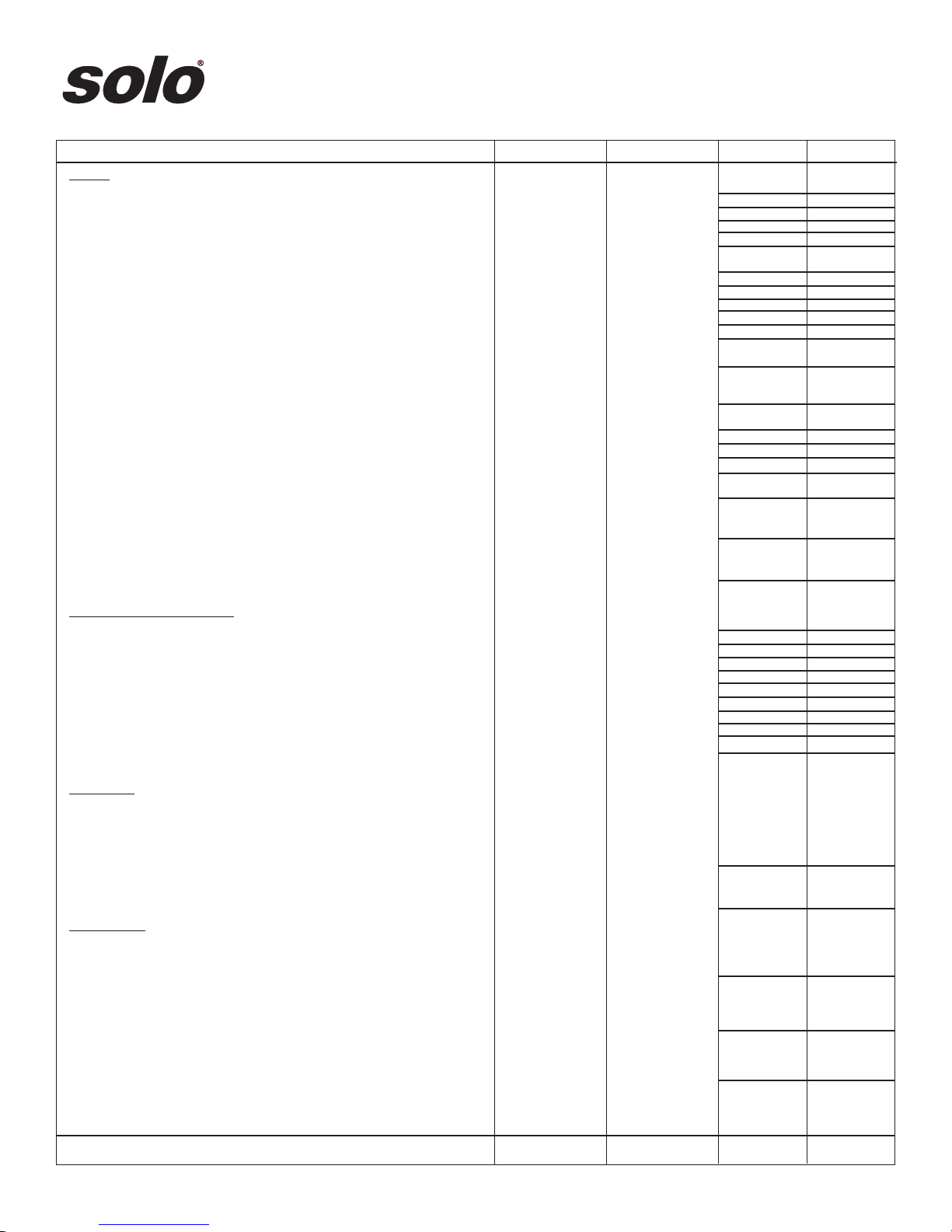
ORDER FORM
Order parts and accessories online at www.solousa.com or from your Solo dealer. If there is no local Solo dealer, use this form to order
Item Names/Description Part No. Retail Price Qty. Total
Nozzles
Flat spray nozzle - surface area & row treatment 40 74 263 2.00
Jet cap 40 74 755 1.50
Swirl plate 40 74 756 1.50
Filter - standard 40 74 283 2.55
Sprayer elbow and nozzle assortment 06 10 408-P 14.95
No-drift wide angle flat nozzles - .60 GPM 40 74 513 2.50
mainly for spraying herbicides at low pressure. .30 GPM 40 74 514 2.50
At 15 psi they deliver: .24 GPM 40 74 386 2.50
.12 GPM 40 74 385 2.50
Elbow nozzle assembly 49 00 258N 6.35
Double spray nozzle - for double row application 49 00 477 29.95
spraying in two directions simultaneously.
Brass adjustable spray nozzle kit - with jet filter and screw 06 10 410-P 8.75
cap for tree spraying (from fine misting to a jet stream).
Brass adjustable spray nozzle (same nozzle as kit above) 49 00 207 6.25
Plastic adjustable nozzle 49 00 527 4.25
Hollow cone nozzles - for shrubs & bushes: 1.4 mm 49 00 252 2.85
1.8 mm 49 00 322 2.85
Foam spray nozzle - for low drift & water saving 49 00 397 14.95
application of herbicides which tend to foam.
No drip check valve - prevents spray tip from leaking 27 00 316 4.95
when not in use.
Nozzle assortment - includes flat, hollow cone, no drift, 06 10 456-P 12.95
and plastic adjustable nozzles.
Extension tubes and spray wands
20” spray wand 49 00 230 9.95
20” extension tube 49 00 513 16.95
21” stainless steel wand 49 00 645-P 11.95
20” brass spray wand 49 00 421 12.95
27” spray wand 49 00 319 13.95
40” brass telescoping wand 49 00 478 34.95
48” carbon fiber wand 49 00 449 39.95
60” brass spray wand 49 00 528 34.95
4’ to 8’ Carbon Fiber Wand 49 00 445 79.95
Note: extension tubes attach to wands to extend length.
Spray wands attach to shut-off valve only.
Spray booms
Spray booms - spray 2 or 4 rows at once with:
2-nozzle spray boom - handheld (total width 33”) 49 00 514 34.95
distance between nozzles 24”. Includes 2 flat spray nozzles.
4-nozzle spray boom - mounts on rear of sprayer 49 00 298 99.90
(total width 49 3/4”; distance between nozzles 16”).
Includes 4 hollow cone nozzles.
Specialty items
Shoulder Saver Harness - padded shoulder straps and 43 00 343 29.95
padded lumbar support reduces lower back fatigue.
Fits all models.
Pressure gauge kits - indicates spray pressure. 49 00 622 29.95
Use with shut-off valve 4800170. Fits all models.
Drift guard - complete control for herbicide applications in 49 00 430 16.95
berry, flower, vegetable, cotton & other applications.
SUBTOTAL
Prices and technical specifications are subject to change without notice.
11
Page 12
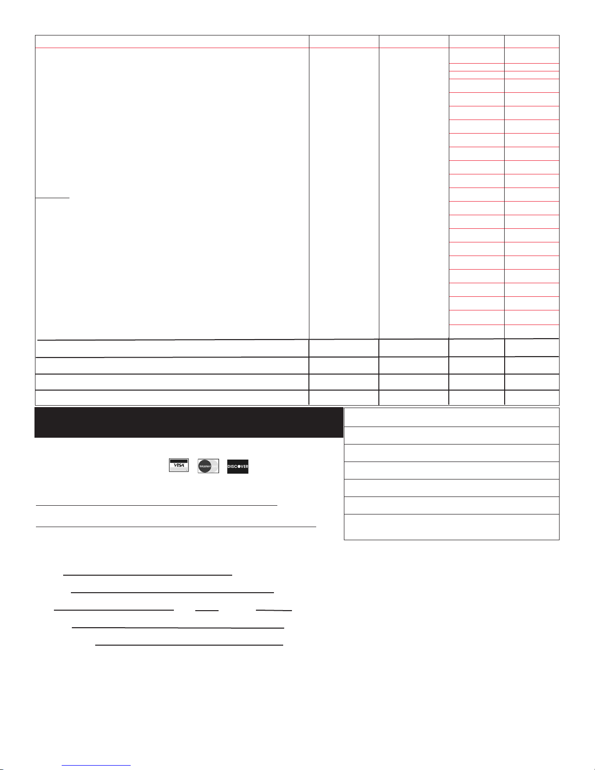
Item Names/Description Part No. Retail Price Qty. Total
Pro spot drift guard. Controls spray to a 3” spot 49 00 626 5.95
Tank cap w/valve assembly 42 00 242 4.95
Filter basket 42 00 166 5.95
Hose - 48” long (120 psi) 00 64 234 5.95
Shut-off valve 48 00 170 15.95
Shut-off valve, spray wand & nozzle elbow assy. 49 00 170N 19.95
Pressure cylinder 44 00 240 19.95
Fold away pump handle 49 00 454 12.50
Complete piston pump assy w/pressure control valve 44 00 203-P 29.95
Complete diaphragm pump assy w/pressure control valve 44 00 221-P 29.95
Repair kits
Shut-off valve repair kit 06 10 402-K 6.50
Diaphragm pump repair kit 06 10 406-K 14.95
Piston pump repair kit 06 10 407-K 19.95
Shut-off valve and wand repair kit 06 10 411-K 9.95
Piston, rod and collar kit 06 10 409-K 19.95
Conversion kit (from piston pump to diaphragm pump) 49 00 310N 26.50
Plug - to operate at higher than 60 psi (DELUXE MODELS SEE PAGE 2) 42 00 215 5.95
Solo Superior Grease - (4oz.) used in the manufacture of all Solo Parts 9850-P 2.95
Sprayer service DVD - explains how to repair the backpack and handheld 998SPDVD 9.95
sprayers in non-technical language.
Mail or Fax to: Solo • 5100 Chestnut Avenue
Newport News, VA 23605 • Phone: (757) 245-4228 • Fax: (757) 245-0800
Order Online: www.solousa.com E-mail: [email protected]
Please do not send cash with this order. Make check or money order payable to Solo Incorporated. You may request C.O.D. shipment. Please call for current C.O.D. charges.
Form of Payment:
Credit Card
Check or Money Order
C.O.D.
/ / / / / / / / / / / / / / / /
Credit Card Number
/ / / /
Expiration Date Signature
We cannot process your credit card purchase without a signature and expiration date.
Name:
Address:
City: State Zip Code
Phone #:
Email Address:
Total from page 11 $
Total from page 12 $
Total $
VA, NC, WA residents add applicable sales tax
$
SHIPPING CHARGE $ 7.95
Grand Total $
Please allow 1-2 weeks for delivery
12
 Loading...