

Page 1
User
Manual
www.solo-tester.com
Page 2
Warning
This product is intended to be used at height.
Exercise great care and always wear appropriate PPE (personal protective equipment) when operating above head height in
order to avoid the risk of injury.
DO NOT OVER REACH. Keep proper footing and balance at all times. Proper footing and balance enables better control
of the equipment in unexpected situations.
Pay particular attention to avoid contact with overhead items such as light ttings, overhead power cables and any other
objects that could be accidentally dislodged which might cause danger to the operator or anyone else in the vicinity.
Avoid prolonged, direct exposure to the vapour generated by Solo 365. Safety Data Sheets for the Solo 370 battery pack and
Solo ES3 Smoke Cartridge are available. It is recommended to review the safety data sheets for Solo 370 Battery Pack and
Solo ES3 Smoke Cartridge before use (see www.detectortesters.com).
Warning
This product contains hot parts.
DO NOT TOUCH the heat element. It may be very hot immediately after use and may burn if touched.
Caution
Contains Lithium Ion rechargeable batteries:
• Do not dismantle, open, shred or incinerate batteries.
• Do not expose batteries to heat or re. Avoid storage in direct sunlight.
• Do not short-circuit a battery. Do not store batteries loose in a box or drawer where they may short-circuit each other
or be short-circuited by other metal objects.
• Do not subject batteries to mechanical shock.
• Keep batteries clean and dry.
• Do not use any charger other than that specically provided for use with the equipment. Refer to the manufacturer’s
instructions or equipment manual for proper charging instructions.
• Do not leave a battery on prolonged charge when not in use.
• Do not use any battery which is not designed for use with this equipment.
• Do not use the battery in any other application.
• Keep batteries out of the reach of children.
• Dispose of properly.
Warning
Contains precision parts which may be easily damaged and cause injury. DO NOT TOUCH the smoke uid intake pipe in
the smoke cartridge area.
Important
Information
• Read this User Manual completely before using your
Solo 365.
• Keep this User Manual - Save all safety and operational
instructions for future reference.
• Take note of the Warnings - Read carefully and follow
all warning labels on the product and those described
in this User Manual.
• Solo 365 is electronic test equipment and care should
be taken when handling and storing. Dropping the
unit on to a hard surface could damage it. Please look
after it, treat it with care for lasting use.
• This product is designed for indoor use only and
should not be subject to harsh environments. It is not
designed for use in hazardous areas (those containing
explosive vapour or dust). Do not use the equipment
in places where temperatures and/or humidity are
high or go through rapid changes including:
- Direct sunlight
- Near heat sources (stoves, radiators, etc.)
- Sandy or dusty environments
- In the presence of strong magnetic elds
- Places prone to strong vibration
- Restrictions detailed in the Technical
Information (see Section 9.2).
• Do not use your Solo 365 if it is not operating
correctly (see fault nding guides) and consult
Troubleshooting (Section 8) of this manual. If required
seek technical advice (Section 9).
• If the equipment is used in a manner not specied
by the manufacturer, the protection provided by the
equipment may be impaired and warranty invalidated.
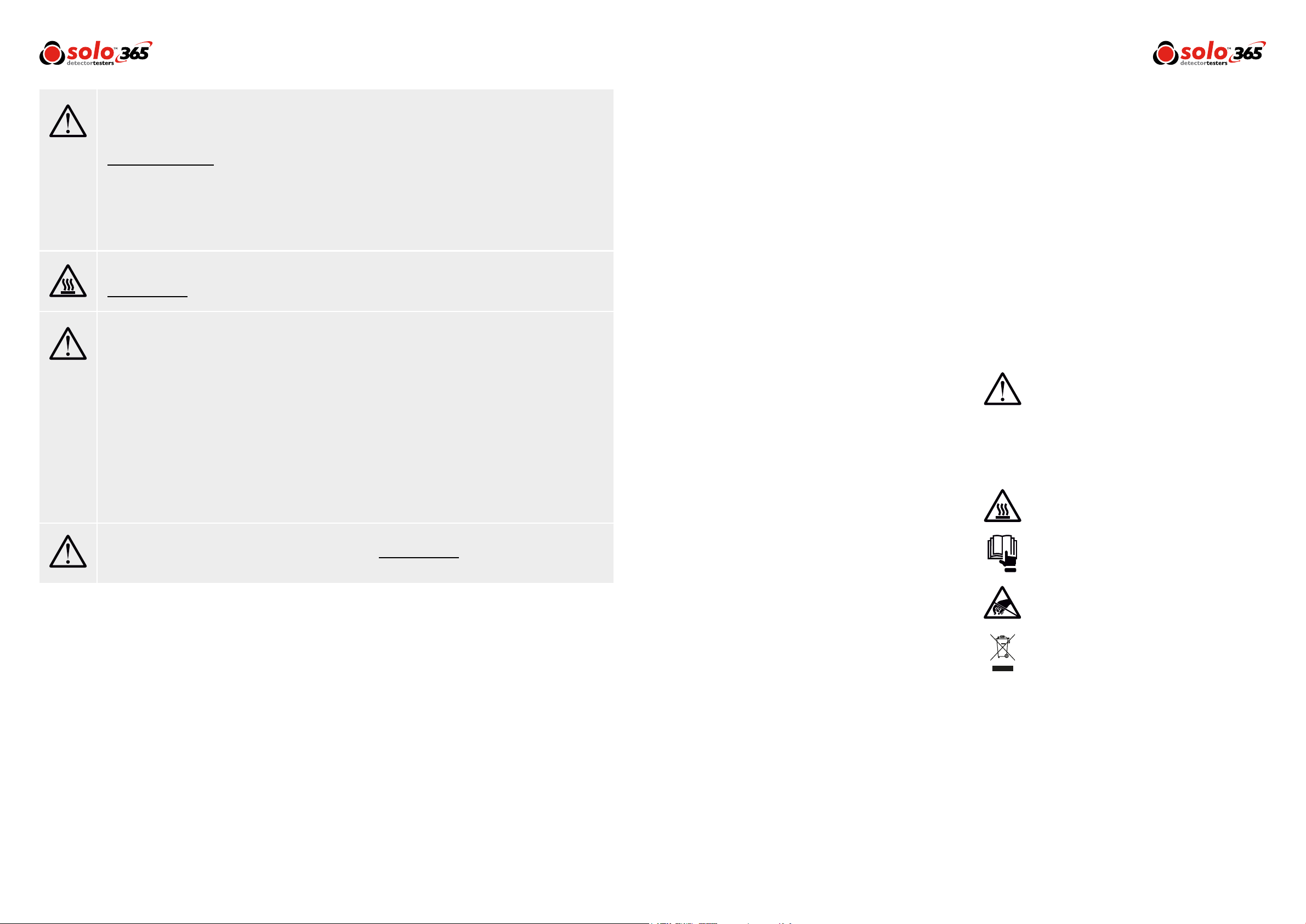
Symbols
The following symbols are used throughout this
User Manual and on the product.
This symbol on the product indicates that
there is a safety hazard or an operation
requiring care to avoid damage to the product
or environment. You must read the
appropriate sections of the User Manual to
understand the nature and severity of all the
potential hazards present and the action you
must take.
This symbol on the product warns you of hot
surfaces or heat by convection.
This symbol on the product indicates that you
should read and understand this User Manual
before using this product.
• Solo 365 may be used in ceiling and oor voids but
care must be taken to ensure that the unit and cup
can pass through gaps in both directions.
• Stop using Solo 365 immediately if you notice any
damage or unusual odours, liquids or sounds coming
from the unit. Turn the power off immediately and
consult technical support and troubleshooting (Section
8 onwards).
• Use only approved accessories as described in this
manual that are recommended by the manufacturer
for your Solo 365.
www.solo-tester.com www.solo-tester.com
2 3
This symbol on the product indicates that
this part of the device is susceptible to static
damage.
To comply with WEEE (Waste Electrical &
Electronic Equipment) Regulations the crossed
out refuse container symbol on this product
or literature indicates that it should not be
disposed with other business waste at the end
of its working life. To help ensure that valuable
resources are reused and recycled, and to
prevent possible harm to the environment
or human health from uncontrolled waste
disposal, please separate this from any other
types of waste.
Page 3
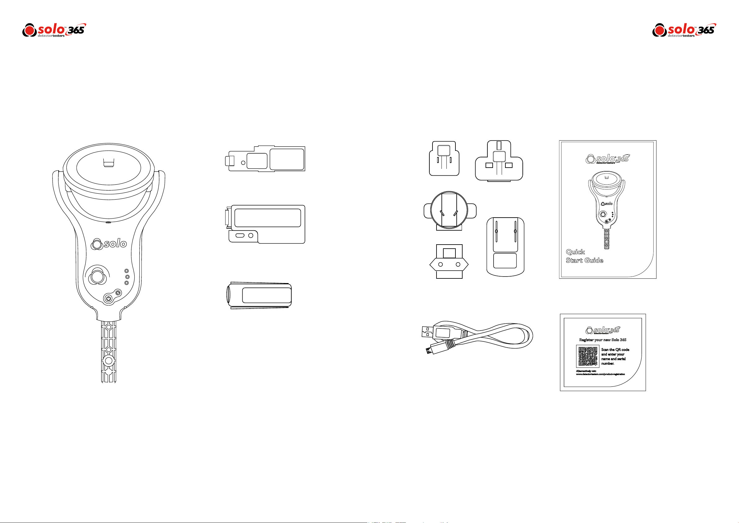
Kit Contents
Solo 365 Electronic Smoke Detector
Tester Kit containing:
Solo 371 Smoke Generator x 1
Solo 370 Lithium Ion Battery Pack x 1
Solo 365 Head Unit x 1
Solo ES3 Smoke Cartridge x 1
Solo 365 Universal USB Charger x1
USB Lead x1
Quick Start Guide x1
Product Registration Card x1
www.solo-tester.com www.solo-tester.com
4 5
Page 4

Contents
General
1
Table
Page 7
Page 8
Page 9
Page 10
Page 11
Page 12
Page 13
1 General Instructions
1.1 Warranty
1.2 Acknowledgement
1.3 Recycling
1.4 CE Declaration
2 Solo 365 Introduction
3 Preparation For First Use
3.1 Charging the Battery
3.2 Installing the Generator
3.3 Inserting the Smoke Cartridge
3.4 Inserting the Battery
4 Using Solo 365
4.1 Attaching Solo 365 to Solo Access Poles
4.2 Powering on Solo 365
4.3 Carrying Out a Simple Test
4.4 LED Indicator Reference Chart
4.5 Delayed Start
4.6 Clearing a Detector
4.7 Using the LED Torch
4.8 Testing an ASD System
4.9 Manual Purge
Page 14
Page 15
Page 16
Page 17
Page 18
Page 19
5 Removing & Replacing
5.1 Removing the Smoke Cartridge
5.2 Replacing the Smoke Cartridge
5.3 Removing the Smoke Generator
5.4 Replacing the Smoke Generator
5.5 Removing the Battery for Charging
5.6 Replacing the Battery
6 Consumables & Accessories
7 Spares
7.1 Removing the Clear Cup
7.2 Replacing the Clear Cup
7.3 Removing & Replacing the Membrane
8 Troubleshooting
9 Support & Technical
9.1 Maintenance
9.2 Technical Information
9.3 Support Contact
Instructions
1.1 Warranty
In addition to any other express warranty given in
writing by the Company in relation to the Goods,
the Company warrants that the Goods supplied
under these terms and conditions will be in
accordance with the specication (if any) contained
in the Purchase Order, and will be free from defects
in workmanship and material for a period of 18
months from the date of delivery to the Buyer or
for a period of 12 months after the date of sale by
the Buyer to the nal customer whichever period
is the shorter.
1.2 Acknowledgement
Solo™ is a registered trade mark of No Climb Products
Ltd. All other brand names mentioned are trademarks or
registered marks of their respective holders, and are
hereby acknowledged.
©2017 No Climb Products Ltd.
All Rights Reserved.
1.3 Recycling
The packaging can be easily separated into the following
materials:
• Cardboard (outer box)
• Cardboard (inner buffers, boxes)
• Polyethylene
• Plastic
Please dispose in line with local environmental
requirements.
1.4 CE Declaration
This product and its associated components are designed
and manufactured to be fully compliant with the
requirements of the following EU Directives for
CE marking:
• Directive 2014/30/EU of the European Parliament and
of the Council of 26 February 2014 on the
harmonisation of the laws of the Member States
relating to electromagnetic compatibility (recast).
• Low Voltage Directive 2006/95/EC of the European
Parliament and of the Council of 12 December 2006
on the harmonisation of the laws of Member States
relating to electrical equipment designed for use within
certain voltage limits.
• RoHS Directive 2011/65/EU of the European
Parliament and of the Council of 8 June 2011 on the
restriction of the use of certain hazardous substances in
electrical and electronic equipment.
www.solo-tester.com
6
WEEE (Waste Electrical & Electronic Equipment)
Regulations
Solo 365, accessories and batteries are suitably marked to
be recycled in accordance with your local environmental
requirements. Alternatively these items may be returned
to the manufacturer via your reseller for disposal in
compliance with WEEE (Waste Electrical & Electronic
Equipment) Regulations.
www.solo-tester.com
7
Page 5

Solo 365
2
Preparation
3
Introduction
Thank you for purchasing the Solo 365 Smoke Detector Tester.
This manual is designed to assist you to get the best and most efcient use of the Solo 365 and provides all the
information required to perform routine service and maintenance tasks with ease.
Solo 365 includes advanced technology that simplies functional testing of smoke detectors in the eld. By use
of electronically generated smoke health, safety, environmental and technological advantages are gained.
Design Features
1. Clear cup
2. Smoke outlet
3. Proximity sensor
4. Automatic LED torch
5. Air inlet
6. Power button
7. Status indicator LEDs
8. Locking button
9. Function button
10. Generator status LED
11. Cartridge status LED
12. Battery status LED
1
2 3
4
For First Use
Prior to rst use:
Check contents provided. Do not charge the battery
while it is tted in the unit. Take care during installation of
the product components not to touch exposed electrical
contacts. Ensure that all components are securely tted.
When replacing consumables, ensure that the unit is
switched off before opening back cover.
3.1 Charging the Battery
The battery is charged by connecting the battery pack to
the powered USB socket using the supplied mains adaptor.
Do not charge the battery while it is in place in the unit.
Ensure the battery is fully charged before use.
Warning
Read the cautions on Lithium Ion rechargeable
batteries before use (see Page 2).
3.2 Installing the Generator
• Open the back cover
• Remove protective packaging of generator.
Do not touch exposed electrical contacts.
• Insert generator rmly into recess, engaging clips 1
and 2 (see Fig.1).
• Once the generator is inserted do not remove it until
indicated that a replacement is necessary.
• When replacing a generator, any dust or debris within
the Solo 365 housing can be removed using an air
duster. Any condensation can be removed by wiping
with a lint-free cloth
• Empty generators may be returned to the
manufacturer via the reseller for environmentally
friendly disposal to comply with WEEE (Waste
Electrical & Electronic Equipment) Regulations
Figure 1
1
2
12
5
6
11
10
9
Battery LED:
|
|
|
|
77
|
|
|
|
|
|
|
Flashing Red/Green: Detecting level of charge
|
|
|
|
|
|
Solid Red: Charging
Solid Green: Fully charged
|
|
|
|
|
|
|
|
Flashing Red: Fault
|
|
|
|
|
8
Generator
|
|
|
|
|
|
Flashing Red: Consumable low
|
|
|
|
Solid Red: Consumable empty
www.solo-tester.com
8
www.solo-tester.com
9
Page 6

3.3 Inserting the Smoke Cartridge
• Remove cartridge from bag.
• Do not insert smoke cartridge until generator has
been fully tted into the main unit. See installing the
Generator section 3.2 (Page 9).
• Slide cartridge completely into generator housing
following the guide rails (Fig. 2).
• Once the cartridge is inserted into the generator do
not remove it until indicated that a
replacement is necessary. Do not re-use old
cartridges.
• Empty cartridges may be returned to the
manufacturer via the reseller for environmentally
friendly disposal to comply with WEEE (Waste
Electrical & Electronic Equipment) Regulations.
Do Not Touch
Do not touch the contacts on the PCB on the
cartridge. Static electricity may cause damage
and contamination of the contacts must be
avoided.
Figure 2
3.4 Inserting the Battery
• Once the battery is charged clip the battery pack into
the battery compartment. (Fig. 3).
• Do not force the battery into place.
• Close the back cover.
Do Not Touch
Do not touch the contacts on the battery.
Static electricity may cause damage and
contamination of the contacts must be
avoided.
Figure 3
Using
4
Solo 365
• Do not block air vents during use.
• Use only cartridges and batteries specied
by the manufacturer.
4.1 Attaching Solo 365 to Solo Access Poles
Solo 365 is designed for use with the Solo range of access
poles. (purchased separately). The product is not
compatible with alternative access poles.
• Take the Solo access pole and press down the locking
button on Solo 365. Align it with the location hole and
push the Solo 365 handle further into the pole until
the button springs up through the hole. Twist to lock.
(Fig. 4)
Figure 4
Caution
No more than 3 Solo 101 extension poles
should be used at the same time.
Warning
When working at height it is recommended
that a competent person carries out a suitable
risk assessment. This will identify any risk to the
user and/or the environment and hence any
need for Personal Protective Equipment.
NOTE: A Solo 101 extension pole can extend the Solo
100 and 108 telescopic poles, or may be used separately.
For further information on the correct use of poles, see
“Instructions for Solo Poles” document in the support
section of solo-tester.com
http://www.solo-tester.com/site/support
/product_manuals/
4.2 Powering on Solo 365
With the generator, cartridge and battery securely tted and
the back covered closed, the unit can now be powered on.
Power the unit on by holding down the power button for
3 seconds.
NOTE: After replacing a generator and powering on, a
‘purge cycle’ will run. During this the sound of the pump
operating may be heard. This will last for approximately a
few seconds after which, the unit will be ready for use.
The unit is functioning correctly if the status indicators are
ashing green slowly. If the status indicators are not
ashing green consult the indicator LED section (Page 12).
NOTE: If Solo 365 has been left unused for a period of
time then a manual purge may be required (Section 4.9).
www.solo-tester.com
10
Cartridge
|
|
|
|
|
|
Flashing Red: Consumable low
|
|
|
|
Solid Red: Consumable empty
Battery
|
|
|
|
|
|
Flashing Red: Consumable low
|
|
|
|
Solid Red: Consumable empty
www.solo-tester.com
11
Page 7

4.3 Carrying Out a Simple Test
Smoke generation will begin automatically once the smoke
detector enters the cup.
1) Raise Solo 365 up to the detector to be tested
2) Status indicator LEDs will ash fast blue once the
detector enters the cup
3) Detector will enter alarm once sufcient smoke
has been generated
4) Lower Solo 365
5) Status indicator LEDs will ash green
NOTE: For the best results the detector should be fully
within the cup. Solo 365 may be used in ceiling voids and
oor voids provided the detectors can be accessed safely.
The unit should not be forced through narrow gaps. If
the unit will not pass through a gap easily with the cup
orientated 90° to the normal position there is a possibility
it could become trapped.
Power On
Carefully place Solo 365 over the detector and
ensure that the detector is central in the cup.
Testing:
Smoke is generated and if the detector is functional it will be
activated.
Test Finish:
Carefully place Solo 365 over the detector and ensure that the
detector is central in the cup.
Clearing:
Clearing blows air into the detector to remove smoke. This
operation does not clean the internal parts of the detector. Once
detector is cleared lower Solo 365.
*After 2 minutes of testing or clearing, Solo 365 will
timeout indicated by alternate Green/Red ashing status indicator LEDs. Exit timeout by lowering Solo 365.
Main status indicators ash fast Blue*
Main status indicators ash fast Green*
Main status indicators ash fast White*
4.4 LED Indicator Reference Chart
Status Indicator LEDs
Solo 365 indicates events as follows:
When Idle:
|
|
|
|
|
|
|
Slow ashing Green: Power on
|
|
|
Solid Purple: System fault
|
|
|
|
|
|
|
|
|
|
Flashing Orange: Delayed start
|
|
|
|
|
|
|
Slow ashing Red: Consumable low
|
|
|
Solid Red: Consumable empty
When Active:
|
|
|
|
|
|
|
|
|
|
|
|
|
|
|
|
|
|
|
|
|
|
|
|
Fast ashing Blue: Testing normally
|
|
|
|
|
|
Fast ashing Green: Clearing ready
|
|
|
|
|
|
Fast ashing White: Clearing mode
|
|
|
|
Slow ashing Red/Green:Timeout in
|
|
|
|
testing or clearing modes
|
|
|
|
Fast ashing Red: Consumable low
|
|
Torch LED
Solid White: LED auto torch
Consumable LEDs
Solo 365 has three additional LEDs to show the
status of the battery, smoke cartridge and the smoke
generator. Warnings are indicated as follows:
Battery Cartridge
|
|
|
|
|
|
|
|
Flashing Red: Consumable low
|
|
Generator
Solid Red: Consumable empty
4.5 Delayed Start
On occasion it may be necessary to test detectors that do
not easily t into the Solo 365 smoke cup or are obstructed
in some way. To allow testing of such detectors or aspirating
smoke detection systems, Solo 365 has the facility to allow
a 20 second delayed start of a test.
• This feature can be activated by pressing the
function button on the front of the unit (Fig. 5)
momentarily (<1 second). The status indicators
will ash orange for 20 seconds allowing time to
reach the detectors/aspirating pipes.
• The status indicator LEDs will ash fast blue indicating
smoke generation for 20 seconds during which time
Solo 365 should be in proximity to the detector and/or
aspirating sample point.
• After 20 seconds of smoke generation the unit returns
to idle state and the status indicator ashes slow green.
Figure 5
4.6 Clearing a Detector
Once activated any lingering smoke can be cleared from
the detector using the ‘Clearing mode’. Air is blown around
the detector – clearing any lingering smoke via the vent in
the cup.
1) After the detector activates lower Solo 365 so the
detector is clear from the cup
2) The Status Indicator LEDs will ash fast green
3) Raise the unit over the detector again whilst the
status indicator LEDs are ashing fast green
4) The Status Indicator LEDs will ash fast white –
indicating clearing mode
4.7 Using the LED Torch
In low light levels an LED torch will automatically illuminate
from underneath the cup. This makes for easy alignment
and testing of detectors in dark environments.
Upon alignment and the starting of the test the LED torch
will switch off allowing a clear view of the detector LED
through the cup.
4.8 Testing an ASD System
An ASD System can be tested by using the ‘Delayed Start
Mode’ and replacing the cup with the Solo 365 ASD
Adaptor (Product Code: Solo 372-001).
1) With the unit facing you, remove cup by aligning
the notch on the left hand
side arm and disengage by squeezing the cup and
gently pulling the arm outwards
2) Rotate the cup to free it from the other arm
3) Fit the adaptor by locating into both arms
4) Raise the unit over the sampling hole and initiate
the test using the delayed start mode (Section 4.5)
4.9 Manual Purge
A manual purge may be required when the unit has not
been used for a period of time or in the case of a signicant
drop in performance. A manual purge should be carried out
in a well ventilated area as follows:
1) Hold down the function button continuously,
during this time Solo 365 will attempt to
generate smoke
2) When smoke has been observed for
approximately ve seconds release the
function button
3) Solo 365 will return to idle state – ready for
normal use
www.solo-tester.com
12
After clearing, the unit will return to idle state ready for the
next test.
NOTE: Clearing mode is not available when using the
delayed start feature.
www.solo-tester.com
13
Page 8

Removing & Replacing
5
Consumables
All critical parts of Solo 365 can be replaced in the eld
without having to return the unit for service. Ensure
that the unit is switched off during the replacement of
consumables. Do not touch electrical contacts.
5.1 Removing the Smoke Cartridge
1) Ensure the unit is switched off and open the back
cover
2) Remove the smoke cartridge from the generator
by placing your thumb in the recess and sliding
the cartridge along the guide rails (Fig. 6).
(Do not remove the generator).
5.2 Replacing the Smoke Cartridge
1) Remove the cartridge form the bag
2) Slide cartridge completely into generator housing
following the guide rails (Fiig. 7)
3) Once the cartridge is inserted into the generator
do not remove it until indicated that a
replacement is necessary.
NOTE: Do not re-use empty cartridges.Empty
cartridges may be returned to the manufacturer via the
reseller for environmentally friendly disposal to comply
with WEEE (Waste Electrical & Electronic Equipment)
Regulations.
5.3 Removing the Smoke Generator
1) Ensure the unit is switched off and the Smoke
Cartridge is removed (Section 5.1)
2) Disengage clip ‘1’ and lift. Repeat for clip ‘2’ to
remove the used generator (Fig. 8)
NOTE: When replacing the generator, any dust or debris
within the housing can be removed using an air duster. Any
condensation can be removed by wiping with a lint-free
cloth.
Figure 8
1
2
5.5 Removing the Battery for Charging
1) Ensure the unit is switched off and open the back
cover.
2) Unclip and remove the battery
3) Charge the battery by connecting the USB lead to
the battery and the powered USB socket using
the supplied mains adaptor or suitable source
(minimum 1A) (Fig. 10)
NOTE: Do not charge the battery while it is tted in the
unit.
Figure 10
Figure 6
Figure 7
Do Not Touch
Do not touch the contacts on the cartridge.
Static electricity may cause damage and
contamination of the contacts must be
avoided.
5.4 Replacing the Smoke Generator
1) Insert the generator rmly into the recess,
engaging clips ‘1’ and ‘2’ (Fig. 9)
NOTE: Once the generator is inserted do not remove it
until it is indicated that a replacement is necessary.
Figure 9
1
2
5.6 Replacing the Battery
1) Once the battery is charged clip into the battery
compartment and close the back cover (Fig. 11)
NOTE: Do not force the battery into place.
Figure 11
www.solo-tester.com
14
Do Not Touch
Do not touch the contacts on the generator.
Static electricity may cause damage and
contamination of the contacts must be
avoided.
Do Not Touch
Do not touch the contacts on the battery.
Static electricity may cause damage and
contamination of the contacts must be
avoided.
www.solo-tester.com
15
Page 9

Consumables
6
& Accessories
Spares7
Consumables
ES3-12 PACK-001
SOLO3701 PACK-001
SOLO3704 PACK-001
SOLO371-001
SERVICE360-001
Accessories
SOLO372-001
Spares
SPARE1058-001
SPARE1059-001
SPARE1060-001
Solo 365 Smoke Cartridges x12
Solo 365 Lithium Ion Battery
Pack x1
Solo 365 Lithium Ion Battery
Pack x4
Solo 365 Smoke Generator
Solo 365 Service Pack containing:
Spare 1058 x 1, Solo 370 x 1 &
Solo 371 x 1
Solo 365 ASD Adaptor
Clear Cup & Membrane
for Solo 365
Membrane for Solo 365
Solo Charger & USB Lead
7.1 Removing the Clear Cup
1) Align the notch on the left hand side arm and
disengage by squeezing the cup and gently
pulling the arm outwards. (Fig. 12)
2) Rotate the cup to free it from the other arm
Figure 12
7.3 Removing & Replacing the Membrane
1) Ease the membrane off the clear cup gently
2) Take the replacement membrane and stretch it
over the clear cup (Fig. 13)
Figure 13
www.solo-tester.com
16
7.2 Replacing the Clear Cup
1) Engage the cup with the notch on the left hand
arm and rotate the cup to engage with the notch
on the right hand side
NOTE: Ensure the cup vent is the same side as the back
of the unit
www.solo-tester.com
17
Page 10

Support
Troubleshooting8
9
& Technical
If when testing, a detector does not activate, repeat the
test every10 seconds for up to 2 minutes by keeping the
unit at the detector. If the detector still does not activate it
may be faulty and need replacement. Should the status
indicator LEDs turn purple, an internal fault has
occurred and the following steps should be taken:
1) Power the unit off and on again.
2) If the problem remains ensure that Solo 365 is
powered off before performing any of the
following steps:
3) Remove and re-insert the generator, at the same
time check the PCB contacts for any debris.
4) Power the unit off, remove the battery. Check
the fan moves freely, if not remove the smoke
cartridge and generator from within Solo 365.
Fan faults may occur due to debris getting inside
the unit. Carefully use an air duster and apply to
the fan or rotate the fan gently. The use of an air
duster such as Solo A7 normally frees the fan of
debris. Re-insert the battery and power the
unit on.
Unit does not switch on
Check the battery indicator. If solid red, remove
the battery from the unit and recharge it.
Smoke not being generated
If the cartridge indicator shows red change the
cartridge.Check the generator indicator. If this is
solid red then change the generator.
Fan is not rotating
Check for obstructions. Use an air duster to
clear debris.
9.1 Maintenance
The Solo 365 unit contains no user serviceable parts. Do not disassemble. In the case of a build-up of dust or dirt on the surface
of the product, wipe with a slightly damp lint-free cloth. The area around the smoke duct and within the cup should be cleaned
periodically to remove any dirt or uid. This can also be done using a slightly damp lint-free cloth. Do not use detergents, cleaning
materials or solvents such as petroleum spirit, benzene or methylated spirit to clean the product.
9.2 Technical Information
Operating features
Safety features
Power source
Battery charging time
Operating temperature range
Operating humidity range
- Colour coded LED user information
- Proximity sensor starts test
- Suitable for detectors up to 110mm diameter
- 5 seconds of stimulus, 5 seconds off repeat cycles
- Battery over current cut out
- Over temperature cut out
- 2 minutes maximum duration time-out
- Auto power off after 10 minutes
Lithium Ion battery pack nominal 3.63V 9.5Wh,
with USB charger connection
~2 hours
+5°C to 45°C (+41°F to 113°F)
0 to 85% RH non-condensing
5) If the problems remain, please contact
support@detectortesters.com
www.solo-tester.com www.solo-tester.com
18 19
Storage temperature range
Storage humidity range
Weight
Dimensions H (including handle) x W (widest) x D
Dimensions H (excluding handle) x W (widest) x D
Dimensions as above with cup in user position
Clear cup dimensions
9.3 Support Contact
No Climb Products Ltd.
Edison House, 163 Dixons Hill Road, Welham Green,
Herts, AL9 7JE, United Kingdom
Tel: +44 (0) 1707 282760 Fax: +44 (0) 1707 282777
Email: support@detectortesters.com
-10°C to 50°C (+14°F to 122°F)
0 to 90% RH non-condensing (up to +35°C/95°F)
860g
420mm x 190mm x 110mm
295mm x 190mm x 110mm
260mm x 190mm x 150mm
150mm x 85mm
Page 11

No Climb Products Ltd
Edison House,163 Dixons Hill Road,
Welham Green Hertfordshire, AL9 7JE,
United Kingdom
Tel: +44 (0) 1707 282 760
Fax: +44 (0) 1707 282 777
Info@detectortesters.com
As our policy is one of continuous improvement, details of products described within this publication are subject to change without notice. All information provided
here is believed to be correct at the time of going to press. Every effort has been made to ensure the accuracy of information which is provided in good faith but
nothing contained herein is intended to incorporate any representation or warranty, either express or implied or to form the basis of any legal relations between the
parties hereto, additional to or in lieu of such as may be applicable to a contract of sale or purchase.
www.solo-tester.com
LI39116-2
 Loading...