

Solo 2 625 02, 2 625 02i, 2 625 01 Service Manual
solo
service
Service-manual
For the aircraft engines
solo 2 625 01
solo 2 625 02
solo 2 625 02i
solo Kleinmotoren GmbH
Stuttgarter Str. 41
D 71069 Sindelfingen
Tel.: (0049) 7031 - 3010
Fax.: (0049) 7031 – 301195
Edition 4 dated February 26th 2018
Baureihe
2 625 01
2 625 02
2 625 02 i
Service Manual
SOLO
KLEINMOTOREN
GMBH
edition 4 dated 26.02.2018 Seite 2
Table of contents
1 General hints and description of the engines ............................................................ 2
2 Necessary tools ........................................................................................................ 4
3 Disassembly of the engine ........................................................................................ 5
4 Check of the individual parts ..................................................................................... 6
4.1 Cylinder heads .......................................................................................................... 6
4.2 Cylinders ................................................................................................................... 6
4.3 Piston and piston rings ............................................................................................. 6
4.4 Crankshaft ................................................................................................................ 7
4.5 Ignition system .......................................................................................................... 7
4.5.1 Engines 2625 01 and 2625 02 .................................................................................. 7
4.5.2 Troubleshooting ignition systems .............................................................................. 8
4.5.3 Wire diagrams Iskra and ducati ignition systems ...................................................... 9
4.6 Engine Control Unit (ECU) ...................................................................................... 10
4.6.1 Wire diagram ECU 2625 02 i .................................................................................. 10
4.6.2 Wire diagram redundancy system of the engine 2625 02 i ..................................... 11
4.7 Carburettor .............................................................................................................. 12
4.7.1 Specialties MIKUNI BN 38 ..................................................................................... 12
4.7.2 Specialties MIKUNI BN 38-34-55 ............................................................................ 13
4.7.3 Adjustment of the carburettors ................................................................................ 14
4.7.4 Troubleshooting at the carburettors ........................................................................ 15
4.8 Trouble shooting at the fuel injection system (only 2625 02 i) ................................ 16
4.8.1 Engine does not start .............................................................................................. 16
4.8.2 Failures during operation ........................................................................................ 16
4.8.3 Failure memory ....................................................................................................... 16
4.8.4 Software for the ECU .............................................................................................. 16
5 Assembly of the engine ........................................................................................... 18
6 Notes ....................................................................................................................... 20
1 General hints and description of the engines
This service – manual shall give the engine specialist necessary hints for repairs and
overhauls for the engine and help him solving specific problems. General knowledge
of two-stroke-engines should be present.
This Service-manual is valid together with the engine-manual and the spare-partslist.
! Attention!
Because this engine is used as a certified engine for motor gliders the national
authorizations of the specific certifying staffs must be maintained.

Baureihe
2 625 01
2 625 02
2 625 02 i
Service Manual
SOLO
KLEINMOTOREN
GMBH
edition 4 dated 26.02.2018 Seite 3
Description of the engines
The aircraft engines 2625 01, 2625 02 and 2625 02i are based on the same engine
block and differ only by different carburetors or at the engine 2 625 02i by the use of
an electronic fuel injection. The engines 2625 02 and 2625 02i have a different
cylinder with a different port timing of the intake port. All three engines are watercooled two cylinder two-stroke engines with piston-ports. They have a displacement
of 625 cm3 with a stroke of 69 mm and a bore of 76 mm. They are lubricated by a
fuel-oil mixture. For all engines a breaker less double ignition is used.
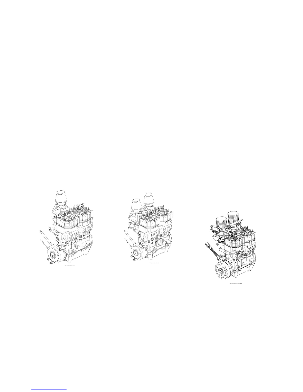
Aircraft engine 2625 01
This engine has one diaphragm carburetor, which feeds both cylinders and a take-off
power of 39 kW at a speed of 6.250 RPM.
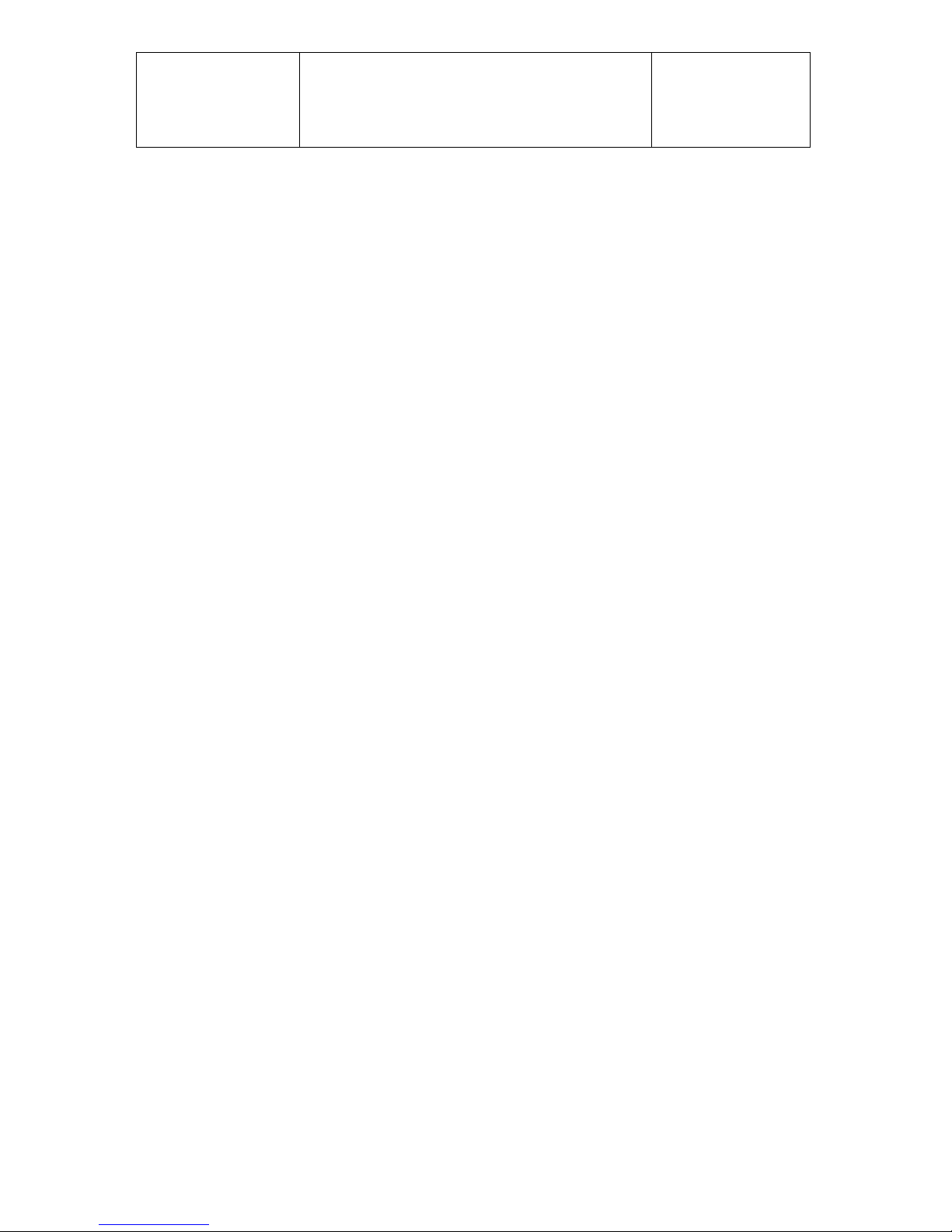
Aircraft engine 2625 02
This engine has a different intake-port timing compared to the engine 01 and two
diaphragm carburetors. The take-off power is 47 kW at a speed of 6.500 RPM
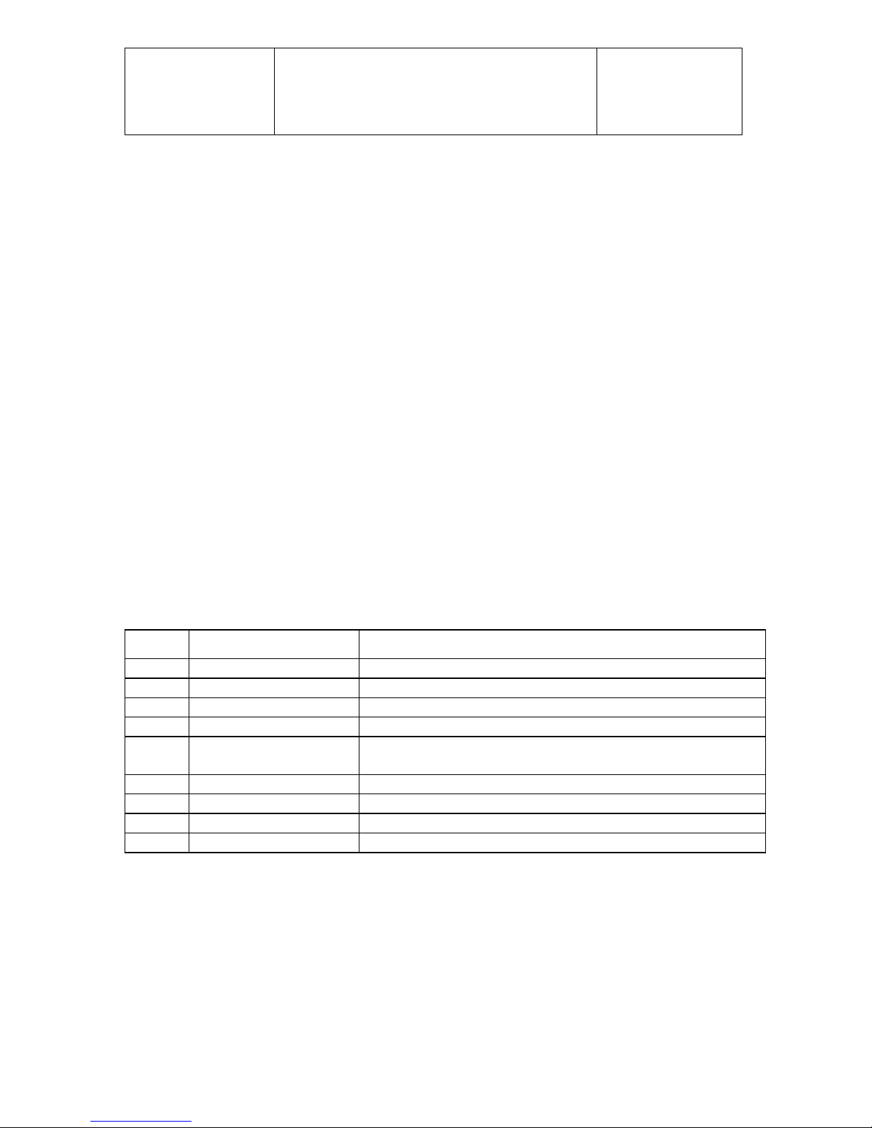
Aircraft engine 2625 02i
This engine is based on the engine 2625 02, which is converted according to the
Service bulletin TM 4603 – 3 to the version with electronic fuel injection. The
carburetors and the ignition system are replaced by this electronic fuel injection
system into the manifolds and also by an electronic ignition system. The former
ignition system is replaced by an alternator, which supplies sufficient electric energy
to operate the fuel injection and the ignition. The take-off power is 50 kW by a speed
of 6.500 RPM.
An ECU is controlling the injected amount of fuel and the ignition timing based on the
engine speed, the position of the throttle valve, the engine temperature, the ambient
pressure and the outside air temperature. This guaranties that the engine is running
under optimal conditions.
In order to achieve maximum security in case of a breakdown of the ECU a simple
redundancy system is installed, which supplies the engine with two additional
injection valves. An ignition module which is driving the two coils of the engine is
integrated in this system. The system is controlled by an additional RPM-sensor.
Other sensors are not necessary.
The engine management system is consisting of the following components:
• Pre-filter, fuel pump, micro filter and fuel pressure regulator for the fuel supply.
The fuel pressure in the system is regulated by the pressure regulator at 3
bars. The fuel line from the pressure regulator back to the fuel tank is pressure
less.
• Engine Control Unit with ignition modules and a pressure sensor, which
measures the atmospheric pressure. In the ECU the maps for fuel injection
and ignition timing are stored. Based on the air pressure and the air
temperature the ECU calculates the correct amount of injected fuel.
• The engine has 5 sensors. Facing the flywheel of the alternator there is an
RPM sensor. At the throttle valve there is a sensor, which measures the
opening of the shutter valve. At the rear cylinder head there is a temperature
sensor measuring the coolant temperature. Near the air filters there is a
Baureihe
2 625 01
2 625 02
2 625 02 i
Service Manual
SOLO
KLEINMOTOREN
GMBH
edition 4 dated 26.02.2018 Seite 4
sensor measuring the intake air temperature. In the ECU there is a pressure
sensor measuring the atmospheric pressure.
• A double throttle valve assembly and one injection valve each, which are
controlled by the ECU.
• Two double ignition coils with ignition wires leading to the front and rear
cylinder each. The engine is running with minimal power loss fired by only one
coil.
If a sensor fails or a wire breaks standard values are stored in the ECU which
guarantee a limited operation of the engine. Only if the speed sensor fails the engine
stops. The ECU supplies constantly values about speed, temperatures and the
condition of the sensors via a CAN-bus, which can be displayed to the pilot. In
addition to that there is a failure memory, which can be read by the software Win
trijekt. With this memory it can be detected, if one or more values have exceeded
their limits. Short above the maximum engine speed the ignition is cut off. The
starting of the engine must always be in idle position. A choke or other fuel
enrichment systems are not necessary. The ECU has a serial interface, which allows
the detection of the status of the ECU in operation. Special software is necessary for
that. The settings and the access to the failure memory are protected by a password.
2 Necessary tools
In order to conduct an expert repair or check it is necessary to use functional tools in
good condition. Except the usual tools, present in each engine workshop the
following special tools are necessary.
Pos.
SOLO order No.
Description
1
00 80 529
Puller for hub
2
00 80 530
Puller for Ignition flywheel
3
00 80 314
Pressure tester
4
Two stroke oil Castrol ACT>EVO, Castrol Super Two
Stroke, Other oils with specification JASO FC or FD
5
00 83 177
Air filter oil 6
Loctite 274 7
Loctite 270 8
Loctite 574
Baureihe
2 625 01
2 625 02
2 625 02 i
Service Manual
SOLO
KLEINMOTOREN
GMBH
edition 4 dated 26.02.2018 Seite 5
3 Disassembly of the engine
Pos.
Operation
Tools, aid
1
Clean engine before disassembly
Use fuel
2
Disassemble carburetor from manifold
Open end spanner 13 mm
3
Disassemble muffler, clean muffler from debris
and coal.
Allen key 6 mm
4
Loosen flywheel of the ignition system and pull
off flywheel with suitable puller.
Puller SOLO-No. 00 80 530
5
Disassemble the stator of the ignition system
completely. If the engine has an ignition
system from Ducati disassemble also the plate
with the pick-ups.
6
Loosen hub at the front end of the crankshaft
and pull off with the suitable puller.
Socket wrench 19 mm
Puller SOLO No. 00 80 529
7
Loosen nuts at the cylinder head.
Socket wrench 13 mm
8
Lift cylinder head.
9
Mark cylinder head, cylinder and piston for
matching.
10
Loosen nuts at the bottom of the cylinder and
lift cylinder carefully.
Open end spanner 12 mm
11
Disassemble the piston-pin lock carefully. Push
piston-pin out of the piston by hand.
12
Loosen the 4 bolts on the side of the crankcase
and move the two halves of the crankcase
apart carefully so that they don’t get out of line.
Clean both parts.
ATTENTION! ON ENGINES WITH DOUBLE
BEARING ON THE DRIVE SIDE LOOSEN THE
FOUR BOLTS AT THE FRONT-END FIRST.
13
Take off seals, locks and outer rings of the
roller bearings by hand.
Baureihe
2 625 01
2 625 02
2 625 02 i
Service Manual
SOLO
KLEINMOTOREN
GMBH
edition 4 dated 26.02.2018 Seite 6
4 Check of the individual parts
4.1 Cylinder heads
• Clean the inside part of the cylinder head from coal. Fuel can dissolute rests of
burnt oil. Heavy oil-carbon deposit can be removed with a steel brush.
• Check both threads for the spark-plugs if damaged
• Clean the sealing surface.
4.2 Cylinders
• Check the cylinder surface (Coating) visually if there are damages
(Scratches).
• Check the diameter of the cylinder in direction of the crankshaft and
rectangular:
Dimension
New
Wear limit
10 mm below top
76 mm +/- 0,005
76,01 mm
30 mm below top
76,mm +/- 0,005
76,01 mm
25 mm above bottom
76 mm +0,01
76,02 mm
• Check visually the grooves for the o-rings at the top of the cylinder.
• Check the entire cylinder for cracks or damages of the sealing surfaces.
• Remove oil-carbon deposit on the coating and in the exhaust port.
4.3 Piston and piston rings
• Remove oil-carbon deposit on the piston top carefully.
• Check piston diameter. Measure the diameter rectangular to the piston pin
boss.
Dimension
New
Wear limit
D1=DN 22 mm above
bottom
76 mm +/- 0,06
75,9 mm
D2: 59,5 mm above
bottom
76 mm +/- 0,08
75,8 mm
D3: 69 mm above
bottom
76 mm - 0,093
75,7 mm
• Check vertical play of the piston rings
New 0,05 mm - 0,10 mm wear limit 0,20 mm
• Check wear of the piston rings.
Distance between the two ends if the piston ring is mounted into the cylinder:
New 0,2 - 0,35 mm wear limit 0,8 mm
No light has to be seen between cylinder wall and piston ring if the cylinder is
hold against a lamp.
 Loading...