

Page 1
TT
yryr
es Equipment & es Equipment &
T
yr
es Equipment &
TT
yryr
es Equipment & es Equipment &
EQUILIBRATRICE
TT
oolsools
T
ools
TT
oolsools
I
UK
F
D
ES
CSI
БАЛАНСИРОВОЧНЫЙ СТАНОК
COD.655632 Rev.0
WHEEL BALANCER
EQUILIBREUSE
AUSWUCHTMASCHINE
EQUILIBRADORA
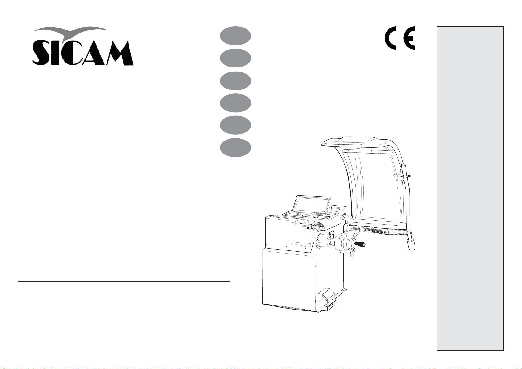
SBM 155
РУКОВОДСТВО ПО ЭКСПЛУАТАЦИИ
LIBRETTO DI ISTRUZIONI ED AVVERTENZE
ANLEITUNGSHINWEISE - MANUAL DE INSTRUCCIONES
INSTRUCTIONS MANUAL - MANUEL D’INSTRUCTIONS
Page 2
ITALIANO
ENGLISH
FRANÇAIS
AVVERTENZE
Il presente libretto di istruzioni costituisce parte integrante del prodotto. Leggere attentamente le
avvertenze e le istruzioni in esso contenute in quanto forniscono importanti indicazioni riguardanti la
sicurezza d’ uso e manutenzione.
Conservare con cura questo libretto per ogni ulteriore consultazione.
L’ EQUILIBRATRICE SBM 155 E’ UNA MACCHINA PROGETTATA E COSTRUITA PER ESSERE
UTILIZZATA QUALE ATTREZZATURA PER L’EQUILIBRATURA DELLE RUOTE DI
AUTOVETTURE, FURGONI E MOTOCICLI.
LA MACCHINA E’ STATA PREVISTA PER FUNZIONARE ENTRO I LIMITI INDICATI NEL PRESENTE
LIBRETTO ED IN ACCORDO ALLE ISTRUZIONI DEL COSTRUTTORE.
La macchina dovrà essere destinata solo all’uso per il quale è stata espressamente concepita. Ogni
altro uso è da considerarsi improprio e quindi irragionevole.
Il costruttore non può essere considerato responsabile per eventuali danni causati da usi
impropri, erronei ed irragionevoli.
Questo simbolo viene utilizzato nel presente manuale quando si vuole attirare l’attenzione
dell’operatore su particolari rischi connessi con l’uso della macchina.
WARNINGS
The present instructions booklet is an integral part of the product. Carefully study the warnings and
instructions contained in it. This information is important for safe use and maintenance.
Conserve this booklet carefully for further consultation.
THE WHEEL BALANCER SBM 155 IS A MACHINE DESIGNED AND CONSTRUCTED FOR THE
BALANCING OF CAR, VAN, AND MOTORCYCLE WHEELS.
THE MACHINE HAS BEEN DESIGNED TO OPERATE WITHIN THE LIMITS DESCRIBED IN THIS
BOOKLET AND IN ACCORDANCE WITH THE MAKER’S INSTRUCTIONS.
The machine must be used only for the purpose for which it was expressly designed. Any other use is
considered wrong and therefore unacceptable.
The maker cannot be held responsible for eventual damage caused by improper, erroneous, or
unacceptable use.
This symbol is used in the present manual to warn the operator of particular risks associated with
the use of the machine.
AVERTISSEMENTS
Ce manuel d’instructions fait partie intégrante du produit. Lire attentivement les avertissements et
les instructions données car elles fournissent d’importantes indications concernant la sécurité
d’emploi et d’entretien.
Conserver avec soin pour toute consultation.
L’EQUILIBREUSE SBM 155 EST UNE MACHINE CONÇUE ET CONSTRUITE POUR
L’EQUILIBRAGE DES ROUES DE VOITURES, FOURGONS ET MOTOCYCLES.
L’APPAREIL A ÉTÉ PRÉVU POUR FONCTIONNER DANS LES LIMITES INDIQUÉES DANS CE
MANUEL ET SELON LES INSTRUCTIONS DU CONSTRUCTEUR.
L’appareil ne devra être destiné qu’à l’emploi pour lequel il a été proprement conçu. Tout autre emploi
doit être considéré abusif et donc inadmissible.
Le constructeur ne pourra être considéré responsable des éventuels dommages causés à la
suite d’emplois abusifs, fautifs et inadmissibles.
Ce symbole est utilisé dans ce manuel pour attirer l’attention de l’opérateur sur des risques
particuliers dérivant de l’utilisation de la machine.
INDICE
AVVERTENZE GENERALI E INDICE ........................................................................................... 2
PRINCIPALI PARTI COMPONENTI .............................................................................................. 4
CARATTERISTICHE TECNICHE.................................................................................................. 4
ACCESSORI (in dotazione e a richiesta) ....................................................................................... 6
DISIMBALLO E COLLOCAMENTO .............................................................................................. 8
INSTALLAZIONE
- Collegamento elettrico .............................................................................................................. 10
- Installazione flange ................................................................................................................... 12
MALFUNZIONAMENTI, LORO CAUSE E POSSIBILI RIMEDI .............................................. 16
ISTRUZIONI PER L’USO
- Pannello comandi ...................................................................................................................... 22
- Equilibratura ruote ..................................................................................................................... 24
- Selezione programma di equilibratura ..................................................................................... 26
- Impostazione dati ruota (con calibro automatico e con calibro manuale) ............................. 26
- Programmazione e fissaggio pesi adesivi con calibro speciale
(per cerchi in alluminio o lega leggera) .................................................................................... 28
- Programma di separazione dei pesi ......................................................................................... 30
- Ottimizzazione squilibrio .......................................................................................................... 32
- Configurazione equilibratrice .................................................................................................... 34
- Taratura base della macchina .................................................................................................. 36
- Taratura calibri automatici ........................................................................................................ 38
- Autodiagnosi .............................................................................................................................. 40
- ALUDATA.................................................................................................................................... 42
MANUTENZIONE ORDINARIA .................................................................................................. 44
MOVIMENTAZIONE ACCANTONAMENTO E ROTTAMAZIONE........................................... 44
ISTRUZIONI RELATIVE ALLA CORRETTA GESTIONE DEI RIFIUTI DA
APPARRECCHIATURE ELETTRICHE ED ELETTRONICHE (RAEE) AI SENSI DELLA
DIRETTIVE 2002/96/CE E 2003/108/CE ................................................................................... 46
ASSISTENZA TECNICA E PARTI DI RICAMBIO ..................................................................... 48
CONTENTS
GENERAL WARNINGS AND CONTENTS ................................................................................... 2
MAIN COMPONENT PARTS ......................................................................................................... 4
TECHNICAL CHARACTERISTICS ............................................................................................... 4
ACCESSORIES (Provided and on request)................................................................................... 6
UNPACKING AND LOCATION...................................................................................................... 8
INSTALLATION
- Electrical connection ................................................................................................................ 10
- Fitting the adapter ..................................................................................................................... 12
TROUBLE SHOOTING FAULTS ............................................................................................... 17
INSTRUCTIONS FOR USE
- Control panel.............................................................................................................................. 22
- Balancing wheels ...................................................................................................................... 24
- Selecting balancing program .................................................................................................... 26
- Setting wheel data (with automatic gauge and manual gauge) ............................................. 26
- Programming and fixing adhesive weights with the special gauge
(for aluminium or light alloy rims) ............................................................................................. 28
- Weight separation program ....................................................................................................... 30
- Optimising imbalance ............................................................................................................... 32
- Wheel balancer configuration ................................................................................................... 34
- Basic machine calibration ........................................................................................................ 36
- Calibrating the automatic gauges ............................................................................................. 38
- Auto-diagnosis ........................................................................................................................... 40
- ALUDATA.................................................................................................................................... 42
ROUTINE MAINTENANCE ......................................................................................................... 44
TRANSPORT, STORAGE, AND SCRAPPING .......................................................................... 44
INSTRUCTIONS FOR THE CORRECT MANAGEMENT OF WASTE MATERIAL
FROM ELECTRIC AND ELECTRONIC DEVICES (WEEE) UNDER THE 2002/96/CE
E 2003/108/CE DIRECTIVE ........................................................................................................46
TECHNICAL ASSISTANCE AND SPARE PARTS ..................................................................... 48
COD. 655632 Rev.0
INDEX
AVERTISSEMENTS GENERAUX ET INDEX ............................................................................... 2
PARTIES COMPOSANTES PRINCIPALES ................................................................................. 5
CARACTERISTIQUES TECHNIQUES ......................................................................................... 5
ACCESSOIRES (en dotation et sur demande) ............................................................................. 7
DEBALLAGE ET MISE EN PLACE .............................................................................................. 9
INSTALLATION
- Branchement électrique ............................................................................................................. 11
- Installation des plateaux .......................................................................................................... 13
ANOMALIES, CAUSES ET REMÈDES POSSIBLES ............................................................. 18
INSTRUCTIONS D’UTILISATION
- Panneau de commandes ..........................................................................................................22
- Equilibrage des roues ................................................................................................................ 25
- Sélection de la programmation équilibrage ............................................................................ 27
- Introduction des données des roues avec pige automatique et manuelle ............................ 27
- Programmation et fixation des masses collantes par pige spéciale
(pour des jantes en alu ou en alliage léger) ........................................................................... 29
- Programme de séparation des masses .................................................................................... 31
- Optimisation du balourd ............................................................................................................ 32
- Configuration de l’équilibreuse ................................................................................................ 34
- Tarage de base de la machine ................................................................................................. 37
- Etalonnage des piges automatiques ........................................................................................ 38
- Autodiagnostic ........................................................................................................................... 40
- ALUDATA .................................................................................................................................... 42
ENTRETIEN COURANT ............................................................................................................. 45
MANUTENTION, INACTIVITE DE LA MACHINE ET DEMOLITION ...................................... 45
INDICATIONS RELATIVES A LA GESTION CORRECTE DES DÉCHETS PAR
L’INTERMEDIAIRE D’ÉQUIPEMENTS ÉLECTRIQUES ET ÉLECTRONIQUES (DEEE) ... 46
ASSISTANCE TECHNIQUE ET PIECES DETACHEES ........................................................... 48
2
Page 3
DEUTSCH
ESPAÑOL
РУССКИЙ
HINWEISE
Das vorliegende Anleitungsheft stellt einen Teil des Produkts dar. Lesen Sie aufmerksam die darin
enthaltenen Hinweise und Anleitungen, da diese wichtige Angaben bezüglich der Sicherheit, der
Anwendung und der Wartung enthalten.
Dieses Heft für weiteres Nachschlagen sorgfältig aufbewahren.
DIE AUSWUCHTMASCHINE SBM 155 IST EINE MASCHINE, DIE ZUR ANWENDUNG ALS
AUSSTATTUNG FÜR DIE AUSWUCHTUNG VON KRAFTFAHRZEUGEN, LASTWAGEN UND
MOTORRADRÄDERN ENTWORFEN UND GEBAUT WURDE.
DAS GERÄT IST GEMÄß DER HERSTELLERVORGABEN FÜR DEN IN DER VORLIEGENDEN
BEDIENUNGSANLEITUNG ANGEGEBENEN FUNKTIONSBEREICH VORGESEHEN.
Das Gerät darf ausschließlich zu dem ihm eigenen Zweck benutzt werden. Jeder andere Einsatz ist
deshalb als unsachgemäß und unvernünftig anzusehen.
Der Hersteller haftet nicht für eventuelle Schäden, die aus unsachgemäßem, fälschlichem und
unvernünftigem Gebrauch herrühren.
Dieses Symbol wird im vorliegenden Handbuch verwendet, wenn die Aufmerksamkeit des
Bedieners auf besondere Risiken im Zusammenhang mit dem Gebrauch der Maschine gelenkt
werden soll.
ADVERTENCIAS
El presente manual de instrucciones forma parte integrante del producto. Leer atentamente las
advertencias y las instrucciones que se señalan en el mismo, ya que suministran indicaciones importantes
referentes a la seguridad del uso y mantenimiento.
Conservar con cuidado este manual para ulteriores consultas.
LA EQUILIBRADORA SBM 155 ES UNA MÁQUINA PROYECTADA Y CONSTRUIDA PARA SER
UTILIZADA COMO EQUIPAMIENTO PARA EL EQUILIBRADO DE LAS RUEDAS DE VEHÍCULOS,
FURGONETAS Y MOTOCICLETAS.
LA MAQUINA HA SIDO IDEADA PARA FUNCIONAR DENTRO DE LOS LIMITES INDICADOS EN EL
PRESENTE MANUAL DE USO Y EN CONFORMIDAD A LAS INSTRUCCIONES DEL CONSTRUCTOR.
La máquina debe contemplar un uso adecuado únicamente a su ideación. Cualquier otro tipo de uso
está considerado como impropio y por lo tanto irrazonable.
No se ha de considerar responsable al constructor si la máquina sufrirá daños causados por
un uso inadecuado y erróneo.
Este símbolo se utiliza en el presente manual cuando se desea llamar la atención del operador
sobre particulares riesgos relacionados con el uso de la máquina.
РЕКОМЕНДАЦИИ
Настоящая инструкция по эксплуатации является неотъемлемой частью станка.
Необходимо тщательно изучить содержащиеся в ней рекомендации и инструкции, так
как они предоставляют важную информацию, касающуюся безопасности эксплуатации
и техобслуживания.
Данная инструкция должна сохраняться для ее дальнейшего использования.
БАЛАНСИРОВОЧНЫЙ СТАНОК SBM 155 РАЗРАБОТАН И ИЗГОТОВЛЕН ДЛЯ
ИСПОЛЬЗОВАНИЯ ПРИ БАЛАНСИРОВКЕ КОЛЕС ЛЕГКОВЫХ АВТОМОБИЛЕЙ,
ФУРГОНОВ И МОТОЦИКЛОВ.
СТАНОК БЫЛ РАЗРАБОТАН ДЛЯ ЭКСПЛУАТАЦИИ В РАБОЧИХ УСЛОВИЯХ, УКАЗАННЫХ В
НАСТОЯЩЕМ РУКОВОДСТВЕ, И В СООТВЕТСТВИИ С УКАЗАНИЯМИ ИЗГОТОВИТЕЛЯ.
Станок должен применяться для выполнения только тех операций, для которых он был специально
разработан. Любое другое его применение должно считаться неправильным и не по назначению.
Изготовитель не может быть привлечен к ответственности за повреждения, вытекающие
из неправильного или ошибочного применения, и использования не по назначению.
Этот символ используется в настоящем руководстве в том случае, когда хотят обратить
внимание обслуживающего персонала на особые риски связанные с эксплуатацией станка.
INHALTSVERZEICHNIS
ALLGEMEINE HINWEISE UND INHALTSVERZEICHNIS ......................................................... 3
HAUPÜTKOMPONENTEN ........................................................................................................... 5
TECHNISCHE EIGENSCHAFTEN ............................................................................................... 5
ZUBEHÖR (Lieferumfang und auf Anfrage) ................................................................................. 7
ENTFERNEN DER VERPACKUNG UND POSITIONIERUNG .................................................... 9
INSTALLATION
- Elektrischer Anschluss .............................................................................................................. 11
- Installation der Flansche .......................................................................................................... 13
BETRIEBSSTÖRUNGEN, IHRE URSACHEN UND ABHILFEN .............................................. 19
BEDIENUNGSANLEITUNG
- Steuertafel .................................................................................................................................. 23
- Radauswuchtung ....................................................................................................................... 25
- Wahl des Auswuchtprogramms ................................................................................................ 27
- Einstellung der Raddaten (mit automatischem Kaliber und manuellem Kaliber) .................. 27
- Programmierung und Befestigung der Haftgewichte mit Spezialkaliber
(für Felgen aus Aluminium oder Lichtlegierung) ..................................................................... 29
- Gewichtetrennprogramm ........................................................................................................... 31
- Unwuchtsoptimierung ............................................................................................................... 33
- Konfiguration Auswuchtmaschine ........................................................................................... 35
- Basiseichung der Maschine ..................................................................................................... 37
- Eichung der automatische Kaliber ........................................................................................... 39
- Selbstdiagnose .......................................................................................................................... 41
- ALUDATA.................................................................................................................................... 43
GEWÖHNLICHE WARTUNG ...................................................................................................... 45
STANDORTWECHSEL, STILLEGUNG UND VERSCHROTTUNG......................................... 45
ANWEISUNGEN ZUR KORREKTEN BEHANDLUNG DER ABFÄLLE VON ELEKTRISCHEN
UND ELEKTRONISCHEN GERÄTEN IN ÜBEREINSTIMMUNG MIT DEN VORSCHRIFTEN
2002/96/EC UND 2003/108/EC (WEEE-Abfallverordnung: Waste Electrical and
Electronic Equipment) ........................................................................................................... 47
TECHNISCHER KUNDENDIENST UND ERSATZTEILE ......................................................... 49
ÍNDICE
ÍNDICE Y ADVERTENCIAS GENERALES .................................................................................. 3
PARTES Y COMPONENTES PRINCIPALES ............................................................................. 5
CARACTERÍSTICAS TÉCNICAS ................................................................................................. 5
ACCESORIOS (de serie y bajo pedido) ....................................................................................... 7
DESEMBALAJE Y COLOCACIÓN .............................................................................................. 9
INSTALACIÓN
- Conexión eléctrica ..................................................................................................................... 11
- Instalación de las bridas ........................................................................................................... 13
MAL FUNCIONAMIENTO, SUS CAUSAS Y POSIBLES SOLUCCIONES ........................... 20
INSTRUCCIONES PARA EL USO
- Panel de mandos ....................................................................................................................... 23
- Equilibrado de ruedas ............................................................................................................... 25
- Selección del programa de equilibrado ................................................................................... 27
- Introducción de los datos de la rueda (con calibre automático y con calibre manual) ........ 27
- Programación y fijado de pesos adhesivos con calibre especial
(para llantas de aluminio o aleación ligera) ................................................................................ 29
- Programa de separación de los pesos ....................................................................................... 31
- Optimización desequilibrio ....................................................................................................... 33
- Configuración equilibradora ...................................................................................................... 35
- Reglaje base de la máquina ..................................................................................................... 37
- Reglaje de los calibres automáticos ....................................................................................... 39
- Autodiagnóstico ......................................................................................................................... 41
- ALUDATA.................................................................................................................................... 43
MANTENIMIENTO ORDINARIO ................................................................................................ 45
MOVIMIENTO ALMACENAJE Y DESGUACE .......................................................................... 45
INSTRUCCIONES RELATIVAS A LA CORRECTA GESTIÓN DE LOS RESIDUOS DE
APARATOS ELÉCTRICOS Y ELECTRÓNICOS (RAEE) CONFORME A LA DIRECTIVA
2002/96/CE Y 2003/108/CE ........................................................................................................ 47
ASISTENCIA TÉCNICA Y PIEZAS DE REPUESTO ............................................................... 49
COD. 655632 Rev.0
СОДЕРЖАНИЕ
РЕКОМЕНДАЦИИ И СОДЕРЖАНИЕ. ............................................................................................. 3
ПЕРЕЧЕНЬ ОСНОВНЫХ СОСТАВЛЯЮЩИХ ЧАСТЕЙ.. ............................................................ 5
ТЕХНИЧЕСКИЕ ХАРАКТЕРИСТИКИ. ............................................................................................ 5
ОБОРУДОВАНИЕ (поставляемое в комплекте и по отдельному заказу). ................................. 7
РАСПАКОВКА И РАЗМЕЩЕНИЕ ..................................................................................................... 9
УСТАНОВКА
- Электрические соединения ........................................................................................................ 11
- Установка фланцев ....................................................................................................................... 1 3
НЕИСПРАВНОСТИ, ИХ ПРИЧИНЫ И ВОЗМОЖНЫЕ СПОСОБЫ УСТРАНЕНИЯ. .......... 21
ИНСТРУКЦИИ ПО ЭКСПЛУАТАЦИИ
- Щит управления .............................................................................................................................. 23
- Балансировка колес ...................................................................................................................... 25
- Выбор программы балансировки. ......................................................................................... 27
- Введение размеров параметров колеса
(автоматической или ручной мерной инейкой) ................................................................. 27
- Программирование и крепление самоклеющихся грузиков при помощи
специальной линейки (для ободов из алюминия или легкого сплава) ...................................... 29
- Программа разделения грузиков ........................................................................................... 31
- Оптимизация дисбаланса ............................................................................................................ 33
- Конфигурация балансировочного станка ........................................................................... 35
- Основная калибровка станка. ................................................................................................... 37
- Калибровка автоматических мерных линеек ...................................................................... 39
- Самодиагностика ........................................................................................................................... 41
- ALUDATA .................................................................................................................................... 43
ПЛАНОВОЕ ТЕХНИЧЕСКОЕ ОБСЛУЖИВАНИЕ ....................................................................... 45
ПЕРЕВОЗКА - ПЕРИОД БЕЗДЕЙСТВИЯ - УТИЛИЗАЦИЯ ................................................... 45
ИНСТРУКЦИЯ ПО ПРАВИЛЬНОМУ ОБРАЩЕНИЮ С ОТХОДАМИ ОТ
ЭЛЕКТРИЧЕСКОГО И ЭЛЕКТРОННОГО ОБОРУДОВАНИЯ (WEEE) В
СООТВЕТСТВИИ С ДИРЕКТИВАМИ 2002/96/СЕ И 2003/108/СЕ ВВЕДЕННЫМИ
ЕВРОПЕЙСКИМ СОЮЗОМ ............................................................................................................. 47
ТЕХНИЧЕСКОЕ ОБСЛУЖИВАНИЕ И ЗАПАСНЫЕ ЧАСТИ .................................................... 49
3
Page 4
ITALIANO
ENGLISH
1
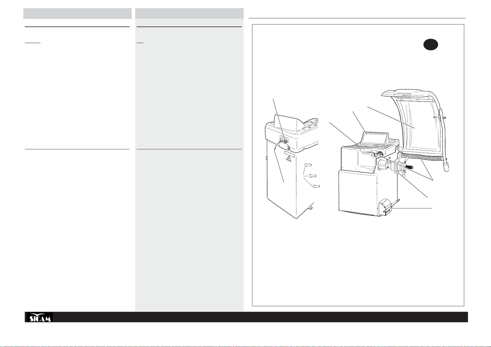
DISEGNO ILLUSTRATIVO DELLA MACCHINA
con indicazione delle principali parti componenti ai fini dell’uso
LEGENDA
A: INTERRUTTORE GENERALE
B: CAVO DI ALIMENTAZIONE
C: CRUSCOTTO PORTAPESI
D: PANNELLO COMANDI
E: CARTER PROTEZIONE RUOTA
F: FLANGIA
G. CALIBRI AUTOMATICI
H: PEDALE FRENO
I: SUPPORTO FLANGIA E ACCESSORI
L: ALIMENTAZIONE PNEUMATICA
ILLUSTRATIVE MACHINE DRA WING
indicating the main parts relevant to use
KEY
A: MAIN SWITCH
B: POWER SUPPLY CABLE
C: WEIGHT HOLDER PANEL
D: CONTROL PANEL
E: WHEEL GUARD COVER
F: ADAPTER
G. AUTOMATIC GAUGES
H: BRAKE PEDAL
I: ADAPTER AND ACCESSORIES SUPPORT
L: COMPRESSED AIR SUPPLY
A
C
D
SBM 155
E
CARATTERISTICHE TECNICHE
» Equilibratrice elettronica a lancio unico e ciclo completamente
automatico: avviamento, misura, frenata; viene misurato lo squilibrio
dinamico ed i valori del peso e della posizione dei due piani di
correzione vengono visualizzati contemporaneamente su doppio dis-
play.
» Pannello comandi: l’impostazione a progressione delle tre misure ruota
e del programma di equilibratura unitamente ai tasti dedicati per la
separazione dei pesi e l’impostazione delle misure in mm permettono
un utilizzo semplice e rapido della macchina.
» Programmi di equilibratura: dinamica standard, 5 programmi ALU, 3
programmi statica (per ruote da motocicletta o autovettura con
l’applicazione di contrappesi adesivi o a molletta); due programmi
ALU speciali per ruote PAX; opzione di separazione dei pesi; programma di ottimizzazione squilibrio statico.
» Calibri *AUTOMATICI per l’impostazione automatica delle misure della
ruota.
» Calibro *ALUDATA per il posizionamento del peso nei cerchi in
alluminio.
» Funzioni di autodiagnosi e autotaratura che rendono estremamente
semplice la manutenzione.
» Freno di stazionamento per il bloccaggio della ruota durante le
operazioni di posizionamento dei contrappesi.
» Carter di protezione ruota: di ingombro estremamente limitato, permette
l’introduzione di ruote aventi un diametro esterno massimo di 820 mm.
» Dispositivi di sicurezza standard: tasto STOP per l’arresto del motore
in condizioni di emergenza; carter di protezione ruota: quando il carter
è aperto, un dispositivo elettrico impedisce l’avviamento della
macchina.
» Possibilità di memorizzare dati di lavoro di due utenti che lavorano
contemporaneamente.
*In funzione del modello la macchina è dotata di questi dispositivi.
TECHNICAL CHARACTERISTICS
» Electronic wheel balancer with fully-automatic single cycle: start-up,
measuring, braking; the dynamic imbalance is measured and the weight
and position of the two correction planes are displayed simultaneously
on the double display.
» Control panel: the progressive setting of the three wheel sizes and the
wheel balancing program together with the dedicated keys for weight
separation and measurement setting in mm makes the machine quick
and easy to use.
» Balancing programs: standard dynamic, 5 ALU programs, 3 static pro-
grams (for motorcycle wheels or for vehicles needing adhesive or
clipped counterweights); two special ALU programs for PAX wheels;
weight separation option; static imbalance optimization program.
»*AUTOMATIC gauges for automatically setting the wheel measure-
ments.
» *ALUDATA gauge for positioning weights on aluminum rims.
» Functions of self-diagnosis and self-calibration for extremely simple
maintenance.
» Holding brake for locking the wheel during the counterweight position-
ing operations.
» Wheel guard: very small bulk permitting the insertion of wheels of up
to 820 mm external diameter.
» Standard safety devices: STOP button for emergency motor shutdown;
wheel guard; when the guard is up, an electrical device prevents the
motor from being started up.
» Option of memorizing operating data for two users working simulta-
neously.
*The presence of these devices depends on the machine model.
I
G
B
F
H
COD. 655632 Rev.0
4
Page 5
FRANÇAIS
DEUTSCH
ESPAÑOL
РУССКИЙ
PLAN ILLUSTRATIF DE LA MACHINE
avec l’indication des principales parties composantes pour
l’utilisation
LEGENDE
A: INTERRUPTEUR GENERAL
B: CABLE DE L’ALIMENTATION
C: TABLEAU PORTE-MASSES
D: PANNEAU DE COMMANDES
E: PROTECTION DE LA ROUE
F: PLATEAU
G. PIGES AUTOMATIQUES
H: PEDALE DU FREIN
I: SUPPORT DU PLATEAU ET ACCESSOIRES
L: ALIMENTATION PNEUMATIQUE
TECHNISCHE DARSTELLUNG DER MASCHINE
mit Angabe der zur Verwendung dienenden Hauptbestandteile
LEGENDE
A: HAUPTSCHALTER
B: NETZKABEL
C: ARBEITSPLATTE MIT GEWICHTEBEHÄLTERN
D: STEUERTAFEL
E: RADSCHUTZABDECKUNG
F: FLANSCH
G. AUTOMATISCHE KALIBER
H: BREMSPEDAL
I: FLANSCH- UND ZUBEHÖRHALTERUNG
L: WARTUNGSEINHEIT MIT DRUCKLUFTANSCHLUSS
ESQUEMA ILUSTRATIVO DE LA MÁQUINA
con indicación de las principales partes componentes para el uso
LEYENDA
A: INTERRUPTOR GENERAL
B: CABLE DE ALIMENTACIÓN
C: TABLERO PORTAPESOS
D: PANEL DE MANDOS
E: CÁRTER DE PROTECCIÓN DE LA RUEDA
F: BRIDA
G: CALIBRES AUTOMÁTICOS
H: PEDAL DE FRENO
I: SOPORTE DE LA BRIDA Y ACCESORIOS
L: ALIMENTACIÓN NEUMÁTICA
ИЛЛЮСТРАТИВНЫЙ ЧЕРТЕЖ СТАНКА
с указанием основных составляющих частей используемых при
эксплуатации
ОБОЗНАЧЕНИЯ
A: ОБЩИЙ ВЫКЛЮЧАТЕЛЬ
B: КАБЕЛЬ ПИТАНИЯ
C: ЩИТОК С ГНЕЗДАМИ ДЛЯ ХРАНЕНИЯ ГРУЗИКОВ
D: ПУЛЬТ УПРАВЛЕНИЯ
E: ЗАЩИТНЫЙ КОЖУХ КОЛЕСА
F: ФЛАНЕЦ
G. АВТОМАТИЧЕСКИЕ МЕРНЫЕ ЛИНЕЙКИ
H: ПЕДАЛЬ ТОРМОЗА
I: ОПОРА ДЛЯ ФЛАНЦА И ПРИНАДЛЕЖНОСТЕЙ
L: ПНЕВМАТИЧЕСКОЕ ПИТАНИЕ
CARACTERISTIQUES TECHNIQUES
» Equilibreuse électronique à un seul lancer et cycle complètement
automatique: mise en marche, mesure, freinée; le balourd dynamique
est mesuré et les valeurs de la masse et de la position des deux plans
de correction sont affichés simultanément sur un double afficheur.
» Panneau de commandes: l’introduction par progression des trois
mesures de la roue et du programme d’équilibrage avec les touches
dédiées pour la séparation des masses et l’introduction des mesures
en mm permettent une utilisation simple et rapide de la machine.
» Programmes d’équilibrage: dynamique standard, 5 programmes ALU,
3 programmes statique (pour des roues de motocyclette ou de tourisme
avec l’application de masses collantes ou à pince); deux programmes
ALU spéciaux pour les roues PAX; option de séparation des masses;
programme d’optimisation du balourd statique.
» Piges *AUTOMATIQUES pour l’introduction automatique des mesures
de la roue.
» Piges *ALUDATA pour le positionnement de la masse dans les jantes
en aluminium.
» Fonctions d’autodiagnostic et d’autotarage qui rendent l’entretien
extrêmement simple.
» Frein de stationnement pour le blocage de la roue pendant les opérations
de positionnement des masses.
» Carter de protection de la roue: avec un encombrement extrêmement
limité, il permet l’introduction de roues ayant un diamètre extérieur
maxi de 820 mm.
» Dispositifs de sécurité standard: touche STOP pour l’arrêt du moteur
dans des situations d’urgence; carter de protection de la roue: quand
le carter est ouvert, un dispositif électrique empêche la mise en marche
de la machine.
» Possibilité de mémoriser les données de travail de deux utilisateurs
qui travaillent simultanément.
* La machine est munie de ces dispositifs, selon le modèle.
TECHNISCHE EIGENSCHAFTEN
» Elektronische Auswuchtmaschine mit einmaligem Start und
vollautomatischem Start-, Mess- und Bremszyklus: Die dynamische
Unwucht wird zusammen mit den Gewichtswerten und der Position
der beiden Korrektionsebenen werden gleichzeitig auf dem doppelten
Display angezeigt.
» Steuertafel: Die progressive Einstellung der 3 Radmaße und des
Auswuchtprogramms zusammen mit den Tasten für die
Gewichtetrennung und die Vorgabe der Masse in mm ermöglichen
eine einfache und schnelle Bedienung der Maschine.
» Auswuchtprogramme: Dynamische Standardauswuchtprogramme, 5
ALU-Programme, 3 statische Programme (für Motorrad- oder
Kraftfahrzeugräder mit Haft- oder Klemmgewichten), zwei spezielle
ALU-Programme für PAX-Räder, Möglichkeit der Gewichtetrennung,
statisches Auswuchtoptimierungsprogramm.
» AUTOMATISCHE Kaliber* für die automatische Einstellung der
Radmaße.
» Kaliber *ALUDATA für die Gewichtspositionierung an Alufelgen.
» Funktionen der Selbstdiagnose und Selbsteichung, die die Wartung
außerordentlich einfach gestalten.
» Standbremse zum Blockieren des Rads beim Anbringen der
Gegengewichte.
» Radschutzabdeckung: besonders Platz sparend, ermöglicht das
Einführen der Räder mit einem Außendurchmesser von maximal 820
mm.
» Standardsicherheitsvorrichtungen: STOP-Taste zum Halt des Motors
unter Notbedingungen; Radschutzabdeckung: bei geöffneter
Schutzabdeckung verhindert eine elektrische Vorrichtung den
Maschinenstart.
» Möglichkeit des Speicherns der Arbeitsparameter zweier gleichzeitig
tätiger Bediener.
* Ausstattung je nach Modell.
CARACTERÍSTICAS TÉCNICAS
» Equilibradora electrónica de lanzamiento único y ciclo completamente
automático: arranque, medición, frenado; mide el desequilibrio dinámico
y visualiza simultáneamente en doble pantalla los valores de peso y
de posición de los dos planos de corrección.
» Panel de mandos: la programación en progresión de las tres medidas
de la rueda y del programa de equilibrado junto con las teclas dedicadas
para la separación de los pesos y la introducción de las medidas en
mm permiten un uso simple y rápido de la máquina.
» Programas de equilibrado: dinámico estándar, 5 programas ALU, 3
programas de equilibrado estático (para ruedas de motocicleta o
automóvil con la aplicación de contrapesos adhesivos o de pinza);
dos programas ALU especiales para ruedas PAX; opción de separación
de los pesos; programa de optimización del desequilibrio estático.
» Calibres *AUTOMÁTICOS para la introducción automática de las
medidas de la rueda.
» Calibre *ALUDATA para la colocación del peso en las llantas de aluminio.
» Funciones de autodiagnóstico y autorregulación que hacen
extremadamente simple el mantenimiento.
» Freno de estacionamiento para el bloqueo de la rueda durante las
operaciones de colocación de los contrapesos.
» Cárter de protección de la rueda: su reducido tamaño permite introducir
ruedas con un diámetro externo máximo de 820 mm.
» Dispositivos de seguridad estándar: tecla STOP para la parada del
motor en condiciones de emergencia; cárter de protección de la rueda:
cuando cárter está abierto, un dispositivo eléctrico impide la puesta
en marcha de la máquina.
» Posibilidad de memorizar los datos de trabajo de dos usuarios
simultáneos.
* La máquina estará dotada o no de estos dispositivos en función del
modelo.
ТЕХНИЧЕСКИЕ ХАРАКТЕРИСТИКИ
» Электронный балансировочный станок выполняет работу
одним измерительным запуском в автоматическом режиме:
разгон, измерение, торможение. Одновременно производит
измерение динамического дисбаланса колеса по двум
плоскостям с высвечиванием значений веса грузика и его
положения на двойном дисплее.
» Пульт управления: значения трех размеров колеса и выбор
программы балансировки осуществляется
последовательным нажатием кнопки, которая совместно с
кнопками предназначенными для операции разделения веса и
введения размеров в миллиметрах, дает возможность легко
и быстро использовать станок.
» Программы балансировки: стандартная динамическая, 5
программ ALU, 3 статические программы (для колес
мотоцикла или легкового автомобиля с установкой
самоклеющихся грузиков или грузиков со скобой); две
специальные программы ALU для колес PAX; возможность
выбора программы разделения грузиков; программа
оптимизации статического дисбаланса.
» АВТОМАТИЧЕСКИЕ мерные линейки* для автоматического
введения размеров колеса.
» Система мерных линеек * ALUDATA для установки грузиков
на дисках из алюминия.
» Система самодиагностики и самокалибровки делает крайне
простым техническое обслуживание.
» Тормоз блокировки: для блокировки колеса во время
операции установки грузиков.
» Защитный кожух колеса: с экстремально ограниченными
габаритными размерами позволяет производить
балансировку колес, максимальный внешний диаметр которых
не превышает 820 мм;
» Стандартное устройство безопасности: кнопка STOP для
останова двигателя в аварийной ситуации; защитный кожух
колеса: при открытом кожухе защиты колеса специальное
устройство не позволяет запуск машины.
» Возможность вводить в память рабочие данные двух
пользователей работающих одновременно
* станок снабжен этими устройствами в зависимости от модели.
COD. 655632 Rev.0
5
Page 6
ITALIANO
ENGLISH
DATI TECNICI
3
4
2
DIMENSIONI
Altezza Max (con carter aperto)............................................... 1800mm
Profondità (con carter aperto)................................................ 1260mm
Larghezza (senza flangia) ....................................................... 860mm
Larghezza (con flangia) .......................................................... 900 mm
PESO
Peso Netto ................................................................................. 158 kg
Peso Lordo ................................................................................ 187 Kg
ALIMENTAZIONE ELETTRICA
Alimentazione (3 modelli)115V 1~ 60Hz / 230V 1~ 50Hz / 230V 1~ 60Hz
Potenza ..................................................................................... 0.7 kW
Fasi .................................................................................................... 1~
Protezione .................................................................................... IP 22
Vel. di equilibratura ...................... 190 rpm a 50Hz / 230 rpm a 60Hz
Risoluzione lettura squilibrio ............................... 1/5 g (0.01/0.25 oz)
Rumorosità ............................................................................... < 75 db
TECHNICAL DA T A
DIMENSIONS
Max height (with cover open).................................................. 1800mm
Depth (with cover open) ........................................................ 1260mm
Width (without adapter) ........................................................... 860mm
Width (with adapter) ................................................................. 900mm
WEIGHT
Net Weight ................................................................................. 158 kg
Gross Weight ............................................................................ 187 Kg
ELECTRICAL SUPPLY
Power supply (3 models)115V 1~ 60Hz / 230V 1~ 50Hz / 230V 1~ 60Hz
Power ........................................................................................ 0.7 kW
Phases .............................................................................................. 1~
Protection ..................................................................................... IP 22
Balancing speed ......................... 190 rpm at 50Hz / 230 rpm at 60Hz
Imbalance reading resolution ............................... 1/5 g (0.01/0.25 oz)
Noise level ............................................................................... < 7 5 db
SBM 155
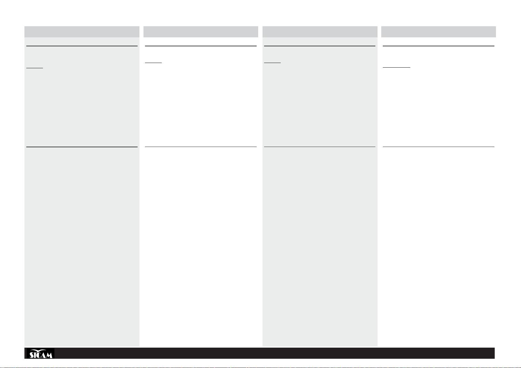
DATI DI TARGA
REGISTRATION PLATE DAT A
DONNEES DE PLAQUE
ANGABEN AUF DEM MA TRIKELSCHILD
DATOS DE CHAPA
ДАННЫЕ ТАБЛИчКИ
1
2
3
GAMMA DI APPLICAZIONI
SBM 155 è predisposta per equilibrare ruote d’autovettura fino ad un peso
di 70kg e ruote da motociclo fino ad un peso di 20kg. La capacità operativa
della macchina è la seguente:
Larghezza cerchione .................................................................. 1" - 20"
Diametro cerchione ................................................................ 10" - 26"
Diametro max ruota ................................................................. 900mm
Peso max. ruota ......................................................................... 70 kg
N.B.: Le misure minime e massime sopra elencate si riferiscono allo squilibrio
dinamico nei due piani di compensazione o al solo squilibrio statico. Lo
squilibrio viene indicato in grammi con 3 cifre digitali. Se si preferisce
l’indicazione in once al posto dei grammi, la trasformazione viene effettuata
tramite il pannello comandi (vedi paragrafo “configurazione equilibratrice”).
min/max
ACCESSORI IN DOTAZIONE (Fig.3)
LEGENDA
1. Pinza Contrappesi
2. Caliibro Misurazione Larghezza
3. Adattatore Universale
4. Calibro speciale per cerchi in alluminio
ACCESSORI A RICHIEST A (Fig.4)
LEGENDA
1. Flangia 3/4/5 Fori con Dadi Standard
2. Dadi Rapidi
3. Flangia per Ruote Moto
4. Distanziale
5. III° e IV° Cono
6. Anello Centraggio Renault - Citroen - Peugeot
RANGE OF APPLICA TIONS
SBM 155 is designed for balancing car wheels up to a weight of 70kg and
motorcycle wheels up to a weight of 20kg. The operating capacity of the
machine is the following:
Rim width ................................................................................. 1" - 20"
Rim diameter .......................................................................... 10" - 26"
Max. wheel diameter ............................................................... 900mm
Max wheel weight ...................................................................... 70 kg
N.B.: The minimum and maximum figures given above refer to the dynamic imbalance on the two compensating planes, or to static imbalance
alone. Imbalance is indicated in grams in three digital figures . If readings
in ounces are preferred to grams,the transformation can be programmed
(see “Wheel Balancer Configuration” section).
min/max
ACCESSORIES PROVIDED (Fig.3)
KEY
1. Counterweight pliers
2. Width measuring gauge
3. Universal adapter
4. Special gauge for aluminium rims
ACCESSORIES ON REQUEST (Fig.4)
KEY
1. 3/4/5 Hole adapter with standard nuts
2. Quick release nuts
3. Motorcycle wheel adapter
4. Spacer
5. 3rd and 4th Cone
6. Centring rings for Renault - Citroën - Peugeot
4
1
2
6
3
5
4
COD. 655632 Rev.0
6
Page 7
FRANÇAIS
DEUTSCH
ESPAÑOL
РУССКИЙ
DONNEES TECHNIQUES
DIMENSIONS
Hauteur Maxi (avec carter ouvert) ........................................... 1800mm
Profondeur (avec carter ouvert) ............................................... 1250mm
Largeur (sans plateau) ............................................................... 850mm
Largeur (avec plateau) ............................................................... 900mm
POIDS
Poids Net ................................................................................... 158 kg
Poids Brut .................................................................................. 187 Kg
ALIMENTATION ELECTRIQUE
Alimentation (3 modèles)115V 1~ 60Hz / 230V 1~ 50Hz / 230V 1~ 60Hz
Puissance ................................................................................. 0.7 kW
Phases .............................................................................................. 1~
Protection ..................................................................................... IP 22
Vitesse d’équilibrage ..................... 190 rpm à 50Hz / 230 rpm à 60Hz
Résolution lecture du balourd .............................. 1/5 g (0.01/0.25 oz)
Niveau de bruit ......................................................................... < 75 db
TECHNISCHE DATEN
ABMESSUNGEN
Max. Höhe (bei offener Schutzabdeckung).............................. 1800mm
Tiefe (bei offener Schutzabdeckung) ....................................... 1250mm
Breite (ohne Flansch) .............................................................. 860mm
Breite (mit Flansch) ................................................................. 900mm
GEWICHT
Nettogewicht ............................................................................. 158 kg
Bruttogewicht............................................................................ 187 Kg
STROMVERSORGUNG
Speisung (3 Modelle) 115V 1~ 60Hz / 230V 1~ 50Hz / 230V 1~ 60Hz
Leistung..................................................................................... 0.7 kW
Phasen .............................................................................................. 1~
Schutz .......................................................................................... I P 22
Auswuchtgeschwindigkeit ...... 190 rpm mit 50Hz-230 rpm mit 60Hz
Auflösung Unwuchtsablesung ............................. 1/5 g (0.01/0.25 oz)
Lärm .......................................................................................... < 75 db
DATOS TÉCNICOS
MEDIDAS
Altura Máx (con cárter abierto) ............................................. 1800mm
Profundidad (con cárter abierto)............................................ 1250mm
Anchura (sin brida) ................................................................... 860mm
Anchura (con brida).................................................................. 900mm
PESO
Peso neto .................................................................................. 158 kg
Peso bruto ................................................................................. 187 Kg
ALIMENTACIÓN ELÉCTRICA
Alimentación (3 modelos)115V 1~ 60Hz / 230V 1~ 50Hz / 230V 1~ 60Hz
Potencia .................................................................................... 0.7 kW
Fases ................................................................................................1~
Protección .................................................................................... IP 22
Vel. de equilibrado ............. 190 g/min a 50Hz / 230 g/min a 60Hz
Resolución lectura desequilibrio ......................... 1/5 g (0.01/0.25 oz)
Ruido ........................................................................................ < 75 db
ТЕХНИЧЕСКИЕ ДАННЫЕ
РАЗМЕРЫ
Максимальная высота (при открытом кожухе) ........................ 1800мм
Глубина (при открытом кожухе) ................................................. 1250мм
Ширина (без фланца) .............................................................. 860мм
Ширина (с фланцем) ............................................................... 900мм
ÂÅÑ
Вес нетто ........................................................................................ 158 кг
Вес брутто ..................................................................................... 187 кг
ЭЛЕКТРОДВИГАТЕЛЬ
Питание (три модели)115В 1~ 60Гц / 230В 1~ 50 Гц / 230В 1~ 60 Гц
Мощность................................................................................... 0.7 кВт
Ôàçû ...................................................................................................... 1 ~
Защита .............................................................................................. IP 22
Скорость балансировки .... 190 об/мин при 50Гц / 230 об/мин при 60Гц
Точность балансировки ............................ 1/5 г (0.01/0.25 унции)
Óð î âåí ü ø óìà .......................................................................... < 75 äÁ
GAMME D’APPLICATIONS
SBM 155 est prévue pour équilibrer des roues de voiture jusqu’à un poids
de 70kg et des roues de moto jusqu’à un poids de 20kg. La capacité
opérationnelle de la machine est la suivante:
Largeur de la jante ................................................................... 1" - 20"
Diamètre de la jante............................................................... 10" - 26"
Diamètre maxi de la roue ........................................................ 900mm
Poids maxi de la roue ................................................................ 70 kg
Nota: Les mesures minimum et maximum énumérées ci-dessus se réfèrent
au balourd dynamique des deux plans de compensation ou uniquement au
balourd statique. Le balourd est indiqué en grammes par 3 chiffres digitaux.
Si l’on préfère l’indication en onces à la place des grammes, la transformation est effectuée sur le panneau de commandes (voire paragraphe
“configuration équilibreuse”).
min/max
ACCESSOIRES EN DOTA TION (Fig.3)
LEGENDE
1. Pince à Masses
2. Pige de Mesure de la Largeur
3. Adaptateur Universel
4. Pige spéciale pour des jantes en alu
ACCESSOIRES SUR DEMANDE (Fig.4)
LEGENDE
1. Plateau à 3/4/5 trous avec écrous standard
2. Ecrous rapides
3. Plateau pour les roues de moto
4. Entretoise
5. IIIe et IVe Cône
6. Bague de centrage Renault - Citroën - Peugeot
ANWENDUNGSBEREICH
SBM 155 ist vorgesehen für das Auswuchten von Kraftfahrzeugrädern bis
zu einem Gewicht von 70 Kg und Motorradrädern bis zu einem Gewicht
von 20 Kg. Die Arbeitskapazität der Maschine ist folgende:
Felgenbreite ............................................................................. 1" - 20"
Felgendurchmesser............................................................... 10" - 26"
Max. Raddurchmesser ............................................................ 900mm
Max. Radgewicht. ...................................................................... 70 kg
Anm.: Die o.a. Mindest- und Höchstmasse beziehen sich auf die
dynamische Unwucht der beiden Kompensationsebenen oder lediglich
auf die statische Unwucht. Die Unwucht wird in Gramm mit 3 digitalen
Ziffern angegeben. Zieht man die Angabe in Once der Angabe in Gramm
vor , führt der Programmierer die Umformung aus. (s. S.21 und folgende).
min/max
MITGELIEFERTES ZUBEHÖR (Abb.3)
LEGENDE
1. Gegengewichtzange
2. Kaliber Breitenmessung
3. Universeller Adapter
4. Spezialkaliber für Aluminiumfelgen
AUF ANFRAGE ERHÄL TLICHES ZUBEHÖR (Abb.4)
LEGENDE
1. Flansch 3/4/5 Löcher mit Standardmutterschrauben
2. Schnellmuttern
3. Flansch für Motorradräder
4. Entfernungsstück
5. III° e IV° Kegel
6. Zentrierring Renault - Citroën - Peugeot
GAMA DE APLICACIONES
La SBM 155 ha sido preajustada para equilibrar ruedas de automóvil con
un peso de hasta 70kg y ruedas de motocicleta con un peso de hasta
20kg. La capacidad operativa de la máquina es la siguiente:
Anchura llanta .......................................................................... 1" - 20"
Diámetro llanta ....................................................................... 10" - 26"
Diámetro máx rueda ................................................................ 900mm
Peso máx. rueda ........................................................................ 7 0 kg
Nota: Las medidas mínimas y máximas señaladas anteriormente se
refieren al desequilibrio dinámico en los dos planos de compensación o
solo al desequilibrio estático. El desequilibrio viene indicado en gramos
con 3 cifras digitales. SI se prefiere la indicación en onzas en lugar de los
gramos, la transformación se efectúa mediante el panel de mandos (ver
apartado “Configuración de la equilibradora”).
min/max
ACCESORIOS EN DOTACIÓN (Fig.3)
LEYENDA
1. Pinza Contrapesos
2. Calibre Medición Anchura
3. Adaptador Universal
4. Calibre especial para llantas de aluminio
ACCESORIOS BAJO PEDIDO (Fig.4)
LEYENDA
1. Brida 3/4/5 Agujeros con Dados Estándar
2. Dados Rápidos
3. Brida para Ruedas Moto
4. Distancial
5. III° y IV° Cono
6. Anillo Centrado Renault - Citroën - Peugeot
ОБЛАСТЬ ПРИМЕНЕНИЯ
SBM 155 предрасположены для балансировки колес легковых
автомобилей весом до 70кг и колес мотоциклов весом до 20кг.
Станки имеют следующую рабочую способность:
Ширина обода ............................................................................. 1" - 20"
Диаметр обода........................................................................ 10" - 26"
Макс. Диаметр колеса ............................................................ 900мм
Максимальный вес колеса ......................................................... 70 кг
Вышеперечисленные минимальные и максимальные значения
относятся к динамическому дисбалансу по двум
компенсационным плоскостям или только к статическому
дисбалансу. Дисбаланс указывается в граммах 3-мя цифрами.
Если предпочитаете иметь данные в унциях вместо граммов,
замена может быть проведена через пульт управления (параграф
“Конфигурация балансировочного станка“)
Ìèí/ìàêñ
КОМПЛЕКТУЮЩЕЕ ОБОРУДОВАНИЕ (рис.3)
Обозначения
1. Клещи для грузиков
2. Штангенциркуль для измерения ширины
3. Универсальные адаптеры.
4 Специальная мерная линейка для обода из алюминия
ОБОРУДОВАНИЕ, ПОСТАВЛЯЕМОЕ ПО ЗАКАЗУ (рис.4)
Обозначения
1. Фланец с 3/4/5 отверстиями и стандартными гайками
2. Быстро завинчивающиеся гайки -
3. Фланец для колес мотоцикла
4. Закладная деталь
5. III-ий и IV-ый Конус
6. Центровочное кольцо Рено – Ситроен - Пежо
COD. 655632 Rev.0
7
Page 8
ITALIANO
ENGLISH
5
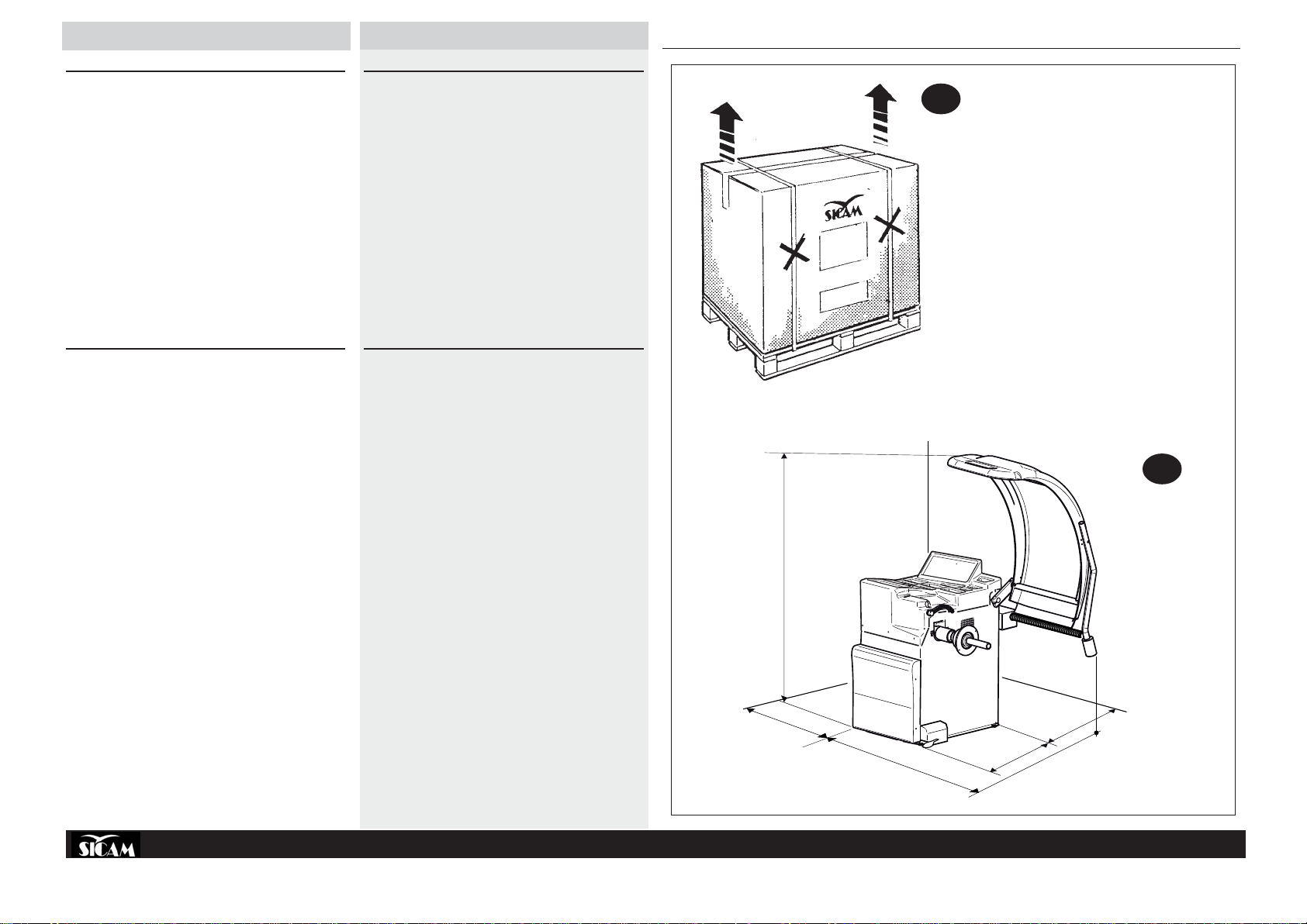
DISIMBALLO
6
SBM 155
UNPACKING
» Dopo avere tolto l’imballaggio (ved. fig.5) assicurarsi del’integrità della
macchina controllando che non vi siano parti visibilmente danneggiate.
In caso di dubbio non utilizzare la macchina e rivolgersi a personale
professionalmente qualificato e/o al proprio rivenditore.
» Gli elementi dell’imballaggio (sacchetti di plastica, pluriball, polietilene,
chiodi, graffette, legni ecc.) non devono essere lasciati alla portata dei
bambini in quanto potenziali fonti di pericolo.
Riporre i suddetti materiali negli appositi luoghi di raccolta se inquinanti
o non biodegradabili.
» La scatola contenente gli accessori in dotazione è inserita nell’imballo
della macchina.
COLLOCAMENTO
» L’equilibratrice deve essere posta su un solido pavimento di cemento o
simile.
Un vuoto sottostante può dare luogo ad imprecisione nelle misure degli
squilibri.
» DIMENSIONI D’INGOMBRO:
1800mm x 1250mm x 1260mm
» DISTANZE DI SICUREZZA:
Per un utilizzo sicuro ed ergonomico della macchina è consigliabile
collocarla ad una distanza minima di 500mm dalle pareti circostanti (fig.
6).
» PRESCRIZIONI DI FISSAGGIO:
Il basamento della macchina è provvisto di 3 fori per il fissaggio al
pavimento. Un buon fissaggio è indispensabile per avere indicazioni
precise e costanti.
» After removing the packing (strapping, seals, cardboard, and the pallet,
see fig. 5) check the machine for missing or damaged parts. If in doubt
do not use the machine and refer to professionally qualified personnel
and/or to the seller.
» The packing materials (plastic bags, pluriball, polythene, nails, staples,
timber, etc.) must not be left within reach of children since these are
potentially dangerous.
Deposit the above mentioned materials at the relevant collection points if
they are pollutants or are non biodegradable.
» The box containing the accessories provided is contained in the pack-
ing of the machine.
LOCATION
» The wheel balancer must be located on a solid floor in concrete or similar
material. An underlying cavity could cause imprecise imbalance readings.
» OVERALL DIMENSIONS:
1800mm x 1250mm x 1260mm
» SAFE DISTANCE:
For the safe and ergonomic use of the machine it is advisable to locate it
a minimum of 500 mm from the surrounding walls (fig. 6).
» FIXING INSTRUCTIONS:
The machine base has 3 holes for fixing to the floor. This is essential to
ensure accurate and consistent readings.
1800
500
1260
COD. 655632 Rev.0
900
500
8
Page 9

FRANÇAIS
DEUTSCH
ESPAÑOL
РУССКИЙ
DEBALLAGE
ENTFERNEN DER VERPACKUNG
DESEMBALAJE
РАСПАКОВКА
» Après avoir ôté l’emballage (voir fig.5) s’assurer de l’intégrité de la ma-
chine en contrôlant qu’il n’y ait pas de parties visiblement endommagées.
Dans le doute ne pas utiliser la machine et s’adresser à un
professionnel qualifié et/ou à son propre revendeur.
» Les éléments de l’emballage (sachets en plastique, pluriball, polyéthylène,
clous, agrafes, bois etc.) ne doivent pas être laissés à la portée des
enfants car ils représentent des sources de danger potentielles.
Déposer les matériels susdits dans les lieux de ramassage prévus s’ils
sont polluants ou non biodégradables.
» La boîte contenant les accessoires en dotation se trouve à l’intérieur
de l’emballage de la machine.
MISE EN PLACE
» L’équilibreuse doit être placée sur un sol solide en ciment ou similaire.
Un vide sousjacent peut donner lieu à des imprécisions dans les mesures
des balourds.
» DIMENSIONS D’ENCOMBREMENT:
1800 mm x 1250 mm x 1260 mm
» DISTANCES DE SECURITE:
Pour une utilisation de la machine sûre et ergonomique il est conseillé
de la placer à une distance de 500 mm minimum des murs environnants
(fig. 6).
» FIXATION:
La base de la machine est munie de 3 trous pour la fixation au sol.
Une bonne fixation est indispensable pour obtenir des indications précises
et constantes.
» Überprüfen Sie nach dem Entfernen der Verpackung (s. Abb 5) die
Vollständigkeit und Unversehrtheit der Maschine. Überzeugen Sie sich,
dass keine Teile sichtbar beschädigt sind.
Im Zweifelsfall die Maschine nicht benutzen und sich an fachlich
qualifiziertes Personal und/oder an den Händler wenden
» Die Verpackungsmaterialien (Plastiktüten, Pluriball, Polyethylen,
Nägel, Klammern, Holzteile usw.) für Kinder unerreichbar aufbewahren,
da sie eine mögliche Gefahrenquelle darstellen. Die o.g. Materialien
in die vorgesehenen Sammelstellen bringen, falls sie
umweltverschmutzend oder biologisch nicht abbaubar sind.
» Die Schachtel mit dem Standardzubehör befindet sich im Inneren der
Maschinenverpackung.
AUFSTELLEN DER MASCHINE
» Die Auswuchtmaschine muss auf einen soliden Boden aus Zement
oder ähnlichem Material gestellt werden.
Unebenheiten im Boden können zu Ungenauigkeiten bei der
Unwuchtmessung führen.
» ABMESSUNGEN:
1800mm x 1250mm x 1260mm
» SICHERHEITSABSTÄNDE:
Für eine sichere und ergonomische Anwendung der Maschine empfiehlt
es sich, diese mit einem Mindestabstand von 500mm von den
umliegenden Wänden entfernt aufzustellen (Abb 6).
» HINWEISE FÜR DIE BEFESTIGUNG:
Im Maschinenboden befinden sich drei Bohrungen für die Befestigung
am Untergrund. Eine gute Befestigung ist unerlässlich, um genaue und
konstante Angaben zu gewährleisten.
» Después de haber retirado el embalaje (ver fig.5) asegurarse de la
integridad de la máquina controlando que no haya partes visiblemente
dañadas. En caso de duda no utilizar la máquina y dirigirse a per-
sonal profesionalmente cualificado y/o al propio vendedor.
» Los elementos del embalaje (bolsas de plástico, pluriball, polietileno,
clavos, grapas, maderas etc.) no se deben dejar al alcance de los niños
ya que son potenciales fuentes de peligro.
Depositar dichos materiales en los lugares especiales de recogida si
son contaminantes o no biodegradables.
» La caja que contiene los accesorios en dotación se encuentra dentro
del embalaje de la máquina.
COLOCACIÓN
» Se debe colocar la equilibradora sobre un suelo sólido de cemento o
similar.
Un vacío en la parte inferior puede dar lugar a imprecisiones en las
medidas de los desequilibrios.
» DIMENSIONES MÁXIMAS OCUPADAS:
1800mm x 1250mm x 1260mm
» DISTANCIA DE SEGURIDAD:
Para un uso seguro y ergonómico de la máquina es aconsejable colocarla
a una distancia mínima de 500mm de las paredes circunstantes (fig. 6).
» PRESCRIPCIONES DE FIJADO:
La parte inferior de la máquina está provista de 3 agujeros para la fijación
al suelo. Es indispensable una buena fijación para tener indicaciones
precisas y constantes.
» Удалив упаковку (бандажные полосы, пломбы, картон и поддон, как
это было указано на рис 5), необходимо убедится в сохранности
станка, визуально проверив отсутствие поврежденных частей. В
случае сомнения не использовать станок и обращаться к
квалифицированному персоналу и/или продавцу.
» Упаковка (полиэтиленовые пакеты, пенопластовый заполнитель,
пленка, гвозди, скрепки, деревянные детали и т.д.) не должны
находиться в пределах досягаемости детей, так как они являются
источниками опасности. Поместить вышеуказанные материалы в
соответствующие места сбора, если они могут загрязнить
окружающую среду или не подвержены биодеструкции.
» Коробка, где находятся поставляемые принадлежности, включена в
упаковку станка.
РАЗМЕЩЕНИЕ
» Балансировочный станок должен устанавливаться на жесткое
половое покрытие из бетона или сходных ему материалов.
Находящиеся под станком пустоты могут быть причиной неточности
в измерениях дисбаланса
» ГАБАРИТНЫЕ РАЗМЕРЫ:
1800ìì õ 1250ìì x 1260ìì
» БЕЗОПАСНОЕ РАССТОЯНИЕ:
Для безопасной и эргономической эксплуатации станка
рекомендуется размещать его на минимальном расстоянии 500 мм
от близлежащих стен (рис.6).
» УКАЗАНИЯ ПО КРЕПЛЕНИЮ:
Основание станка имеет 3 отверстия для крепления к полу. Для
получения точных и постоянных показаний станок должен быть
хорошо прикреплен.
COD. 655632 Rev.0
9
Page 10
ITALIANO
ENGLISH
8
INSTALLAZIONE
A
B
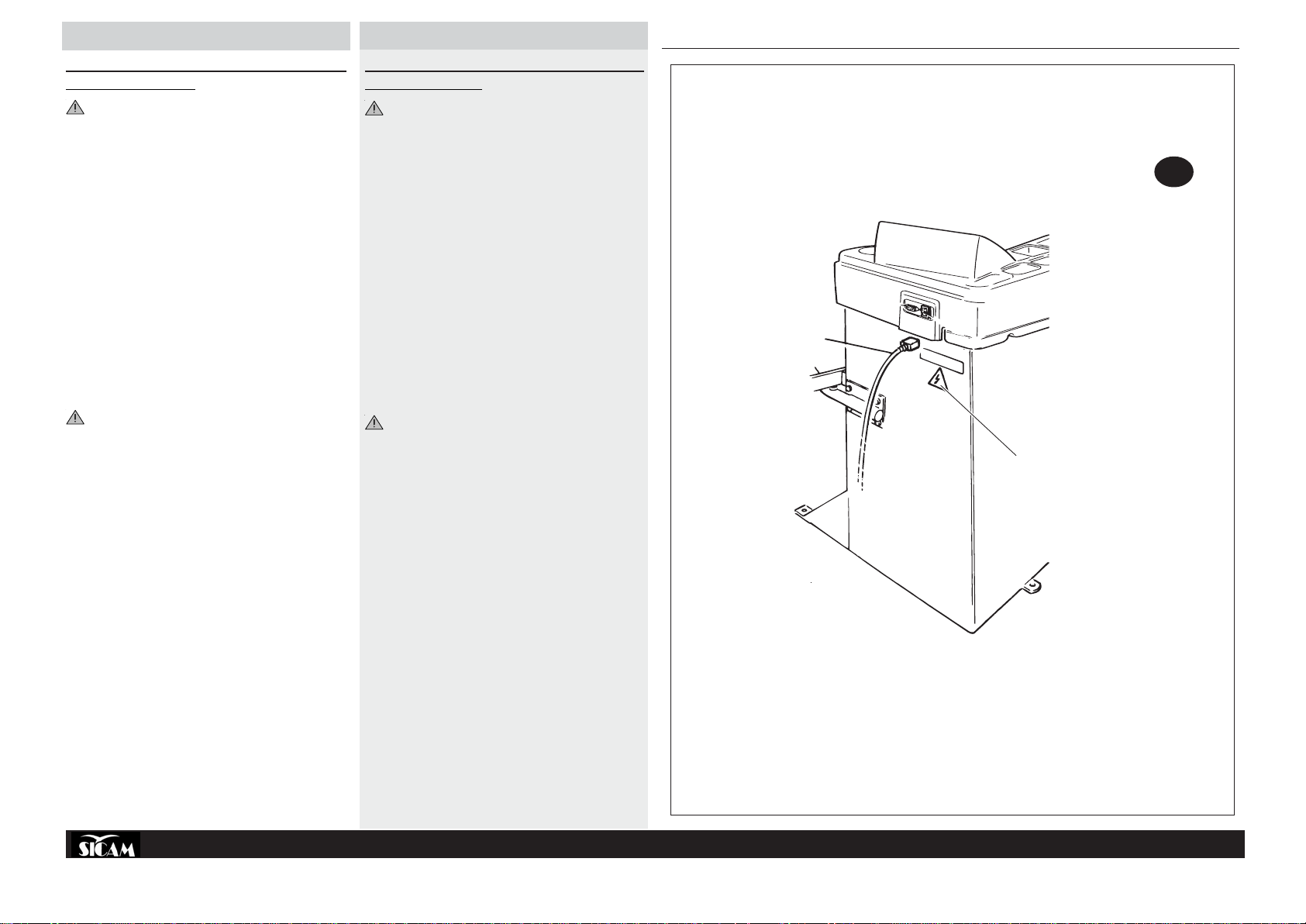
COLLEGAMENTO ELETTRICO
OGNI INTERVENTO SULL’IMPIANTO ELETTRICO, ANCHE DI
LIEVE ENTITÀ, DEVE ESSERE EFFETTUATO DA PERSONALE
PROFESSIONALMENTE QUALIFICATO !
» Controllare la conformità tra la tensione di linea e quella indicata sulla
targa della macchina.
» Collegare il cavo dell’alimentazione (fig.8)(A) a una spina conforme
alle norme Europee o alle norme del paese di destinazione della
macchina. La spina deve essere provvista obbligatoriamente del
contatto di terra.
» Verificare l’efficacia della messa a terra.
» La macchina deve essere allacciata alla rete tramite un sezionatore
onnipolare conforme alle norme Europee, con apertura dei contatti di
almeno 3mm.
» Effettuato il collegamento, e con la macchina inserita, la ruota montata
deve ruotare in senso orario, vista dal lato destro della macchina.
» Se la rotazione avviene nel senso sbagliato, sul monitor apparirà un
messaggio di errore.
» Nel caso in cui si verificasse un uso anormale della macchina, azionare
immediatamente l’interruttore generale e controllare il manuale di
istruzioni nella sezione ricerca guasti di pag.16).
INSTALLATION
ELECTRICAL CONNECTION
ANY WORK DONE ON THE ELECTRICAL SYSTEM, EVEN A
SIMPLE JOB, MUST ONLY BE DONE BY QUALIFIED PROFESSIONAL TECHNICIANS
» Check the mains voltage is conform to that indicated on the machine
plate.
» Connect the power cable (fig. 8)(A) to a plug conform to European
standards or to the standards of the country where the machine is
installed. The plug must be earthed.
» Check that it is a good earth.
» The machine must be connected to the mains with a unipolar discon-
necting switch conform to European standards, with a contact gap of
at least 3mm.
» After making the connection, and with the machine turned on, the
wheel mounted on the machine must turn clockwise when viewing the
machine from the right side.
» If the rotation is wrong, the following error message will appear on the
monitor.
» In the case of an anomaly on the machine, immediately turn the main
switch off and refer to the fault finding section of the instruction manual
page 17).
SBM 155
IL COSTRUTTORE DECLINA OGNI RESPONSABILITÀ PER LA
MANCATA OSSERVANZA DI DETTE PRESCRIZIONI.
Prestare sempre particolare attenzione ai SEGNALI DI SICUREZZA
rappresentati da appositi adesivi applicati sulla macchina.
Fig.8(B): etichetta scarica elettrica - cod. N.100789
Nel caso di smarrimento o deterioramento dell’etichetta adesiva si prega
di richiederla attraverso il relativo numero di codice, al servizio “parti di
ricambio” SICAM.
THE MANUFACTURER DECLINES ANY RESPONSIBILITY IN THE CASE
OF NON-OBSERVANCE OF THESE INSTRUCTIONS.
Always pay particular attention to SAFETY SIGNS which are repre-
sented by the relevant adhesives fixed on the machine.
Fig. 8(B): electrical discharge label - code N.100789
If the adhesive labels are lost or damaged, request a replacement from
SICAM “Spare Parts” Service, quoting the relevant code number.
COD. 655632 Rev.0
10
Page 11
FRANÇAIS
DEUTSCH
ESPAÑOL
РУССКИЙ
INSTALLATION
BRANCHEMENT ELECTRIQUE
TOUTE INTERVENTION SUR LE SYSTEME ELECTRIQUE, MEME
SI ELLE EST PEU IMPORTANTE, NE DOIT ETRE EFFECTUEE
QUE PAR DU PERSONNEL PROFESSIONNELLEMENT
QUALIFIE !
» Contrôler la conformité entre la tension de la ligne et celle indiquée sur
la plaquette de la machine.
» Brancher le câble de l’alimentation (fig.8)(A) à une fiche conforme aux
normes européennes ou aux normes du pays de destination de la
machine. La fiche doit obligatoirement être munie du contact de terre.
» Vérifier l’efficacité de la mise à terre.
» La machine doit être branchée au réseau à travers un sectionneur
omnipolaire conforme aux normes européennes, avec une ouverture
des contacts d’au moins 3mm.
» Après avoir effectué le branchement, et avec la machine branchée, la
roue doit tourner dans le sens des aiguilles d’une montre, vue du côté
droit de la machine.
» Si la rotation a lieu dans le sens contraire, un message d’erreur apparaîtra
à l’écran.
» Dans le cas d’une utilisation anormale de la machine, actionner
immédiatement l’interrupteur général et contrôler le manuel
d’instructions dans la partie recherche des anomalies de la pag.16).
LE CONSTRUCTEUR DECLINE TOUTE RESPONSABILITE POUR LA
NON OBSERVATION DES DITES PRESCRIPTIONS.
Faire toujours très attention aux SIGNALISATIONS DE SECURITE
représentées par des autocollants spéciaux appliqués sur la machine
Fig.8(B): étiquette de décharge électrique - code N.100789
Dans le cas de perte ou de détérioration de l’autocollant (l’étiquette
collante), vous êtes priés de le demander en spécifiant son numéro de
code, au service “pièces détachées” SICAM.
INSTALLATION
NETZANSCHLUSS
JEDER EINGRIFF, AUCH GERINGFÜGIGER ART, IN DIE
ELEKTRISCHE ANLAGE MUSS VON QUALIFIZIERTEM
FACHPERSONAL VORGENOMMEN WERDEN!
» Die Übereinstimmung der Versorgungsspannung mit der auf dem
Typenschild angegebenen Spannung überprüfen. Bei
Nichtübereinstimmung die Maschine NICHT in Betrieb nehmen!
» Das Anschlusskabel (Abb.8)(A) mit einem passenden Stecker
versehen, der den EU-Vorschriften oder denen des
Bestimmungslands des Geräts entspricht. Der Stecker muss
vorschriftsgemäß geerdet sein.
» Die Wirksamkeit der Erdung überprüfen
» Der Netzschutz des Anschlusses selbst ist kundenseitig mit den
europäischen Normen entsprechenden Schutzsicherungen oder mit
einem automatischen Schutzschalter bzw. einem Trennschalter mit
einer Kontaktöffnung von mindestens 3 mm durchzuführen.
» Nachdem der Anschluss erfolgt ist, schalten Sie die Maschine mit
dem Hauptschalter ein. Gehen Sie auf die Hauptseite des Menüs
(siehe Kap. Radauswuchtung). Nach Druck der OK-Taste muss sich
das montierte Rad – von der rechten Seite der Maschine gesehen – im
Uhrzeigersinn drehen. Die korrekte Drehrichtung ist durch einen Pfeil
auf dem Maschinengehäuse angezeigt.
» Bei Drehung in falscher Richtung bleibt die Maschine sofort stehen
und zeigt eine Fehlermeldung.
» Im Falle einer Fehlfunktion der Maschine, betätigen Sie sofort den
Hauptschalter und lesen Sie den Abschnitt Fehlfunktionen, mögliche
Ursachen und Abhilfe auf S.17der Gebrauchsanweisung.
DIE FIRMA BEISSBARTH BEHÄLT SICH BEI NICHTBEACHTUNG DER
GENANNTEN VORSCHRIFTEN DAS RECHT VOR, DIE ERFÜLLUNG
EVENTUELLER GARANTIEANSPRÜCHE ZU MINDERN.
Achten Sie besonders auf die durch entsprechende Aufkleber auf
der Maschine dargestellten Sicherheitshinweise (Abb. 8)(B),
Bestellnummer 766.100.789). Im Falle des Verlustes oder der
Beschädigung des Aufklebers, wird gebeten, diesen beim SICAM
Service unter Angabe der entsprechenden Bestellnummer
anzufordern.
INSTALACIÓN
CONEXIÓN ELÉCTRICA
TODA INTERVENCIÓN EN LA INSTALACIÓN ELÉCTRICA, POR
INSIGNIFICANTE QUE SEA, DEBE SER EFECTUADA POR PERSONAL PROFESIONALMENTE CUALIFICADO !
» Controlar que la tensión de línea sea conforme a la indicada en la
placa de la máquina.
» Conectar el cable de la alimentación (fig.8)(A) a un enchufe conforme
a las normas Europeas o del país de destino de la máquina. El enchufe
debe estar obligatoriamente dotado de contacto de tierra.
» Controlar la eficacia de la toma de tierra.
» La máquina debe estar conectada a la red mediante un seccionador
omnipolar conforme a las normas Europeas, con un mínimo de 3 mm
de apertura de los contactos.
» Efectuada la conexión, y con la máquina encendida, la rueda montada
debe girar en el sentido de las agujas del reloj, vista desde el lado
derecho de la máquina.
» Si la rueda gira en el sentido contrario, en el monitor aparecerá un
mensaje de error.
» En caso de funcionamiento anormal de la máquina, accionar
inmediatamente el interruptor general y controlar el manual de
instrucciones en la sección búsqueda de averías de la pág.18).
EL FABRICANTE NO ASUME RESPONSABILIDAD ALGUNA SI NO SE
OBSERVAN DEBIDAMENTE ESTAS PRESCRIPCIONES.
Prestar siempre particular atención a las SEÑALES DE SEGURIDAD,
representadas en los adhesivos aplicados sobre la máquina.
Fig.8(B): etiqueta “descarga eléctrica” – cód. N.100789
En caso de pérdida o deterioro de la etiqueta adhesiva se ruega volver a
solicitarla al servicio “piezas de repuesto” de SICAM indicando el
correspondiente número de código.
УСТАНОВКА
ПОДСОЕДИНЕНИЕ ЭЛЕКТРИЧЕСТВА
ЛЮБЫЕ РАБОТЫ С ЭЛЕКТРИЧЕСКИМ ШКАФОМ, ДАЖЕ
НЕЗНАЧИТЕЛЬНЫХ ОБЪЕМОВ, ДОЛЖНЫ ВЫПОЛНЯТЬСЯ
КВАЛИФИЦИРОВАННЫМ ПРОФЕССИОНАЛЬНЫМ
ПЕРСОНАЛОМ!
» Проверить соответствие напряжения линии напряжению,
указанному на табличке на машине.
» Подсоединить кабель электропитание (рис.8)(A) к вилке,
соответствующей европейским нормам или нормам,
действующим в стране назначения оборудования. Вилка
обязательно должна иметь контакт заземления.
» Проверить, работает ли заземление.
» Машина должны быть подсоединена к сети с помощью
всеполюсного выключателя, соответствующего европейским
нормам, с контактами, открытыми как минимум на 3 мм.
» Произвести подсоединение, при включенной машине
монтированное колесо должно вращаться в направлении по
часовой стрелке, если на машину смотреть справа.
» При вращении в неправильном направлении на монитор
выведется извещение об ошибке.
» В случае неправильного использования машины нужно
немедленно выключить общий выключатель и обратиться к
инструкции к разделу поиск неисправностей на (стр.19).
ИЗГОТОВИТЕЛЬ НЕ НЕСЕТ НИКАКОЙ ОТВЕТСТВЕННОСТИ В
СЛУЧАЕ НЕИСПОЛНЕНИЯ ДАННЫХ ПРЕДПИСАНИЙ.
Следует постоянно уделять особое внимание СИГНАЛАМ
БЕЗОПАСНОСТИ, представленными соответствующими
наклейками на машине.
Рис.8(B): этикетка электрической нагрузки - код N.100789
В случае потери или порчи наклейки нужно запросить ее, указав
номер кода в службе “запасные части“ SICAM.
COD. 655632 Rev.0
11
Page 12
ITALIANO
ENGLISH
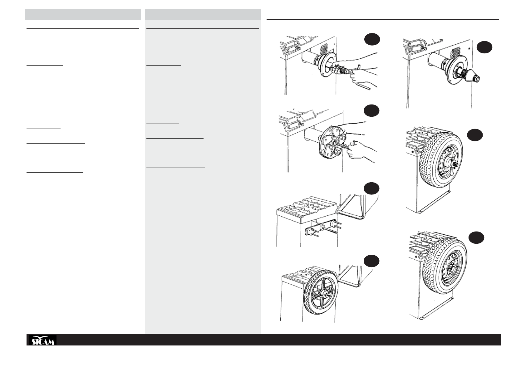
INST ALLAZIONE FLANGIA
9a
10c
10a
9b
10b
9c
11
Prima di fissare la flangia alla macchina è opportuno pulire sempre il cono
dell’albero macchina ed il foro della flangia stessa. Un cattivo adattamento
della flangia sull’albero influirà sulla precisione dell’equilibratura.
FITTING ADAPTERS
Before fitting adapters to the machine it is advisable to clean the machine
shaft cone and the hole in the adapter itself.
A badly fitted adapter will compromise the accuracy of balancing.
SBM 155
MONTAGGIO FLANGE
Prima di fissare le flange alla macchina è opportuno pulire il cono
dell’alberomacchina ed il foro della flangia stessa.
Un cattivo adattamento della flangia influirà sulla precisione
dell’equilibratura.
Le illustrazioni mostrano il sistema dei fissaggio delle flange:
» La fig.9a mostra il sistema di fissaggio della flangia a coni.
» La fig.9b mostra il sistema di fissaggio della flangia universale.
» La fig.9c mostra il sistema di fissaggio della flangia motociclo.
SERRAGGIO RUOTE
SERRAGGIO RUOTA AUTOMOBILE
» Le figure 10a e 10b mostrano il sistema di serraggio ruota d’automobile
utilizzando la flangia a coni.
» Le fig.10c mostra il sistema di serraggio ruota d’automobile utilizzando
la flangia univer-sale 3/4/5 fori.
SERRAGGIO RUOTA MOTOCICLO
» La fig.11 mostra il sistema di serraggio ruota motociclo utilizzando la
flangia moto.
FITTING ADAPTERS
Before fitting adapters to the machine it is advisable to clean the machine
shaft cone and the hole in the adapter itself.
A badly fitted adapter will compromise the accuracy of balancing.
The diagrams show the adapter locking system:
» Fig. 9a shows the locking system for the cone adapter.
» Fig. 9b shows the locking system for the universal adapter.
» Fig. 9c shows the locking system for the motorcycle adapter.
LOCKING WHEELS
LOCKING AUTOMOBILE WHEELS
» Figures 10a and 10b show the system for locking automobile wheels
using the cone adapter.
» Fig.10c shows the system for locking automobile wheels using the
universal 3/4/5 hole adapter.
LOCKING MOTORCYCLE WHEELS
» Fig.11 shows the system for locking motorcycle wheels using the
motorcycle adapter.
COD. 655632 Rev.0
12
Page 13
FRANÇAIS
DEUTSCH
ESPAÑOL
РУССКИЙ
INSTALLATION DU PLATEAU
Avant de fixer le plateau à la machine, bien nettoyer le cône de l’arbre de
la machine et le trou du plateau. Une mauvaise adaptation du plateau sur
l’arbre se répercutera sur la précision de l’équilibrage.
INSTALLA TION DER FLANSCHE
Vor der Befestigung eines Flansches an der Maschine sind der Kegel der
Maschinenwelle und die Öffnung des Flanschs selbst zu reinigen. Die
nicht korrekte Montage des Flanschs auf der Welle beeinträchtigt die
Auswuchtgenauigkeit.
INSTALACIÓN DE LA BRIDA
Antes de fijar la BRIDA a la máquina es oportuno limpiar el cono del árbol
de la máquina y el agujero de la BRIDA. Una mala adaptación de la BRIDA
al árbol influirá en la precisión del equilibrado.
УСТАНОВКА ФЛАНЦА
Перед установкой фланца на станке необходимо всегда очистить
конус вала станка и отверстие самого фланца. Плохая установка
фланца на валу будет влиять на точность балансировки.
MONTAGE DU PLATEAU
Avant de fixer les plateaux à la machine, bien nettoyer le cône de l’arbre
de la machine et le trou du plateau. Une mauvaise adaptation du plateau
sur l’arbre se répercutera sur la précision de l’équilibrage.
Les illustrations montrent le système de fixation des plateaux:
» La fig.9a montre le système de fixation du plateau à cônes.
» La fig.9b montre le système de fixation du plateau universel.
» La fig.9c montre le système de fixation du plateau de motocyclette.
SERRAGE DES ROUES
SERRAGE DE LA ROUE D’AUTOMOBILE
» Les figures 10a et 10b montrent le système de serrage de la roue de
tourisme en utilisant le plateau à cônes.
» La fig.10c montre le système de serrage de la roue d’automobile en
utilisant le plateau universel 3/4/5 trous.
SERRAGE DE LA ROUE DE MOTOCYCLETTE
» La fig.11 montre le système de serrage de la roue de motocyclette en
utilisant le plateau de moto.
MONTAGE DES FLANSCHS
Die Abbildungen veranschaulichen das Vorgehen zum Montieren der
Flansche:
» Abb.9a zeigt das Befestigungssystem des Kegelflanschs.
» Abb.9b zeigt das Befestigungssystem des universellen Flanschs.
» Abb.9c zeigt das Befestigungssystem des Motorradflanschs.
RÄDERBEFESTIGUNG
BEFESTIGUNG VON KFZ-RÄDERN
» Die Abbildungen 10a und 10b zeigen das Befestigungssystem des
Kraftfahrzeugrads unter Verwendung des Kegelflanschs.
» Abb.10c zeigt das Befestigungssystem des Kraftfahrzeugrads unter
Verwendung des universellen Flanschs mit 3/4/5 Bohrungen.
BEFESTIGUNG VON MOTORRADRÄDERN
» Abb.11 zeigt das Befestigungssystem für Motorradräder mit Hilfe eines
Motorradflanschs.
MONTAJE DE LAS BRIDAS
Antes de fijar las bridas a la máquina es oportuno limpiar el cono del árbol
de la máquina y el agujero de la BRIDA.
Una mala adaptación de la BRIDA influirá en la precisión del equilibrado.
Las ilustraciones muestran el sistema de fijación de las BRIDAS:
» La fig.9a muestra el sistema de fijación de la BRIDA de conos.
» La fig.9b muestra el sistema de fijación de la BRIDA universal.
» La fig.9c muestra el sistema de fijación de la BRIDA para
motocicleta.
SUJECIÓN DE LAS RUEDAS
SUJECIÓN RUEDA AUTOMÓVIL
» Las figuras 10a y 10b muestran el sistema de sujeción para rueda de
automóvil utilizando la BRIDA de conos.
» La fig.10c muestra el sistema de sujeción para rueda de automóvil
utilizando la BRIDA universal de 3/4/5 agujeros.
SUJECIÓN RUEDA MOTOCICLETA
» La fig.11 muestra el sistema de sujeción para rueda de motocicleta
utilizando la BRIDA para moto.
МОНТАЖ ФЛАНЦЕВ
Перед установкой фланца на станке необходимо очистить конус
вала
станка и отверстие самого фланца.
Плохая установка фланца будет влиять на точность
балансировки.
Иллюстрации показывают систему крепления фланцев:
» на рис.9a показана система крепления конусных фланцев.
» на рис.9b показана система крепления универсального
фланца.
» на рис.9c показана система крепления фланца для колес
мотоцикла.
БЛОКИРОВКА КОЛЕС
БЛОКИРОВКА АВТОМОБИЛЬНОГО КОЛЕСА
» На рисунках 10a и 10b показана система блокировки
автомобильного колеса, которая использует конусный
фланец.
» На рис.10c показана система блокировки автомобильного
колеса, которая использует универсальный фланец с 3/4/5
отверстиями.
БЛОКИРОВКА КОЛЕСА МОТОЦИКЛА
» На рис.11 показана система блокировки колеса мотоцикла,
которая использует специальный фланец для колес
мотоцикла.
COD. 655632 Rev.0
13
Page 14
ITALIANO
ENGLISH
12a
13
12b
14a
14b
SBM 155
15
INSTALLAZIONE FLANGIA PNEUMA TICA
Prima di fissare la flangia alla macchina è opportuno pulire sempre il cono
dell’albero macchina ed il foro della flangia stessa. Un cattivo adattamento
della flangia sull’albero influirà sulla precisione dell’equilibratura.
MONTAGGIO FLANGIA A CONI
» Accendere la macchina;
» Fare uscire il perno azionando il pedale verso l’alto;
» Avvitare completamente il tirante interno alla flangia sul perno filettato
dell’albero senza serrare con forza (fig.12a);
» Fare avanzare la flangia facendo entrare le viti nelle asole dell’anello di
aggancio (fig.12a);
» Ruotare l’anello fino a far entrare completamente le viti nelle asole
(fig.12b);
» Bloccare la flangia sull’albero azionando il pedale verso l’alto;
» Serrare le due viti con chiave di 13.
SMONTAGGIO FLANGIA A CONI
» Accendere la macchina;
» Sbloccare l’aggancio pneumatico azionando il pedale verso l’alto;
» Allentare le due viti che bloccano la flangia con chiave di 13;
» Sbloccare la flangia dall’albero con un colpo di martello in gomma sulla
campana;
» Ruotare la flangia fino a far corrispondere i fori dell’anello di aggancio
con la testa delle viti, quindi sfilarla;
» Svitare la flangia dal perno dell’albero.
MONTAGGIO FLANGIA MOTO E 3/4/5 FORI
» Accendere la macchina;
» Fare uscire il perno azionando il pedale verso l’alto;
» Posizionare la flangia sull’albero della macchina;
» Avvitare la ghiera di bloccaggio sul perno;
» Bloccare la flangia azionando il pedale verso l’alto.
SMONTAGGIO FLANGIA MOTO E 3/4/5 FORI
» Accendere la macchina;
» Fare uscire il perno azionando il pedale verso l’alto;
» Svitare la ghiera di bloccaggio sul perno;
» Sbloccare la flangia dall’albero con un colpo di martello in gomma
sulla campana;
SERRAGGIO RUOTA AUTOMOBILE
» Sbloccare l’aggancio pneumatico azionando il pedale verso l’alto;
» Posizionare opportunamente ruota e cono sull’albero;
» Infilare il manicotto di bloccaggio sull’albero spingendolo contro la
ruota(fig14a);
» Bloccare azionando il pedale verso l’alto.
» La fig.14b mostra il sistema di serraggio ruota d’automobile utilizzando
la flangia universale 3/4/5 fori.
SERRAGGIO RUOTA MOTOCICLO
» La fig.15 mostrano il sistema di serraggio ruota motociclo utilizzando
la flangia moto.
FITTING THE PNEUMATIC ADAPTER
Before fixing the adapter on the machine, the machine shaft cone and the
adapter hole should be cleaned. A poor adapter-shaft fastening will negatively influence balancing precision.
FITTING CONE ADAPTERS
» Switch on the machine.
» Bring out the shaft by pushing the pedal up.
» Completely screw the screw stay inside the adapter onto the threaded
section of the shaft without applying force (fig.12a).
» Advance the adapter, inserting the screws into the slots in the cou-
pling ring (fig.12a).
» Rotate the ring until the screws are completely inside the slots (fig.12b)
» Lock the adapter on the shaft by moving the pedal up.
» Tighten the two screws with a size 13 spanner.
REMOVING CONE ADAPTERS
» Switch on the machine.
» Release the pneumatic lock by moving the pedal up.
» Release the two screws that fix the adapter with a size 13 spanner.
» Release the adapter from the shaft by hitting the bell section with a
rubber mallet.
» Rotate the adapter until the coupling ring holes align to the screw
heads and then slide off.
» Unscrew the adapter from the shaft.
FITTING THE E 3/4/5 HOLE MOTORCYCLE ADAPTER
» Switch on the machine.
» Bring out the shaft by pushing the pedal up.
» Position the adapter on the machine shaft.
» Screw up the locking ring nut onto the shaft.
» Lock the adapter by moving the pedal up.
REMOVING THE E 3/4/5 HOLE MOTORCYCLE ADAPTER
» Switch on the machine.
» Bring out the shaft by pushing the pedal up.
» Unscrew the locking ring nut from the shaft.
» Release the adapter from the shaft by hitting the bell section with a
rubber mallet.
FIXING AUTOMOBILE WHEELS
» Release the pneumatic lock by moving the pedal up.
» Position the wheel and cone appropriately on the shaft.
» Slide on the locking collar onto the shaft pushing against the wheel
(fig14a).
» Lock by moving the pedal up.
» Fig.14b shows the automobile wheel fixing system using the univer-
sal 3/4/5 hole adapter.
FIXING MOTORCYCLE WHEELS
» Fig.15 shows the motorcycle wheel fixing system using the motor-
cycle adapter.
COD. 655632 Rev.0
14
Page 15
FRANÇAIS
DEUTSCH
ESPAÑOL
РУССКИЙ
INSTALLATION DU PLATEAU
Avant de fixer le plateau à la machine il faut toujours nettoyer le cône de
l’arbre et le trou du plateau. Une mauvaise adaptation du plateau sur l’arbre
se répercutera sur la précision du calibrage.
MONTAGE DU PLATEAU A CONES
» Allumer la machine;
» Sortir le pivot en actionnant la pédale vers le haut;
» Visser à fond le tirant à l’intérieur du plateau sur le pivot taraudé de
l’arbre sans trop serrer (fig.12a);
» Faire avancer le plateau en passant les vis dans les fentes de la bague
d’accrochage (fig.12a);
» Faire tourner la bague jusqu’à faire entrer les vis dans les fentes
complètement (fig.12b);
» Verrouiller le plateau sur l’arbre en actionnant la pédale vers le haut;
» Serrer les deux vis au moyen d’une clef de 13.
DEMONTAGE DU PLATEAU A CONES
» Allumer la machine;
» Déverrouiller l’accrochage pneumatique en actionnant la pédale vers le
haut;
» Desserrer les deux vis qui verrouillent le plateau avec une clef de 13;
» Déverrouiller le plateau de l’arbre par un coup de marteau en caoutch-
ouc sur la cloche;
» Faire tourner le plateau jusqu’à ce que les trous de la bague d’accrochage
correspondent à la tête des vis, ensuite le sortir;
» Dévisser le plateau du pivot de l’arbre.
MONTAGE DU PLATEAU A MOTO ET 3/4/5 TROUS
» Allumer la machine;
» Faire sortir le pivot en actionnant la pédale vers le haut;
» Placer le plateau sur l’arbre de la machine;
» Visser le collier de blocage sur le pivot;
» Verrouiller le plateau en actionnant la pédale vers le haut.
DEMONTAGE DU PLATEAU DE MOTO ET 3/4/5 TROUS
» Allumer la machine;
» Faire sortir le pivot en actionnant la pédale vers le haut;
» Dévisser l’embout de blocage sur le pivot;
» Débloquer le plateau de l’arbre avec un coup de marteau en caoutch-
ouc sur la cloche.
SERRAGE DE LA ROUE DE TOURISME
» Déverrouiller l’accrochage pneumatique en actionnant la pédale vers le
haut;
» Placer correctement la roue et le cône sur l’arbre;
» Enfiler le manchon de verrouillage sur l’arbre en le poussant contre la
roue (fig14a);
» Verrouiller en actionnant la pédale vers le haut.
» La fig.14b montre le système de serrage des roues de tourisme en
utilisant le plateau universel de 3/4/5 trous.
SERRAGE DE LA ROUE DE MOTO
» La fig. 15 montre le système de serrage de la roue de moto en utilisant
le plateau à moto
INSTALLA TION DES PNEUMATIKFLANSCHS
Vor der Befestigung eines Flansches an der Maschine sind der Kegel der
Maschinenwelle und die Öffnung des Flanschs selbst zu reinigen. Die
nicht korrekte Montage des Flanschs auf der Welle beeinträchtigt die
Auswuchtgenauigkeit.
MONTAGE DES KEGELFLANSCHS
» Die Maschine einschalten;
» Den Führungsstift durch Hochdrücken des Pedals heraustreten lassen;
» Den Zuganker im Flanschinneren vollständig auf den Gewindestift
schrauben ohne zu forcieren (Abb.12a);
» Den Flansch vorschieben bis die Schrauben in die Ösen des
Arretierrings vordringen (Abb.12a);
» Den Ring drehen bis die Schrauben komplett in die Ösen eingeführt
sind (Abb. 12b);
» Den Flansch durch Hochdrücken des Pedals auf der Welle blockieren;
» Die zwei Schrauben mit einem 13er Schlüssel festziehen.
DEMONTAGE DES KEGELFLANSCHS
» Die Maschine einschalten;
» Den Pneumatikanschluss Hochdrücken des Pedals auf der Welle lösen;
» Die zwei Schrauben, die den Flansch blockieren, mit einem 13er
Schlüssel lösen;
» Den Flansch mit einem Gummihammerschlag auf die Kopfseite lösen;
» Den Flansch drehen, bis die Bohrungen des Arretierrings zu den
Schraubenköpfen ausgerichtet sind, und dann herausziehen;
» Den Flansch vom Stift der Welle abschrauben.
MONTAGE DES MOTORRADFLANSCHS MIT 3/4/5 BOHRUNGEN
» Die Maschine einschalten;
» Den Führungsstift durch Hochdrücken des Pedals heraustreten lassen;
» Den Flansch auf der Welle der Maschine positionieren;
» Den Befestigungsstellring auf dem Stift befestigen;
» Den Flansch durch Hochdrücken des Pedals blockieren.
DEMONTAGE DES MOTORRADFLANSCHS MIT 3/4/5 BOHRUNGEN
» Die Maschine einschalten;
» Den Führungsstift durch Hochdrücken des Pedals heraustreten lassen;
» Den Befestigungsstellring vom Stift abschrauben;
» Den Flansch mit einem Gummihammerschlag auf die Kopfseite lösen;
BEFESTIGUNG EINES KFZ-RADS
» Den Pneumatikanschluss Hochdrücken des Pedals auf der Welle lösen;
» Rad und Kegel korrekt auf der Welle positionieren;
» Den Befestigungsstutzen auf die Welle schieben und bis zum Rad
drücken (Abb. 14a);
» Durch Hochdrücken des Pedals blockieren.
» Abb.14b zeigt das Kraftfahrzeugrad-Befestigungssystem unter
Verwendung des universellen Flanschs mit 3/4/5 Bohrungen.
BEFESTIGUNG EINES MOTORRAD—RADS
» Abb. 15 zeigt das Befestigungssystem für Motorradräder unter
Verwendung des Motorradflanschs.
INSTALACIÓN DE LA BRIDA NEUMÁTICA
Antes de fijar la BRIDA a la máquina es oportuno limpiar el cono del árbol
de la máquina y el agujero de la BRIDA. Una mala adaptación de la BRIDA
al árbol influirá en la precisión del equilibrado.
MONTAJE DE LA BRIDA DE CONOS
» Encender la máquina;
» Hacer salir el perno accionando el pedal hacia arriba;
» Enroscar completamente el tirante interno de la BRIDA en el perno
roscado del árbol, sin apretar con fuerza (fig.12a);
» Hacer avanzar la BRIDA, de modo que los tornillos entren en las ranuras
del anillo en conexión (fig.12a);
» Girar el anillo hasta que los tornillos hayan entrado por completo en
las ranuras (fig.12b);
» Bloquear la BRIDA en el árbol accionando el pedal hacia arriba;
» Apretar los dos tornillos con una llave del 13.
DESMONTAJE DE LA BRIDA DE CONOS
» Encender la máquina;
» Desbloquear la conexión neumática accionando el pedal hacia arriba;
» Aflojar los dos tornillos que fijan la BRIDA con una llave del 13;
» Liberar la BRIDA del árbol dando un golpe con un martillo de goma
sobre la campana;
» Girar la BRIDA hasta que los agujeros del anillo de conexión se
correspondan con las cabezas de los tornillos, sacarla entonces;
» Destornillar la BRIDA del perno del árbol.
MONTAJE DE LA BRIDA P ARA MOTO Y LA BRIDA DE 3/4/5 AGUJEROS
» Encender la máquina;
» Hacer salir el perno accionando el pedal hacia arriba;
» Colocar la BRIDA en el eje de la máquina;
» Enroscar la virola de bloqueo en el perno;
» Bloquear la BRIDA accionando el pedal hacia arriba;
DESMONTAJE DE LA BRIDA PARA MOTO Y DE 3/4/5 AGUJEROS
» Encender la máquina;
» Hacer salir el perno accionando el pedal hacia arriba;
» Desenroscar la virola de bloqueo en el perno;
» Liberar la BRIDA del árbol dando un golpe con un martillo de goma
sobre la campana;
SUJECIÓN DE RUEDA DE AUTOMÓVIL
» Desbloquear la conexión neumática accionando el pedal hacia arriba;
» Colocar convenientemente la rueda y el cono en el árbol;
» Introducir el acoplador de bloqueo en el árbol empujándolo contra la
rueda (fig14a);
» Bloquear accionando el pedal hacia arriba;
» La fig.14b muestra el sistema de sujeción para rueda de automóvil
utilizando la BRIDA universal de 3/4/5 agujeros.
SUJECIÓN RUEDA DE MOTOCICLETA
» La fig.15 muestra el sistema de sujeción para rueda de motocicleta
utilizando la BRIDA para moto.
УСТАНОВКА ПНЕВМАТИЧЕСКОГО ФЛАНЦА
Перед установкой фланца на станке необходимо очистить конус
вала станка и отверстие самого фланца.
Плохая установка фланца будет влиять на точность балансировки.
МОНТАЖ КОНУСНОГО ФЛАНЦА
» Включить станок;
» Перемещением педали вверх вывести наружу конец вала;
» Полностью завинтить фланец на резьбовом конце вала, не затягивая
его при этом с силой (рис.9);
» Подвигать вперед фланец таким образом, чтобы винты вошли в петли
крепежного кольца (рис.9);
» Поворачивать кольцо до тех пор, пока винты не зайдут полностью в
петли (рис.10);
» Перемещением педали вверх блокировать фланец на вале;
» Затянуть два винта гаечным ключом 13
ДЕМОНТАЖ КОНУСНОГО ФЛАНЦА
» Включить станок;
» Перемещением педали вверх деблокировать пневматическое
сцепление;
» Отвинтить два винта блокировки фланца гаечным ключом 13;
» Ударом резинового молотка по конусу деблокировать фланец;
» Поворачивать фланец до тех пор пока отверстия крепежного кольца
не совпадут с головками винтов и затем снять его;
» Свинтить фланец с конца вала.
МОНТАЖ ФЛАНЦА ДЛЯ КОЛЕС МОТОЦИКЛА И С 3/4/5 ОТВЕРСТИЯМИ
» Включить станок;
» Перемещением педали вверх вывести палец;
» Установить фланец на вал станка;
» Завинтить затяжное блокировочное кольцо на конце вала;
» Перемещением педали вверх блокировать фланец.
ДЕМОНТАЖ КОНУСНОГО ФЛАНЦА
» Включить станок;
» Деблокировать пневматическое сцепление перемещением
педали вверх;
» Свинтить блокировочную гайку на шейке вала;
» Ударом резинового молотка по конусу деблокировать фланец
îò âàëà;
БЛОКИРОВКА АВТОМОБИЛЬНОГО КОЛЕСА
» Перемещением педали вверх деблокировать пневматическое
сцепление;
» Установить соответствующим образом колесо и конус на вале;
» Вставить муфту блокировки на вале прижимая ее к колесу (рис.12);
» Перемещением педали вверх произвести блокировку.
» На рис.13 показана система крепления колеса автомобиля, с
использованием универсального фланца с 3/4/5 отверстиями.
БЛОКИРОВКА КОЛЕСА МОТОЦИКЛА
» На рис.14 показана система блокировки колеса мотоцикла, с
использованием фланца для колес мотоцикла.
COD. 655632 Rev.0
15
Page 16

MALFUNZIONAMENTI, LORO CAUSE E POSSIBILI RIMEDI
ITALIANO
indicazione
display
I display non si
illuminano
Err 1 All’accensione compare il messaggio Err 1 1. La scheda ha perso i dati di tarat ura e configurazione impostati in fabbrica
Err 2 Durante il ciclo di misura compare il messaggio Err 2 1. Il carter di protezione è stato sollevato prima del termine della misura 1. Attendere il ter mine del lancio di misura prima di sollevare il carter di protez ione
Err 3 Durante il ciclo di misura compare il messaggio Err 3 1. Al momento dell’avviamento (pressione del tasto START o abbassamento del carter) la ruota
Err 4 Il motore non ruota (se pr emuto START) o dopo circa 20’ compare il messaggio
Err 5 Alla fine del secondo lancio di taratura con la ruota sul display compare Err 5 1. Il peso di calibrazione non è stato applicato alla ruota
Err 6 Premendo il pulsante START appare il messaggio Err 6
Err 7 Alla fine del secondo lancio di taratura con la ruota sul display compare Err 7
Err 8 Alla fine del secondo lancio di taratura con la ruota sul display compare Err 8 1. Il pick-up di sinistra non è stato collegato corr ettamente o è difett os o oppure il cavo è interrotto. 1. Controllare il collegamento (ed eventualmente sostituire) il pick-up di sinistr a.
Err 9 Alla fine del secondo lancio di taratura con la ruota sul display compare Err 9 1. Il pick-up di destra non è stato collegato corr ettamente o è difettoso oppure il cavo è interrotto. 1. Controllare il collegamento (ed eventualmente sostituire) il pick-up di destra.
Err 10 Durante il lancio sul display compare Err 10 1. Difetto dei rivelatori della posizione nell’optoelettronica.
Err 11 Durante il lancio sul display compare Err 11
Err 17 Alla fine del lancio sul display compare Err 17 1. Peso fuori campo di regolazione (il peso nec essario per equilibrare la ruota è superiore ai 500
Err 18 Sul display compare Err 18 1. Dati della ruota non impostati 1. Impostare i dati della ruota prima di eseguire il lancio di misura
Err 19 Alla fine del secondo lancio di taratur a sul display compare Er r 19 1. Il segnale all’ingresso del pick-up di destra è inferiore a quello del pick-up di sinist ra
Err 20 Durante il ciclo di misura sul display compare Err 20: la velocità della ruot a è sc esa
Err 21 Durante il ciclo di misura sul display compare Err 20: possibile guast o alla par te
Err 22 Durante il lancio sul display compare Err 22 1. Irregolarità nei segnali dell’optoelettronica 1. a) verificare che la scheda optoelet tronica sia protetta dalla luce ambiente ed eventulmente coprirla;
La scheda non si alimenta. 1. Mancanza dell’alimentazione esterna o mancanza di una fase
Err 4
sotto al minimo per la misura.
elettrica.
Malfunzionamenti cause possibili rimedi
2. Rottura dei fusibili ne ll’impianto elet trico
3. Rottura dei fusibili sul pannello comandi
2. Una o più fasi di taratura o configurazione non sono state eseguite.
stava girando all’indietro
2. Avvolgimenti del motore invert iti
1. Il motore non riesce a raggiungere i giri necessari per una buona equilibr a tura
2. Malfunzionamento della scheda elettronica
3. Malfunzionamento dell’impianto elettrico
2. I pick-up non sono stati collegati
1. Il carter di protezione non è stato abbassat o
2. Rottura del microinterruttor e del carter
1. La differenza di fase f ra i 2 pick-up è troppo gr ande
2. Il motore non ruota
1. Difetto del rivelatore del passaggio per lo zero nell’optoelet tronica
2. Il motore non ruota
grammi)
1. È stato premuto il pedale del freno durante la misura
2. La velocità di rotazione del motore è irregolare
1. La scheda elettronica ha rilevato una condizione di pericolo legata alla velocità della ruot a t roppo
elevata durante una fase di inattività della macchina (l’alber o r uota a velocità elevata senza lo
START dell’operatore): la p arte elettrica di poten za viene di sabili t ata.
1. Controllare che fase e neutro, siano collegate all’equilibr atrice
2. Sostituzione dei fu sibili nell’impianto elettr ic o (l’eventuale rirottura dei fusibili implica un malfunzionamento della parte
elettrica)
3. Sostituzione dei fu sibili s ul pannello co mandi (l’eventuale rirottura dei fusibili implica un malfunzionamento della part e
elettronica).
1. Rifare tutte le fasi di taratura e c onfigurazione dell’equilibrat rice
2. Eseguire le programmazioni o tarature mancanti.
1. Accertarsi che la ruota sia ferma al momento dell’avviamento e comunque evitare di farla ruotare all’indietro al
momento dello START
2. Verificare il corretto collegamento del motore
1. Controllare la tensione di rete (probabilmente è bassa
2. Sostituzione della scheda elettronica
3. Sostituzione della parte elet trica
1. Ripetere da capo la taratura e applicare il peso di calibrazione quando previsto dalla procedur a di taratura ( vedi anche
“Taratur a base della macchi na”)
2. Controllare il collegamento dei pick-up.
1. Abbassare il carter di pr otezione a ruota montata
2. Sostituzione del microinterruttore.
1. a) verificare che il peso per t aratura sia stato applicato corrett amente;
b) verificare inoltre il collocamento della macchina: probabilmente non è stabile e vibra troppo;
c) se il problema persiste anche dopo avere fissato corrett amente la macchina occorr e controllare il collegamento dei
rilevatori e della scheda elettronica ( ed eventualmente sostituirli);
d) sostituire i pick-up;
e) se dopo aver sostituito i pick up non si r isolve il problema, sostit uir e la sc heda
1. a) verificare il collegamento della scheda optoelettronica
b) verificare che la scheda optoelet tronica sia protet ta dalla luce ambiente ed eventulmente coprirla;
c) se il difetto per mane cont rollare ed eventualmente sostituire la scheda optoelettronica
2. Controllare la parte elettrica
1. a) verificare il collegamento della scheda optoelettronica
b) verificare che la scheda optoelet tronica sia protet ta dalla luce ambiente ed eventulmente coprirla;
c) se il difetto per mane cont rollare ed eventualmente sostituire la scheda optoelettronica
2. Controllare la parte elettrica
1. a) controllare che il fissaggio della ruota sulla flangia sia stato ef fettuato c orrettamente;
b) ricercare ( ugualmente) la posizione esterna, applicare un peso di 100 grammi ed effettuare un lancio.
1. Probabile inversione del collegamento dei due pick-up: controllar e (e scambiare eventualmente) il collegamento dei
due pick-up.
1. Evitare di premere il pedale del freno quando il motore è in moto
2. a) fare attenzione a non urtare la macchina durant e il ciclo di misura
b) controllare la t ensione di r ete (probabilmente è bassa)
1. Spegnere la macchina, abbassare il carter di protezione e riaccendere successivamente la macchina senza muovere
la ruota: se la condizione di err or e persiste occorre c ontrollare (ed eventualmente sostituir e) la parte elettrica o la
parte elettronica (pannello comandi o scheda encoder).
b) se il difetto per mane cont rollare ed eventualmente sostituire la scheda optoelet tronica;
c) controllare ed eventualmente sostituire la scheda elettronica del pannello comandi.
COD. 655632 Rev.0
16
Page 17

ENGLISH
TROUBLESHOOTING
display malfunctioning Causes Trouble-shooting
Displays do not
come on
Err 1 Err 1 appears on power-up 1. The card has lost the calibration data and fac tory configuration set ting.
Err 2 During the measuring cycle the Err 2 message appear s. 1. The guard has been raised bef ore completion of measurements. 1. Wait for end of measuring launch before r aising guard.
Err 3 During the measuring cycle the Err 3 message appear s. 1. On st art-up (using START key or lowering guar d) the wheel was r otating backwards
Err 4 The motor does not turn (wit h START pressed) or after about 20 sec. the Err 4
Err 5 At end of second calibrat ing run with the wheel Err 5 appears on t he display. 1. Calibration weight has not been applied on the wheel.
Err 6 Message Er r 6 appears when pressing the START k ey.
Err 7 At end of second calibrat ing run with the wheel Err 7 appears on t he display
Err 8 At end of second calibrat ing run with the w heel E rr 8 appears on the display 1. The left pick- up has not been correctly connected or is defective or the cable is disconnected. 1. Check lef t pick-up connection (and replace if necessary).
Err 9 At end of second calibrat ing run with the w heel E rr 9 appears on the display 1. The right pick- up has not been correctly connected or is defective or the cable is disconnected. 1. Check r ight pick-up connection (and r eplace if nec ess ary).
Err 10 During launch Err 10 appears on the display. 1. Posit ion sensors in optoelectronics defective.
Err 11 During launch Err 11 appears on the display.
Err 17 At end of launch Err 17 appear s on display 1. Weight out of regulation field (weight necess ary for balancing the wheel is above 500 grams) 1. a) Check that the wheel is cor rectly fixed on the flange;
Err 18 Err 18 appears on display 1. Wheel data not set . 1. Set the wheel data before st arting the measuring cycle.
Err 19 “Er r 19” is displayed after the second calibration cycle. 1. The signal reading at the right pick-up is lower than that at the lef t pick-up.
Err 20 During measuring cycle Err 20 appears on display: the wheel speed has gone
Err 21 During measuring cycle Err 21 appears on display: possible electrical fault. 1. The electronic car d has found a condition of danger connected to a too-high w heel speed during an inactive
Err 22 During the launch Err 22 appears on display 1. Some fault in the optoelectronic signals. 1. a) check the optoelectronic car d is protected from daylight and cover if necessar y;
The card is not powered up. 1. Ext ernal supply off or phase not wor k ing.
message appears.
below the minimum for measurability.
2. Fuse blown in t he electrical plant.
3. Control panel fuse blown.
2. One or more calibrat ion or setting phases have not been carr ied out.
2. Motor winding inverted.
1. The motor cannot r eac h the revolutions needed for effective balancing
2. electronic card malfunctioning
3. electrical plant malfunctioning
2. The pick-ups have not been connected
1. The guard has not been low ered.
2. Guard microswitch broken
1. Phase diff erence between the 2 pick-ups is too large.
2. The motor will not turn
1. Passage through zero sensor defec tive in optoelectronics
2. The motor will not turn
1. 1 Brak e pedal operated during the measurement
2. Motor rotation speed irregular.
machine phase (the shaft rotates at high speed wit hout the operator having pressed the START command); the
electric p ower is d eactivated.
1. Check t hat positive/negative and neutral are connect ed up to balancer.
2. Replace fus es in electrical plant (blown f us es indicat e fault in electric plant)
3. Replace fus es on c ontrol panel (blown fuses indicate fault in electronic part).
1. Repeat all calibr ation and balancer configuration st ages
2. Perform missing programming or setting operations.
1. Ascert ain that the wheel is still before st art-up and in any case avoid rotating wheel backwards on
START.
2. Check f or correct motor connection.
1. Check mains voltage (it is pr obably low)
2. Replace electronic card
3. Replace electrical part
1. Repeat c alibr ation from beginning and apply the calibration weight when instructed in the calibration
procedure (also see “Basic Machi ne Calibrat ion”)
2. Check pick-up connections.
1. Lower guard with wheel mounted.
2. Replace microswitch.
1. a) check that the calibration weight has been correctly applied;
b) also check machine location; it is probably not stable and is vibrat ing exces sively;
c) if the pr oblem persists after having stabilised t he machine correctly, check t he s ensor and
electronic card connect ions (and replace if necessary);
d) replace pick-ups;
e) if after replacing pick-ups the problem is not solved, replace the card.
1. a) check optoelectronic card connection.
b) check the optoelectronic card is protec ted from daylight and cover if necessary;
c) if the defec t persists check and if neces sar y replace t he optoelectronic card.
2. Check elect rical part.
1. a) check optoelectronic card connection.
b) check the optoelectronic card is protec ted from daylight and cover if necessary;
c) if the defec t persists check and if neces sar y replace t he optoelectronic card.
2. Check elect rical part.
b) find (in any case) the external position, apply a 100 gram weight and launch a run..
1. The connections to the two pick- ups might be inverted. Check (and exchange if necessary).
1. Avoid pressing the brake pedal when the motor is operating.
2. beware of knocking the machine during the measuring cycle. check mains voltage (probably low)
1. Switch off the machine, lower the guard and switch the machine back on w ithout moving the wheel; if
the error per s ists, check (and r eplace if nec essar y) t he electric or electr onic part (contr ol panel or
encoder card).
b) if the defect persists check and if nec ess ary replace t he optoelectronic card.
c) check and if necessary replace the control panel electronic car d.
COD. 655632 Rev.0
17
Page 18

FRANÇAIS
ANOMALIES, CAUSES ET REMEDES POSSIBLES
indication
afficheur
Les afficheurs ne
s’allument pas
Err 1 A l’allumage apparaît le message Err 1 1. La carte a per du les données d’étalonnage et de conf igur ation introduits en usine
Err 2 Pendant le cycle de mesure apparaît le message Er r 2 1. Le carter de protection a été levé avant la fin de la mesure 1. Attendre la fin du lancer de mesure avant de lever le carter de protection
Err 3 Pendant le cycle de mesure apparaît le message Er r 3 1. Au moment de la mise en marche (frappe de la touche START ou abaissement du carter) la
Err 4 le moteur ne tourne pas (si START pressé) ou après environ 20’ apparaît le message
Err 5 A la fin du deuxième lancer d’étalonnage avec la roue, l’ afficheur montre Err 5 1. La masse de calibrage n’a pas été app liquée à la roue
Err 6 En appuyant sur le poussoir START apparaît le message Err 6
Err 7 A la fin du deuxième lancer d’étalonnage avec la roue, l’ afficheur montre Err 7
Err 8 A la fin du deuxième lancer d’étalonnage avec la roue, l’ afficheur montre Err 8 1. Le pick-up de gauche n’a pas été branché correctement: soit il est défectueux, soit le câble
Err 9
Err 10 pendant le lancer l’afficheur montre Err 10 1. Défaut des r eleveurs de la posit ion de l’opto.électr onique.
Err 11 Pendant le lancer l’afficheur montre Er r 11
Err 17 A la fin du lancer l’aff icheur montre Err 17 1. Masse hors champ de réglage (la masse nécessaire à équilibrer la roue est supérieure à 500
Err 18 L’afficheur montre Err 18 1. Les données de la roue n’ont pas été introduit es 1. Int roduire les données de la roue avant d’exécut er le lancer de mesure
Err 19 A la fin du deuxième lancement de tarage, Err 19 apparaît sur l’afficheur 1. La signalisation à l’entrée du pick-up de droite est inférieure à celle du pick-up de gauche 1. Probable inversion du branc hement des deux pick-up: contrôler ( et éventuellement invertir) le branchement des deux
Err 20 Pendant le cycle de mesure l’afficheur mont r e Err 20: la vitesse de la roue es t
Err 21 Pendant le cycle de mesure l’afficheur mont r e Err 20: possible panne à la par tie
Err 22 Pendant le lancer l’afficheur montre Er r 22 1. I rrégularités dans la signalisation de l’opto-électronique 1. a) vérif ier que la carte opto-électronique soit protégée de la lumière ambiante et éventuellement la couvrir;
La carte ne s’alimente pas. 1. Manque de l’alimentation ext érieure ou manque d’une phase
Err 4
A la fin du deuxième lancer d’étalonnage avec la roue, l’afficheur montre Er r 9 1. Le pick-up de droite n’a pas été branché correc tement: soit il est défectueux, soit le câble est
descendue sous le minimum pour la mesure.
électrique.
anomalies causes remèdes possibles
2. Ruptur e des fusibles dans le système électrique
3. Ruptur e des fusibles sur le panneau de commandes
2. Une ou plusieurs phases d’étalonnage n’ont pas été exécutées.
roue tournait vers l’ar rière
2. Bobines du moteur inversées
1. Le moteur n’ar rive pas à atteindre les tours nécessaires pour un bon équilibr age
2. Anomalies de la carte électronique
3. Anomalie dans le système électrique
2. Les pick-up n’ont pas été branchés
1. Le carter de protection n’a pas été abaissé
2. Ruptur e du micro- interrupteur du c arter
1. La différenc e de phase entre les 2 pick-up est trop importante
est interrompu.
interrompu.
2. Le moteur ne tour ne pas
1. Défaut du releveur du passage pour le zéro dans l’opt o-électronique
2. Le moteur ne tour ne pas
grammes)
1. On a appuyé sur la pédale du frein pendant la mesure
2. La vitesse de rotat ion du moteur es t irrégulière.
1. La carte élect ronique a détecté une condition de danger liée à la vitesse t rop élevée de la
roue pendant une phase d’inactivité de la machine (l’axe de la r oue tourne à vitesse élevée
sans le START de l’opérateur) : la partie électrique de puissance est désact ivée.
1. Contrôler que la phase et le neutre s oient branchés à l’équilibreuse
2. Remplacement des fusibles dans le système électr ique ( l’éventuelle nouvelle rupture des fusibles indique une
anomalie dans la partie électrique)
3. Remplacement des fusibles sur le panneau de commandes (l’éventuelle nouvelle rupture des fusibles indique une
anomalie dans la partie électronique).
1. Ref aire toutes les phases d’étalonnage et de configur ation de l’équilibreuse
2. Exécuter les programmations ou les étalonnages manquants.
1. S’assur er que la roue soit arrêtée au moment de la mise en marche et éviter de la faire tourner vers l’arrière au
moment du START
2. Vérifier le branchement correct du moteur
1. Contrôler la tension du réseau (elle est probablement basse
2. Remplacement de la carte électronique
3. Remplacement de la partie élect rique
1. Répéter l’étalonnage du début et appliquer la masse de calibrage quand c’est prévu par la procédure d’étalonnage
(voir aussi “Etalonnage base de la machine”)
2. Contrôler le branchement des pick-up.
1. Abaisser le carter de protect ion avec la roue montée
2. Remplacement du micro-interrupteur.
1. a) vérifier que la masse d’ étalonnage ait été appliquée correct ement;
b) vérifier aussi l’emplacement de la machine: probablement elle n’est pas s table et elle vibre trop;
c) si le problème persiste même après avoir fixé correc tement la machine, contrôler le branchement des dét ec teurs et
de la carte électronique ( et éventuellement les remplacer);
d) remplacer les pick-up;
e) si après avoir remplacé les pick-up le problème reste, remplacer la carte.
1. Contrôler le branchement (et éventuellement r emplacer) le pick- up de gauche.
1. Contrôler le branchement (et éventuellement r emplacer) le pick- up de dr oite.
1. a) vérifier le branchement de la carte opto- électronique
b) vérifier que la carte opto-électronique soit protégée de la lumière ambiante et éventuellement la couvrir;
c) si le défaut reste, contrôler et éventuellement remplacer la carte opto-électronique
2. Contrôler la partie électrique
1. a) vérifier le branchement de la carte opto- électronique
b) vérifier que la carte opto-électronique soit protégée de la lumière ambiante et éventuellement la couvrir;
c) si le défaut reste, contrôler et éventuellement remplacer la carte opto-électronique
2. Contrôler la partie électrique
1. a) cont rôler que la fixation de la roue sur le plat eau ait été faite correctement; b) chercher
(tout de même) la position extér ieure, appliquer une masse de 100 grammes et effectuer un lancer.
pick-up.
1. Eviter d’appuyer sur la pédale du frein quand le moteur est en marche
2. a) faire attention à ne pas heur ter la machine pendant le cycle de mesure
b) contrôler la t ens ion du r éseau (elle est probablement basse)
1. Et eindr e la machine, abaisser le carter de pr otection et rallumer ensuite la machine sans bouger la roue: si la
condition d’erreur reste, contrôler (et éventuellement remplacer) la partie électrique ou la part ie électronique (panneau
de commandes ou carte encodeur).
b) si le défaut reste, contrôler et éventuellement remplacer la carte opto-électronique;
c) contrôler et éventuellement remplacer la carte électr onique du panneau de commandes.
COD. 655632 Rev.0
18
Page 19

DEUTSCH
BETRIEBSSTÖRUNGEN, IHRE URSACHEN UND MÖGLICHE ABHILFEN
Video-angabe Betriebs- störungen Ursachen Mögliche Abhilfen
Die Displays
leuchten nicht auf.
Err 1 Beim Einschalten erscheint die Nac hricht Err 1 1. Die Karte hat die in der Fabr ik vorgegebenen E ich- und Konfigurat ionsd aten verloren
Err 2 Während des Messzyklusses erscheint die Nachricht Err 2 1. Die Schutzabdeckung w urde angehoben, bevor die Messung beendet war 1. Das Ende des Messstarts abwarten, bevor man die Schutzabdeckung anhebt
Err 3 Während des Messzyklusses erscheint die Nachricht Err 3 1. Beim Start (Drücken der START-Taste oder Senken der Schutz abdec kung) drehte sich das Rad
Err 4 Der Motor dreht nicht (ist START gedrückt) oder nach zirka 20’
Err 5 Am Ende des zweiten Eichstarts mit dem Rad erscheint auf dem
Err 6 Drückt man die START-Taste erscheint die Nachricht Err 6
Err 7 Am Ende des zweiten Eichstarts mit dem Rad erscheint auf dem Display
Err 8 Am Ende des zweiten Eichstarts mit dem Rad zeigt das Display Err 8 1. Der linke Pick-Up wur de nicht korrekt angesc hlosse n, ist defekt oder das Kabel ist unt erbrochen 1. Den Anschluss des linken Pick -Ups kontr ollieren und dieses eventuell ersetzen.
Err 9 Am Ende des zweiten Eichstarts mit dem rad zeigt das D isplay Er r 9 1. Der rechte Pick-Up wurde nicht korr ek t angeschlossen oder ist def ekt, oder das Kabel ist
Err 10 Während des Starts ersc heint auf dem Display Err 10 1. Defek t der Positionsabnehmer in der Optoelektronik
Err 11 Während des Starts ersc heint auf dem Display Err 11
Err 17 Am Ende des Starts erscheint auf dem Display Err 17 1. Gewicht außerhalb des Einst ellber eichs (das zur Auswucht ung erf orderliche Gewicht bet rägt mehr als
Err 18 Auf dem Display erscheint Err 18 1. Raddaten nicht vorgegeben 1. Die Raddaten vor dem Ausführen des Messstar ts vorgeben
Err 19 Am Ende des zweiten Eichstarts erscheint auf dem Display Err 19 1. Das Signal am Eingang des rechten Pick-Ups liegt unter dem des linken Pick-Ups
Err 20 Während des Messzyklussees erscheint auf dem Display Er r 20: die
Err 21 Während des Messzyklussees erscheint auf dem Display Er r 20:
Err 22 Während des Starts ersc heint auf dem Display Err 22 1. Unregelmäßigkeit der Signale der Optoelektronik 1. a) Überprüfen ob die optoelekt ronische Karte licht ges chützt ist und eventuell abdecken;
Die Karte w ird nicht gespeist. 1. Fehlen der externen Speisung oder F ehlen einer Phase
erscheint die Nachricht Err 4
Display Err 5
Err 7
Radgeschwindigkeit sank unter den M indestmesswert
mögliche Störung am elektrischen Teil.
2. Beschädigung der Schmelzdrähte in der elektrischen Anlage
3. Beschädigung der Schmelzdrähte an der Steuertaf el
2. Eine oder mehrer e E ich- oder Konfigur ationsphasen wurden nicht vorgenommen.
nach hinten
2. Motorwicklungen vertauscht
1. Der M otor erreicht die not wendigen Umdrehungen für eine erfolgreiche Auswuchtung nicht erreichen
2. Bet riebsstörung der elektr onisc hen Karte
3. Bet riebsstörung der elektr isc hen Anlage
1. Das K alibr ier gewicht wurde nicht am Rad angebr ac ht
2. Die Pick-Ups wurden nicht angeschloss en
1. Die Schutzabdeckung w urde nicht gesenkt
2. Beschädigung des Mikr osc halters der Schutzabdeckung
1. Der Phasenunterschied zwischen den 2 Pick-Ups ist zu groß
unterbrochen.
2. Der M otor dreht nicht
1. Defek t des Durchgangsabnehmers für Null in der Optoelektr onik
2. Der M otor dreht nicht
500 Gramm)
1. Während des Messens w urde das Bremspedal gedrückt
2. Die Dr ehges chwindigkeit des Motors ist unregelmäßig
1. Die elektronische Karte hat eine G efahrensituation her ausges tellt, die in Verbindung mit der zu hohen
Radgeschwindigkeit während einer Maschinenstillstandsphase steht (die Welle dreht sich mit
gehobener Geschwindigkeit, ohne den START des Bedieners): dem elektrischen Leistungsteil
wird die Freigabe entnommen
1. Kontrollieren, dass Phase und Neutr al an die Auswuchtmaschine angeschlossen sind
2. Ers atz der Schmelzdrähte in der elektrischen Anlage (erneute Bes chädigung der Schmelzdrähte deutet auf B etriebsstörungen
des elektrischen Teils hin)
3. Ers atz der Schmelzdrähte an der Steuertafel (erneute Beschädigung der Schmelzdrähte deutet auf Betriebsstörungen des
elektrischen Teils hin.
1. Alle Eich- und K onfigurationsphasen der Auswuc htmaschine wiederholen
2. Die fehlenden Programmierungen oder Eichungen vornehmen.
1. Sich darüber vergew is sern, dass das Rad beim Star t stillsteht und vermeiden, dieses beim START nach hinten zu drehen
2. Den korrekten Anschluss des Motors überprüfen
1. Die Netzspannung kontrollier en (wahrscheinlich niedr ig)
2. Ers atz der elektronischen Karte
3. Ers atz des elektrischen Teils
1. Die Eichung von Beginn an w ieder holen und das Kalibriergewicht anbringen, wenn dies der Eichvorgang vorsieht ( siehe auch
“Grundeichung der Maschine”)
2. Den Anschluss der Pick-Ups überprüfen.
1. Die Schutzabdeck ung bei angebr ac htem Rad senken
2. Ers atz des Mikroschalter s .
1. a) Überprüfen, ob das Eichgewicht korr ekt angebracht wurde;
b) zudem den Anschluss der Maschine kontrollieren: w ahrscheinlich ist sie nicht stabil und vibriert zu sehr;
c) hält das Problem auch nach kor rekter Befestigung der Maschine an, ist der Anschluss der Abnehmer der elektronischen
Karte zu kontrollie ren (eventuell Ersatz e rforderlich);
d) Pick-Up ersetzen;
e) löst man das Problem nach Ersetzen des Pick-U ps nicht, die Karte er s etzen.
1. Den Anschluss des rechten Pick-Ups kontrollieren und dies es eventuell ersetzen.
1. a) Den Anschluss der optoelektronischen Karte überpr üfen
b) sich darüber vergewisser n, dass die optoelektronische Karte lichtgeschüt zt ist und eventuell abdecken;
c) hält der Defekt an, die optoelek tronische Karte kontrollieren und eventuell ers etzen
2. Den elekt rischen Teil kontrollieren
1. a) den Anschluss der optoelektronischen Karte überprüf en
b) sich darüber vergewisser n, dass die optoelektronische Karte lichtgeschüt zt ist und eventuell abdecken;
c) hält der Defekt an, die opt oelek tronische Karte kontrollieren und eventuell ersetzen
2. Den elekt rischen Teil kontrollieren
1. a) k o ntrollieren, dass das R a d k o rrekt am F la n s c h b efestigt wurde;
b) die äussere Position (trotzdem) suchen und nach dem Anbringen eines Gewichts von 100 Gramm einen Start vornehmen.
1. Möglicher Ver tausch ds Anschlusses der beiden Pick-Ups, den Anschluss der beiden Pick-Ups k ontrollieren (und eventuell
auswechseln)
1. Nicht auf das Bremspedal drücken, wenn der Motor in B etrieb ist
a) darauf achten, dass die Maschine während des Mes sens keinen Stößen ausgesetzt ist
b) die Netzspannung kontrollieren (w ahrscheinlich niedrig)
1. Die Maschine aussc halt en, die Schutzabdeckung senken und die Maschine wieder einschalten ohne das Rad zu bewegen:
bleibt der Fehlerzustand bestehen, muss eine Kont rolle (und eventuell ein Ersatz) des elektrischen oder elektr onischen Teils
(Steuertaf el oder Encoderkarte) vorgenommen werden.
b) bleibt der Defekt bestehen, die opt oelek tronische Karte kontrollieren und eventuell ers etzen
c) die optoelektr onis iche Karte der St euertafel kont rollieren und eventuell ersetzen.
COD. 655632 Rev.0
19
Page 20

ESPAÑOL
MAL FUNCIONAMIENTO, SUS CAUSAS Y POSIBLES SOLUCIONES
indicación
pantalla
Las pantallas no
se iluminan
Err 1 Durante el encendido aparece el mensaje E rr 1 1. La tar jeta ha perdido los datos de calibrado y configur ac ión pr ogramados en la fábrica
Err 2 Durante el ciclo de medición aparece el mensaje Err 2 1. El cárter de protección ha sido elevado antes de ter minar la medición 1. Esperar a que termine el lanzamiento de medición antes de elevar el cárter de protección
Err 3 Durante el ciclo de medición aparece el mensaje Err 3 1. Durante la puesta en marcha (presión de la tecla START o bajada del cárter) la r ueda es taba girando
Err 4 El motor no rota (si s e pulsa START) o después de apr oximadamente 20’
Err 5 Al final del segundo lanzamiento de calibrado con la rueda en la pantalla
Err 6 Pulsando el botón START aparece el mensaje Err 6
Err 7 Al final del segundo lanzamiento de calibrado con la rueda en la pantalla
Err 8 Al final del segundo lanzamiento de calibrado con la rueda en la pantalla
Err 9 Al final del segundo lanzamiento de calibrado con la rueda en la pantalla
Err 10 Durante el lanzamiento en la pantalla aparece Err 10 1. Defecto de los detector es de la posición en la opt oelectrónica.
Err 11 Durante el lanzamiento en la pantalla aparece Err 11
Err 17 Al final del lanzamiento en la pantalla aparece Err 17 1. Peso fuera del campo de regulación (el peso necesario para equilibrar la rueda es super ior a 500
Err 18 En la pantalla aparece E rr 18 1. Datos de la rueda no introducidos 1. Introducir los dat os de la r ueda antes de realizar el lanzamiento de medición
Err 19 Al final del segundo lanzamiento de calibrado sobre el display aparece
Err 20 Durante el ciclo de medición en la pantalla aparece Err 20: la velocidad de
Err 21 Durante el ciclo de medición en la pantalla aparece Err 20: posible avería
Err 22 Durante el lanzamiento en la pantalla aparece Err 22 1. Irr egularidad en las señales de la optoelectrónica 1. a) verificar que la tarjeta optoelectr ónica esté protegida de la luz ambiente y eventualmente cubrirla;
La tarjet a no se alimenta. 1. F alt a de la alimentación externa o falta de una fase
aparece el mensaje Err 4
aparece Err 5
aparece Err 7
aparece Err 8
aparece Err 9
Err19
la rueda a bajado por debajo del mínimo para la medición.
en la parte eléctrica.
Mal funcionamiento causas posibles remedios
2. Rotura de los fusibles en la instalación eléctrica
3. Rotura de los fusibles en el panel de mandos
2. Una o más fases de calibrado o configuración no se han realizado.
hacia atrás
2. Arrollamientos del motor invertidos
1. El motor no consigue alcanz ar las revoluciones necesarias para un buen equilibrado
2. Mal funcionamiento de la tar jeta electrónica
3. Mal funcionamiento de la instalación eléctrica
1. El peso de calibración no ha sido aplicado a la rueda
2. Los pick-up no han sido conect ados
1. El cárter de protección no ha sido baj ado
2. Rotura del microinterruptor del cárter
1. La diferencia de fas e entre los 2 pick-up es demasiado grande
1. El pick-up de la izquierda no ha sido conectado correctamente o es defectuoso o el cable está
interrumpido.
1. El pick-up de la derec ha no ha sido conectado correctamente o es defectuoso o el cable está
interrumpido.
2. El motor no rota
1. Defec to del detector del pasaje por el cero en la optoelectr ónica
2. El motor no rota
gramos)
1. La señal al ingreso del pick-up de la derecha es inferior que el pick-up de la izquierda
1. Se ha presionado el pedal del freno durante la medición
2. La velocidad de rotación del motor es irregular
1. La tarjeta electrónica ha det ectado una condición de peligro legada a la velocidad de la rueda demasiado
elevada durante una fase de inactividad de la máquina (el árbol rota a velocidad elevada sin el START
del operador): la parte eléctrica de potencia viene deshabilitada.
1. Cont rolar que la fase y el neutro, es tén conectados a la equilibradora
2. Sustitución de los fusibles en la instalación eléctrica (si los fus ibles vuelven a romperse esto implica un mal
funcionamiento de la parte eléctr ica)
3. Sustitución de los fusibles en el panel de mandos (si los fusibles vuelven a romperse esto implica un mal
funcionamiento de la parte electr ónica).
1. Volver a hacer todas las fases de calibrado y configuración de la equilibradora
2. Realizar las pr ogramaciones o calibrados que falten.
1. Asegurarse de que la r ueda es té quieta al momento de la puesta en marcha y en todo caso evitar hacerla rotar hacia
atrás al momento del START
2. Verificar la correcta conexión del motor
1. Controlar la tensión de red (probablemente es baja
2. Sustitución de la tarjeta elect rónica)
3. Sustitución de la par te eléctrica
1. Repetir desde el principio el calibrado y aplicar el peso de calibración cuando lo prevé el procedimiento de calibrado
(ver también “Cali brado base de la máquina”)
2. Controlar la conexión de los pick-up.
1. Baj ar el cárter de pr otección con la rueda montada
2. Sustitución del microinterruptor.
1. a) verificar que el peso par a c alibr ado haya sido aplicado correctamente;
b) verificar además la colocación de la máquina probablemente no es estable y vibra demasiado;
c) si el problema persiste también después de haber fijado correctamente la máquina es necesario controlar la
conexión de los detectores y de la tarjeta electrónica (y eventualmente sustituirlos);
d) sustituir los pick-up;
e) si después de haber sustit uido los pick up no s e r es uelve el problema, sustit uir la tarjeta
1. Controlar la conexión (y eventualmente sustituir) el pick- up de la izquierda.
1. Controlar la conexión (y eventualmente sustituir) el pick- up de la derec ha.
1. a) verificar la conexión de la t arjeta optoelectrónica
b) verificar que la tarjeta optoelectrónica esté protegida de la luz ambiente y eventualmente cubrirla;
c) si el defecto pers iste controlar y eventualmente sustituir la tarjeta optoelectrónica
2. Controlar la parte eléctrica
1. a) verificar la conexión de la t arjeta optoelectrónica
b) verificar que la tarjeta optoelectrónica esté protegida de la luz ambiente y eventualmente cubrirla;
c) si el defecto pers iste controlar y eventualmente sustituir la tarjeta optoelectrónica
2. Controlar la parte eléctrica
1. a) cont rolar que la fijación de la rueda sobr e la brida haya sido efectuada correctamente;
b) buscar (igualmente) la posición ext erna, aplicar un peso de 100 gramos y efectuar un lanzamiento.
1. Probable inversión de la conexión de los dos pick- up: controlar (y cambiar eventualmente) la conexión de los dos
pick-up.
1. Evitar pisar el pedal del f reno cuando el motor está en movimiento
a) prestar atención a no golpear la máquina durante el ciclo de medición
b) controlar la t ens ión de r ed (probablemente es baja)
1. Apagar la máquina, bajar el cárter de prot ecc ión y volver a encender sucesivamente la máquina sin mover la rueda: si
la condición de error persist e es neces ario controlar (y eventualmente sustituir ) la parte eléctrica o la parte electrónica
(panel de mandos o tarjeta enc oder).
b) si el defecto persiste controlar y eventualmente sustituir la tarjeta optoelectrónica;
c) controlar y eventualmente sustit uir la tarjet a electrónica del panel de mandos.
COD. 655632 Rev.0
20
Page 21

РУССКИЙ
НЕИСПРАВНОСТИ, ИХ ПРИЧИНЫ И ВОЗМОЖНЫЕ СПОСОБЫ УСТРАНЕНИЯ
Показания
дисплея
Дисплей не
освеще н
Err 1 При включении появляется сообщение Err 1 1. Плата потеряла данные проведенной на заводе калибровки и конфигурации
Err 2 Во время измерительного цикла появляется сообщение Err 2 1 . Защитный кожух был поднят раньше окончания измерительного цикла. 1. Подождать окончание измерительного цикла и затем поднимать защитный кожух.
Err 3 Во время измерительного цикла появляется сообщение Err 3 1 . В момент запуска (нажатия кнопки START или опускания кожуха) колесо вращалось в против оположном
Err 4 Д вигатель не вращается (при нажатии кнопки START) или
Err 5 В конце второго запуска калибровки с колесом на дисплее
Err 6 При нажатии кнопки START появляется сообщение Err 6
Err 7 В конце второго запуска калибровки с колесом на дисплее
Err 8 В конце второго запуска калибровки с колесом на дисплее
Err 9
Err 10
Err 11
Err 17
Err 18 В конце запуска на дисплее появляется Err 18
Err 19 В конце второго запуска тарирования на дисплее
Err 20 Во время измерения на дисплее высвечивается Err 20:
Err 21
Err 22 Во время запуска на дисплее высвечивается Err 22 1. Ошибки в сигналах оптоэлектронного оборудования 1. a) удостовериться, что оптоэлектронная плата защищена от освещения среды и, при необходимости, покрыть
На плате нет питания. 1. Отсутствует питани е в сети или не хватае т одной фазы
после 20’ появляется сообщение Err 4
появляется Err 5
появляется Err 7
появляется Err 8
В конце второго запуска калибровки с колесом на дисплее
появляется Err 9
Во время запуска на дисплее высвечивается Err 10 1. Поломка датчиков позиции в оптоэлектронике.
Во время запуска на дисплее появляется Err 11
В конце запуска на дисплее появляется Err 17 1. Груз вне поля регулирования (необходимый для балансировки колеса груз превышает 500 грамм) 1. a) проверить правильность крепления колеса на фланце
появляется Err 19
скорость колеса уменьшилась и имеет значение ниже
минимального необходимого для проведения измерений
Во время измерения на дисплее высвечивается Err 21:
возможны поломки электрической части оборудования.
неиспр авности причины возможные способы устранения
1. Проверить подключение фаз и нейтрального провода к балансировочному станку
2. Поломка предохранителей электрического оборудования
3. Поломка предохранителей на пульте управления
2. Не были проведены одна или несколько стадий калибровки или конфигурации.
направлении
2. Поменяны местами обмотки двигателя
1. Двигатель не в состоянии набрать обороты, необходимые для выполнения хорошей балансировки
2. Плохая раб ота электронной платы
3. Плохая раб ота электрооборудования
1. Не установлен эталонный груз
2. Не подсоединены датчики pick-up
1. Не был опущен защитный кожух
2. Поломка микровыключателя кожуха
1. Слишком большая разница по фазе между 2-мя порогами срабатывания pick-up
1. Левый pick-up соединен неправильно или поломан, или прерван провод 1. Проверить соединение левого датчика pick-up (и в случае необходимости заменить)
1. Правый pick-up соединен неправильно или поломан, или прерван провод. 1. Проверить соединение правого датчика pick-up (и в случае необходимости заменить)
2. Двигатель не вращается
1. Полом ка датчиков прохода че рез ноль в оптоэле ктронике
2. Двигатель не вращается
1. Не заданы данные колеса
1. Сигнал на вход е правого датчика “pick-up″ ниже сигнала левого датчика “pick-up″
1. Во время измерения была нажата педаль тормоза
2. Скорость вращения двигателя нерегулярна
1. Электронная плата обнаружила опасную ситуацию связанную с высокой скоростью колеса в нерабочей
стадии станка (вал вращается с высокой скоростью без команды START оператора):
электрическая мощность
.
отключается
2. Заменить предохранители (повторная полом ка предохранителей указывает на плохую раб оту электрической
части об орудования)
3. Заменить предохранители (пов торная поломка предохраните лей указывает на плохую раб оту электронной
части об орудования)
1. Проделать сн ова все операции калибровки и конфигурац ии балансировоч ного станка
2. Проделать недостающее программирование или калибровку.
1. Удостовериться, ч то в момент запуска колесо не вращается и, в любом случае, стараться не вращать его в
противоположн ом направлении в момент ПУСКА
2. Проверить правильность электрического подсоединения двигателя
1. Проверить напряжени е сети (возмож но низкое )
2. Заменить электронную плату
3. Заменить электрооборуд ование
1. Повторить сначала операцию калибровки и завинтить эталонный груз придерживаясь процедуры калибровки
(см. также “Основная калиб ровка станка“)
2. Проверить подсоединение датчиков “pick-up“
1. Опустить защ итный кожух при установленн ом колесе
2. Заменить микровыключатель.
1. a) проверить правильность установки эталонного грузика;
b) проверить также ус тановку станка: не ис ключено, что он установлен плохо и сильно ви брирует;
c) если проблема остается и после корректного закрепления станка, необходимо проверить соединения
датчиков и электронной платы (и, при необходимости, заменить их)
d) заменить pick-up;
e) если после замены датчиков pick-up проблема остается, заменить плату
1. a) проверить соединения оптоэлектронной платы
b) удостов ериться, что оптоэ лектронная плата за щищена от освещ ения среды и, при необходи мости,
покрыть ее;
c) если поломка остается проверить и при необходимости заменить оптоэлектронную плату
2. Проверить электрическую часть оборудования
1. a) проверить соединения оптоэлектронной платы
b) удостов ериться, что оптоэ лектронная плата за щищена от освещ ения среды и, при необходи мости,
покрыть ее;
c) если поломка остается проверить и при необходимости заменить оптоэлектронную плату
2. Проверить электрическую часть оборудования
b) найти (в любом случае) внешнюю позицию, установить 100 граммовый грузик и произвести запуск
1. При помощи клавиатуры ввести данные колеса
1. Возможно, что поменяли местами соединения двух датчиков “pick-up″: проверить (и при
необходимости поменять) соединения двух датчиков “pick-up″.
1. Не н ажимать тормозную п едаль при действ ующем двигателе
а) быть вниматель ными и не толкать станок во время измерений
b) Проверить напряжение электросети (не исключено, что она является низкой)
1. Выключ ить станок, опустить з ащитный кожух и затем включить станок не вращая колесо: если продолжает
показывать наличие поломки необходимо проверить (и при надобности заменить) электрическую или
электронную часть оборудован ия (панель уп равления или плату код ирующего устройства)
ее;
b) если поломка останется проверить и при необходимости заменить оптоэлектронную плату;
c) проверить и при необходимости заменить электронную плату панели управления.
COD. 655632 Rev.0
21
Page 22

ITALIANO
ENGLISH
ISTRUZIONI PER L’USO
17
18
SBM 155
INSTRUCTIONS FOR USE
PANNELLO COMANDI - LEGENDA
1. Visualizzatore dati
2. Diodi luminosi di direzione punto di squilibrio
3. Punto di squilibrio (LED)
4. TastI impostazione distanza cerchio
5. TastI impostazione diametro cerchio
6. TastI impostazione larghezza cerchio
7. Tasto selezione unità di misura per larghezza o diametro cerchio (mm/inch)
8. Tasto selezione programma di equilibratura (MODE)
9. Tasto selezione utente
10. Tasti incremento / decremento dati
11. Tasto conferma dato
12.Tasto ottimizzazione
13.Tasto SPLIT
14. Tasto funzioni di controllo (MENÙ)
15. Indicatori selezione utente
16. Indicatore selezione programma pax
17. Indicatori selezione programma di equilibratura
18. Indicatori selezione programma di ottimizzazione
19. Indicatori selezione programma di separazione pesi
20. Indicatore selezione misura distanza
21. Indicatore selezione misura larghezza
22. Indicatore selezione misura diametro
23. Indicatore selezione unità di misura
24.Tasto START
25.Tasto STOP
» Quando la rotazione non è effettuata tramite il motore elettrico, premendo
il pedale verso il basso si blocca la rotazione della ruota.
» Per azionare il sistema pneumatico di bloccaggio / sbloccaggio flangia
tirare il pedale verso l’alto (fig.17).
» per acquisire le posizioni dei pesi da applicare con il calibro ALUDATA
tirare il pedale verso l’alto (fig.17).
CONTROL PANEL - KEY
1. Data display
2. Luminous diode imbalance direction indicators
3. Imbalance point (LED)
4. Rim distance setting buttons
5. Rim diameter setting buttons
6. Rim width setting buttons
7. Unit of measurement selection button for rim width or diameter (mm/inch)
8. Balancing program selection button (MODE)
9. Select user button
10. Data increase/decrease buttons
11. Data confirm button
12.Optimization button
13. SPLIT button
14. Control functions button (MENU)
15. User selection indicators
16. Pax program selection indicator
17. Balancing program selection indicators
18. Optimization program selection indicators
19. Weight separation program indicators
20. Distance measurement selection indicator
21. Width measurement selection indicator
22. Diameter measurement selection indicator
23. Unit of measurement selection indicator
24. START button
25. STOP button
» When the wheel is not being driven by the electrical motor, pressing
the brake pedal locks the rotation of the wheel.
» In order to activate the pneumatic adapter /locking/unlocking system
push the pedal up (fig.17).
» To read the positions for weight application with the ALUDATA gauge,
push the pedal up (fig.17).
COD. 655632 Rev.0
22
Page 23

FRANÇAIS
DEUTSCH
ESPAÑOL
РУССКИЙ
INSTRUCTIONS D’UTILISATION
BEDIENUNGSANLEITUNG
INSTRUCCIONES PARA EL USO
ИНСТРУКЦИИ ПО ЭКСПЛУАТАЦИИ
PANNEAU DE COMMANDES - LEGENDE
1. Afficheur de données
2. Diodes lumineuses de direction du point de balourd
3. Point de balourd (LED)
4. Touches d’introduction de la distance de la jante
5. Touches d’introduction du diamètre de la jante
6. Touches d’introduction de la largeur de la jante
7. Touche de sélection de l’unité de mesure pour la largeur ou le diamètre
de la jante (mm/pouces)
8. Touche de sélection du programme d’équilibrage (MODE)
9. Touche de sélection de l’utilisateur
10. Touche accroissement/décrément des données
11. Touche de validation de la donnée
12.Touche de l’optimisation
13.Touche SPLIT
14. Touche des fonctions de contrôle (MENU)
15. Indicateurs de sélection de l’utilisateur
16. Indicateur de sélection du programme pax
17. Indicateurs de sélection du programme d’équilibrage
18. Indicateurs de sélection du programme d’optimisation
19. Indicateurs de sélection du programme de séparation des poids
20. Indicateur de sélection de mesure de distance
21. Indicateur de sélection de mesure de largeur
22. Indicateur de sélection de mesure de diamètre
23. Indicateur de sélection de l’unité de mesure
24.Touche START
25.Touche STOP
» Quand la rotation n’est pas conduite à travers le moteur électrique, la
rotation de la roue se bloque en pressant sur la pédale vers le bas.
» Pour actionner le système pneumatique de blocage/déblocage du pla-
teau tirer la pédale vers le haut (fig.17).
» Pour acquérir les positions des masses à appliquer avec la pige
ALUDATA tirer la pédale vers le haut (fig.17).
STEUERTAFEL - LEGENDE
1. Datenanzeige
2. Leuchtpfeile zur Unwuchtanzeige
3. Unwuchtstelle (LED)
4. Tasten zur Einstellung des Felgenabstands
5. Tasten zur Einstellung des Felgendurchmessers
6. Tasten zur Einstellung der Felgenbreite
7. Auswahltaste für Maßeinheit der Anzeige von Felgenbreite und durchmesser (mm/inch)
8. Auswahltaste für das Auswuchtprogramm (MODE)
9. Bedienerauswahltaste
10. Tasten Parameter größer/ kleiner
11. Bestätigungstaste für Dateneingabe
12.Optimierungstaste
13.SPLIT-Taste
14.Funktionstasten (MENÜ)
15. Anzeiger Bedienerauswahl
16. Anzeiger Pax-Programmauswahl
17. Anzeiger Ausgleichsprogrammauswahl
18. Anzeiger Optimierungsprogrammauswahl
19. Anzeiger Auswahl Gewichtstrennungsprogramm
20. Anzeiger Distanzmassauswahl
21. Anzeiger Breitenmassauswahl
22. Anzeiger Durchmessermassauswal
23. Anzeiger für Maßeinheit der Anzeige.
24.START-Taste
25.STOP-Taste
» Erfolgt die Drehung nicht mittels Elektromotor, wird bei Drücken des
Bremspedals die Raddrehung blockiert.
» Zur Aktivierung des Pneumatiksystems zum Sperren/Freigeben des
Flanschs, das Pedal nach oben drücken (Abb. 17).
» Zur Erfassung der Positionen der mit dem Kaliber ALUDATA
anzubringenden Gegengewichte das Pedal nach oben drücken
(Abb.17).
PANEL DE MANDOS - LEYENDA
1. Visualizador de datos
2. Diodos luminosos de dirección punto de desequilibrio
3. Punto de desequilibrio (LED)
4. Teclas de introducción de la distancia de la llanta
5. Teclas de introducción del diámetro de la llanta
6. Teclas de introducción de la anchura de la llanta
7. Tecla de selección de la unidad de medida para la anchura o el diámetro
de la llanta (mm/inch)
8. Tecla de selección del programa de equilibrado (MODE)
9. Tecla de selección usuario
10. Teclas aumento / disminución datos
11. Tecla de confirmación del dato
12.Tecla de optimización
13.Tecla de SPLIT
14. Tecla funciones de control (MENÚ)
15. Indicadores de selección de usuario
16. Indicador de selección del programa pax
17. Indicadores de selección del programa de equilibrado
18. Indicadores de selección del programa de optimización
19. Indicadores de selección del programa de separación de pesos
20. Indicador de selección de la medida de distancia
21. Indicador de selección de la medida de anchura
22. Indicador de selección de la medida de diámetro
23. Indicador de selección de la unidad de medida.
24.Tecla de START
25.Tecla de STOP
» Cuando la rotación no se efectúa mediante el motor eléctrico, pisando
el pedal hacia abajo se bloquea la rotación de la rueda.
» Para accionar el sistema neumático de bloqueo/desbloqueo de la
BRIDA tirar del pedal hacia arriba (fig.17).
» Para adquirir las posiciones de los pesos a aplicar con el calibre
ALUDATA tirar del pedal hacia arriba (fig.17).
ПАНЕЛЬ УПРАВЛЕНИЯ - ОБОЗНАЧЕНИЯ
1. Показ данных
2. Светоизлучающие диоды направления точки дисбаланса
3. Точка дисбаланса (LED)
4. Кнопка ввода данных расстояния диска
5. Кнопка ввода данных диаметра диска
6. Кнопка ввода данных ширины диска
7. Кнопка выбора единицы измерения для ширины и диаметра
диска (мм/дюйм)
8. Кнопка выбора программы балансировки (MODE)
9. Кнопка выбора пользователя
10. Кнопки увиличение/уменшение значений данных
11. Кнопка подтверждения значения
12.Кнопка оптимизации
13.Кнопка SPLIT
14.Кнопка контроля функций (MENЩ)
15. Указатели выбора потребителя
16. Указатель выбора программы pax
17. Указатели выбора программы балансировки
18. Указатели выбора программы оптимизации
19. Указатели выбора программы разделения грузиков
20. Указатель выбора измерения расстояния
21. Указатель выбора измерения ширины
22. Указатель выбора измерения диаметра
23. Указатель выбора единицы измерения
24.Кнопка START
25.Кнопка STOP
» Когда вращение осуществляется не электрическим
двигателем, при нажатии педали вниз вращение колеса
останавливается.
» Для приведения в действие пневматической системы
блокировки/деблокировки фланца, переместить педаль вверх
(рис. 17).
» для определения места установки балансировочных грузиков
посредством мерной линейки ALUDATA, переместить педаль
вверх (рис.17).
COD. 655632 Rev.0
23
Page 24

ITALIANO
ENGLISH
FRANÇAIS
EQUILIBRATURA RUOTE
WHEEL BALANCING
EQUILIBRAGE DES ROUES
Accendere la macchina mediante l’interruttore principale.
» All’accensione la macchina visualizza l’indicazione della versione software per alcuni secondi;
al termine i visualizzatori (fig.18) (1) evidenziano 0 0.
» Montare la ruota sulla macchina centrandola sull’apposita flangia e serrandola accuratamente
» Per equilibrare la ruota occorre inserire i seguenti dati:
a) selezione del tipo di ruota e del programma di equilibratura che definisce il posizionamento
dei contrappesi sul cerchio (vedi paragrafo “Selezione programma di equilibratura”).
b) impostazione delle misure della ruota: larghezza nominale e diametro nominale (vedi
paragrafo “Impostazione dati ruota”).
c) impostazione della distanza tra la macchina ed il fianco interno del cerchio (vedi paragrafo
“Impostazione dati ruota”).
» Dopo aver chiuso il carter di protezione della ruota premere il tasto di avviamento, START (fig.18)
iniziando così il ciclo di misura.
» Durante la fase di misura si spengono le letture eccetto un segmento centrale nel visualizzatore.
» La grandezza e posizione degli squilibri dei due lati della ruota vengono determinati in un unico
lancio di misura, e sono indicati separatamente sui visualizzatori.
» Determinati i dati della misurazione, la ruota viene frenata automaticamente fino all’arresto.
» La protezione della ruota non deve essere aperta prima. Il tasto di arresto STOP (fig.18) ha la
funzione di bloccare la macchina in caso di emergenza.
» La grandezza e posizione degli squilibri dei due lati della ruota vengono determinati in un unico
lancio di misura, e sono indicati separatamente sui visualizzatori: a sinistra è indicato lo squilibrio
del fianco interno della ruota (rivolto verso la macchina) e a destra quello del fianco esterno.
» I diodi luminosi a forma di freccia (fig. 18) (2) indicano la direzione in cui deve essere girata la
ruota per il posizionamento nel corretto punto di equilibratura (indicazione separata per ciascun
lato della ruota).
» Si deve girare a mano la ruota finchè il LED (fig.18) (3) non si accende; il segnale acustico, se
abilitato, indica il raggiungimento della posizione corretta.
» Quindi si applica il peso di equilibratura richiesto nei lati rispettivi della ruota, in posizione
perpendicolare in alto (ore 12) sull’albero principale.
» Messi i contrappesi nelle posizioni corrette, riavviare la macchina (chiudere il carter di protezione
e premere START) per verificare l’esatta equilibratura ruota.
Switch on the machine with the main switch.
» When switched on the machine displays the software version for a few seconds. After this the
displays (fig.18) (1) read 0 0.
» Mount the wheel on the machine, centering it on the relevant adapter and tighten it carefully.
» To balance a wheel the following data must be entered:
a) Select wheel type and balancing program, which defines the positioning of the counter-
weights on the rim (see section “Selecting balancing program”).
b) Set the wheel measurements: nominal width and nominal diameter (see paragraph “Setting
wheel data”).
c) Set the distance between the machine and the internal side of the rim (see paragraph
“Setting wheel data”).
» After closing the wheel guard cover press the START (fig.18) button to start the balancing cycle.
» During the measuring stage the readings go blank apart from a central segment of the display.
» The scale and position of the imbalances on the two sides of the wheel are measured in a single
measuring cycle and they are displayed separately on the two displays.
» When the figures have been established the wheel is automatically braked to a stop.
» The wheel guard must not be opened before the wheel stops. The STOP (fig.18) button serves
to stop the machine immediately in emergencies.
» The scale and position of the imbalances on the two sides of the wheel are measured in a single
measuring cycle and they are displayed separately on the displays: on the left the imbalance on
the inside of the wheel (towards the machine), and on the right the outside of the wheel.
» The luminous diode arrows (fig. 18) (2) indicate the direction in which the wheel must be turned
to reach the correct point for balancing (separate indications for each side of the wheel).
» Turn the wheel manually until the LED’s (fig.18) (3) light up. If the sound signal is enabled it also
indicates when the correct position is reached.
» The required balancing weights are fitted on the respective sides of the wheel at the top (12
o’clock), perpendicular to the main shaft.
» With the counterweights correctly in position, restart the machine (close the guard cover and
press START) to check the correct balancing of the wheel.
Allumer la machine par l’interrupteur principal.
» A l’allumage la machine affiche pour quelques secondes l’indication de la version du logiciel;
à la fin, les afficheurs (fig.18) (1) montrent 0 0.
» Monter la roue sur la machine en la centrant sur le plateau prévu en la serrant bien
» Pour équilibrer la roue il faut introduire les données suivantes:
a) sélection du type de roue et du programme d’équilibrage qui définit le positionnement des
masses sur la jante (voir paragraphe “Sélection du programme d’équilibrage”).
b) introduction des mesures de la roue: largeur nominale et diamètre nominal (voir paragraphe
“Introduction des données de la roue”).
c) introduction de la distance entre la machine et le flanc intérieur de la jante (voir paragraphe
“Introduction des données de la roue”).
» Après avoir fermé le carter de protection de la roue taper sur la touche de mise en marche, START
(fig.18) en commençant le cycle de mesure.
» Pendant la mesure, les lectures s’éteignent à l’exception d’un segment au centre de l’afficheur.
» L’ampleur et la position des balourds des deux côtés de la roue sont déterminées en un seul
lancer de mesure, et sont indiquées séparément sur les afficheurs.
» Après avoir déterminé les données de la mesure, la roue est automatiquement freinée jusqu’à
son arrêt.
» La protection de la roue ne doit pas être ouverte avant. La touche d’arrêt STOP (fig.18) a la
fonction de bloquer la machine en cas d’urgence.
» L’ampleur et la position des balourds des deux côtés de la roue sont déterminées en un seul
lancer de mesure, et sont indiquées séparément sur les afficheurs: le balourd du côté interne de
la roue (tourné vers la voiture) est indiqué à gauche et celui du côté externe de la voiture, à droite.
» Les diodes lumineuses en forme de flèche (fig. 18) (2) indiquent la direction vers laquelle doit être
tournée la roue pour le positionnement au point d’équilibrage correct (indication séparée pour
chaque côté de la roue).
» Tourner la roue à la main jusqu’à ce que la LED (fig.18) (3) s’allume; la signalisation acoustique,
si établie, indique que la position correcte a été atteinte.
» Appliquer ensuite la masse d’équilibrage requise aux côtés respectifs de la roue, en position
perpendiculaire en haut (12 heures) sur l’arbre principal.
» Après avoir appliqué les masses aux endroits corrects, remettre en marche la machine (fermer
le carter de protection et presser START) pour vérifier l’équilibrage correct de la roue.
COD. 655632 Rev.0
24
Page 25

DEUTSCH
ESPAÑOL
РУССКИЙ
RADAUSWUCHTUNG
EQUILIBRADO DE LAS RUEDAS
БАЛАНСИРОВКА КОЛЕС
Die Maschine durch Betätigung des Hauptschalters einschalten.
» Beim Einschalten der Maschine wird auf dem Bildschirm für einige Sekunden die Softwareversion
angezeigt und anschließend ist auf den Anzeigen (Abb.18) (1) 0 0 zu lesen.
» Das Rad an der Maschine anbringen, indem man es auf dem vorgesehenen Flansch zentriert und
sorgfältig befestigt.
» Zur Radauswuchtung müssen folgende Daten eingegeben werden:
a) Wahl des Radtyps und des Auswuchtprogramms, das die Positionierung der
Gegengewichte auf der Felge bestimmt (siehe Abschnitt „Auswuchtprogrammwahl”).
b) Vorgabe der Raddaten: Nennbreite und Nenndurchmesser (s. Abschnitt „Vorgabe
Raddaten”).
c) Vorgabe der Entfernung zwischen der Maschine und der Innenseite der Felge (s. Abschnitt
„Vorgabe Raddaten”).
» Nach Schließen der Radschutzabdeckung die START-Taste (Abb.18) drücken und so den
Messzyklus beginnen
» Während der Messphase schalten sich außer dem mittleren Segment alle Anzeigen aus.
» Der Umfang und die Positionen der Unwuchten an beiden Radseiten werden mit einem einzigen
Messzyklus bestimmt und auf der Anzeige getrennt dargestellt.
» Wurden die Messdaten bestimmt, wird das Rad automatisch bis zum Halt gebremst.
» Die Radschutzabdeckung darf nicht vorher geöffnet werden. Die Haltetaste STOP (Abb.18)
dient dazu, die Maschine im Notfall zu blockieren.
» Der Umfang und die Position der Unwuchten an beiden Radseiten werden mit einem einzigen
Messzyklus bestimmt und auf der Anzeige getrennt dargestellt: links ist die Unwucht der
Radinnenseite zu sehen (zur Maschine hin gerichtet) und rechts die der Außenseite.
» Die Leuchtpfeile (Abb. 18) (2) geben die Richtung an, in der das Rad für die Positionierung an der
korrekten Auswuchtstelle zu drehen ist (getrennte Anzeige für jede Radseite).
» Das Rad ist per Hand zu drehen, bis die LED (Abb.18) (3) aufleuchtet; das akustische Signal gibt,
falls aktiviert, das Erreichen der korrekten Position an.
» Nun bringt man das erforderte Auswuchtgewicht an den entsprechenden Radseiten lotrecht oben
(12 Uhr) an der Hauptwelle an.
» Wurden die Gegengewichte in der korrekten Position angebracht, die Maschine erneut starten,
um die exakte Radauswuchtung zu überprüfen.
Encender la máquina mediante el interruptor principal.
» Al momento del encendido la máquina visualiza la indicación de la versión software durante
algunos segundos; al terminar, los visualizadores (fig.18) (1) muestran 0 0 .
» Montar la rueda en la máquina centrándola en la BRIDA y sujetándola cuidadosamente.
Para equilibrar la rueda es necesario introducir los siguientes datos:
a) selección del tipo de rueda y del programa de equilibrado que define la colocación de los
contrapesos en la llanta (ver apartado “Selección del programa de equilibrado”).
b) introducción de las medidas de la rueda: anchura nominal y diámetro nominal (ver apartado
“Introducción de los datos de la rueda”).
c) introducción de la distancia entre la máquina y el lado interno de la llanta (ver apartado
“Introducción de los datos de la rueda”).
» Después de haber cerrado el cárter de protección de la rueda pulsar la tecla de puesta en marcha,
START (fig. 18), comenzando así el ciclo de medida.
» Durante la fase de medición se apagan las lecturas excepto un segmento central en el visualizador.
» La magnitud y posición de los desequilibrios de los dos lados de la rueda se determinan en un
único lanzamiento de medición, y se indican separadamente en los visualizadores.
» Determinados los datos de la medición, la rueda se frena automáticamente hasta pararse.
» No se debe abrir la protección de la rueda antes de que se pare. La tecla de parada STOP (fig.18)
tiene la función de bloquear la máquina en caso de emergencia.
» La magnitud y la posición de los desequilibrios de los dos lados de la rueda se determinan en
un único lanzamiento de medición, y se indican separadamente en los visualizadores: a la
izquierda se indica el desequilibrio del lado interno de la rueda (dirigido hacia la máquina) y a
la derecha el del lado externo.
» Los diodos luminosos con forma de flecha (fig. 18) (2) indican la dirección en la que se debe girar
la rueda para su colocación en el correcto punto de equilibrado (indicación separada para cada
lado de la rueda).
» Se debe girar a mano la rueda hasta que se encienda el LED (fig.18) (3); la señal acústica, si
está habilitada, indica que se ha alcanzado la posición correcta.
» A continuación se aplica el peso de equilibrado solicitado en cada uno de los lados de la rueda,
en posición perpendicular arriba (equivalente a las 12 en el reloj) en el árbol principal.
» Colocados los contrapesos en las posiciones correctas, volver a poner en marcha la máquina
(cerrar el cárter de protección y pulsar START) para verificar el exacto equilibrado de la rueda.
Включить машину посредством главного выключателя
» При включении станок на несколько секунд показывает версию программного
обеспечения; затем на дисплее (ðèñ.18) (1) высвечивается 0 0.
» Установить на станок колесо, центрируя его на специальном фланце, и аккуратно
затянуть.
» Для осуществления балансировки колеса необходимо ввести следующие данные:
à) выбрать тип колеса и программу балансировки для определения места
положения грузиков на диске (см. параграф «Выбор программы балансировки»).
b ) ввести размеры колеса: номинальную ширину и номинальный диаметр (см.
параграф «Ввод данных колеса»).
c) ввести размер расстояния между станком и внутренней стороной диска (см.
параграф «Ввод данных колеса»).
» Предварительно закрыв кожух защиты колеса нажать кнопку запуска, START (рис.15),
начиная, таким образом, цикл измерений.
» После запуска все надписи, за исключением надписей на центральном сегменте
дисплея, погаснут.
» Значение и положение дисбалансов двух сторон колеса определяются одним
измерительным запуском, и указываются отдельно на дисплее.
» По окончанию измерений данных дисбаланса колесо автоматически затормаживается
до полного останова.
» Защита колеса может быть открыта только после полного останова. Кнопка останова
STOP (ðèñ.18) имеет функцию останова машины в аварийных ситуациях.
» Значение и положение дисбалансов двух сторон колеса определяются одним
измерительным запуском, и указываются отдельно на дисплее: слева высвечивается
дисбаланс внутренней стороны колеса (повернутой к станку) а справа тот, который
имеется на внешней стороне.
» Светодиоды в форме стрелок (ðèñ. 18) (2) указывают направление, в котором нужно
поворачивать колесо, для определения места установки балансировочных грузиков
(отдельные указания для каждой стороны колеса).
» Поворачивать вручную колесо до тех пор, пока не загорится светодиод LED (рис.18)
(3); звуковой сигнал, если подключен, оповещает, что достигнуто правильное
положение.
» Установить требуемый балансировочный груз на соответствующих сторонах колеса,
вертикально вверху (положение стрелки на 12 часов) над основным валом.
» После установки грузиков в правильных позициях, произвести повторный запуск
машины ( закрыть защитный кожух и нажать START) для проверки точности
балансировки колеса.
COD. 655632 Rev.0
25
Page 26

ITALIANO
ENGLISH
19b
19a
20b
20a
SELEZIONE PROGRAMMA DI EQUILIBRA TURA
L’impiego di diversi tipi di contrappesi per l’equilibratura dei vari tipi di
cerchi (in acciaio o in lega leggera) produce delle differenze tra le misure
nominali impostate per la ruota da equilibrare e le misure effettive dei piani
di correzione. L’equilibratrice utilizza diversi programmi di equilibratura
per tenere conto di queste differenze.
L’operatore deve impostare la modalità di funzionamento desiderata in
base al tipo di ruota da equilibrare, ai contrappesi che intende utilizzare
ed ai piani di correzione prescelti.
Premendo il tasto MODE si accede in sequenza a tutti i diversi programmi
di equilibratura disponibili che sono:
» equilibratura dinamica standard con pesi a clip (con molletta),
» 5 programmi Alu per l’equilibratura dinamica con pesi adesivi,
» 3 programmi di equilibratura statica (con pesi a molletta o adesivi),
» 2 programmi Alu speciali per l’equilibratura dei pneumatici PAX Michelin
con pesi adesivi e misure in mm.
I led del pannello comandi indicano la posizione dei contrappesi sul cerchio
in base al programma di equilibratura prescelto.
All’accensione la macchina si configura automaticamente in programma
dinamica standard.
SELECTING BALANCING PROGRAM
The use of different types of counterweights for balancing different types
of rim (in steel or light alloy) results in variations in the nominal measurements set for the wheel to be balanced and the actual measurements of
the correction planes. The wheel balancer offers a variety of balancing
programs in order to accommodate these differences.
The operator must set the operating mode required on the basis of the type
of wheel being balanced, the type of counterweights to be used, and the
selected correction planes.
Pressing the MODE button scrolls through all the balancing programs
available:
» Standard dynamic balancing with clip weights (with spring),
» 5 ALU programs for dynamic balancing with adhesive weights,
»3 static balancing programs (with spring or adhesive weights),
» 2 special ALU programs for balancing PAX Michelin tires with adhe-
sive weights and measurements in mm.
The LED’s on the control panel indicate the position of weights on the rim
on the basis of the selected balancing program.
When the machine is switched on it automatically configures itself for the
standard dynamic program.
SBM 155
IMPOSTAZIONE DATI RUOTA
PROGRAMMAZIONE CON CALIBRO AUTOMATICO *
» La programmazione si effettua portando il calibro interno (fig.19a) e il
calibro esterno (fig.19b) contro il cerchio, rimanendo in attesa del
“beep” di conferma.
» I valori da programmare (distanza, larghezza e diametro) vengono
inseriti automaticamente.
» L’operazione è unica ed avviene rapidamente, e senza alcuna
possibilità di errore.
N.B.: in caso di malfunzionamento dei calibri automatici (e per i programmi
“alluminio” o “lega leggera” ) vi è la possibilità della programmazione
manuale (ved. paragrafo seguente)
* In funzione del modello la macchina è dotata di questo dispositivo.
IMPOSTAZIONE MANUALE DEI DATI RUOTA
Impostare sul pannello frontale i valori della larghezza (tasto (6) in fig.18),
diametro (tasto (5) in fig.18) e distanza (tasto (4) in fig.18), della ruota
su cui si deve operare, tramite i tasti + / - .
» la misura relativa alla larghezza cerchio è in genere riportata sul
cerchio stesso oppure si ricava misurandola con il calibro in dotazione
alla macchina (fig. 20a);
» il diametro del cerchio è in genere riportato sul cerchio stesso
oppure può essere letto sul pneumatico;
» la distanza cerchio viene misurata sul fianco interno del cerchio con
il calibro a corsoio installato sulla macchina (fig. 20b), e dalla scala
si può leggere la distanza da impostare.
N.B.: per ruote di piccole dimensioni (per esempio ruote di motociclo)
deve essere determinato solo lo squilibrio statico; in questi casi si utilizza
il programma di equilibratura STA TICA e si deve impostare il valore corretto
del solo diametro cerchio (tasto (5) fig.18); le misure di distanza e larghezza
cerchio possono essere impostate su qualsiasi valore.
INSERIMENTO DELLE MISURE IN mm
L’unità di misura predefinita per larghezza e diametro cerchio è pollici.
Per impostare le misure della ruota in mm occorre premere il tasto MM/
INCH e inserire le misure in millimetri così come si leggono sulla ruota.
Il led acceso indica che la misura selezionata è impostata in mm.
La distanza è sempre impostata in mm (led acceso).
N.B.: per i programmi PAX l’unità di misura predefinita per larghezza e
diametro cerchio è mm.
SETTING WHEEL DA T A
SETTING WITH THE AUTOMATIC GAUGE *
» Setting is achieved by moving the internal gauge (fig.19a) and exter-
nal gauge (fig.19b) against the rim. Wait for the confirmation “beep”.
» The figures to set (distance, width, and diameter) are entered automati-
cally.
» It is a single, quick, error-free operation.
N.B.: If the automatic gauges malfunction (and for the “aluminum” and
“light alloy” programs) manual programming is possible (see following
section).
* The presence of this device depends on the machine model.
MANUAL SETTING OF WHEEL DATA
On the front panel use the +/- buttons to set the figures for width (button
(6) in fig.18), diameter (button (5) in fig.18) and distance (button (4) in
fig.18), for the wheel being balanced.
» The rim width figures are generally given on the rim itself, otherwise
it can be measured using the gauge supplied with the machine (fig.
20a).
» The rim diameter is generally given on the rim itself, or can be read
from the tire.
» The rim distance is measured on the internal side of the rim with the
cursor gauge fitted on the machine (fig. 20b). The distance to be set
can be read from the scale.
N.B.: For wheels of small dimensions (for example motorcycle wheels)
only the static imbalance has to be established. In these cases the STA TIC
balancing program is used and the correct figures only have to be set for
the rim diameter (button (5) fig.18). The rim distance and width can be set
to any figures.
ENTERING MEASUREMENTS IN mm
The default unit of measurement for rim width and diameter is inches.
In order to set wheel measurements in mm press the MM/INCH button and
enter the figures in mm as they appear on the wheel.
The LED lights up to indicate that the figures are set to mm.
Distance is always set in mm (LED on).
N.B.: for PAX programs the default unit of measurement of rim width and
diameter is mm.
K = punto di Lettura
K = reading point
K = point de lecture
K = Ablesestelle
K = punto de Lectura
K = точка чтения
COD. 655632 Rev.0
26
Page 27

FRANÇAIS
DEUTSCH
ESPAÑOL
РУССКИЙ
SELECTION DU PROGRAMME D’EQUILIBRAGE
L’utilisation de différents types de masses pour l’équilibrage des différents
types de jante (en acier ou en alliage léger) produit des différences entre
les mesures nominales introduites pour la roue à équilibrer et les mesures
réelles des plans de correction. L’équilibreuse utilise plusieurs programmes
d’équilibrage pour tenir compte de ces différences.
L’opérateur doit introduire le mode de fonctionnement souhaité selon le
type de roue à équilibrer, les masses qu’il veut utiliser et les plans de
correction choisis.
En pressant la touche MODE on accède à tous les différents programmes
d’équilibrage disponibles, notamment:
» équilibrage dynamique standard avec des masses a clip (avec pince),
» 5 programmes Alu pour l’équilibrage dynamique avec des masses
collantes,
» 3 programmes d’équilibrage statique (avec des masses à pince ou
collantes),
» 2 programmes Alu spéciaux pour l’équilibrage des pneus PAX Michelin
avec des masses collantes et mesures en mm.
Les led du panneau de commandes indiquent la position des masses sur
la jante selon le programme d’équilibrage choisi.
A l’allumage la machine se configure automatiquement dans le programme
de dynamique standard.
INTRODUCTION DES DONNEES DE LA ROUE
PROGRAMMATION AVEC PIGE AUTOMATIQUE *
» La programmation est effectuée en amenant la pige interne (fig.19a) et
celle externe (fig.19b) contre la jante, en attendant le “bip” de valida-
tion.
» Les valeurs à programmer (distance, largeur et diamètre) sont
introduites automatiquement.
» L’opération est une seule et elle a lieu rapidement, sans aucune
possibilité d’erreur.
Nota: en cas de défaillance des piges automatiques (et pour les
programmes “alu” ou “alliage léger” ) la programmation manuelle est
possible(voir le paragraphe suivant)
* La machine est munie de ce dispositif, selon le modèle.
INTRODUCTION MANUELLE DES DONNEES DE LA ROUE
Introduire sur le panneau frontal les valeurs de la largeur (touche (6)
fig.18), diamètre (touche (5) fig.18) et distance (touche (4) fig.18), de
la roue sur laquelle on doit travailler, à travers les touches + / - .
» la mesure correspondant à la largeur de la jante est généralement
reportée sur la jante ou elle est obtenue en la mesurant par la pige
fournie avec la machine (fig. 20a);
» le diamètre de la jante est généralement reporté ou il peut être lu sur
le pneu;
» la distance de la jante est mesurée sur le côté interne de la jante avec
la jauge à coulisse installée sur la machine (fig. 20b), et on peut lire
la distance à introduire depuis l’échelle.
Nota: pour les roues de petites dimensions (par exemple des roues de
motocyclette) il faut déterminer le seul balourd statique; dans ces cas, on
utilise le programme d’équilibrage STATIQUE et on ne doit introduire que
la valeur correcte du diamètre de la jante (touche (5) fig.18); les mesures
de la distance et de la largeur de la jante peuvent être de n’importe quelle
valeur.
INTRODUCTION DES MESURES EN mm
L’unité de mesure prédéfinie pour la largeur et le diamètre de la jante est
le pouce.
Pour introduire les mesures de la roue en mm frapper la touche MM/INCH
et introduire les mesures en millimètres en les lisant sur la roue.
La led allumée indique que la mesure sélectionnée est introduite en mm.
La distance est toujours introduite en mm (led allumée).
Nota: pour les programmes PAX l’unité de mesure prédéfinie pour la largeur
et le diamètre de la jante est le millimètre.
WAHL DES AUSWUCHTPROGRAMMS
Das Verwenden unterschiedlicher Gegengewichtstypen zur Auswuchtung
der verschiedenen Felgenarten (aus Stahl oder Leichtlegierung) führt zu
Unterschieden zwischen den für das auszuwuchtende Rad vorgegebenen
Nennmassen und den tatsächlichen Massen der Korrekturpläne. Die
Auswuchtmaschine verwendet verschiedene Auswuchtprogramme, um
diese Unterschiede zu berücksichtigen.
Der Bediener muss die gewünschte Betriebsart je nach Art des
auszuwuchtenden Rads, der Gegengewichte, die er zu verwenden
beabsichtigt, sowie der gewählten Korrekturpläne vorgeben.
Bei jedem Druck der Taste MODE werden nacheinander alle verfügbaren
Auswuchtprogramme angezeigt:
» dynamische Standardauswuchtung (mit Spange angebrachte
Gewichte),
»5 Alu-Programme zur Auswuchtung für die dynamische Auswuchtung
mit Haftgewichten,
»3 statische Auswuchtprogramme (Haft- oder mit Spange angebrachte
Gewichte),
»2 spezielle Alu-Programme zur Auswuchtung der Reifen PAX Michelin
mit Haftgewichten und Massen in mm.
Die LEDs der Steuertafel geben die Position der Gegengewichte an der
Felge entsprechend des gewählten Auswuchtprogramms an.
Beim Einschalten konfiguriert sich die Maschine automatisch mit dem
dynamischen Standardprogramm.
VORGABE DER RADDATEN
PROGRAMMIERUNG MIT AUTOMATISCHEM KALIBER *
» Die Programmierung führt man aus, indem man das innere Kaliber
(Abb.19a) und das äußere Kaliber (Abb.19b) gegen die Felge bringt,
und auf das akustische Signal (Beep) der Bestätigung wartet.
» Die Programmwerte (Entfernung, Breite und Durchmesser) werden
automatisch eingegeben.
» Der Vorgang ist einmalig und erfolgt schnell und ohne
Fehlermöglichkeit.
Anmerkung: Bei Betriebsstörungen der automatischen Kaliber (und für
die Programme “Aluminium” oder “Leichtlegierung” ) besteht die
Möglichkeit der manuellen Programmierung (s. folgender Abschnitt)
* Ausstattung je nach Modell.
MANUELLE VORGABE DER RADDATEN
Auf der Fronttafel alle Werte des Rades, an dem gearbeitet werden soll,
mit Hilfe der Tasten +/- eingeben: Breite (Taste (6) Abbildung 18),
Durchmesser (Taste (5) Abb. 18) und Abstand (Taste (4) Abb. 18)
» Das Maß bezüglich der Felgenbreite ist im Allgemeinen auf der Felge
angegeben, alternativ kann es ist mit dem zusammen mit der Maschine
gelieferten Gleitstein-Kaliber gemessen werden (Abb. 20a).
» Der Felgendurchmesser ist im Allgemeinen auf der Felge
angegeben, andernfalls kann er vom Reifen abgelesen werden.
» Der Felgenabstand wird auf der Innenseite der Felge gemessen,
hierzu verwendet man das an der Maschine angebrachte Kaliber (Abb.
20b). Auf der Skala kann man die vorzugebende Entfernung ablesen.
Anmerkung: für Räder mit kleinen Abmessungen (z. B. bei Motorradrädern)
ist nur die statische Unwucht zu bestimmen; in diesen Fällen verwendet
man das STATISCHE Auswuchtprogramm und es ist der korrekte Wert
lediglich des Felgendurchmessers vorzugeben (Taste (5) Abb. 18); für die
Felgenenabstands- und Breitenmasse kann ein beliebiger Wert
eingegeben werden.
EINGABE DER MAßE IN mm
Die für die Felgenbreite und den Felgendurchmesser voreingestellte
Maßeinheit ist Zoll.
Zur Vorgabe der Radmasse in mm die Taste MM/INCH drücken und die
Maße sind in mm so eingeben, wie man sie auf dem Rad abliest.
Das Aufleuchten der LED signalisiert, dass das gewählte Maß in mm
vorgegeben ist.
Die Entfernung ist stets in mm vorgegeben (LED eingeschaltet).
Anmerkung: bei den PAX-Programmen ist die vorbestimmte Maßeinheit
für die Felgenbreite und den Felgendurchmesser mm.
COD. 655632 Rev.0
SELECCIÓN DEL PROGRAMA DE EQUILIBRADO
El uso de distintos tipos de contrapesos para el equilibrado de los diferentes
tipos de llantas (de acero o de aleación ligera) produce diferencias entre
las medidas nominales introducidas para la rueda que se desea equilibrar
y las medidas efectivas de los planos de corrección. La equilibradora
utiliza diferentes programas de equilibrado para resolver estas diferencias.
El operador debe programar la modalidad de funcionamiento deseada en
función del tipo de rueda que desea equilibrar, de los contrapesos que
tiene intención de utilizar y de los planos de corrección seleccionados.
Pulsando la tecla MODE se accede a la secuencia de programas de
equilibrado, que son:
» equilibrado dinámico estándar con pesos de clip (con pinza),
» 5 programas Alu para el equilibrado dinámico con pesos adhesivos,
» 3 programas de equilibrado estático (con pesos de pinza o adhesivos),
» 2 programas Alu especiales para el equilibrado de los neumáticos PAX
Michelin con pesos adhesivos y medidas en mm.
Los led del panel de mandos indican la posición de los contrapesos en
la llanta en función del programa de equilibrado seleccionado.
En el momento de encender la máquina, la configuración predeterminada
es el programa de equilibrado dinámico estándar.
INTRODUCCIÓN DE LOS DAT OS DE LA RUEDA
PROGRAMACIÓN CON CALIBRE AUTOMÁTICO *
» La programación se efectúa llevando el calibre interno (fig.19a) y el
calibre externo (fig.19b) contra la llanta, esperando el “bip” de
confirmación.
» Los valores que se deben programar (distancia, anchura y diámetro)
se introducen automáticamente.
» Una sola operación que se realiza rápidamente, y sin ninguna
posibilidad de error.
Nota: en caso de problemas de funcionamiento de los calibres automáticos
(y para los programas “aluminio” o “aleación ligera” ) existe la posibilidad
de la programación manual (ver apartado siguiente).
* La máquina estará dotada o no de estos dispositivos en función del modelo.
INTRODUCCIÓN MANUAL DE LOS DATOS DE LA RUEDA
Introducir en el panel frontal los valores de la anchura (tecla 6 - fig.18)
diámetro (tecla 5 - fig.18) y distancia (tecla 4 - fig. 18), de la rueda sobre
la que se debe operar, mediante las teclas + / - .
» la medida relativa a la anchura de llanta se señala generalmente en
la llanta o se obtiene midiéndola con el calibre servido de serie con la
máquina (fig. 20a).
» el diámetro de la llanta se señala generalmente en la llanta o se
puede leer en el neumático;
» la distancia de la llanta se mide en el lado interno de la llanta con el
calibre de corredera instalado en la máquina. La distancia a introducir
se leerá en la escala(fig. 20b).
Nota: para ruedas de pequeño tamaño (por ejemplo ruedas de motocicleta)
debe determinarse únicamente el desequilibrio estático; en estos casos
se utiliza el programa de equilibrado ESTÁTICO y se debe introducir
únicamente el valor correcto del diámetro de la llanta (tecla 5 - fig.18); los
valores de las medidas de la distancia y anchura de la llanta no plantean
restricciones.
INTRODUCCIÓN DE LAS MEDIDAS EN mm
La unidad de medida predefinida para la anchura y el diámetro de la llanta
son las pulgadas.
Para introducir las medidas de la rueda en mm es necesario pulsar la tecla
MM/INCH e introducir las medidas en milímetros tal y como se leen sobre
la rueda.
El led encendido indica que la medida seleccionada está introducida en
mm.
La distancia está siempre programada en mm (led encendido).
Nota: para los programas PAX la unidad de medida predefinida para la
anchura y diámetro de la llanta son los mm.
ВЫБОР ПРОГРАММЫ БАЛАНСИРОВКИ
Использование разных типов грузиков для балансировки разных типов
дисков (стальных или из легкого сплава) приводит к различию между
заданными номинальными значениями колеса, подлежащего
балансировке, и действительными значениями плоскостей коррекции.
Для учета этих различий балансировочный станок использует разные
программы балансировки.
Оператор должен выбрать наиболее подходящую программу
балансировки, основываясь на типе подлежащего балансировке
колеса, типе грузиков, которые намериваются использовать, и типа
избранных плоскостей коррекции.
При нажатии кнопки MODE высвечиваются последовательно все
имеющиеся в распоряжении программы балансировки, такие как:
» динамическая стандартная балансировка с грузиками со скобой
(с пружиной),
» 5 программ Alu для динамической балансировки с наложением
самоклеющихся грузиков,
» 3 программы статической балансировки (с грузиками со скобой
или самоклеющихся),
» 2 специальные программы Alu для балансировки шин РАХ Michelin
с наложением самоклеющихся грузиков и введением размеров в
мм.
Светодиоды панели управления указывают местоположение грузиков
на диске, основываясь на выбранной программе балансировки.
При включении станок автоматически настраивается на программу
динамической стандартной балансировки.
ВВОД ЗНАЧЕНИЙ ПАРАМЕТРОВ КОЛЕСА
ПРОГРАММИРОВАНИЕ АВТОМАТИЧЕСКОЙ МЕРНОЙ ЛИНЕЙКОЙ *
» Программирование выполняется подводом внутренней мерной
линейки (ðèñ.19à) и внешней мерной линейки (ðèñ.19b) вплотную к
диску, до появления звукового сигнала подтверждения “бип“.
» Значения задаваемых при программировании величин (расстояние,
длина и диаметр) вводятся автоматически.
» Таким образом, ввод данных выполняется одной быстро
производимой операцией, не позволяющей совершать ошибки.
N.B.: в случае плохой работы автоматических мерных линеек
(и для программ “алюминий“ или “легкий сплав“) существует
возможность ручного программирования (см. следующий
параграф).
* станок снабжен этими устройствами в зависимости от модели.
ВВОД ЗНАЧЕНИЙ ПАРАМЕТРОВ КОЛЕСА ВРУЧНУЮ
Установить на фронтальной панели значения ширины(кнопка (6) íà
ðèñ 18), диаметра (кнопка (5) íà ðèñ 18) и расстояния (кнопка (4) íà ðèñ
18) колеса, подлежащего балансировке, посредством кнопок +/-.
» размер, соответствующий ширине диска, обычно написан на
самом диске или же его определяют, измеряя штангенциркулем,
имеющимся в снаряжении машины (ðèñ. 20a).
» диаметр диска обычно написан на самом диске или на шине колеса.
» расстояние диска измеряется с внутренней стороны диска при
помощи установленной на станке выдвижной мерной линейки (ðèñ.
20b), на шкале которой можно прочесть значение задаваемого
расстояния.
N.B.: для колес небольших размеров (например, для колес
мотоциклов) определяется только статический дисбаланс; в таких
случаях используется программа СТАТИЧЕСКОЙ балансировки и
задается точное значение только диаметра диска (кнопка (5) íà ðèñ.
18); размеры расстояния и ширины диска могут быть заданы
произвольно.
ВВОД РАЗМЕРОВ В мм
Обычно единицей измерения ширины и диаметра диска является дюйм.
Для ввода размеров колеса в мм необходимо нажать кнопку MM/
INCH и ввести размеры колеса в мм, так как указано на самом колесе.
Зажженный светодиод указывает, что выбранный размер задан в мм.
Расстояние всегда представлено в мм (светодиод включен).
N.B.: для программ РАХ ширина и диаметр диска обычно выражены в
мм
27
Page 28

ITALIANO
ENGLISH
PROGRAMMAZIONE E FISSAGGIO PESI
21a
21c
21b
ADESIVI CON CALIBRO SPECIALE PER
CERCHI IN ALLUMINIO O LEGA LEGGERA
SBM 155
PROGRAMMING AND FITTING ADHESIVE
WEIGHTS WITH THE SPECIAL GAUGE FOR
ALUMINIUM OR LIGHT ALLOY RIMS
CALIBRO (Fig.21a)
A: CORSOIO CALIBRO BASE
B: TESTINA CALIBRO POSIZIONE PESI
C: PINZA ESTERNA
D: POMELLO A VITE
E: TARGHETTA MILLIMETRATA
F: ESPULSORE
G: PINZA INTERNA PER FISSAGGIO PESO
H: IMPUGNATURA CON SEDE TARGHETTA
La macchina è fornita di un CALIBRO SPECIALE per la programmazione
ed il fissaggio dei pesi adesivi su cerchi in alluminio e lega leggera.
Questo calibro, previsto per l’utilizzo con i programmi alu 2, alu 3 e Pax 2,
permette di determinare con la massima precisione (e secondo la conformità
del cerchio) la posizione esatta di fissaggio del peso adesivo.
Osservare le figure 21a-21b e 21c e procedere come segue:
» programmare la macchina su ALU 2 (ved. fig.18);
» posizionare il calibro con la base (A) sul bordo interno del cerchio;
» facendo scorrere la base A sul cursore millimetrato (E) portare la pinza
esterna (C) sulla posizione desiderata e ottimale di fissaggio peso;
» fissare la base (A) con l’apposito pomello a vite (D);
» leggere la misura in mm e impostarla tramite tastiera sulla larghezza
cerchio (ved. fig.20c);
» fare un lancio di equilibratura: usciranno i valori del peso ( interno ed
esterno);
» portare in posizione la ruota e montare il peso (letto sul display esterno)
sulla pinza esterna (C);
» portare la base (A) sul bordo del cerchio (ore 12) e fissare il peso tramite
l’espulsore (F) (vedere fig.21b);
» portare in posizione la ruota e montare il peso (letto sul display interno)
sulla pinza interna (G);
» portare la testina calibro (B) sul bordo del cerchio e fissare il peso tramite
l’espulsore (F) (ved. fig.21c).
GAUGE (Fig.21a)
A: GAUGE BASE CURSOR
B: WEIGHT POSITIONING GAUGE HEAD
C: OUTSIDE CLAW
D: SCREW KNOB
E: SCALE PLATE IN MILLIMETRES
F: EXTRUDER
G: INSIDE CLAW FOR FIXING WEIGHTS
H: GRIP WITH SCALE PLATE INSERT
A SPECIAL GAUGE is supplied with the machine for the ALU programs and
for fixing weights to aluminium and light alloy rims.
This gauge, designed for use in the ALU 2, ALU 3 and Pax 2 programs,
allows maximum precision (also in relation to the rim shape) when determining the position for fixing adhesive weights.
Look at figures 21a-21b and 21c and proceed as follows:
» Set the machine program to ALU 2 (see. fig.18).
» Position the gauge with its base at (A) on the inside edge of the rim.
» Slide the base A on the millimetre scale (E) and move the outside claw
(C) to the required and optimum position for fixing the weigh.
» Fix the base (A) using the screw knob (D).
» Read the measurement in mm and enter it as the rim width using the
keyboard (see fig.20c).
» Run a balancing cycle: the weight figures are given (internal and exter-
nal).
» Move the wheel into position and locate the weight (as read on the exter-
nal display) on the outside claw (C).
» Move the base (A) to the edge of the rim (12 o’clock) and fix the weight
using the extruder (F) (see fig. 21b).
» Move the wheel into position and locate the weight (as given on the in-
ternal display) on the inside claw (G).
» Move the gauge head (B) to the edge of the rim and fix the weight using
the extruder (F) (see fig. 21c).
N.B.: Per i programmi ALU 3 e la procedura esterna rimane la stessa; per
l’interno fissare il peso a molletta sul bordo cerchio.
N.B.: For the ALU-3 program the external procedure is the same, while for
the internal reading, fix the spring weight on the rim flange.
COD. 655632 Rev.0
28
Page 29

FRANÇAIS
DEUTSCH
ESPAÑOL
РУССКИЙ
PROGRAMMATION ET FIXA TION DES MASSES
COLLANTES PAR PIGE SPECIALE POUR DES
JANTES EN ALU OU EN ALLIAGE LEGER
PROGRAMMIERUNG UND BEFESTIGUNG DER
HAFTGEWICHTE MIT SPEZIALKALIBER FÜR
FELGEN AUS ALUMINIUM ODER
LEICHTLEGIERUNG
PROGRAMACIÓN Y FIJACIÓN DE LOS PESOS
ADHESIVOS CON CALIBRE ESPECIAL P ARA
LLANT AS DE ALUMINIO O DE ALEACIÓN
LIGERA
ПРОГРАММИРОВАНИЕ И КРЕПЛЕНИЕ
САМОКЛЕЮЩИХСЯ ГРУЗИКОВ ПРИ
ПОМОЩИ СПЕЦИАЛЬНОЙ МЕРНОЙ
ЛИНЕЙКИ Для АЛЮМИНИЕВЫХ ОБОДОВ И
ОБОДОВ ИЗ ЛЕГКОГО СПЛАВА
PIGE (Fig.21a)
A: COULISSE DE LA JAUGE DE BASE
B: TETE DE LA JAUGE POSITION DES MASSES
C: PINCE EXTERNE
D: POMMEAU A VIS
E: PLAQUETTE MILLIMETREE
F: EXPULSEUR
G: PINCE INTERNE POUR FIXATION DE LA MASSE
H: POIGNEE AVEC LOGEMENT PLAQUETTE
La machine est munie d’une PIGE SPECIALE pour la programmation et la
fixation des masses collantes sur des jantes en alu et en alliage léger.
Cette pige, prévue pour l’utilisation dans les programmes alu 2, alu 3 et Pax
2, permet de déterminer avec le maximum de précision (et selon la conformité
de la jante) la position de fixation exacte de la masse.
Observer les figures 21a-21b et 21c et procéder comme suit:
» programmer la machine sur ALU 2 (voir fig.18);
» positionner la pige avec la base (A) sur le bord intérieur de la jante;
» en faisant coulisser la base A sur le curseur millimétré (E) amener la
pince externe (C) sur la position de fixation de la masse désirée et
optimale;
» fixer la base (A) par le pommeau à vis (D);
» lire la mesure en mm et l’introduire sur la largeur de la jante par le clavier
(voir fig.20c);
» faire un lancer d’équilibrage: on obtiendra les valeurs de la masse ( in-
terne ed externe);
» amener la roue en position et monter la masse (lue sur l’afficheur
extérieur) sur la pince externe (C);
» amener la base (A) sur le bord de la jante (12h) et fixer la masse par
l’expulseur (F) (voir fig.21b);
» amener la roue en position et monter la masse (lue sur l’afficheur intérieur)
sur la pince interne (G);
» amener la tête de la pige (B) sur le bord de la jante et fixer la masse par
l’expulseur (F) (voir fig.21c).
Nota: Pour le programme ALU-3 la procédure extérieure reste la même;
pour l’intérieur fixer la masse à pincette sur le bord de la jante.
KALIBER (Abb.21a)
A: GLEITSTEIN STANDARDKALIBER
B: KALIBERKOPF GEWICHTPOSITION
C: ÄUSSERE ZANGE
D: SCHRAUBENKUGELGRIFF
E: MILLIMETERSCHILD
F: AUSSTOSSVORRICHTUNG
G: INNERE ZANGE ZUR GEWICHTBEFESTIGUNG
H: GRIFF MIT SITZ DES SCHILDS
Die Maschine verfügt über ein SPEZIALKALIBER zur Programmierung
und Befestigung der Haftgewichte an Felgen aus Aluminium und
Leichtlegierung, wenn sie nicht mit dem Kaliber ALUDATA ausgestattet
ist. Dieses Kaliber, das für den Gebrauch mit den Programmen Alu-2 und
Alu-3 vorgesehen wurde (äußeres Gewicht auf der Rille), ermöglicht es,
mit höchster Genauigkeit (und nach der Beschaffenheit der Felge) die
genaue Position der Befestigung des Haftgewichts zu bestimmen.
Die Abbildungen 21a-21b und 21c beachten und wie folgt vorgehen:
» die Maschine auf ALU-2 (äußeres Gewicht auf der Rille) durch
wiederholtes Drücken der Taste MODE (8-Abb.19)programmieren;
» das Kaliber mit dem Untersatz (A) auf dem inneren Felgenrand
positionieren
» während man das Unterteil A auf dem Millimetercursor(E) gleiten lässt,
die äußere Zange (C) in die gewünschte und für die
Gewichtebefestigung optimale Position bringen;
» den Untersatz (A) mit dem vorgesehenen Kugelgriff mit Schraube
befestigen (D);
» Das Maß in mm ablesen und mittels Tastenpult als Felgenbreite
eingeben; Achtung: Maßeinheit auf mm stellen (LED
eingeschaltet);
» Einen Auswuchtstart vornehmen: die Gewichtswerte zeigen sich (
innen und außen);
» Das Rad positionieren und das Gewicht (auf dem äußeren Display
abgelesen) auf der äußeren Zange (C) anbringen;
» Den Untersatz (A) auf den Felgenrand bringen (12 Uhr) und das Gewicht
mittels Auswurfvorrichtung befestigen (F) (siehe Abb.21b);
» Das Rad positionieren und das Gewicht (auf dem internen Display
abgelesen) an der internen Zange (G) befestigen;
» Den Kaliberkopf (B) auf den Felgenrand bringen und das Gewicht
mittels Auswerfer (F) befestigen (s. Abb.21c).
Anmerkung: Bei dem Programm ALU-3 bleibt der äußere Vorgang gleich;
innen das Gewicht an einer Spange am Felgenrand befestigen.
CALIBRE (Fig.21a)
A: CALIBRE DE CORREDERA BASE
B: CABEZAL CALIBRE DE POSICIÓN DE LOS PESOS
C: PINZA EXTERNA
D: POMO ROSCADO
E: PLACA MILIMETRADA
F: EXPULSOR
G: PINZA INTERNA PARA FIJACIÓN PESO
H: EMPUÑADURA CON ALOJAMIENTO DE LA PLACA
La máquina cuenta con un CALIBRE ESPECIAL para la programación y
fijación de los pesos adhesivos en llantas de aluminio y de aleación
ligera en caso no se realiza automáticamente mediante el calibre
ALUDATA.
Este calibre, previsto para el uso con los programas alu 2 y alu 3 (peso
externo en el canal) permite determinar con la máxima precisión (y según
la conformidad de la llanta) la posición exacta de fijación del peso
adhesivo.
Observar las figuras 21a-21b y 21c y proceder como sigue:
» programar la máquina en ALU-2 (peso externo en el canal) pulsando
repetidamente la tecla MODE (8-fig.19);
» colocar el calibre con la base (A) en el borde interno de la llanta;
» haciendo que la base A discurra sobre el cursor milimetrado (E) llevar
la pinza externa (C) a la posición deseada, la más indicada para la
fijación del peso;
» fijar la base (A) con el pomo especial roscado (D);
» leer la medida en mm e introducirla mediante el teclado en la anchura
de la llanta; atención: introducir la medida en mm (led
encendido);
» hacer un lanzamiento de equilibrado: saldrán los valores del peso
(interno y externo);
» poner la rueda en posición y montar el peso (leído en la pantalla externa)
en la pinza externa (C);
» llevar la base (A) al borde de la llanta (las doce del reloj) y fijar el peso
mediante el expulsor (F) (ver fig.21b);
» llevar la rueda a la posición y montar el peso (leído en la pantalla
interna) en la pinza interna (G);
» llevar el cabezal del calibre (B) al borde de la llanta y fijar el peso
mediante el expulsor (F) (ver fig.21c).
Nota: Para el programa ALU-3 el procedimiento externo es el mismo; para
el interno fijar el peso de pinza en el borde de la llanta.
СПЕЦИАЛЬНАЯ МЕРНАЯ ЛИНЕЙКА (Рис.21a)
A: ОСНОВНОЙ ПОЛЗУН МЕРНОЙ ЛИНЕЙКИ
B: ГОЛОВКА МЕРНОЙ ЛИНЕЙКИ ОПРЕДЕЛ.
ПОЛОЖЕНИЯ ГРУЗИКОВ
C: ВНЕШНИЕ КЛЕЩИ
D: РУЧКА С ВИНТОМ
E: МИЛЛИМЕТРОВАЯ ШКАЛА
F: ВЫТАЛКИВАТЕЛЬ
G: КЛЕЩИ ДЛЯ КРЕПЛЕНИЯ ГРУЗИКОВ С ВНУТРЕННЕЙ
СТОРОНЫ
H: ЛИНЕЙКА С МЕСТОМ ДЛЯ ШКАЛЫ
Станок укомплектован СПЕЦИАЛЬНОЙ МЕРНОЙ ЛИНЕЙКОЙ для
программирования и крепления самоклеющихся грузиков на ободах из
алюминия и легкого сплава.
Эта мерная линейка требуется только для работы с программой alu 2 è
alu 3 и позволяет определять с максимальной точностью (и в зависимости
от формы обода) место крепления самоклеющегося грузика
Рассмотреть рисунки 21a-21b è 21c и действовать следующим
образом:
» выбрать программу работы станка ALU 2 (ñì. ðèñ 18);.
» расположить основание мерной линейки (А) на внутреннем
борте обода;
» передвигая основание А по миллиметровой линейке (Е)
переместить внешние клещи (С) в желаемое оптимальное
положение крепления грузика;
» закрепить основание (A) посредством специальной ручки с
винтом (D);
» прочитать размер в миллиметрах и ввести ее посредством
клавиатуры как значение ширины обода (см. рис. 20с);
» произвести запуск балансировки: на экране появятся значения
веса грузиков (внутренних и внешних);
» повернуть колесо в соответствующее положение и установить
грузик (вес которого указан на внешнем дисплее) на внешние
клещи (C);
» переместить основание (A) на борт обода (в положение стрелки
12 часов) и закрепить грузик посредством выталкивателя (F)
(смотреть ðèñ.21b);
» повернуть колесо в соответствующее положение и установить
грузик (вес которого указан на внутреннем дисплее) на клещах
для установки грузиков с внутренней стороны G);
» переместить головку мерной линейки (B) на борт обода и
закрепить грузик посредством выталкивателя (F) (смотреть
Ðèñ.21c).
N.B.: Для программы ALU 3 процедура установки внешних
грузиков остается такой же; на внутренней стороне закрепить
грузики при помощи скобы на борту диска.
COD. 655632 Rev.0
29
Page 30

ITALIANO
ENGLISH
22
PROGRAMMA DI SEP ARAZIONE DEI PESI
Per cerchi in alluminio o lega leggera (programmi di equilibratura
ALU2 e ALU 3)
Il programma di separazione dei pesi serve per nascondere gli eventuali
pesi adesivi di correzione dello squilibrio, dietro le razze del cerchione:
nel caso in cui, al termine di un lancio di equilibratura, il peso esterno
risulti in posizione visibile è possibile suddividerlo tra le due razze
adiacenti nel modo seguente:
» premere il tasto SPLIT per entrare nel programma di separazione dei
pesi; il display di sinistra visualizza n. ed il display di destra visualizza
il numero di razze attualmente impostato;
» impostare, se necessario, il numero di razze desiderato (da 3 a 12)
utilizzando i tasti 10 fig.18
» il display di destra mostra il valore modificato;
» successivamente occorre muovere la ruota per portare una razza in
posizione ad ore 12 (fig.22) e, tenendo la ruota in questa posizione,
premere di nuovo tasto SPLIT (che presenta entrambi i led accesi);
» a questo punto rimane acceso soltanto uno dei due led del tasto SPLIT:
questo indica che è stata attivata la separazione dei pesi;
» all’esterno sono necessari due pesi di equilibratura separati; la
macchina visualizza sempre quello più vicino alla posizione di
equilibratura; è necessario muovere la ruota per visualizzarli entrambi;
ciascuno dei due led del tasto SPLIT si accende quando è visualizzato
il peso corrispondente;
» Per il fissaggio dei contrappesi adesivi seguire le istruzioni alla pag.
precedente della procedura “Programmazione e fissaggio pesi adesivi
con calibro speciale”.
Per ritornare alla visualizzazione del peso singolo basta premere di nuovo
il tasto SPLIT (13-fig.18).
WEIGHT SEPARA TION PROGRAM
For aluminum and light alloy rims (ALU 2, ALU 3 wheel balancing
programs)
The purpose of the weight separation program is to allow the adhesive
imbalance correction weights to be hidden behind the rim spokes. If after
a balancing cycle the outside weight is in a visible position it is possible
to subdivide it between the two adjacent spokes as follows:
» Press the SPLIT button to enter the weight separation program. The left
display reads “n.” and the right display gives the number of spokes
currently set.
» If necessary, set the correct number of spokes (from 3 to 12) using the
buttons 10 fig.18
» The right display shows the modified figure.
» Next, move the wheel until a spoke is positioned at 12 o’clock (fig.22)
and, keeping the wheel in this position, press the SPLIT button again
(which has both LED’s on).
» Now only one of the two SPLIT button LED’s is on. This indicates that
weight separation has been activated.
» Two separate outside weights are required. The machine always shows
the position closest to the balancing point. If necessary move the wheel
in order to display both. Each of the two SPLIT button LED’s lights up
when the corresponding weight is displayed.
» For the fixing of adhesive counterweights follow the instructions on
the page before the description of the “Programming and fixing adhe-
sive weights with the special gauge” procedure.
To return to single weight display press the SPLIT button again (13-fig.18).
SBM 155
COD. 655632 Rev.0
30
Page 31

FRANÇAIS
DEUTSCH
ESPAÑOL
РУССКИЙ
PROGRAMME DE SEPARA TION DES MASSES
Pour des jantes en alu ou en alliage léger (programmes d’équilibrage
ALU2 et ALU 3)
Le programme de séparation des masses sert à cacher les éventuelles
masses collantes de correction du balourd, derrière les rayons de la jante:
si, à la fin d’un lancer d’équilibrage, la masse extérieure est visible, il est
possible de la partager entre les deux rayons adjacents de la façon suivante:
» frapper la touche SPLIT pour entrer dans le programme de séparation
des masses; l’afficheur à gauche montre n. et l’afficheur à droite montre
le nombre de rayons réellement introduit;
» introduire, si nécessaire, le nombre de rayons désiré (de 3 à 12) en
utilisant les touches 10 fig.18
» l’afficheur à droite montre la valeur modifiée;
» ensuite il faut bouger la roue pour amener un rayon à la position de 12
h (fig.22) et, tout en gardant la roue dans cette position, presser à
nouveau la touche SPLIT (qui montre les deux leds allumées);
» maintenant, il n’y a qu’une seule des deux leds de la touche SPLIT
allumée: cela indique que la séparation des masses a été activée;
» à l’extérieur deux masses d’équilibrage séparées sont nécessaires;
la machine affiche toujours celle plus proche à la position d’équilibrage;
il faut bouger la roue pour les afficher toutes les deux; chacune des
deux leds de la touche SPLIT s’allume quand la masse correspondante
est affichée;
» Pour la fixation des masses collantes suivre les instructions à la page
précédente de la procédure “Programmation et fixation des masses
collantes par pige spéciale”.
Pour revenir à l’affichage de la masse individuelle il suffit de presser à
nouveau la touche SPLIT (13-fig.18).
GEWICHTTRENNPROGRAMM
Für Felgen aus Aluminium oder Leichtlegierung
(Auswuchtprogramme ALU 2 und ALU 3)
Das Gewichttrennprogramm dient dem Verbergen eventueller
Haftgewichte zur Korrektion der Unwucht hinter den Speichen der Felge:
Sollte bei Ende eines Auswuchtungsstarts das äußere Gewicht sich in
sichtbarer Position befinden, kann es wie folgt zwischen zwei
nebeneinander liegenden Speichern aufgeteilt werden:
» Die Taste SPLIT drücken, um in das Gewichttrennprogramm
einzugehen; das linke Display zeigt n an und das rechte Display die
Anzahl der aktuell vorgegebenen Speichen;
» Falls notwendig, die Anzahl der gewünschten Speichen durch Drücken
der entsprechenden numerischen Tasten (von 3 bis 12) 7- Abb.18
vorgeben;
» Das rechte Display zeigt den geänderten Wert;
» Anschließend das Rad bewegen, um eine Speiche in die Stellung 12
Uhr zu bringen (Abb.22) und, während man das Rad in dieser Position
hält, erneut die SPLIT-Taste drücken (beide LEDs leuchten);
» Anschließend leuchtet nur noch eine der beiden LEDs der SPLIT-
Taste. Dies signalisiert, dass die Gewichttrennung aktiviert wurde
» An der Außenseite sind zwei getrennte Auswuchtgewichte erforderlich;
die Maschine zeigt stets das sich näher an der Auswuchtposition
befindende an. Um beide anzuzeigen, muss das Rad bewegt werden;
jede der beiden LEDs der SPLIT-Taste leuchtet bei der Anzeige des
entsprechenden Gewichts auf;
» Zur Befestigung der haftenden Gegengewichte die Anleitungen der
vorstehenden Seite “Programmierung und Befestigung der
Haftgewichte mit Spezialkaliber” befolgen.
Um zur Anzeige des einzelnen Gewichts zurückzukehren, genügt es,
erneut die SPLIT-Taste (13-Abb.18) zu drücken.
PROGRAMA DE SEP ARACIÓN DE LOS PESOS
Para llantas de aluminio o de aleación ligera (programas de
equilibrado ALU 2 y ALU 3)
El programa de separación de los pesos sirve para esconder los eventuales
pesos adhesivos de corrección del desequilibrio, detrás de los radios de
la llanta: en caso de que, al final de un lanzamiento de equilibrado, el peso
externo resulte en posición visible es posible subdividirlo entre los dos
radios adyacentes del siguiente modo:
» pulsar la tecla SPLIT para entrar en el programa de separación de los
pesos; la pantalla de la izquierda visualiza n. y la pantalla de la
derecha visualiza el número de radios actualmente programado;
» programar, si es necesario, el número de radios deseado (de 3 a 12)
utilizando las teclas 10-fig.15
» la pantalla de la derecha muestra el valor modificado;
» seguidamente será necesario mover la rueda para llevar un radio a la
posición de las 12 en el reloj (fig.22) y, teniendo la rueda en esta
posición, pulsar de nuevo la tecla SPLIT (que presenta los dos led
encendidos);
» llegados aquí queda encendido solamente uno de los dos led de la
tecla SPLIT: esto indica que ha sido activada la separación de los
pesos;
» en el exterior son necesarios dos pesos de equilibrado separados; la
máquina visualiza siempre el más cercano a la posición de equilibrado;
es necesario mover la rueda para visualizar los dos; cada uno de los
dos led de la tecla SPLIT se enciende cuando se visualiza el peso
correspondiente;
» Para la fijación de los contrapesos adhesivos seguir las instrucciones
de la página anterior (procedimiento “Programación y fijación de pe-
sos adhesivos con calibre especial”).
Para volver a la visualización del peso individual basta pulsar de nuevo
la tecla SPLIT (13-fig.18)
ПРОГРАММА РАЗДЕЛЕНИЯ ГРУЗИКОВ
Для дисков из алюминия или легкого сплава (программы
балансировки ALU 2 и ALU 3)
Программа разделения грузиков служит в том случае, когда
имеется необходимость спрятать самоклеющиеся грузики
устранения дисбаланса за спицами диска. Если по окончании
измерительного запуска находят, что наружные грузики
балансировки должны быть установлены в просматриваемом
положении между спицами, существует возможность разделить
их и спрятать за двумя близлежащими спицами, действуя
следующим образом:
» для входа в программу разделения грузиков нажать кнопку
SPLIT; левый дисплей показывает n. в то время как правый
дисплей показывает заданное в настоящий момент число спиц;
» посредством клавиатуры (10 рис. 15) ввести, если это
требуется, желаемое число спиц (от 3 до 12);
» на правом дисплее высветится введенное значение;
» затем необходимо поворотом колеса привести одну спицу в
положение “смотрящей вертикально вверх“ (12 часов, рис.22)
и, удерживая колесо в этом положении, нажать снова кнопку
SPLIT (оба светодиода которой включены);
» после этого останется включенным только один светодиод
кнопки SPLIT: это указывает на то, что программа разделения
грузиков включена;
» с внешней стороны требуются два отдельных
балансировочных грузика; станок всегда показывает тот
грузик, который ближе к положению балансировки, для
визуализации обеих грузиков необходимо подвигать колесо;
каждый из двух светодиодов кнопки SPLIT включается при
появлении на экране соответствующего веса грузика;
» Для установки самоклеющихся грузов придерживаться
инструкций на предыдущей странице для процедуры
“Программирование и крепление самоклеющихся грузиков
при помощи специальной мерной линейки“
Для возврата к визуализации веса единого балансировочного
грузика достаточно снова нажать кнопку SPLIT (13 - ðèñ.18).
COD. 655632 Rev.0
31
Page 32

ITALIANO
ENGLISH
FRANÇAIS
OTTIMIZZAZIONE SQUILIBRIO
Quando lo squilibrio misurato sulla ruota è molto elevato (es.: squilibrio statico > 50g) si consiglia
di eseguire la procedura di ottimizzazione squilibrio: il programma permette di ridurre lo squilibrio
totale della ruota compensando, quando possibile, lo squilibrio statico del pneumatico con quello
del cerchio. Necessita delle seguenti operazioni: un primo lancio di misura; una rotazione di 180°
del pneumatico sul cerchio; un secondo lancio di misura; una nuova rotazione del pneumatico sul
cerchio secondo quanto indicato dalla macchina; un ultimo lancio di verifica.
Per attivare la procedura di riduzione dello squilibrio statico premere il tasto OTTIMIZZAZIONE
(tasto 12 fig.18) e rilasciarlo immediatamente: sul display compare la scritta oPt1.
Fase 1: premere il tasto START per eseguire un primo lancio con la ruota da ottimizzare: al termine
del lancio sul display compare l’ indicazione oPt2.
Fase 2: ruotare a mano la ruota in modo da portare la valvola in posizione ad “ore 12”; con la ruota
in questa posizione premere il tasto SPLIT (che presenta entrambi i led accesi) per memorizzare
la posizione di riferimento della ruota nel primo lancio: sul display compare la scritta oPt3; fare un
segno di riferimento sul pneumatico in corrispondenza della posizione della valvola.
Fase 3: togliere il cerchio dalla flangia e ruotare il pneumatico sul cerchio di 180 gradi (ci si può
aiutare con il segno fatto in precedenza, portando il segno stesso in posizione esattamente opposta
alla posizione della valvola). Rimontare il cerchio sulla flangia e riposizionare di nuovo la valvola
ad ‘ore 12’; mantenendo ferma la ruota in questa posizione, premere il tasto SPLIT (entrambi i led
accesi) per memorizzare la nuova posizione del cerchio sulla flangia: sul display compare la scritta
oPt 4.
Fase 4: premere il tasto START per eseguire un nuovo lancio: al termine del lancio il display
visualizzerà la scritta oPt 5.
ATTENZIONE: per ottenere il migliore risultato possibile dall’operazione di riduzione dello squilibrio,
è necessario che le operazioni precedenti vengano eseguite con la massima precisione.
Premendo il tasto STOP al termine del secondo lancio, sui display compaiono le seguenti indicazioni:
- display destro: valore dello squilibrio statico attuale della ruota;
- display sinistro: valore dello squilibrio residuo minimo che è possibile ottenere con la
riduzione di squilibrio consigliata.
Visualizzare questi valori è utile per decidere se è conveniente proseguire nell’operazione di riduzione
dello squilibrio: (per lo stesso motivo, anche dopo il primo lancio è possibile, premendo il tasto
STOP, visualizzare sul display destro lo squilibrio statico della ruota per verificare se sia
effettivamente utile eseguire l’operazione di riduzione).
Fase 5: per procedere nella riduzione dello squilibrio, ruotare a mano la ruota in modo da portare in
posizione centrale i led di posizionamento sul display e contrassegnare il pneumatico nel punto
superiore (nella stessa posizione in cui normalmente si colloca il peso). Per ridurre lo squilibrio
togliere il cerchio dalla flangia e ruotare il pneumatico sul cerchio sino a far coincidere questo nuovo
contrassegno con la posizione della valvola. Rimontare il cerchio sulla flangia e posizionare di
nuovo la valvola ad “ore 12”; mantenendo ferma la ruota in questa posizione, premere il tasto SPLIT
(entrambi i led accesi) per memorizzare la nuova posizione del cerchio sulla flangia: sul display
compare la scritta oPt 6.
Fase 6: premere il tasto START per eseguire il lancio di verifica. Al termine del lancio di verifica,
lo squilibrio della ruota viene confrontato automaticamente con il valore dello squilibrio minimo
residuo: se la differenza fra questi due valori risulta inferiore alla massima tolleranza consentita, sul
display compare la scritta oPt yES; premendo il tasto STOP è comunque possibile visualizzare il
nuovo valore dello squilibrio statico attuale per verificare il risultato dell’ operazione eseguita.
Fase 7 : nel caso in cui la prima riduzione non sia stata soddisfacente, sul display compare di nuovo
la scritta oPt 5: in tal caso è possibile proseguire nell’operazione di riduzione ripetendo le operazioni
descritte a partire dalla fase 5. Quando non è più possibile ridurre ulteriormente lo squilibrio la
procedura termina:
- se l’ operazione è stata completata con successo il display visualizza oPt yES;
- in caso di insuccesso il display visualizza oPt Err indicando che è necessario ripetere l’ intera
procedura dall’ inizio.
Al termine dell’operazione di ottimizzazione premendo il tasto
di squilibrio ruota ed i display visualizzano lo squilibrio attuale della ruota.
In qualsiasi momento la pressione del tasto OTTIMIZZAZIONE interrompe il procedimento di
riduzione dello squilibrio ed il sistema ritorna alla misura dello squilibrio ruota.
STOP si ritorna alla misura dei valori
OPTIMISING IMBALANCE
When the imbalance measured on a wheel is very high (e.g. static imbalance > 50g) the imbalance
optimization procedure is recommended. This program allows the reduction of the total imbalance
of the wheel by compensating, when possible, the static imbalance of the tire with that of the rim.
The following operations are required: an initial measuring cycle, rotation the tire on the rim by 180°,
a second measuring cycle, another rotation of the tire on the rim to the extent indicated by the
machine, and a final check measuring cycle.
To activate the static imbalance reduction procedure press the OPTIMIZATION button (button 12
fig.18) and release it immediately: the display reads oPt1.
Stage 1: Press the START button to run the first cycle with the wheel to be optimized: at the end of
the cycle the display reads oPt2.
Stage 2: Rotate the wheel by hand to bring the valve to the “12 o’clock” position. Press the SPLIT
key (which has both LED’s on) to memorize the wheel reference position for the first run. The display
reads oPt3. Mark a reference point on the tire itself at the valve position.
Stage 3: Remove the rim from the adapter and rotate the tire on the rim by 180° (refer to the mark made
on the tire, moving it to a position directly opposite the valve). Remount the rim on the adapter and
once more reposition the valve at 12 o’clock. Keeping the wheel in this position, press the SPLIT
key (which has both LED’s on) to memorize the new position of the rim on the adapter. The display
reads oPt 4.
Stage 4: Press the START button to run a new cycle. At the end of the cycle the display reads oPt5.
IMPORTANT: for best imbalance reduction results it is important that the operations described above
are carried out with the maximum precision.
Pressing the STOP button at the end of the second cycle displays the following information:
- Right display: current static imbalance reading for the wheel.
- Left display: minimal residual imbalance that can be achieved by applying the recommended
imbalance reduction.
Displaying these figures is useful for deciding if it is worth continuing the imbalance reduction
procedure (for the same reason, also after the first cycle the STOP button can be pressed to view
the static imbalance on the right display and thus check if it is effectively worth following the
reduction procedure).
Stage 5: To proceed with reduction of imbalance, rotate the wheel by hand to bring the positioning
LED’s on the display into a central position and mark the tire at the top (the same position the weight
is normally located). To reduce imbalance remove the rim from the adapter and rotate the tire on the
rim until the new mark is at the valve position. Remount the rim on the adapter and again position
the valve at 12 o’clock. Keeping the wheel in this position press the SPLIT key (with both LED’s
on) to memorize the new position of the rim on the adapter. The display reads oPt 6.
Stage 6: Press the START key to run a test cycle. At the end of the test cycle the wheel imbalance
is automatically compared with the minimum residual imbalance figure. If the difference between
these two values is less that the maximum permitted tolerance, the display reads oPt yES. By
pressing the STOP button it is in any case possible to display the new static imbalance figure in
order to verify the success of the procedure.
Stage 7 : If the first imbalance reduction cycle has not been satisfactory, the display again reads oPt
5. In this case it is possible to continue imbalance reduction by repeating the steps described above,
starting from stage 5. When it is not possible to further reduce imbalance the procedure terminates:
- It the procedure was completed with success the display reads oPt yES.
- If the procedure was unsuccessful the display reads oPt Err indicating that it is necessary to
repeat the entire procedure from the beginning.
At the end of optimization operations press the STOP button to return to wheel imbalance measuring
and the display shows the imbalance for the current wheel.
Pressing the OPTIMIZATION button at any time interrupts the imbalance reduction procedure and
the system reverts to wheel imbalance measuring mode.
OPTIMISATION DU BALOURD
Quand le balourd mesuré sur la roue est très élevé (ex.: balourd statique > 50g) il est conseillé
d’exécuter la procédure d’optimisation du balourd: le programme permet de réduire le balourd total
de la roue en compensant, lorsque c’est possible, le balourd statique du pneu par celui de la jante.
Exécuter les opérations suivantes: un premier lancer de mesure; une rotation de 180° du pneu sur
la jante; un deuxième lancer de mesure; une nouvelle rotation du pneu sur la jante selon l’indication
de la machine; un dernier lancer de vérification.
Pour activer la procédure de réduction du balourd statique presser la touche OPTIMISATION (tou-
che 12 fig.18) et la relâcher immédiatement: sur l’afficheur apparaîtra le mot oPt1.
Phase 1: presser la touche START pour exécuter un premier lancer avec la roue à optimiser: à la
fin du lancer sur l’afficheur apparaîtra l’indication oPt2.
Phase 2: faire tourner la roue à la main jusqu’à amener la soupape à la position “12 heures”; avec
la roue dans cette position presser la touche SPLIT (qui présente les deux leds allumées) pour
mémoriser la position de référence de la roue du premier lancer: sur l’afficheur apparaît le mot oPt3;
faire une marque de référence sur le pneu en correspondance de la position de la soupape.
Phase 3: ôter la jante du plateau et tourner le pneu sur la jante de 180 degrés (on peut s’aider par
la marque faite auparavant, en amenant celle-ci à la position opposée à celle de la soupape).
Remonter la jante sur le plateau et repositionner la soupape à ’12 heures’; en gardant la roue dans
cette position, taper la touche SPLIT (les deux leds allumées) pour mémoriser la nouvelle position
de la jante sur le plateau: sur l’afficheur apparaît le mot oPt 4.
Phase 4: presser la touche START pour exécuter un nouveau lancer: à la fin du lancer, l’afficheur
montrera oPt 5.
ATTENTION: pour obtenir le meilleur résultat possible de l’opération de réduction du balourd, il est
indispensable que les opérations qui précèdent soient exécutées avec le maximum de précision.
En pressant la touche STOP à la fin du deuxième lancer, les moniteurs montrent les indications
suivantes:
- moniteur à droite: valeur du balourd statique réel de la roue;
- moniteur à gauche: valeur du balourd résiduel minimum qu’il est possible d’obtenir avec la
réduction du balourd conseillée.
C’est utile d’afficher ces valeurs pour décider s’il convient de continuer l’opération de réduction du
balourd: (pour la même raison, il est possible aussi après le premier lancer, en pressant la touche
STOP, d’afficher sur le moniteur à droite le balourd statique de la roue pour vérifier s’il est vraiment
utile d’exécuter l’opération de réduction).
Phase 5: pour continuer l’opération de réduction du balourd, faire tourner la roue à la main jusqu’à
amener les leds de positionnement sur l’afficheur à la position centrale et marquer le pneu au point
supérieur (à la même position où on applique normalement la masse). Pour réduire le balourd, ôter
la jante du plateau et faire tourner le pneu sur la jante jusqu’à faire coïncider cette nouvelle marque
avec la position de la soupape. Remonter la jante sur le plateau et repositionner la soupape à “12
h”; en gardant la roue à cette position, presser la touche SPLIT (les deux leds allumées) pour
mémoriser la nouvelle position de la jante sur le plateau: sur le moniteur apparaît oPt 6.
Phase 6: presser la touche START pour exécuter un lancer de vérification. A la fin du lancer de
vérification, le balourd de la roue est comparé automatiquement avec la valeur du balourd résiduel
minimum: si la différence entre ces deux valeurs résulte inférieure à la tolérance maximum admise,
le moniteur affiche oPt yES; en pressant la touche STOP il est possible d’afficher la nouvelle valeur
du balourd statique réel pour vérifier le résultat de l’opération exécutée.
Phase 7 : dans le cas où la première réduction n’a pas été satisfaisante, l’afficheur montre à
nouveau oPt 5: dans ce cas il est possible de continuer l’opération de réduction en répétant les
opérations décrites à partir de la phase 5. Quand il n’est plus possible de réduire davantage le
balourd, la procédure termine:
- si l’ opération a réussi le moniteur affiche oPt yES;
- dans le cas contraire le moniteur affiche oPt Err indiquant qu’il faut répéter toute la procédure
depuis le début.
A la fin de l’opération d’optimisation, en tapant sur la touche STOP on revient à la mesure des
valeurs de balourd de la roue et les moniteurs affichent le balourd réel de la roue.
A tout moment, la pression de la touche OPTIMISATION interrompt la procédure de réduction du
balourd et le système revient à la mesure du balourd de la roue.
COD. 655632 Rev.0
32
Page 33

DEUTSCH
ESPAÑOL
РУССКИЙ
UNWUCHTSOPTIMIERUNG
Ist die am Rad gemessene Unwucht sehr hoch (z.B.: statische Unwucht > 50g), empfiehlt es sich,
zur Unwuchtoptimierung überzugehen: das Programm ermöglicht es, die gesamte Unwucht des
Rads zu reduzieren, indem es wenn möglich die statische Unwucht des Reifens mit der der Felge
kompensiert. Sie bedarf folgender Vorgänge: ein erster Messstart; eine Drehung von 180° des
Reifens auf der Felge; einen zweiten Messstart; eine erneute Drehung des Reifens auf der Felge
entsprechend der Angaben der Maschine; ein letzter Prüfstart.
Zur Aktivierung des statischen Unwuchtreduziervorgangs die OPTIMIERUNGS-Taste (Taste 12
Abb.18) kurz drücken: auf dem Display erscheint die Anzeige oPt1.
Phase 1: Die START-Taste drücken zum Ausführen eines ersten Starts mit dem zu optimierenden
Rad: am Ende des Starts erscheint auf dem Display die Anzeige oPt2.
Phase 2: Das Rad mit der Hand drehen, bis das Ventil oben steht (Stellung “ 12 Uhr”); mit dem Rad
in dieser Position die SPLIT-Taste drücken (beide LEDs an), um die Bezugsposition des Rads beim
ersten Start zu speichern: auf dem Display erscheint die Schrift oPt3; auf dem Reifen ein
Bezugszeichen in Übereinstimmung mit der Ventilposition anbringen.
Phase 3: Die Felge vom Flansch nehmen und den Reifen auf der Felge um 180 Grad drehen (man
kann das zuvor angebrachte Zeichen zur Hilfe nehmen, indem man es genau zum Ventil ausrichtet).
Die Felge wieder am Flansch anbringen und das Ventil erneut auf „12 Uhr “ positionieren; während
man das Rad in dieser Position hält, die SPLIT-Taste drücken (beide LEDs eingeschaltet), um die
neue Position der Felge auf dem Flansch zu speichern: auf dem Display erscheint die Anzeige
oPt4.
Phase 4: Die START-Taste drücken, um einen neuen Start vorzunehmen: am Ende des Starts zeigt
das Display die Anzeige oPt 5.
ACHTUNG: Um bei der Unwuchtreduzierung optionale Ergebnisse zu erzielen, müssen die
beschriebenen Vorgänge mit höchster Genauigkeit ausgeführt werden. Drückt man die STOP-Taste
am Ende des zweiten Starts, erscheinen auf dem Display folgende Angaben:
- rechtes Display: statischer aktueller Unwuchtswert des Rads;
- linkes Display: minimale Restunwucht, die man mit der empfohlenen Unwuchtreduzierung
erzielen kann.
Die Anzeige dieser Werte hilft bei der Entscheidung, ob man den Unwuchtreduziervorgang fortsetzt
(aus diesem Grund besteht auch nach dem ersten Start die Möglichkeit, durch drücken der STOP-
Taste auf dem rechten Display die statische Unwucht des Rads anzuzeigen, um zu überprüfen, ob
die Reduzierung tatsächlich nützlich ist).
Phase 5: Zum Fortfahren mit der Unwuchtreduzierung das Rad per Hand derart drehen, dass die
Positionierungs-LED in die zentrale Position auf dem Display gebracht wird, und den Reifen am
oberen Punkt kennzeichnen (an der Stelle, an der normalerweise das Gewicht angebracht wird). Zur
Unwuchtreduzierung die Felge vom Flansch nehmen und den Reifen auf der Felge drehen, bis
dieses neue Kennzeichen mit der Position des Ventils übereinstimmt. Die Felge wieder am Flansch
anbringen und das Ventil erneut in Position “12 Uhr” bringen; das Rad in dieser Position halten, die
SPLIT-Taste drücken (beide LEDs ein) um die neue Position der Felge am Flansch zu speichern:
auf dem Display erscheint die Anzeige oPt 6.
Phase 6: Die START-Taste drücken, um den Prüfstart vorzunehmen. Am Ende des Prüfstarts wird
die Radunwucht automatisch mit dem Mindestrestunwuchtwert verglichen: ist der Unterschied
zwischen diesen beiden Werten geringer als die höchste zulässige Toleranz, erscheint auf dem
Display die Anzeige oPt yES; drückt man die STOP-Taste ist es außerdem möglich, den neuen
aktuellen statischen Unwuchtswert anzuzeigen, um das Ergebnis des ausgeführten Vorgangs zu
überprüfen.
Phase 7 : Sollte die erste Reduzierung nicht zufrieden stellend gewesen sein, erscheint auf dem
Display erneut die Anzeige oPt 5: in diesem Fall kann man mit dem Reduziervorgang fortfahren,
indem man die ab Phase 5 beschriebenen Vorgänge wiederholt. Kann die Unwucht nicht weiter
reduziert werden, endet der Vorgang:
- wurde der Vorgang erfolgreich beendet, zeigt das Display oPt yES;
- bei Fehlschlagen zeigt das Display oPt Err und signalisiert so, dass der gesamte Vorgang
von Anfang an zu wiederholen ist.
Am Ende des Optimierungsvorgangs die STOP-Taste drücken, um zur Messung der
Radunwuchtwerte zurückzukehren, das Display zeigt die aktuelle Unwucht des Rads an.
Durch Drücken der Taste OPTIMIERUNG kann der Unwuchtreduziervorgang jederzeit terbrochen
werden und das System kehrt zum Modus der Radunwuchtmessung zurück.
OPTIMIZACIÓN DEL DESEQUILIBRIO
Cuando el desequilibrio medido en la rueda es muy elevado (ej.: desequilibrio estático > 50g) se
aconseja realizar el procedimiento de Optimización del desequilibrio: el programa permite reducir
el desequilibrio total de la rueda compensando, cuando es posible, el desequilibrio estático del
neumático con el de la llanta. Son necesarias las siguientes operaciones: un primer lanzamiento
de medición; una rotación de 180° del neumático sobre la llanta; un segundo lanzamiento de
medición; una nueva rotación del neumático sobre la llanta según lo indicado por la máquina; un
último lanzamiento de verificación.
Para activar el procedimiento de reducción del desequilibrio estático, pulsar la tecla OPTIMIZACIÓN
(tecla 12 fig. 18) y soltarla inmediatamente: en pantalla aparece el mensaje oPt1.
Fase 1: pulsar la tecla START para realizar un primer lanzamiento con la rueda que se desea
optimizar: al terminar el lanzamiento en la pantalla aparece la indicación oPt2.
Fase 2: girar a mano la rueda hasta llevar la válvula a la posición “12 horas”; con la rueda en esta
posición pulsar la tecla SPLIT (que presenta los dos led encendidos) para memorizar la posición
de referencia de la rueda en el primer lanzamiento: en pantalla aparece el mensaje oPt3; hacer una
marca de referencia en el neumático a la altura de la posición de la válvula.
Fase 3: retirar la llanta de la BRIDA y girar el neumático sobre la llanta 180 grados (es posible
ayudarse con la marca hecha anteriormente, llevándola a la posición exactamente opuesta a la
posición de la válvula). Volver a montar la llanta sobre la BRIDA y volver a posicionar la válvula en
las 12; manteniendo quieta la rueda en esta posición, pulsar la tecla SPLIT (ambos led encendidos)
para memorizar la nueva posición de la llanta sobre la BRIDA: en la pantalla aparece el mensaje
oPt 4.
Fase 4: pulsar la tecla START para realizar un nuevo lanzamiento: al terminar el lanzamiento la
pantalla visualizará el mensaje oPt 5.
ATENCIÓN: para obtener el mejor resultado posible de la operación de reducción del desequilibrio,
es necesario que las operaciones indicadas se realicen con la máxima precisión.
Pulsando la tecla STOP al terminar el segundo lanzamiento, en las pantallas aparecen las siguientes
indicaciones:
- pantalla derecha: valor del desequilibrio estático actual de la rueda;
- pantalla izquierda: valor del desequilibrio residuo mínimo que es posible obtener con la
reducción de desequilibrio aconsejada.
Visualizar estos valores es útil para decidir si es conveniente proseguir en la operación de reducción
del desequilibrio; por el mismo motivo, también después del primer lanzamiento es posible, pulsando
la tecla STOP, visualizar en la pantalla de la derecha el desequilibrio estático de la rueda para
verificar si es efectivamente útil realizar la operación de reducción.
Fase 5: para proceder a la reducción del desequilibrio, girar a mano la rueda hasta llevar a la
posición central los led de posicionamiento en la pantalla y marcar el neumático en el punto superior
(en la misma posición en la que normalmente se coloca el peso). Para reducir el desequilibrio retirar
la llanta de la BRIDA y girar el neumático sobre la llanta hasta hacer que coincida esta nueva marca
con la posición de la válvula. Volver a montar la llanta sobre la BRIDA y colocar de nuevo la válvula
en las 12 ; manteniendo quieta la rueda en esta posición, pulsar la tecla SPLIT (ambos led encendidos)
para memorizar la nueva posición de la llanta sobre l a BRIDA: en la pantalla aparece el mensaje
oPt 6.
Fase 6: pulsar la tecla START para realizar el lanzamiento de verificación. Al terminar el lanzamiento
de verificación, el desequilibrio de la rueda se compara automáticamente con el valor del desequilibrio
mínimo residuo: si la diferencia entre estos dos valores resulta inferior a la máxima tolerancia
consentida, en la pantalla aparece el mensaje oPt yES; pulsando la tecla STOP es posible, en todo
caso, visualizar el nuevo valor del desequilibrio estático actual para verificar el resultado de la
operación realizada.
Fase 7 : en caso de que la primera reducción no haya sido satisfactoria, en la pantalla aparece de
nuevo el mensaje oPt 5: en tal caso es posible proseguir la operación de reducción repitiendo las
operaciones descritas a partir de la fase 5. Cuando ya no es posible reducir ulteriormente el
desequilibrio, el procedimiento termina:
- si la operación ha sido completada con éxito la pantalla visualiza oPt yES;
- en caso de fallo la pantalla visualiza oPt Err indicando que es necesario repetir todo el
procedimiento desde el inicio.
Al terminar la operación de optimización pulsando la tecla STOP se vuelve a la medición de
los valores de desequilibrio de la rueda y las pantallas visualizan el desequilibrio actual de la
rueda.
En cualquier momento la presión de la tecla OPTIMIZACIÓN interrumpe el procedimiento de
reducción del desequilibrio y el sistema vuelve a la medición del desequilibrio de la rueda.
ОПТИМИЗАЦИЯ ДИСБАЛАНСА
Когда измеренный дисбаланс колеса является очень большим (например: статический
дисбаланс > 50г.) рекомендуется произвести процедуру оптимизации дисбаланса:
программа позволяет сократить общий дисбаланс колеса, компенсируя, когда это
возможно, статический дисбаланс шины с дисбалансом обода. Необходимо выполнить
следующие операции: первый измерительный запуск; поворот шины относительно диска на
180°; второй измерительный запуск; новый поворот шины на диске в соответствии с
указаниями станка; последний проверочный запуск.
Для активации процедуры понижения статического дисбаланса нажать кнопку OTTIMIZZAZIONE
(кнопка 12 рис.18) и немедленно ее отпустить: на дисплее появится надпись oPt1.
Операция 1: нажать кнопку START для проведения первого измерительного запуска
подлежащего оптимизации колеса; по окончании запуска на дисплее появится надпись oPt2.
Операция 2: поворачивать вручную колесо таким образом, чтобы клапан накачки
переместился в положение вертикально вверх (12 часов); удерживая колесо в этом
положении, нажать кнопку SPLIT (оба светодиода которой включены) для введения в память
отметки положения колеса при первом запуске; на дисплее появится надпись oPt3; отметить
на шине местоположение клапана.
Операция 3: Снять диск с фланца и повернуть шину на диске на 180º градусов (при выполнении
этой операции использовать ранее поставленную отметку, ее надо переместить в
диаметрально противоположное положение относительно клапана). Установить диск на
фланец и повернуть таким образом, чтобы клапан снова был в положении вертикально
вверху (12 часов). Удерживая колесо неподвижным в этом положении, нажать кнопку SPLIT
(оба светодиода которой включены) для запоминания нового положения диска на фланце:
на дисплее появится надпись oPt 4.
Операция 4: нажать кнопку START для осуществления нового измерительного запуска: по
завершению запуска дисплей показывает надпись oPt 5.
ВНИМАНИЕ: для получения оптимального результата операции понижения дисбаланса
предыдущие операции должны исполняться с максимальной точностью.
По завершении второго запуска нажать кнопку STOP, на дисплее появятся следующие
указания:
- на правом дисплее: значение имеющегося статического дисбаланса колеса;
- на левом дисплее: значение минимального остаточного дисбаланса, которое возможно
получить путем рекомендуемой операции понижения дисбаланса.
Визуализация этих значений служит для оценки выгоды продолжения выполнения операции
понижения дисбаланса: (с этой же целью, уже после первого запуска, возможно,
визуализировать на правом дисплее, нажатием клавиши STOP, статический дисбаланс колеса
для проверки реальной потребности проведения операций понижения дисбаланса).
Операция 5: для продолжения операции понижения дисбаланса необходимо провернуть
вручную колесо до того положения, при котором будет светится центральный светодиод
положения на дисплее, и затем пометить шину в верхней точке (в том самом положении,
где обычно устанавливают корректировочный грузик). Для понижения дисбаланса снять
диск с фланца и поворачивать шину на диске до тех пор, пока эта новая отметка не совпадет
с положением клапана. Снять диск с фланца и переместить снова клапан в положение
вертикально вверху “12 часов“; удерживая колесо в этом положении, нажать кнопку SPLIT
(оба светодиода которой включены) для введения в память нового положения диска на
фланце; на дисплее появится надпись oPt 6.
Операция 6: нажать кнопку START для проведения проверочного запуска. По окончании
проверочного запуска дисбаланс колеса автоматически сравнивается со значением
остаточного дисбаланса; если разница между двумя значениями ниже максимально
допустимого отклонения на дисплее появится надпись oPt yES; нажатием кнопки STOP
возможно визуализировать новое значение имеющегося статического дисбаланса для
проверки результата проведенной операции.
Операция 7: В том случае когда первая операция понижения дисбаланса дает
неудовлетворительный результат, на дисплее появляется надпись oPt 5: в этом случае можно
продолжать операцию понижения дисбаланса, повторяя уже ранее описанные операции,
начиная с операции 5. Если не существует дополнительной возможности понижения
дисбаланса, процедура заканчивается:
- если операция прошла успешно, на дисплее появляется oPt yES;
- в случае неудачи, на дисплее появляется надпись oPt Err, указывая на то, что необходимо
повторить всю процедуру, начиная сначала.
По окончании операции оптимизации, нажатием кнопки STOP, возвращаются к измерению
значений дисбаланса колеса, и дисплей показывает имеющиеся в данный момент значения
дисбаланса.
В любой момент нажатие кнопки OTTIMIZZAZIONE прерывает процедуру понижения
дисбаланса, и система возвращается к измерению дисбаланса колеса.
COD. 655632 Rev.0
33
Page 34

ITALIANO
ENGLISH
FRANÇAIS
CONFIGURAZIONE EQUILIBRATRICE
Le funzioni di configurazione permettono all’utente di impostare la macchina secondo le proprie
esigenze.
Premere il tasto MENÙ e tenerlo premuto.
Appena sul display di sinistra compare la scitta SEt rilasciare immediatamente il tasto: la macchina
entra nel programma di personalizzazione in cui possono essere impostati i parametri seguenti:
» azzeramento piccole grammature: il display di sinistra visualizza toL ed il display di destra
visualizza il valore di azzeramento attuale nella corrispondente unità di misura; per impostare
un nuovo valore utilizzare i tasti 10 fig.18; il massimo valore impostabile è 25.0 in grammi mentre
1 in once;
per passare al parametro successivo premere il tasto OK/MENÙ.
» passo di visualizzazione squilibrio: il display di sinistra visualizza rES ed il display di
destra visualizza il valore attuale di risoluzione squilibrio in grammi o in once in base all’unità
di misura dello squilibrio; per impostare un nuovo valore utilizzare i tasti 10 fig.18; i valori
possibili in grammi sono:
1: visualizzazione valore squilibrio con risoluzione fine, che corrisponde a passi di 1g;
5: visualizzazione valore squilibrio con risoluzione standard, che corrisponde a passi di 5g;
mentre in once sono:
0.05: visualizzazione valore squilibrio con risoluzione fine, che corrisponde a passi di 0.05once;
0.25: visualizzazione valore squilibrio con risoluzione standard, che corrisponde a passi di 0.25
once;
per passare al parametro successivo premere il tasto OK/MENÙ.
» unità di misura squilibrio: il display di sinistra visualizza unb ed il display di destra visualizza
l’unità di misura attuale di visualizzazione squilibrio; per impostare un nuovo valore utilizzare
i tasti 10fig.18; i valori possibili sono:
GrA: visualizzazione valore squilibrio in grammi;
oun: visualizzazione valore squilibrio in once;
per passare al parametro successivo premere il tasto OK/MENÙ.
» segnale acustico: il display di sinistra visualizza Snd ed il display di destra visualizza lo stato
di attivazione o disattivazione del segnale acustico; per impostare un nuovo valore utilizzare i
tasti 10 fig.18; i valori possibili sono:
on: segnale acustico attivo;
oFF: segnale acustico disattivato;
per passare al parametro successivo premere il tasto OK/MENÙ.
» marcia con abbassamento carter: il display di sinistra visualizza CAr e si attiva il menù con
le opzioni di attivazione o disattivazione dello START con abbassamento carter; per impostare
un nuovo valore utilizzare i tasti 5 fig.18; i valori possibili sono:
on: possibilità di eseguire il lancio di misura dell’equilibratrice semplicemente abbassando il
carter di protezione ruota;
oFF: possibilità di eseguire il lancio di misura solo premendo il tasto START sul pannello (con
protezione già abbassata);
per passare al parametro successivo premere il tasto OK/MENÙ.
» passo di visualizzazione larghezza ruota: il display di sinistra visualizza LAr ed il display
di destra visualizza il valore attuale di risoluzione della larghezza in pollici; per impostare un
nuovo valore utilizzare i tasti 10 fig.18; i valori possibili sono:
0.50: visualizzazione valore larghezza in passi da 0.5 pollici;
0.25: visualizzazione valore larghezza in passi da 0.25 pollici;
per passare al parametro successivo premere il tasto OK/MENÙ.
N.B. Per ciascun parametro di configurazione l’impostazione del valore avviene utilizzando i tasti
10 fig.18 e confermando con il tasto OK / MENU; se anziché confermare si preme il tasto STOP il
nuovo valore non viene memorizzato permanentemente (spegnendo la macchina si ritorna
all’impostazione precedente).
CONFIGURING THE WHEEL BALANCER
The configuration functions enable the user to set the machine according to his own needs.
Press and hold down the MENU button.
As soon as the left display reads SEt immediately release the button. The machine enters the
customization program which allow the following parameters to be set:
» Zeroing small gram readings: the left display reads toL and the right display gives the
present zeroing setting in the corresponding unit of measurement. To change the setting
use the buttons 10 fig.18. The highest settable figure is 25.0 in grams or 1 in ounces.
Press the OK/MENU button to move on to the next parameter.
» Imbalance display interval: the left display reads rES and the right display gives the current
imbalance resolution setting in grams or in ounces depending on the unit of measurement of
imbalance. To change the setting use the buttons 10 fig.18. The possible settings in grams are:
1: imbalance displayed with fine resolution, at an interval of 1g.
5: imbalance displayed with standard resolution, at an interval of 5g.
in ounces these are:
0.05: imbalance displayed with fine resolution, at an interval of 0.05 ounce.
0.25: imbalance displayed with standard resolution, at an interval of 0.25 ounce.
Press the OK/MENU button to move on to the next parameter.
» Imbalance unit of measurement: the left display reads unb and the right display gives the
current imbalance unit of measurement. To change the setting use the buttons 10 fig.18. The
possible settings are:
GrA: display imbalance figures in grams.
oun: display imbalance figures in ounces.
Press the OK/MENU button to move on to the next parameter.
» Sound signal: the left display reads Snd and the right display gives the current state, enabled
or disabled, of the sound signal. To change the setting use the buttons 10 fig.18. The possible
settings are:
on: sound signal enabled.
oFF: sound signal disabled.
Press the OK/MENU button to move on to the next parameter.
» Start up by lowering guard cover: the left display reads CAr and a menu opens with the
enabled or disabled options for activation of START b lowering the guard cover. To change the
setting use the buttons 5 fig.18. The possible settings are:
on: start an imbalance measuring cycle simply by lowering the wheel cover guard.
oFF:the START button on the control panel must be pressed (with the guard cover already down)
in order to begin an imbalance measuring cycle.
Press the OK/MENU button to move on to the next parameter.
» Wheel width display interval: the left display shows LAr and the right one shows the present
value of resolution of the width in inches ; use keys 10 fig. 18 to introduce a new value; possible
values are:
0.50: displays the width value in intervals of ½ of an inch;
0.25: displays the width value in intervals of ¼ of an inch;
To pass to the following parameter press key OK/MENU
N.B. For each configuration parameter the figures are set using the buttons 10 fig.18 and confirmed
with the OK / MENU button. If the STOP button is pressed before confirming the new setting, it is
not permanently saved (when the machine is switched off it reverts to the previous setting).
CONFIGURATION DE L ’EQUILIBREUSE
Les fonctions de configuration permettent à l’utilisateur de programmer la machine selon ses propres
besoins.
Presser quelques instants la touche MENU.
Dès que le moniteur à gauche montre le mot SEt relâcher la touche immédiatement: la machine entre
dans le programme de personnalisation dans le quel on peut introduire les paramètres suivants:
» Mise à zéro des petits grammages: le moniteur à gauche affiche toL et celui à droite montre
la valeur de mise à zéro réelle dans l’unité de mesure correspondante; pour introduire une
novelle valeur utiliser les touches 10 fig.18; la valeur maximum que l’on peut introduire est 25.0
en grammes et 1 en onces; pour passer au paramètre successif presser la touche OK/MENU.
» Pas d’affichage du balourd: le moniteur à gauche montre rES et celui à droite affiche la valeur
réelle de résolution du balourd en grammes ou en onces selon l’unité de mesure du balourd; pour
introduire une nouvelle valeur utiliser les touches 10 fig.18; les valeurs possibles en grammes
sont:
1: affichage de la valeur du balourd avec résolution fine, qui correspond à des crans de 1g;
5: affichage de la valeur du balourd avec résolution standard, qui correspond à des crans de
5g;
tandis qu’en onces ils sont:
0.05: affichage de la valeur du balourd avec résolution fine, qui correspond à des crans de
0.05once;
0.25:affichage de la valeur du balourd avec résolution standard, qui correspond à des crans de
0.25 once;
pour passer au paramètre successif presser la touche OK/MENU.
» Unité de mesure du balourd: le moniteur à gauche affiche unb et celui à droite affiche l’unité
de mesure réelle d’affichage du balourd; pour introduire une nouvelle valeur utiliser les touches
10 fig.18; les valeurs possibles sont:
GrA: affichage de la valeur du balourd en grammes;
oun: affichage de la valeur du balourd en onces;
pour passer au paramètre successif presser la touche OK/MENU.
» Signalisation acoustique: le moniteur à gauche affiche Snd et celui de droite affiche l’état
d’activation ou de désactivation de la signalisation acoustique; pour introduire une nouvelle
valeur utiliser les touches 10 fig.18; les valeurs possibles sont:
on: signalisation acoustique activée;
oFF: signalisation acoustique désactivée;
pour passer au paramètre successif presser la touche OK/MENU.
» Marche avec abaissement du carter: le moniteur à gauche affiche CAr et le menu avec les
options d’activation et de désactivation du START avec l’abaissement du carter s’active; pour
introduire une nouvelle valeur utiliser les touches 5 fig.18; les valeurs possibles sont:
on: possibilité d’exécuter un lancer de mesure de l’équilibreuse simplement en abaissant le
carter de protection de la roue;
oFF: possibilité d’exécuter un lancer de mesure en pressant la touche START sur le panneau
(avec la protection déjà abaissée);
pour passer au paramètre successif presser la touche OK/MENU.
» Pas d’affichage de la largeur de la roue: l’écran à gauche affiche LAr et celui à droite affiche
la valeur de résolution réelle de la largeur en pouces; pour introduire une nouvelle valeur, utiliser
les touches 10 fig. 18; les valeurs possibles sont:
0.50: affichage de la valeur de largeur par pas de ½ de pouce;
0.25: affichage de la valeur de largeur par pas de ¼ de pouce;
pour passer au paramètre suivant frapper la touche OK/MENU
Nota: Pour chaque paramètre de configuration, l’introduction de la valeur a lieu en utilisant les
touches 10 fig.18 et en la validant avec la touche OK/MENU; si, au lieu de valider on presse la
touche STOP la nouvelle valeur n’est pas mémorisée en permanence (en éteignant la machine, on
revient à l’introduction précédente).
COD. 655632 Rev.0
34
Page 35

DEUTSCH
ESPAÑOL
РУССКИЙ
KONFIGURATION DER AUSWUCHTMASCHINE
Die Konfigurationsfunktionen ermöglichen es dem Bediener, die Maschine seinen Anforderungen
entsprechend einzustellen.
Die MENÜ-Taste drücken und gedrückt halten.
Sobald auf dem linken Display die Anzeige SEt erscheint, die Taste loslassen: die Maschine geht
in den Modus der individuellen Parametereinstellung, in der folgende Daten vorgegeben werden
können:
» Nullstellung kleine Grammwerte: das linke Display zeigt toL und das rechte den aktuellen
Nullstellungswert in der jeweiligen Maßeinheit an. Zur Vorgabe eines neuen Werts die Tasten
10-Abb.18 verwenden; der maximal einstellbare Wert beträgt 25.0g bzw. 1 Once;
Um zum nächsten Parameter zu wechseln, die Taste OKMENÜ drücken.
» Schritt der Unwuchtanzeige: Das linke Display zeigt rES und das rechte den aktuellen Wert
der Unwuchtsauflösung in Gramm oder Once je nach eingestellter Maßeinheit; zur Vorgabe
eines neuen Werts die Tasten 10-Abb.18 verwenden; die möglichen Werte in Gramm sind:
1: Anzeige des Unwuchtwerts mit Feinauflösung, die mit Schritten von 1g übereinstimmt
5: Anzeige des Unwuchtwerts mit Standardauflösung, die mit Schritten von 5g übereinstimmt;
In Once:
0.05: Anzeige des Unwuchtwerts mit Feinauflösung, die mit Schritten von 0,05 Once
übereinstimmt;
0.25: Anzeige des Unwuchtwerts mit Feinauflösung, die mit Schritten von 0,25 Once
übereinstimmt;
Um zum nächsten Parameter zu wechseln, die Taste OKMENÜ drücken.
» Maßeinheit Unwucht: das linke Display zeigt unb und das rechte zeigt die aktuelle Maßeinheit
der Unwuchtanzeige; zur Eingabe eines neuen Werts die Tasten 10-Abb.18 verwenden; die
möglichen Werte sind:
GrA: Anzeige des Unwuchtwerts in Gramm;
oun: Anzeige des Unwuchtwerts in Once;
Um zum nächsten Parameter zu wechseln, die Taste OKMENÜ drücken.
» Akustisches Signal: das linke Display zeigt Snd und das rechte den Stand der Aktivierung
oder Deaktivierung des akustischen Signals an; zur Voreingabe eines neuen Werts die Tasten
10-Abb.18 verwenden; die möglichen Werte sind:
on: aktives akustisches Signal;
oFF: nicht aktives akustisches Signal;
Um zum nächsten Parameter zu wechseln, die Taste OKMENÜ drücken.
» Lauf mit Senkung der Schutzabdeckung: das linke Display zeigt CAr und es aktiviert sich
das Menü mit den Aktivierungs- oder Deaktivierungsmöglichkeiten des START
Schutzabdeckungssenkung; zur Vorgabe eines neuen Werts die Tasten 5-Abb.18 verwenden;
die möglichen Werte sind:
on: Möglichkeit, durch einfaches Senken der Radschutzabdeckung einen Messstart der
Auswuchtmaschine vorzunehmen;
oFF: Möglichkeit, den Messstart durch einfaches Drücken der START-Taste an der Steuertafel
(mit bereits gesenkter Schutzvorrichtung) vorzunehmen;
Um zum nächsten Parameter zu wechseln, die Taste OKMENÜ drücken.
» Anzeigegenauigkeit der Radbreite: Auf dem linken Display wird LAr angezeigt; auf dem
rechten Display erscheint der aktuelle Wert der Auflösung der Breitenanzeige in Zoll; um einen
anderen Wert einzustellen, die Tasten 10 (Abb. 18) benutzen; Mögliche Einstellungen:
0.50: Anzeige der Breite mit einer Genauigkeit von 0,5 Zoll;
0.25: Anzeige der Breite mit einer Genauigkeit von 0,25 Zoll;
Um zum nächsten Parameter zu gelangen, die Taste OK/MENÜ drücken.
Anmerkung: Für jeden Konfigurationsparameter erfolgt die Vorgabe des Werts unter Verwendung
der T asten 10- Abb.18 und Bestätigung mit der Taste OK / MENÜ; drückt man anstelle der Bestätigung
die STOP-Taste, wird der neue Wert nicht permanent gespeichert (nach Ausschalten der Maschine
kehrt diese zur vorhergehenden Einstellung zurück).
CONFIGURACIÓN DE LA EQUILIBRADORA
Las funciones de configuración permiten al usuario programar la máquina según sus propias
exigencias.
Pulsar la tecla MENÚ y mantenerla pulsada.
Soltar la tecla tan pronto como aparezca en la pantalla de la izquierda el mensaje SEt: la máquina
entra en el programa de personalización en el que pueden programarse los siguientes parámetros:
» puesta a cero de pequeños gramajes: la pantalla de la izquierda visualiza toL y la de la
derecha visualiza el valor actual de puesta a cero en gramos en la unidad de medida
correspondiente; para introducir un nuevo valor utilizar las teclas 10-fig.18; el valor máximo
que se puede introducir es 25.0 en gramos y 1 en onzas;
para pasar al parámetro siguiente, pulsar la tecla OK/MENÚ:
» paso de visualización del desequilibrio: la pantalla de la izquierda visualiza rES y la pantalla
de la derecha visualiza el valor actual de resolución del desequilibrio en gramos o en onzas en
función de la unidad de medida del desequilibrio; para introducir un nuevo valor utilizar las teclas
10-fig.18; los valores posibles en gramos son:
1: visualización valor del desequilibrio con resolución precisa, que corresponde a pasos de 1g;
5: visualización valor del desequilibrio con resolución estándar, que corresponde a pasos de 5g;
en onzas son:
0.05:visualización valor del desequilibrio con resolución precisa, que corresponde a pasos de
0,05 onzas.
0.25:visualización valor del desequilibrio con resolución estándar, que corresponde a pasos de
0.25 onzas.
Para pasar al parámetro siguiente, pulsar la tecla OK/MENÚ.
» unidad de medida del desequilibrio: la pantalla de la izquierda visualiza unb y la pantalla
de la derecha visualiza la unidad de medida actual de visualización del desequilibrio; para
introducir un nuevo valor utilizar las teclas 10-fig.18; los valores posibles son:
GrA: visualización valor del desequilibrio en gramos;
oun: visualización valor del desequilibrio en onzas;
Para pasar al parámetro siguiente, pulsar la tecla OK/MENÚ.
» señal acústica : la pantalla de la izquierda visualiza Snd y la de la derecha visualiza el estado
de activación o desactivación de la señal acústica; para introducir un nuevo valor utilizar las
teclas 10-fig.18; los valores posibles son:
on: señal acústica activa;
oFF: señal acústica desactivada;
Para pasar al parámetro siguiente, pulsar la tecla OK/MENÚ.
» marcha con bajada del cárter: la pantalla de la izquierda visualiza CAr y se activa el menú
con las opciones de activación o desactivación del START con bajada del cárter; para introducir
un nuevo valor utilizar las teclas 5-fig.18; los valores posibles son:
on: posibilidad de realizar el lanzamiento de medición de la equilibradora simplemente bajando
el cárter de protección de la rueda;
oFF: posibilidad de realizar el lanzamiento de medición sólo pulsando la tecla START en el
panel (con la protección ya bajada);
Para pasar al parámetro siguiente, pulsar la tecla OK/MENÚ.
» paso de visualización de la anchura de la rueda: la pantalla izquierda visualiza LAr; la
pantalla derecha visualiza el valor actual de resolución de la anchura en pulgadas; para establecer
un nuevo valor, utilizar las teclas 10 de la fig. 18; los valores posibles son:
0.50: visualización del valor de anchura en pasos de 0.5 pulgadas;
0.25: visualización del valor de anchura en pasos de 0.25 pulgadas;
para pasar al parámetro siguiente, pulsar la tecla OK/MENÚ:
Nota: Para cada parámetro de configuración la introducción del valor se realiza utilizando las teclas
10-fig.18y confirmando con la tecla OK/MENÚ; si en lugar de confirmar se pulsa la tecla STOP el
nuevo valor no se memoriza permanentemente (apagando la máquina se vuelve a la programación
anterior).
КОНФИГУРАЦИЯ БАЛАНСИРОВОЧНОГО СТАНКА
Функции конфигурации станка дают возможность пользователю наладить станок в
соответствии со своими потребностями.
Нажать кнопку МЕNU и держать ее нажатой.
Как только на левом дисплее появится надпись SÅt отпустить немедленно кнопку, станок
войдет в программу индивидуализации, с помощью которой могут быть выбраны
следующие параметры:
» приведение к нулю небольших значений веса: на левом дисплее высвечивается toL à
на правом дисплее высвечивается имеющееся в настоящий момент значение
приведения к нулю
значения использовать кнопки 10 - ðèñ. 18; максимальное задаваемое значение равно
25,0 граммам или 1 унции;
Нажатием кнопки OK/ MENÙ переходят на следующий параметр.
» точность визуализации дисбаланса: на левом дисплее высвечивается rES а на правом
дисплее высвечивается имеющееся в настоящий момент значение точности измерения
дисбаланса в граммах или в унциях, в зависимости от избранной единицы измерения
дисбаланса; для задания нового значения использовать кнопки 10 - ðèñ.18; возможны
следующие значения в граммах ;
1: визуализация значения дисбаланса с высокой точностью, что соответствует
визуализации через 1 грамм;
5: визуализация значения дисбаланса со стандартной точностью, ÷òî
соответствует визуализации через каждые 5 грамм;
в то время как в унциях возможны следующие значения:
0.05: визуализация значения дисбаланса с высокой точностью, что соответствует
визуализации через 0.05 унции;
0.25: визуализация значения дисбаланса со стандартной точностью, ÷òî
соответствует визуализации через каждые 0.25 унции;
Нажатием кнопки OK/ MENÙ переходят на следующий параметр.
» единица измерения дисбаланса: на левом дисплее высвечивается unb, а на правом
дисплее высвечивается имеющаяся в настоящий момент единица измерения
дисбаланса, для выбора единицы измерения использовать кнопки 10 ðèñ. 18; возможен
следующий выбор:
GrA: визуализация значения дисбаланса в граммах;
oun: визуализация значения дисбаланса в унциях;
Нажатием кнопки OK/ MENЩ переходят на следующий параметр.
» звуковая сигнализация: на левом дисплее высвечивается Snd, а на правом дисплее
высвечивается состояние звуковой сигнализации, активное или отключенное, для
выбора нового состояния использовать кнопки 10 ðèñ. 18; возможен следующий
выбор:
on: звуковая сигнализация в активном состоянии;
oFF: звуковая сигнализация в отключенном состоянии;
Нажатием кнопки OK/ MENÙ переходят на следующий параметр:
» работа станка с опущенным защитным кожухом: на левом дисплее высвечивается
CAr и становится действующим меню с выбором активного или отключенного
состояния кнопки START при опускании защитного кожуха, для выбора использовать
кнопки 5 - ðèñ. 18;
on: возможность осуществления измерительного запуска балансировочного станка
простым опусканием кожуха защиты колеса;
oFF: возможности осуществления измерительного запуска балансировочного станка
только при нажатии кнопки START на пульте управления (при уже опущенном
защитном кожухе);
Нажатием кнопки OK/ MENÙ переходят на следующий параметр.
» шаг визуализации значения ширины колеса: на левом дисплее появляется Lar à íà
правом появляется значение имеющейся в настоящий момент разрешающей
способности ширины в дюймах; для введения нового значения использовать кнопки
10 рис. 18; возможны следующие значения:
0,50: визуализация значений ширины при шаге в 0,5 дюйма;
0,25: визуализация значений ширины при шаге в 0,25 дюйма;
для перехода к следующему параметру нажать кнопку ÎÊ/MENU
N.B.: Выбор каждого параметра конфигурации осуществляется посредством кнопок 10
ðèñ. 18, а подтвержден нажатием кнопки OK/ MENЩ; если вместо того, чтобы подтвердить,
нажимают кнопку STOP, новое значение не будет введено в память постоянным образом
(при выключении станок возвращается к предыдущей конфигурации).
в соответствующих единицах измерения; для задания нового
возможен следующий выбор:
COD. 655632 Rev.0
35
Page 36

ITALIANO
ENGLISH
24
25
TARATURA BASE DELLA MACCHINA
Premere il tasto MENÙ e tenerlo premuto.
Appena sul display di sinistra compare la scitta CAL rilasciare
immediatamente il tasto e premere (entro 1,5sec) il tasto MM/INCH.
Il display di sinistra visualizzerà la scritta C-1.
Tramite il tasto MENU’ è possibile scorrere all’interno dei vari menu di
taratura e scegliere di effettuare la correzione squilibrio albero, l’autotaratura equilibratrice e la taratura dei calibri automatici.
BASIC MACHINE CALIBRATION
Press and hold down the MENU button.
As soon as the left display reads CAL immediately release the button and
press (within 1.5 sec) the MM/INCH button.
The left display reads C-1.
Use the MENU button to scroll the various calibration menus and choose
whether to carry out shaft imbalance correction, wheel balancer self-calibration, or calibration of the automatic gauges.
SBM 155
Prima fase di taratura: correzione squilibrio albero.
Prima fase di taratura: correzione squilibrio albero.
1 - Smontare la ruota e la flangia a coni eventualmente presente sull’albero;
2 - eseguire un lancio (senza flangia e senza ruota);
3 - al termine del lancio lo squilibrio misurato viene memorizzato; ciò
consente di compensare elettronicamente eventuali squilibri residui
dell’albero della macchina.
Se la macchina è dotata di calibri automatici è possibile effettuare la
taratura dei calibri quando compare la scritta d-1 (vedi taratura calibro
automatico), altrimenti è possibile proseguire con la seconda fase di taratura
della macchina tramite il tasto MENU’.
Seconda fase di taratura: auto-taratura equilibratrice.
Ora il display di sinistra mostra la scritta C-2.
1 - Fissare saldamente la flangia a coni sull’albero e montare una ruota
di vettura in buone condizioni di medie dimensioni (larghezza 5.5",
diametro 14") sulla flangia stessa fissandola bene;
2 - impostare con molta attenzione le misure della ruota utilizzando le
corrispondenti coppie di tasti (indicate con 4, 5, 6 e 10 in fig. 18);
3 - eseguire un lancio con la ruota;
4 - al termine del lancio la macchina richiede l’impostazione del valore
del peso per le successive fasi di taratura; il valore proposto
automaticamente è 60g se la macchina è settata in grammi, 3.50 se
è in once e viene visualizzato sul display di destra: il dispaly visualizza
C-3 60 oppure C-3 2.00;
5 - modificare, se necessario, il valore in grammi del peso scelto per
l’autotaratura ruota utilzzando i tasti indicati +/- (5 fig. 18);
il display di destra mostra il valore modificato;
6 - apporre il peso del valore prescelto sul lato interno della ruota ed
eseguire un lancio;
7 - al termine del lancio togliere il peso di calibrazione dal lato interno
della ruota ed apporlo sul lato esterno nella posizione simmetricamente
opposta (il display visualizza C-4 ed il valore del peso di calibrazione
prescelto);
8 - eseguire un nuovo lancio;
9 - al termine del lancio occorre girare manualmente la ruota in modo da
portare il peso di calibrazione in posizione perpendicolare ad ore 6 (in
basso sotto l’albero principale); il display visualizza C-5 ed il valore
dell’angolo di calibrazione;
10-tenendo la ruota in questa posizione, premere il tasto SPLIT (che
presenta entrambi i led accesi).
La taratura eseguita viene automaticamente memorizzata in modo
permanente.
First stage of calibration: shaft imbalance correction.
First stage of calibration: shaft imbalance correction.
1 - Demount the wheel and cone adapter if present on the shaft..
2 - Run a balancing cycle (without wheel and adapter).
3 - At the end of the cycle the measured imbalance is saved. This allows
any residual imbalance in the machine’s shaft to be compensated
electronically.
If the machine is fitted with automatic gauges these can be calibrated
when d-1 appears on the display (see calibration of automatic gauges
section), alternatively it is possible to proceed to the second stage of
machine calibration using the MENU button.
Second stage of calibration: wheel balancer self-calibration.
Now the left display reads C-2.
1 - Tightly fasten the cone adapter on the shaft and mount a medium-
sized automobile wheel in good condition (width 5.5", diameter 14")
on the adapter, fastening well.
2 - Very carefully set the wheel measurements using the corresponding
pair of keys (indicated by 4, 5, 6, and 10 in fig. 18).
3 - Run a measuring cycle.
4 - At the end of the cycle the machine requests the setting of the weight
to be used for the subsequent calibration stages. The default figure is
60g if the machine is set to grams, 3,50 if set to ounces and displayed
on the right. The displays read C-3 60 or C-3 2.00.
5 - If necessary change the figure in grams to the weight chosen for self-
calibration using the +/- buttons (5 fig. 18). The right display shows the
new figure.
6 - Fit the selected weight on the inside of the wheel and run a measuring
cycle.
7 - At the end of the cycle remove the calibration weight from the inside
of the wheel and fit it on the outside in the symmetrically opposite
position (the display reads C-4 with the figure for the selected calibra-
tion weight).
8 - Run another cycle.
9 - At the end of the cycle the wheel must be manually rotated so as to
bring the calibration weight into a perpendicular position at 6 o’clock
(bottom, below the main shaft). The display reads C-5 and the calibra-
tion angle figure.
10- Keeping the wheel in this position, press the SPLIT button (which has
both LED’s on).
The calibration settings are automatically and permanently saved.
COD. 655632 Rev.0
36
Page 37

FRANÇAIS
DEUTSCH
ESPAÑOL
РУССКИЙ
TARAGE DE BASE DE LA MACHINE
Presser le MENU et le tenir pressé.
Dès que le moniteur gauche affiche CAL relâcher immédiatement la touche et presser (dans 1sec,5) la touche MM/INCH.
Le moniteur gauche affichera C-1.
Par la touche MENU il est possible de défiler à l’intérieur des différents
menus de tarage et de choisir d’effectuer la correction du balourd de l’arbre,
l’auto-tarage de l’équilibreuse et l’étalonnage des piges automatiques.
Première phase du tarage: correction du balourd de l’arbre.
Première phase du tarage: correction du balourd de l’arbre.
1 - Démonter la roue et le plateau à cônes éventuellement présents sur
l’arbre;
2 - exécuter un lancer (sans le plateau et sans la roue);
3 - le balourd est mémorisé à la fin du lancer; cela permet de compenser
électroniquement les éventuels balourds résiduels de l’arbre de la
machine.
Si la machine est munie de piges automatiques, il est possible d’effectuer
l’étalonnage des piges quand le mot d-1 apparaît (voir étalonnage pige
automatique), autrement il est possible de passer à la deuxième phase de
tarage de la machine par la touche MENU.
Deuxième phase de tarage: auto-tarage de l’équilibreuse.
Le moniteur à gauche montre C-2.
1 - Monter solidement le plateau à cônes sur l’arbre et monter une roue
de tourisme en bon état de dimensions moyennes (largeur 5.5",
diamètre 14") sur le plateau en la fixant bien;
2 - introduire très attentivement les mesures de la roue en utilisant les
paires de touches correspondantes (indiquées par 4, 5, 6 et 10 fig. 18 );
3 - exécuter un lancer avec la roue;
4 - à la fin du lancer la machine requiert l’introduction de la valeur de la
masse pour les phases de tarages successives; la valeur proposée
automatiquement est de 60g si la machine est établie en grammes,
3.50 si elle est en onces et elle est affichée sur le moniteur de droite:
le moniteur affiche C-3 60 ou C-3 2.00;
5 - modifier, si nécessaire, la valeur en gramme de la masse choisie pour
l’auto-tarage de la roue en utilisant les touches indiquées +/- (5 fig. 18);
le moniteur à droite montre la valeur modifiée;
6 - appliquer la masse de la valeur choisie sur le côté intérieur de la roue
et exécuter un lancer;
7 - à la fin du lancer ôter la masse de calibrage du côté intérieur de la roue
et l’appliquer sur le côté extérieur à la position symétriquement opposée
(le moniteur affiche C-4 et la valeur de la masse de calibrage choisie);
8 - exécuter un nouveau lancer;
9 - à la fin du lancer, tourner la roue à la main jusqu’à amener la masse
de calibrage à la position perpendiculaire à 6 h. (en bas sous l’arbre
principal); le moniteur affiche C-5 et la valeur de l’angle de calibrage;
10-en maintenant la roue dans cette position, presser la touche SPLIT
(qui présente les deux leds allumées).
Le tarage exécuté est mémorisé automatiquement de façon permanente.
BASISEICHUNG DER MASCHINE
Die MENÜ- Taste drücken und gedrückt halten.
Sobald auf dem linken Display die Anzeige CAL erscheint, die Taste
loslassen und (innerhalb von 1,5 Sek.) die Taste MM/INCH drücken.
Nun zeigt das linke Display die Schrift C-1.
Erste Eichphase: Unwuchtkorrektur Welle.
1 - Das Rad und den an der Welle eventuell vorhandenen Kegelflansch
abnehmen;
2 - Einen Start vornehmen (ohne Flansch und ohne Rad);
3 - Am Ende des Starts wird die gemessene Unwucht gespeichert; dies
ermöglicht es, elektronisch eventuelle Restunwuchten der
Maschinenwelle auszugleichen.
Wenn die Maschine mit automatischen Kalibern ausgestattet ist, kann die
Eichung der Kaliber durchgeführt werden, wenn die Anzeige d-1 erscheint
(siehe Eichung automatischer Kaliber). Alternativ kann durch Betätigung
der Taste MENÜ mit der zweiten Eichphase fortgefahren werden.
Zweite Eichphase: Selbsteichung Auswuchtmaschine.
Auf dem linken Display erscheint die Anzeige C-2.
1 - Den Kegelflansch gut an der Welle befestigen und ein Kraftfahrzeugrad
mittlerer Größe in gutem Zustand an dem Flansch anbringen (Breite
5.5", Durchmesser 14");
2 - Sorgfältig die Radmasse unter Verwendung der entsprechenden
Tastenpaare (angegeben mit 4, 5, 6 und 10 in Abb. 18) eingeben;
3 - Einen Start mit dem Rad vornehmen;
4 - Am Zyklusende erfolgt die Aufforderung zur Eingabe des Gewichtswerts
für die folgenden Eichphasen; der automatisch vorgeschlagene Wert
beträgt 60g und wird auf dem rechten Display angezeigt: das Display
zeigt C-3 60 oder C-3 2.00;
5 - Falls erforderlich, den Wert in Gramm des für die Selbsteichung gewählten
Rads mit Hilfe der Tasten +/- ändern (5 Abb. 18), der geänderte Wert
wird auf dem Display angezeigt;
6 - Das Gewicht des gewählten Werts an der Radinnenseite anbringen
und einen Start vornehmen;
7 - Am Ende des Zyklus das Kalibriergewicht von der Radinnenseite
nehmen und außen in der symmetrisch gegenüberliegenden Position
anbringen (das Display zeigt C-4 und den Wert des gewählten
Kalibriergewichts);
8 - Einen neuen Start vornehmen;
9 - Am Ende des Zyklus muss das Rad derart manuell gedreht werden,
dass sich das Kalibriergewicht lotrecht unten (“6 Uhr “) befindet (unter
der Hauptwelle); das Display zeigt C-5 und den Wert des
Kalibrierwinkels an.
10 - während man das Rad in dieser Position hält, die SPLIT-Taste drücken
(beide LEDs leuchten).
Die vorgenommene Eichung wird automatisch permanent gespeichert.
REGLAJE BASE DE LA MÁQUINA
Pulsar la tecla MENÚ y mantenerla pulsada.
En cuanto aparezca en la pantalla de la izquierda el mensaje CAL dejar
inmediatamente la tecla y pulsar (antes de 1,5 seg) la tecla MM/INCH .
Ahora la pantalla de la izquierda muestra el mensaje C-1.
La tecla MENÚ permite ahora navegar por los diversos menús de regulación
y da la posibilidad de elegir entre efectuar la corrección del desequilibrio
del árbol, la autoregulación de la equilibradora y el reglaje de los calibres
automáticos.
Primera fase de calibrado: corrección del desequilibrio árbol.
Primera fase de calibrado: corrección desequilibrio árbol.
1 - Desmontar la rueda y la BRIDA de conos eventualmente presente en
el árbol;
2 - realizar un lanzamiento (sin BRIDA y sin rueda);
3 - al terminar el lanzamiento se memoriza el desequilibrio medido; esto
permite compensar electrónicamente eventuales desequilibrios
residuos del árbol de la máquina.
Si la máquina cuenta con calibres automáticos, el reglaje de los mismos
se puede efectuar cuando aparece el mensaje d-1 (ver “reglaje del calibre
automático”), de no ser así, se puede pasar a la segunda fase de reglaje
de la máquina mediante la tecla MENÚ.
Segunda fase de calibrado: auto-calibrado equilibradora.
Ahora la pantalla de la izquierda muestra el mensaje C-2.
1 - Fijar firmemente la BRIDA de conos en el árbol y montar una rueda
de automóvil en buenas condiciones y de tamaño mediano (anchura
5.5", diámetro 14") en la BRIDA, fijándola bien;
2 - introducir con la máxima atención las medidas de la rueda utilizando
los correspondientes pares de teclas (indicadas con 4, 5 y 6 en la fig.
18);
3 - realizar un lanzamiento con la rueda;
4 - al terminar el lanzamiento la máquina solicita la introducción del valor
del peso para las sucesivas fases de calibrado; el valor propuesto
automáticamente es 60g si la máquina está configurada en gramos
(3,50 en onzas) y se visualiza en la pantalla de la derecha: la pantalla
visualiza C-3 60 o C-2.00
5 - modificar, si es necesario, el valor en gramos del peso elegido para
el autocalibrado de la rueda utilizando las teclas indicadas +/- (5 fig.
18); la pantalla de la derecha muestra el valor modificado;
6 - colocar el valor de peso seleccionado en el lado interno de la rueda
y realizar un lanzamiento;
7 - al terminar el lanzamiento retirar el peso de calibración del lado interno
de la rueda y colocarlo en el lado externo en la posición simétricamente
opuesta (la pantalla visualiza C-4 y el valor del peso de calibración
seleccionado);
8 - realizar un nuevo lanzamiento;
9 - al terminar el lanzamiento es necesario girar manualmente la rueda
hasta llevar el peso de calibración a la posición perpendicular (las 6
en el reloj) por debajo del árbol principal; la pantalla visualiza C-5 y el
valor del ángulo de calibración;
10-teniendo la rueda en esta posición, pulsar la tecla SPLIT (que presenta
los dos led encendidos)
La regulación realizada queda automáticamente memorizada de forma
permanente.
ОСНОВНАЯ КАЛИБРОВКА СТАНКА
Нажать кнопку MENÙ и держать ее нажатой.
Как только на левом дисплее появится надпись CAL, немедленно
отпустить кнопку и нажать (в течение 1,5 сек) кнопку MM/INCH.
Теперь левый дисплей показывает надпись C-1.
Пользуясь кнопкой MENÙ можно перемещаться внутри
различных меню калибровки и сделать выбор на проведение
поправки дисбаланса вала, авто-калибровки балансировочного
станка и калибровки автоматических мерных линеек.
Первая стадия калибровки: поправка дисбаланса вала.
1 - Демонтировать колесо и конусный фланец, при его наличии
на валу;
2 - произвести запуск (без фланца и без колеса);
3- по окончании запуска измеренный дисбаланс будет введен в
память; это позволит компенсировать электронным путем
возможный остаточный дисбаланс, связанный с валом станка.
Если станок оборудован автоматическими мерными линейками,
существует возможность произвести калибровку мерных
линеек, когда появится надпись d-1 (смотреть калибровку
автоматических мерных линеек), в противном случае возможно
продолжать, перейдя ко второй стадии калибровки станка
посредством нажатия кнопки MENÙ.
Вторая стадия калибровки: авто-калибровка балансировочного
станка.
Теперь левый дисплей показывает надпись C-2.
1 - Прочно закрепить на валу конусный фланец и установить на
нем новое или хорошо сохранившееся колесо легкового
автомобиля, средних размеров (шириной 5,5", диаметром 14")
и хорошо его закрепить;
2 - ввести, действуя очень внимательно, размеры колеса,
используя соответствующие пары кнопок (указанные на ðèñ.
18 цифрами 4, 5, 6 и 10);
3 - произвести запуск с установленным колесом;
4 - по окончании запуска станок запрашивает введение значения
веса для последующих стадий калибровки; автоматически
предлагается значение равное 60г., если станок настроен в
граммах; 3,50 - если в унциях, которое высвечивается на
правом дисплее: дисплей показывает C-3 60 или С-3 2.00;
5 - набрать, при необходимости, на цифровой клавиатуре
значение в граммах веса выбранного для авто-калибровки,
используя кнопки указанные + / - ( 5 íà ðèñ. 18);
на правом дисплее высвечивается измененное значение;
6 - установить выбранный эталонный груз на борту внутренней
стороны обода колеса и произвести запуск;
7 - по окончании запуска снять эталонный грузик с внутренней
стороны колеса установить его на внешней стороне колеса в
симметрично противоположном положении (дисплей
показывает С-4 и значение веса выбранного калибровочного
грузика);
8 - произвести новый запуск;
9 - по окончанию запуска повернуть вручную колесо таким
образом, чтобы эталонный грузик находился в
перпендикулярном положении, соответствующем положению
часовой стрелки на 6 часах (внизу под основным валом);
дисплей показывает С-5 и значения угла калибровки;
10-удерживая колесо в этом положении, нажать кнопку SPLIT
(оба светодиода которой включены).
Выполненная калибровка автоматически вводится в память
постоянным образом.
COD. 655632 Rev.0
37
Page 38

ITALIANO
ENGLISH
FRANÇAIS
CONTROLLO EQUILIBRATURA
Sono neccessari due metodi di prova per assicurarsi che l’equilibratura avvenga in modo perfetto.
PROVA DI BUON FUNZIONAMENTO DELLA BILANCIATURA
» Si equilibrano sulla macchina i due lati della ruota, seguendo le istruzioni.
» Quindi si produce artificialmente uno squilibrio, applicando un peso di 50 grammi su uno dei due
lati. La macchina deve indicare esattamente questo squilibrio, sia l’entità che la posizione,
mentre può esservi un’indicazione massima di 5 grammi per l’altro lato.
» Per controllare la posizione dello squilibrio si gira la ruota sulla posizione di squilibrio indicata
dalla macchina tramite l’indicazione delle frecce sul monitor (ore 6). In tale posizione, il peso di
prova applicato deve trovarsi verticalmente sotto l’asse di rotazione (ore 6).
» Se vi sono delle deviazioni angolari chiaramente visibili, occorre rettificare l’indicazione ripetendo
la taratura.
» Se si verificano deviazioni inaccettabili sull’entità di squilibrio indicato, per il lato della ruota
dove è applicato il peso di prova, oppure c’è un’indicazione eccessiva sull’altro lato della ruota,
bisogna ritarare la macchina.
PRECISIONE DI CENTRATURA (Qualità di Equilibratura)
» A tal scopo si può impiegare la ruota già equilibrata nella prova precedente. Togliere il peso di
prova. Quindi sbloccare la ruota dall’attrezzo adattatore e ribloccarla, ma spostata di circa 35°.
» In un lancio di prova, l’indicazione non deve superare un massimo squilibrio di 10 grammi su
ogni lato (15g. in caso di ruote particolarmente pesanti). Questo errore è dovuto alle tolleranze
nella centratura del cerchio.
» Una centratura precisa è essenziale sia per questa prova che nella normale procedura di
equilibratura. Se in questo lancio di prova si rileva uno squilibrio elevato, bisogna controllare
l’usura, i giochi e la sporcizia delle parti impiegate per centrare la ruota.
BALANCING CHECK
Two test procedures are necessary to ensure that wheel balancing is conducted accurately.
BALANCING ACCURACY TEST
» Balance the two sides of a wheel according to the instructions.
» Artificially create an imbalance by fitting a weight of 50 grams on one side of the wheel. The
machine should identify this imbalance precisely, both for weight and position. A reading up to
a maximum of 5 g is possible for the other side.
» In order to check the position of the imbalance, turn the wheel to the balancing position as
indicated by the arrows on the monitor (6 o’clock). In this position the test weight should be
vertically below the rotation axle (6 o’clock).
» If there is an obvious angular error the indicators have to be rectified.
» If there is an unacceptably big weight error on the side with the test weight, or an excessive figure
for the opposite side of the wheel, the machine has to be recalibrated.
CENTRING PRECISION (Balancing Quality)
» The wheel balanced in the previous test can be used. Remove the test weight. Release the
wheel from the adapter and retighten it, but rotated by about 35°.
» In a test cycle the imbalance must not exceed a maximum of 10 g on each side (15 g in the case
of particularly heavy wheels). This error is due to the rim centring tolerance.
» Precise centring is essential both for this test and during normal balancing operations. If this test
run produces a high imbalance reading check the parts used for centring the wheel for wear, play,
and dirt.
CONTROLE D’EQUILIBRAGE
Deux méthodes d’essai sont nécessaires pour s’assurer que l’étalonnage ait lieu parfaitement.
ESSAI DU BON FONCTIONNEMENT DE L’EQUILIBRAGE
» On équilibre les deux côtés de la roue sur la machine, en suivant les instructions.
» Ensuite on produit un balourd artificiel, en appliquant une masse de 50 grammes sur l’un des
deux côtés. La machine doit indiquer exactement ce balourd, son ampleur et la position, alors
qu’il peut y avoir une indication de 5 grammes maximum pour l’autre côté.
» Pour contrôler la position du balourd on tourne la roue sur la position de balourd indiquée par la
machine par les flèches sur le moniteur (6 h). Dans cette position, la masse d’essai appliquée
doit se trouver verticalement sous l’axe de rotation (6 h).
» S’il existe des déviations angulaires clairement visibles, il faut rectifier l’indication.
» Si des déviations inacceptables sur l’ampleur du balourd indiqué se produisent sur le côté de
la roue où la masse d’essai est appliquée, ou s’il y a une indication excessive sur l’autre côté
de la roue, il faut étalonner la machine à nouveau.
PRECISION DE CENTRAGE (Qualité d’équilibrage)
» Il est possible d’utiliser la roue déjà équilibrée pendant l’essai précédent. Ôter la masse d’essai.
Ensuite débloquer la roue de l’adaptateur et la rebloquer, déplacée d’environ 35°.
» Pendant un lancer d’essai, l’indication ne doit jamais excéder un balourd maximum de 10
grammes de chaque côté (15 g. dans le cas de roues particulièrement lourdes). Cette erreur est
due aux tolérances au cours du centrage de la jante.
» Un centrage précis est essentiel aussi bien pour cet essai que pour la procédure d’équilibrage
normale. Si pendant ce lancer d’essai on a un balourd élevé, il faut contrôler l’usure, les jeux et
la saleté des parties utilisées pour centrer la roue.
TARATURA CALIBRI AUTOMATICI *
* In funzione del modello la macchina è dotata di questo dispositivo.
Si può accedere alla taratura del calibro automatico dopo aver effettuato la prima fase di taratura o
tramite il tasto MENU’ all’interno del menu di taratura.
Sul display di sinistra comparirà d-1;
- Portare il cursore B millimetrato della distanza in posizione di riposo; impostare sulla tastiera
il numero letto sull’asta millimetrata tramite i tasti 10 di fig.18:
Il dato impostato comparirà sul display di destra; assicurarsi che il cursone B sia nella posizione
di riposo e premere il tasto”OK”.
Sul display di sinistra comparirà d-2.
- Portare il cursore B millimetrato in massima apertura, impostare sulla tastiera il valore letto
tenendolo in quella posizione e premere il tasto “OK”; quindi riportarlo nella posizione di riposo.
Sul display di sinistra comparirà L-1.(larghezza)
- Portare il cursore A nella massima apertura, misurare la distanza (con il metro) fra il cursore
millimetrato ed il cursore esterno (ved. fig. 24) nei punti di battuta tenendoli allineati. Impostare
il valore misurato (in millimetri) sulla tastiera; arrestando il tastatore in questa posizione premere
“OK”.
Sul display di sinistra comparirà L-2.
- Portare il cursore esterno A in minima apertura e, tenendoli allineati, misurare la distanza tra i due
punti di battuta; impostare la misura sulla tastiera e sul display di destra comparirà il dato;
arrestando il tastatore in questa posizione premere “OK”.
Sul display di sinistra comparirà h-1 (altezza).
- Montare una ruota possibilmente 13"-14"; portare il cursore millimetrato con il punto di battuta
sul cerchio (ved. fig.25). Impostare sulla tastiera l’altezza in pollici della ruota montata sulla
macchina e, tenendola ferma nella posizione, premere “OK”.
Sul display di sinistra comparirà C-2 per eventualmente fare la seconda fase di taratura (auto-
taratura equilibratrice).
La taratura viene automaticamente memorizzata.
N.B: ogni tacca = 1 mm
CALIBRATING THE AUTOMATIC GAUGES *
* The presence of this device depends on the machine model.
The calibration of the automatic gauges can be accessed after carrying out the first calibration
procedure or using the MENU button in the calibration menu.
The left display reads d-1;
- Move the millimeter scale distance cursor B to its retracted position. Set the number read on the
millimeter scale with the buttons 10 of fig.18.
The figure appears on the right display. Check that the cursor is in its retracted position and press
the “OK” button.
The left display reads d-2.
- Move the millimeter scale cursor B to its maximum extension and, keeping it in that position,
set the reading with the buttons then press the “OK” button. Now move it back to its retracted
position.
The left display reads L-1.(width)
- Move cursor A to its maximum extension, measure the distance (with the ruler) between the stop
surfaces of the millimeter scale cursor and the external cursor (see fig. 24), keeping them aligned.
Set the measurement (in millimeters) with the buttons and, keeping the gauge probes in this
position, press “OK”.
The left display reads L-2.
- Move the outside cursor A to its minimum aperture and, keeping them aligned, measure the
distance between the two stop surfaces. Set the measurement with the buttons, the right display
shows the figure. Keeping the gauge probe in this position, press “OK”.
The left display reads h-1 (height).
- Mount a wheel, ideally of 13"-14". Move the millimeter scale cursor until it comes into contact
with the rim (see fig.25). Set the height of the mounted wheel in inches and, keeping it in position,
press “OK”.
The left display reads C-2 for the second calibration phase if required (balancing machine self-
calibration).
The calibration settings are automatically saved.
N.B: each notch = 1 mm
COD. 655632 Rev.0
ETALONNAGE DES PIGES AUTOMA TIQUES *
* La machine est munie de ce dispositif, selon le modèle.
Il est possible d’accéder à l’étalonnage de la pige automatique après avoir effectué la première
phase de tarage ou par la touche MENU à l’intérieur du menu de tarage.
Sue le moniteur à gauche apparaîtra d-1;
- Amener le curseur millimétré de la distance B à la position de repos; introduire au clavier le
numéro lu sur la tige millimétrée en tapant la touche 10 de fig.18:
Le donnée introduite apparaîtra sur le moniteur à droite; s’assurer que le curseur B soit à la
position de repos et presser la touche”OK”.
Sur le moniteur à gauche apparaîtra d-2.
- Amener le curseur millimétré B au maximum de l’ouverture, introduire au clavier la valeur lue en
le maintenant à cette position et presser la touche “OK”; ensuite, l’amener à la position de
repos.
Sur le moniteur à gauche apparaîtra L-1.(largeur)
- Amener le curseur A au maximum de l’ouverture, mesurer la distance (avec le mètre) aux points
de butée en les tenant alignés, entre le curseur millimétré et le curseur extérieur (voir fig. 24).
Introduire au clavier la valeur en millimètres; en arrêtant le palpeur à cette position presser “OK”.
Sur le moniteur à gauche apparaîtra L-2.
- Amener le curseur extérieur A au minimum de l’ouverture et mesurer la distance entre les deux
points de butée en les tenant alignés; introduire la mesure au clavier et la donnée apparaîtra sur
le moniteur à droite; en arrêtant le palpeur à cette position presser “OK”.
Sur le moniteur à gauche apparaîtra h-1 (hauteur).
- Monter une roue possiblement de 13"-14"; amener le curseur millimétré avec le point de butée
sur la jante (voir fig.25). Introduire au clavier la hauteur en pouces de la roue montée sur la
machine et, en la maintenant arrêtée à cette position, presser “OK”.
Sur le moniteur à gauche apparaîtra C-2 pour faire éventuellement la deuxième phase de tarage
(auto-tarage de l’équilibreuse).
Le tarage est automatiquement mémorisé.
Note: chaque cran = 1 mm
38
Page 39

DEUTSCH
ESPAÑOL
РУССКИЙ
AUSWUCHTENSPRÜFUNG
Es sind zwei Testmethoden erforderlich, um sicherzustellen, dass die Auswuchtung korrekt erfolgt.
ÜBERPRÜFUNG DES EINWANDFREIEN BETRIEBS DES AUSGLEICHENS
» An der Maschine werden die beiden Radseiten nach Anleitung ausgewuchtet.
» Nun stellt man künstlich eine Unwucht her, indem man ein Gewicht von 50 Gramm an einer der
beiden Seiten anbringt. Die Maschine muss diese Unwucht genau anzeigen, sowohl den Umfang,
als auch die Position, während für die andere Seite eine Höchstangabe von 5 Gramm vorliegen
kann.
» Um die Unwuchtposition zu kontrollieren, dreht man das Rad in die von der Maschine mittels
Angabe der Pfeile auf dem Monitor angezeigte Stellung ( “6 Uhr”). In dieser Position muss sich
das angebrachte Gewicht unter der Drehachse befinden (“6 Uhr”).
» Liegen deutlich sichtbare Winkelabweichungen vor, muss die Anzeige durch einen erneuten
Eichprozess korrigiert werden.
» Zeigen sich nicht akzeptable Abweichungen bezüglich des Umfangs der angegebenen Unwucht
an der Radseite, an der das Prüfgewicht angebracht ist, oder liegt ein überhöhter Wert auf der
anderen Radseite vor, muss die Maschine neu geeicht werden.
ZENTRIERGENAUIGKEIT (Auswuchtungsqualität)
» Zu diesem Zweck kann man das für den vorstehenden Test bereits ausgewuchtete Rad
verwenden. Das Prüfgewicht abnehmen. Nun das Rad von der Anpassvorrichtung lösen und um
ca. 35° gedreht erneut blockieren.
» Bei einem Probestart darf die Anzeige eine Höchstunwucht von 10 Gramm auf jeder Seite (15
Gramm bei besonders schweren Rädern) nicht überschreiten (15g bei besonders schweren
Rädern). Dieser Fehler beruht auf der Toleranz bei der Zentrierung der Felge.
» Eine genaue Zentrierung ist grundlegend, sowohl für diese Probe, als auch für den normalen
Auswuchtungsvorgang. Falls bei diesem Probestart eine hohe Unwucht festgestellt wird, ist
eine Kontrolle der Abnutzung, des Spiels und des Verschmutzungsgrades der zur Zentrierung
verwendeten Teile des Rades erforderlich.
EICHUNG DER AUTOMA TISCHEN KALIBER *
* Ausstattung je nach Modell.
Auf den Modus zur Eichung des automatischen Kalibers kann nach Durchführung der ersten Eichphase
durch Drücken der MENÜ-Taste im Eichmenü zugegriffen werden
Auf dem linken Display wird d-1 angezeigt;
- Den Millimeterschieber B für den Abstand in Ruheposition bringen und über die Tastatur mit Hilfe
der Tasten 10 (Abb.18) den Wert eingeben, der auf der Millimeterskala abgelesen wurde:
Der eingegebene Parameter wird auf dem rechten Display angezeigt. Vergewissern Sie sich,
dass sich der Schieber B in Ruheposition befindet und mit “OK” bestätigen.
Auf dem linken Display wird d-2 angezeigt.
- Den Millimeterschieber B auf maximale Öffnungsposition bringen, ihn in dieser Position halten,
über die Tastatur den abgelesenen Wert eingeben und “OK” drücken. Den Schieber anschließend
in die Ruheposition zurückbringen.
Auf dem linken Display wird L-1 (Breite) angezeigt
- Den Schieber A in maximale Öffnungsposition bringen und (mit dem Metermaß) den Abstand an
den Anschlagpunkten zwischen Millimeterschieber und externem Schieber messen (s. Abb.
24). Die Schieber dabei ausgerichtet halten. Den Schieber in dieser Position halten, den
gemessenen Wert (in Millimetern) über die Tastatur eingeben und mit “OK” bestätigen.
Auf dem linken Display wird L-2
- Den externen Schieber A in die Position geringster Öffnung bringen, ausgerichtet halten und den
Abstand zwischen den beiden Anschlagpunkten messen. Über die Tastatur den gemessenen
Wert eingeben, welcher daraufhin auf dem rechten Display angezeigt wird. Den Schieber
währenddessen in seiner Position halten und nach der Eingabe mit “OK” bestätigen.
Auf dem linken Display wird h-1 (Höhe) angezeigt
- Ein Rad (möglichst 13"-14") aufspannen und den Millimeterschieber mit dem Anschlag bis zur
Felge schieben (s. Abb. 25). Über die Tastatur die Höhe des montierten Rads in Zoll eingeben,
das Rad festhalten und mit “OK” bestätigen.
Auf dem linken Display wird C-2 angezeigt um eventuell eine zweite Eichphase (Selbsteichung
der Auswuchtmaschine) durchzuführen.
Die Eichung wird automatisch gespeichert.
Anmerkung: Skalierung: 1 mm
CONTROL DEL EQUILIBRADO
Son necesarios dos métodos de prueba para asegurarse de que el equilibrado se realice de
modo perfecto.
PRUEBA DE BUEN FUNCIONAMIENTO DEL EQUILIBRADO
» Se equilibran en la máquina los dos lados de la rueda, siguiendo las instrucciones.
» Después se produce artificialmente un desequilibrio, aplicando un peso de 50 gramos en uno de
los dos lados.
» La máquina debe indicar exactamente tanto la magnitud como la posición de este desequilibrio,
mientras puede darse una indicación máxima de 5 gramos para el otro lado.
» Para controlar la posición del desequilibrio se gira la rueda en la posición de desequilibrio
indicada por la máquina mediante la indicación de las flechas en el monitor (las seis en el reloj).
En tal posición, el peso de prueba aplicado debe encontrarse verticalmente bajo el eje de
rotación (las seis).
» Si hay desviaciones angulares claramente visibles, es necesario rectificar la indicación repitiendo
el procedimiento.
» Si se detectan desviaciones inaceptables por la magnitud del desequilibrio indicado, en el lado
de la rueda donde se ha aplicado el peso de prueba, o hay una indicación excesiva en el otro
lado de la rueda, es necesario volver a regular la máquina.
PRECISIÓN DE CENTRADO (Calidad de Equilibrado)
» Con tal fin se puede emplear la rueda ya equilibrada en la prueba precedente. Retirar el peso de
prueba. Después desbloquear la rueda del adaptador y bloquearla de nuevo, pero desplazada
unos 35°.
» En un lanzamiento de prueba, la indicación no debe superar un desequilibrio máximo de 10
gramos en cada lado (15g. en caso de ruedas particularmente pesadas). Este error es debido a
las tolerancias en el centrado de la llanta.
» Un centrado preciso es esencial tanto para esta prueba como para el proceso normal de equilibrado.
» Si en este lanzamiento de prueba se detecta un desequilibrio elevado, es necesario controlar
el desgaste, los juegos y la suciedad de las partes empleadas para centrar la rueda.
REGLAJE DE LOS CALIBRES AUTOMÁTICOS*
* La máquina estará dotada o no de estos dispositivos en función del modelo.
Se puede acceder al reglaje del calibre automático después de efectuar la primera fase de calibrado
o mediante la tecla MENÚ del menú de calibrado.
En la pantalla de la izquierda aparecerá d-1;
- Llevar el cursor B milimetrado de la distancia a posición de reposo; introducir con el teclado el
número leído en la regla milimetrada mediante las teclas 10 - fig.18:
El dato introducido aparecerá en la pantalla de la derecha; asegurarse de que el cursor B esté
en posición de reposo y pulsar la tecla “OK”.
En la pantalla de la izquierda aparecerá d-2.
- Llevar el cursor milimetrado B a su máxima apertura, introducir con el teclado el valor leído
manteniéndolo en esa posición y pulsar la tecla “OK”; llevarlo de nuevo entonces a posición
de reposo.
En la pantalla de la izquierda aparecerá L -1 (anchura)
- Llevar el cursor A a su máxima apertura, medir con el metro la distancia entre el cursor milimetrado
y el cursor externo (ver fig. 24) en los punto de tope manteniéndolos alineados. Introducir el valor
medido (en milímetros) con el teclado; parando el palpador en esta posición, pulsar “OK”.
En la pantalla de la izquierda aparecerá L-2.
- Llevar el cursor externo A a su mínima apertura y manteniéndolos alineados, medir la distancia
entre los dos puntos de tope; introducir la medida con el teclado. El dato aparecerá en la pantalla
de la derecha. Parando el palpador en esta posición, pulsar “OK”.
En la pantalla de la izquierda aparecerá h -1 (altura).
- Montar una rueda, posiblemente de 13"-14"; poner el cursor milimetrado con el punto de contacto
sobre la llanta (ver fig.25). Introducir con el teclado la altura en pulgadas de la rueda montada
en la máquina e inmovilizándola en esa posición, pulsar “OK”.
En la pantalla izquierdo aparecerá C-2 para, si fuera el caso, pasar a la segunda fase del reglaje
(auto-calibrado de la equilibradora
El reglaje queda automáticamente memorizado.
NOTA: cada marca = 1 mm
).
COD. 655632 Rev.0
КОНТРОЛЬ БАЛАНСИРОВКИ
Для того чтобы удостовериться в точности балансировки необходимо применять два
метода испытаний.
ИСПЫТАНИЯ КАЧЕСТВА РАБОТЫ БАЛАНСИРОВОЧНОГО СТАНКА
» Придерживаясь инструкций, производится на станке балансировка двух сторон колеса.
» Затем, установкой на одной из двух сторон колеса грузика весом в 50 грамм, создается
искусственный дисбаланс. Машина с точностью должна указывать этот дисбаланс, как
его значение, так и положение, в то время как дисбаланс второй стороны колеса не
должен превышать 5 грамм.
» Для контроля положения дисбаланса колесо поворачивают в положение дисбаланса,
которое указывается балансировочным станком посредством указания стрелками
на мониторе (6 часов). В таком положении установленный испытательный груз должен
находиться вертикально внизу под осью вращения (6 часов).
» При наличии хорошо заметных угловых отклонений необходимо произвести
корректирование указаний.
» При наличии недопустимых отклонений по указанному значению дисбаланса для той
стороны колеса, на которой установлен испытательный груз, или указано слишком
большое значение для другой стороны колеса, необходимо произвести повторную
калибровку станка.
ТОЧНОСТЬ ЦЕНТРОВКИ (Качество Балансировки)
» Для этой цели можно использовать колесо, которое прошло балансировку в
предыдущем испытании. Снять испытательный груз. Деблокировать колесо с адаптера
и затем снова заблокировать, но повернув его сначала примерно на 35°.
» При испытательном запуске показания не должны превышать максимальный дисбаланс
в 10 граммов на каждой стороне (15 граммов для особо тяжелых колес). Эта ошибка
обусловлена допусками при центрировании обода.
» Точное центрирование является существенным, как для этого испытания, так и для
обычной процедуры балансировки. Если в этом испытательном запуске обнаружен
значительный дисбаланс, то необходимо проверить износ, зазоры и загрязненность
частей, служащих для центрирования колеса.
КАЛИБРОВКА АВТОМАТИЧЕСКИХ МЕРНЫХ ЛИНЕЕК *
* станок снабжен этими устройствами в зависимости от модели.
Калибровка автоматических мерных линеек может быть проведена после выполнения
первой стадии калибровки или посредством кнопки MENÙ внутри меню калибровки.
На левом дисплее появится d-1;
- Переместить миллиметровый ползун расстояния В в нерабочее положение; набрать
на клавиатуре значение, прочитанное на миллиметровой линейке, посредством кнопки
10 рис 18; введенное значение появиться на правом дисплее; удостовериться в том,
что ползун В находится в нерабочем положении, и нажать кнопку “OK“.
На левом дисплее появится d-2.
- Переместить миллиметровый ползун В в положение максимального хода; набрать
на клавиатуре найденное значение, удерживая его в этой позиции, и нажать кнопку
“OK“. Переместить ползун В в нерабочее положение.
На левом дисплее появится L-1. (ширина)
- Переместить ползун А в положение максимального хода; измерить расстояние
(метром) между миллиметровым ползуном и наружным ползуном (см. Рис. 24) в
точках их прижатия, поддерживая их при этом параллельными. Набрать на клавиатуре
найденное значение (в миллиметрах); удерживая мерную линейку в этой позиции,
нажать кнопку “OK“.
На левом дисплее появиться L-2.
- Переместить ползун А в положение минимального хода и, держа их параллельными,
измерить расстояние между двумя точками прижатия; набрать на клавиатуре
найденное значение и на правом дисплее появится данные; удерживая мерную линейку
в этой позиции нажать кнопку “OK“.
На левом дисплее появится h-1 (высота).
- Установить колесо, желательно 13"-14"; подвести миллиметровый ползун точкой
прижатия к диску (ñì. ðèñ. 25). Набрать на клавиатуре значение высоты
установленного на станке колеса в дюймах и, удерживая его неподвижным в этой
позиции, нажать кнопку “OK“.
На левом дисплее появится C-2 для выполнения, в случае необходимости, второй стадии
калибровки (авто-калибровка балансировочного станка
Данные калибровки автоматически вводятся в память.
N.B: каждое деление шкалы = 1 мм
).
39
Page 40

ITALIANO
ENGLISH
FRANÇAIS
AUTODIAGNOSI
Sono previste delle funzioni di autodiagnosi per verificare il corretto funzionamento della macchina
equilibratrice.
Premere il tasto MENÙ e tenerlo premuto.
Appena sul display di sinistra compare la scitta tSt rilasciare immediatamente il tasto e premere
(entro1,5sec) il tasto MM/INCH; si ha quindi accesso al menù di autodiagnosi che comprende le
seguentifunzioni (premere il tasto MENÙ per passare da una funzione all’altra):
» visualizzazione della tensione dei pick-up (rilevata durante l’ultima misura): il display
visualizza
MSr; per visualizzare i valori rilevati nell’ultima misura bisogna premere il tasto distanza(4
fig.18): sul display di destra compariranno in sequenza i valori di lettura del pick-up interno, del
pick-up esterno (valori da 0 a 4095), della differenza di fase (in °) e del guadagno impiegato.
Per valutare il buon funzionamento dei pick-up procedere nel seguente modo:
- montare sulla macchina una ruota di prova ed equilibrarla perfettamente;
- applicare un peso di test singolo all’esterno (ad es. 100g) ed eseguire un lancio di prova;
al termine, controllando i valori rilevati, il valore di tensione del pick-up interno deve essere
sempre più piccolo rispetto al valore di tensione del pick-up esterno ed il rapporto tra il
valore del pick-up esterno e quello interno deve essere compreso tra 1.2-1.8 (SBM 125-150)
/ 1.7-2.3 (SBM 225-250-250P); la differenza di fase deve essere di 180° ± 1°.
» visualizzazione posizione angolare dell’albero: il display visualizza EnC; ruotando l’albero
il valore sul display di destra varia con continuità da 0 a 255 o da 0 a 200, in base al modello;
» controllo velocità dell’albero: il display visualizza SP; premendo il tasto START è possibile
verificare la velocità di regime della macchina in giri al minuto (167±5rpm @ 50Hz,
200±5rpm@60Hz);
» lettura segnali: per muoversi entro il menu’ utilizzare i tasti (4 e 5 fig.18); il display di sinistra
visualizza in sequenza An0, An1, …, An10; valori da 0 a 4095; premendo il tasto + si passa alla
lettura degli ingressi analogici della DISTANZA, LARGHEZZA e DIAMETRO nella corrispondente
unità di misura.
» contatore lanci: il display visualizza Cnt; per visualizzare il conteggio dei lanci bisogna
premere il tasto distanza (4 fig.18): sul display di destra compariranno in sequenza il numero di
lanci totali ed il numero di lanci parziali (dall’ultima accensione della macchina);
» test display: il display visualizza LEd; test accensione led; per muoversi entro il menu’ utilizzare
i tasti distanza e diametro (4-5fig.18);
» visualizzazione dati autotaratura: il display visualizza tAr; per muoversi entro il menu’
utilizzare i tasti (4-5 fig.18);
» Test I/O: il display visualizza i_o; test di ingressi e uscite:
- uscita magnete: il display di sinistra visualizza mag; il display di destra visualizza on
se il magnete è attivo e oFF se il magnete è a riposo;
- uscita abilitazione flangia : il display di sinistra visualizza fla; il display di destra
visualizza on se l’uscita di abilitazione è attiva e oFF se non è attiva;
- ingresso micro-pedale: il display di sinistra visualizza ped; il display
- di destra visualizza on se il pedale è tirato verso l’alto e oFF se il pedale è a riposo;
- ingresso microinterruttore protezione ruota: il display di sinistra visualizza inP; il
display di destra visualizza on se il carter è chiuso e oFF se il carter è aperto;
» equilibratura momentanea di una ruota: il display visualizza rEL;
è possibile eseguire delle prove di equilibratura relativa su di una ruota senza equilibrare
effettivamente con dei contrappesi la ruota stessa:
- montare sulla macchina la ruota di prova ed eseguire un primo lancio;
al termine l’equilibratrice visualizza lo squilibrio reale della ruota e automaticamente acquisisce
i dati di squilibrio e li annulla per tutte le misure successive.
N.B.: i valori di squilibrio visualizzati in tutte le misure successive all’attivazione di questa funzione
non sono reali, ma sono relativi allo squilibrio iniziale della ruota di prova.
La funzione non è memorizzabile e si annulla spegnendo la macchina, oppure rientrando nella
funzione
stessa e disattivandola premendo il tasto decremento - : il display di destra visualizza
on se la funzione è attivata e oFF se è disattivata.
AUTO-DIAGNOSIS
Auto-diagnostic functions are included to check that the balancing machine is working properly.
Press and hold down the MENU button.
As soon as tSt appears on the left display, immediately release the button and press (within 1.5 sec)
the MM/INCH button. This opens the auto-diagnosis menu with the following functions (press the
MENU button to scroll through the functions):
» Pick-up voltage display (recorded during the last measuring cycle): the display reads MSr. To
display the figures for the last measurement press the distance button (4 fig.18). The right
display shows the sequence of readings from the inside pick-up, the outside pick-up, (from 0 to
4095), the phase difference (in °), and the gain employed.
To check on pick-up operation, proceed as follows:
- mount a test wheel on the machine and balance it perfectly.
- fit a single test weight on the outside (e.g. 100g) and run a test cycle.
When completed, check the readings. The inside pick-up voltage figure must always be lower
than the outside pick-up voltage figure. Also, the ratio between the outside and inside pick-up
figures must always be between 1.2-1.8 (SBM 125-150) / 1.7-2.3 (SBM 225-250-250P). The phase
difference must be 180° ± 1°.
» Shaft angular position display: the display reads EnC. When the shaft is rotated, the right
display varies constantly from 0 to 255 or from 0 to 200, depending on the model.
» Shaft speed check: the display reads SP. By pressing the START button it is possible to check
the machine running speed in rpm (167±5rpm @ 50Hz, 200±5rpm @ 60Hz).
» Reading signals: to scroll through the menus use the buttons (4 and 5 fig.18). The left display
reads in sequence An0, An1, …, An10; figures from 0 to 4095. Pressing the + button moves to
the analogue input readings for DISTANCE, WIDTH, and DIAMETER in the corresponding units
of measurement.
» Cycle counter: the display reads Cnt. To display the cycle count press the distance button
(4 fig.18) and the right display gives in sequence the total number of cycles and partial number
of cycles (from the last time the machine was switched on).
» Test display: the display reads LEd; test lighting up of LED’s. To scroll the menus use the
distance and diameter buttons (4-5fig.18).
» Self-calibration data display: the display reads tAr. To scroll the menus use the buttons (4-
5 fig.18).
» I/O test : the display reads i_o; various inputs and outputs are rested:
- Magnet output: the left display reads mag; the right display reads on if the magnet is
active and oFF if the magnet is inactive.
- Adapter enable output : the left display reads fla; the right display reads on if the enable
output is active and oFF if it is inactive.
- Pedal microswitch input: the left display reads ped; the right display
- reads on is pushed up and oFF if the pedal is in the neutral position.
- Wheel guard microswitch input: the left display reads inP; the right display reads on
if the guard is closed and oFF if the guard is open.
» Temporary balancing of a wheel: the display reads rEL;
relative balancing tests can be run on a wheel without actually balancing it using counterweights;
- mount the test wheel and launch a first cycle;
on completion of the cycle the display shows the real imbalance of the wheel and automatically
records the imbalance data and annuls the same for all subsequent measurements.
N.B.: The imbalance figures displayed in all the subsequent measurements after activation of this
function are not real and are relative to the initial imbalance of the test wheel.
This function cannot be memorized and is cancelled when the machine is switched off or by
returning to the same function and pressing the decrease button - : the right display reads on if the
function is active and oFF if it is inactive.
AUTODIAGNOSTIC
PPour vérifier le fonctionnement correct de l’équilibreuse on a prévu des fonctions d’autodiagnostic.
Presser la touche MENU et la tenir pressée.
Dès que le mot tSt apparaît sur l’afficheur à gauche relâcher la touche immédiatement et presser
(dans 1sec,5) la touche MM/INCH; on a donc accès au menu d’autodiagnostic qui inclut les fonctions
suivantes (presser la touche MENU pour passer d’une fonction à l’autre):
» affichage de la tension des pick-up (détectée pendant la dernière mesure): l’afficheur montre
MSr; pour afficher les valeurs lues pendant la dernière mesure, presser la touche distance (4
fig.18): sur l’afficheur à droite apparaîtront en séquence les valeurs de lecture du pick-up intérieur,
de celui extérieur (valeurs de 0 à 4095), de la différence de phase (en °) et du gain obtenu.
Pour évaluer le bon fonctionnement des pick-up procéder comme suit:
- monter sur la machine une roue d’essai et l’équilibrer parfaitement;
- appliquer une seule masse d’essai à l’extérieur (ex. 100g) et exécuter un lancer d’essai;
à la fin, en contrôlant les valeurs lues, la valeur de tension du pick-up intérieur doit toujours être
plus petite par rapport à la valeur de tension du pick-up extérieur et le rapport entre la valeur du
pick-up extérieur et celui intérieur doit être compris entre 1.2-1.8 (SBM 125-150) / 1.7-2.3 (SBM
225-250-250P); la différence de phase doit être de 180° ± 1°.
» affichage de la position angulaire de l’arbre: l’afficheur montre EnC; en faisant tourner
l’arbre la valeur sur l’afficheur à droite varie constamment de 0 à 255 ou de 0 à 200, selon le
modèle;
» contrôle de la vitesse de l’arbre: l’afficheur montre SP; en pressant la touche START il est
possible de vérifier la vitesse de régime de la machine en tours/minute (167±5t/min @ 50Hz,
200±5t/min @60Hz);
» lecture des signalisations: pour se déplacer dans le menu utiliser les touches (4 et 5 fig.18);
l’afficheur à gauche montre en séquence An0, An1, …, An10; valeurs de 0 à 4095; en pressant
la touche + on passe à la lecture des entrées analogiques de la DISTANCE, LARGEUR et
DIAMETRE dans l’unité de mesure correspondante.
» conteur de lancers: l’afficheur montre Cnt; pour afficher le nombre de lancers presser la
touche distance (4 fig.18): sur l’afficheur à droite apparaîtront en séquence le nombre de lancers
total et le nombre de lancers partiel (depuis le dernier allumage de la machine);
» test afficheur: l‘afficheur montre LEd; test d’allumage led; pour se déplacer dans le menu
utiliser les touches distance et diamètre (4-5fig.18);
» affichage des données d’auto-tarage: l’afficheur montre tAr; pour se déplacer dans le menu
utiliser les touches (4-5 fig.18);
» Test I/O : l’afficheur montre i_o; test de quelques entrées et sorties:
- sortie aimant: l’afficheur à gauche montre mag; l’afficheur à droite montre on si l’aimant
est actif et oFF si l’aimant est à repos;
- sortie activation plateau : l’afficheur à gauche montre fla; l’afficheur à droite montre on
si la sortie de l’activation est établie et oFF si elle ne l’est pas;
- entrée micro-pédale: l’afficheur à gauche montre ped; l’afficheur à droite montre
- on si la pédale est tirée vers le haut et oFF si la pédale est à repos;
- entrée microinterrupteur protection roue: l’afficheur à gauche montre inP; l’afficheur
à droite montre on si le carter est fermé et oFF si le carter est ouvert;
» équilibrage momentané d’une roue: l’afficheur montre rEL; il est possible d’exécuter des
essais d’équilibrage relatifs sur une roue sans réellement équilibrer la roue avec des masses:
- monter la roue d’essai sur la machine et exécuter un premier lancer;
à la fin l’équilibreuse affiche le balourd réel de la roue, acquiert automatiquement les données
de balourd et les annule pour toutes les mesures successives.
Note: les valeurs de balourd affichées en toutes les mesures successives à l’activation de cette
fonction ne sont pas réelles mais elles sont relatives au balourd initial de la roue d’essai.
La fonction n’est pas mémorisable et s’annule en éteignant la machine, ou en revenant dans la
fonction et en la désactivant en pressant la touche décrément - : l’afficheur à droite montre on si
la fonction est activée et oFF si elle est désactivée.
COD. 655632 Rev.0
40
Page 41

DEUTSCH
ESPAÑOL
РУССКИЙ
SELBSTDIAGNOSE
Es sind Selbstdiagnosefunktionen vorgesehen, um den einwandfreien Betrieb der
Auswuchtmaschine zu überprüfen
Die MENÜ -Taste drücken und gedrückt halten.
Sobald auf dem linken Display die Anzeige tSt erscheint, die Taste loslassen und (innerhalb von
1,5 Sek.) die T aste MM/INCH drücken; nun hat man Zugang zum Selbstdiagnosemenü, das folgende
Funktionen umfasst (MENÜ-Taste drücken, um von einer Funktion zur anderen überzugehen):
» Anzeige der Pick-Up-Spannung (bei der letzten Messung erfasst): das Display zeigt MSr an;
um die Werte anzuzeigen, die bei der letzten Messung erfasst wurden, die Taste Abstand (4-
Abb.18) drücken: Auf dem rechten Display erscheinen in Abfolge die Werte des inneren PickUps, des äußeren Pick-Ups (Werte von 0 bis 4095), der Phasendifferenz zwischen den beiden
Pick-Pups (in °) sowie der benötigten Verstärkung.
Um den einwandfreien Betrieb der Pick-Ups zu bewerten, wie folgt vorgehen:
- An der Maschine ein Proberad anbringen und perfekt auswuchten;
- Außen ein Prüfgewicht anbringen (z.B. 100g) und einen Probestart ausführen;
Anschließend die erfassten Werte kontrollieren. Der Spannungswert des inneren Pick-Ups muss
stets kleiner sein als der Spannungswert des äußeren Pick-Ups und das Verhältnis zwischen
dem äußeren und dem inneren Pick-Up Wert muss zwischen1.2-1.8 (SBM 125-150) / 1.7-2.3
(SBM 225-250-250P) liegen; die Phasendifferenz muss 180° ± 1° betragen.
» Anzeige der Winkelposition der Welle: das Display zeigt EnC an; dreht man die Welle,
variiert der Wert auf dem rechten Display je nach Modell kontinuierlich zwischen 0 und 255 oder
zwischen 0 und 200;
» Geschwindigkeitskontrolle der Welle: das Display zeigt SP an; drückt man die START-
Taste, kann man die Drehgeschwindigkeit der Maschine in U/min überprüfen (167±5rpm bei
50Hz, 200±5rpm bei 60Hz);
» Ablesen der Parameter: um sich innerhalb des Menüs zu bewegen, verwenden sie die Tasten
(4 und 5-Abb.18); das linke Display zeigt in Abfolge An0, An1, …, An10 mit Werten von 0 bis
4095 an; mit Druck auf die Taste + gelangt man zur Anzeige der Signale der Analogeingänge für
ABSTAND, BREITE und DURCHMESSER in den jeweiligen Maßeinheiten.
» Startzähler: das Display zeigt Cnt an; um die Startzählung anzuzeigen, die Taste Abstand (4-
Abb.18) drücken: auf dem rechten Display erscheint in Abfolge die Gesamtzahl der Starts und
Teilstarts (ab dem letzten Einschalten der Maschine);
» Display-Test: das Display zeigt LEd; Funktionstest der LEDs; um sich innerhalb des Menüs zu
bewegen, verwenden Sie die Tasten Abstand und Durchmesser (4-5 Abb.18);
» Anzeige der Selbsteichungsdaten: das Display zeigt tAr an; um sich innerhalb des Menüs
zu bewegen, verwenden Sie die Tasten (4-5 Abb.18);
» I/O-Test : Auf dem Display wird i_o angezeigt; Test einiger Ein- und Ausgänge:
- Magnetausgang: auf dem linken Display wird mag angezeigt; auf dem rechten Display
erscheint die Anzeige on wenn der Magnet aktiv, bzw. oFF wenn er inaktiv ist.
- Ausgang Flanschfreigabe: auf dem linken Display wird fla angezeigt; auf dem rechten
Display erscheint die Anzeige on wenn der Ausgang aktiv, bzw. oFF wenn er inaktiv ist.
- Eingang des Mikropedals: auf dem linken Display wird ped angezeigt; auf dem rechten
Display erscheint die Anzeige on wenn das Pedal hochgedrückt ist, bzw. oFF wenn es
sich in Ruheposition befindet.
- Eingang Mikroschalter Radschutz: auf dem linken Display wird inP angezeigt; auf
dem rechten Display erscheint die Anzeige on wenn die Schutzabdeckung geschlossen,
bzw. oFF wenn sie geöffnet ist.
- Auswuchtungssimulation: Auf dem Display wird rEL angezeigt;
» Es besteht die Möglichkeit, Tests einer relativen Auswuchtung an einem Rad vorzunehmen,
ohne effektiv Gegengewichte am Rad anzubringen:
- An der Maschine ein Proberad anbringen und einen ersten Messstart vornehmen;
Am Zyklusende zeigt die Maschine die reale Unwucht des Rades an, erfasst automatisch die
Unwuchtdaten und annulliert diese für alle folgenden Messungen.
Anmerkung:
Die bei allen der Aktivierung dieser Funktion folgenden Messzyklen angezeigten Unwuchtwerte
sind nicht real, sondern relative Werte im Verhältnis zur ursprünglichen Unwucht des Proberads.
Diese Funktion kann nicht gespeichert werden und wird beim Ausschalten der Maschine automatisch
deaktiviert. Während des Betriebs kann die Funktion deaktiviert werden, indem man das zugehörige
Menü öffnet und die Taste Verringerung drückt:
Auf dem rechten Display erscheint die Anzeige on wenn die Funktion aktiviert, bzw. oFF wenn sie
deaktiviert ist.
AUTODIAGNÓSTICO
Están previstas algunas funciones de autodiagnóstico para verificar el funcionamiento correcto de
la máquina equilibradora.
Pulsar la tecla MENÚ y mantenerla pulsada.
En cuanto aparezca en la pantalla el mensaje tSt soltar inmediatamente la tecla y pulsar (antes de
1,5seg) la tecla MM/INCH; se tiene entonces acceso al menú de autodiagnóstico que incluye las
siguientes funciones (pulsar la tecla MENÚ para pasar de una función a la otra):
» visualización de la tensión de los transductores (tomada durante la última medición): la
pantalla visualiza MSr; para visualizar los valores tomados en la última medición es necesario
pulsar la tecla distancia (4-fig.18): en la pantalla de la derecha aparecerán en secuencia los
valores de lectura del transductor interno, del transductor externo (valores de 0 a 4095), de la
diferencia de fase (en grados) y de la ganancia empleada.
Para evaluar el buen funcionamiento de los transductor proceder de la siguiente manera:
- montar en la máquina una rueda de prueba y equilibrarla perfectamente;
- aplicar un peso de test individual en el exterior (p.e: 100g) y realizar un lanzamiento de
prueba.
Al terminar, controlando los valores medidos, el valor de tensión del transductor interno debe ser
siempre menor que del valor de tensión del transductor externo y la relación entre el valor del
transductor externo y el interno debe estar entre 1.2-1.8 (SBM 125-150) / 1.7-2.3 (SBM 225-250250P); la diferencia de fase debe ser de 180° ±1°.
» Visualización de la posición angular del árbol: la pantalla visualiza EnC; al girar el árbol
el valor en la pantalla de la derecha varía en forma continua de 0 a 255, según el modelo;
» control de la velocidad del árbol: la pantalla visualiza SP; pulsando la tecla START es
posible verificar la velocidad de régimen de la máquina en revoluciones por minuto (167±5rpm
@ 50Hz, 200±5rpm @ 60Hz);
» lectura de las señales: para navegar por el menú utilizar las teclas (4 y 5 - fig.18); la pantalla
de la izquierda visualiza en secuencia An0, An1, …, An10; valores de 0 a 4095; pulsando la
tecla + se pasa a la lectura de las entradas analógicas de DISTANCIA, ANCHURA y DIÁMETRO
en la unidad de medida correspondiente.
» contador de lanzamientos: la pantalla visualiza Cnt; para visualizar la cuenta de los
lanzamientos es necesario pulsar la tecla distancia (4-fig.18): en la pantalla de la derecha
aparecerán en secuencia el número de lanzamientos totales y el número de lanzamientos
parciales (desde el último encendido de la máquina);
» test pantalla: la pantalla visualiza LEd; test encendido led; para moverse dentro del menú
utilizar las teclas distancia y diámetro (4-5fig.18);
» visualización de los datos del autocalibrado: la pantalla visualiza tAr; para moverse dentro
del menú utilizar las teclas (4-5 fig.18);
» Test I/O : la pantalla visualiza i_o; test de algunas entradas y salidas:
- salida magneto: la pantalla izquierda visualiza mag; la pantalla derecha visualiza on si
el magneto está activo y oFF si está en reposo;
- salida habilitación BRIDA : la pantalla izquierda visualiza fla; la pantalla derecha visualiza
on si la salida de habilitación está activa y oFF si no lo está;
- entrada micro-pedal: la pantalla izquierda visualiza ped; la pantalla
- derecha visualiza on si el pedal está hacia arriba y oFF si está en reposo;
- entrada microinterruptor de protección de la rueda: la pantalla izquierda visualiza
inP; la pantalla derecha visualiza on si el cárter está cerrado y oFF si está abierto;
» equilibrado momentáneo de una rueda: la pantalla visualiza rEL;
es posible realizar algunas pruebas de equilibrado relativo en una rueda sin equilibrarla
efectivamente con contrapesos:
- montar en la máquina la rueda de prueba y realizar un primer lanzamiento;
al terminar, la equilibradora visualiza el desequilibrio real de la rueda y automáticamente adquiere
los datos de desequilibrio y los anula para todas las mediciones sucesivas.
Nota: los valores de desequilibrio visualizados en todas las mediciones sucesivas a la activación
de esta función no son reales, sino que son relativos al desequilibrio inicial de la rueda de prueba.
La función no se puede memorizar y se anula apagando la máquina, o volviendo a entrar en la misma
función y desactivándola pulsando la tecla decremento -: la pantalla de la derecha visualiza on
si la función está activada y oFF si está desactivada.
САМОДИАГНОСТИКА
Предусмотрены функции самодиагностики для проверки правильности работы
балансировочного
станка.
Нажать кнопку MENЩ и держать ее нажатой.
Как только на левом дисплее появится надпись tSt, немедленно отпустить кнопку и нажать
(в течение 1,5 сек.) кнопку MM/INCH; вы вышли в меню самодиагностики, которое включает
следующие функции (для перехода с одной функции в другую нажать кнопку MENЩ):
» визуализация напряжения “pik-up“ (полученного во время последнего измерения): на
дисплее высвечивается MSr; для визуализации значений напряжения, полученных во время
последнего измерения нажать кнопку distanza (расстояние) (4ðèñ.18): на правом дисплее
появятся последовательно значения порога срабатывания внутреннего pick-up, внешнего
pick-up (значения от 0 до 4095), разница по фазе между двумя pick-up (в °) и занятое
усиление.
Оценка качества работы pick-up может быть сделана следующим образом:
- установить на станке подвергаемое испытанию колесо и произвести его точную
балансировку;
- установить с наружной стороны один эталонный грузик (например 100 г.) и
произвести пробный измерительный запуск;
затем проверить найденные значения; значение напряжения внутреннего pick-up должно
быть всегда больше значения внешнего pick-up и отношение между значениями внешнего
pick-up и внутреннего должно быть в пределах между 1.2-1.8 (SBM 125-150) / 1.7-2.3
(SBM 225-250-250P); разница между фазами должна быть 180° ±1°.
» визуализация углового положения вала: дисплей показывает EnC; при повороте вала
значение на правом дисплее постоянно изменяется от 0 до 255 или от0 до 200, в зависимости
от модели;
» контроль скорости вала: дисплей показывает SP; нажатием кнопки START возможно
проверить скорость режима работы станка в оборотах в минуту (167±5îá/ìèí ïðè
50Ãö, 2005îá/ìèí ïðè 60Ãö);
» считка сигналов: для перемещения по меню использовать кнопки (4 è 5 ðèñ.18); дисплей
слева показывает последовательно An0, An1, ..., An10; значения от 0 до 4095; нажатием
кнопки + переходят к считке аналоговых входов РАССТОЯНИЯ, ШИРИНЫ И ДИАМЕТРА
в соответствующих единицах измерения.
» счетчик измерительных запусков: дисплей показывает Cnt; для визуализации подсчета
запусков необходимо нажать кнопку distanza (расстояние) (4 ðèñ.18): на дисплее справа
появляются последовательно общее число запусков и частичное число запусков (от
последнего включения станка);
» тест дисплей: дисплей показывает LEd; тест включения светодиода; для перемещения по
меню использовать кнопки distanza è diametro (расстояние и диаметр)(45 ðèñ.18);
» визуализация данных авто-калибровки: дисплей показывает tAr; для перемещения по
меню использовать кнопки (45 ðèñ.18);
Òåñò I/O : дисплей показывает i-o ; тест некоторых входов и выходов:
»
- выход магнита: левый дисплей показывает mag; правый дисплей показывает on,
если магнит работает и oFF, если магнит не работает;
- выход подключения фланца: левый дисплей показывает fla; правый дисплей показывает
on, если вход подключения работает и oFF, если вход подключения не работает;
- вход микрореле педали: левый дисплей показывает ped; правый дисплей показывает
on, если педаль перемещена вверх и oFF, если педаль в нерабочем положении;
- считка сигнала на входе микровыключателя защитного кожуха колеса: дисплей
слева показывает inP; дисплей справа показывает on, если кожух закрыт и oFF, если
кожух открыт;
» временная балансировка колеса: дисплей показывает rEL;
существует возможность проведения испытания относительной балансировки колеса
без проведения балансировки самого колеса посредством наложения грузиков:
- установить на станке испытываемое колесо и произвести первый запуск;
по окончании измерительного запуска балансировочный станок показывает реальный
дисбаланс колеса и автоматически вводит данные дисбаланса и аннулирует их при всех
дальнейших измерениях.
N.B.: визуализируемые значения дисбаланса при всех измерениях после активации этой
функции не являются реальными, а относительными к начальному дисбалансу испытываемого
колеса.
Функция не вводится в память и аннулируется при выключении станка, или возвращаясь в
саму функцию и дезактивируя ее нажатием кнопки уменьшения “decremento“: правый дисплей
показывает on, если функция включена и oFF, если отключена.
COD. 655632 Rev.0
41
Page 42

ITALIANO
ENGLISH
FRANÇAIS
UTILIZZO PROGRAMMA ALUDATA
USING THE ALUDA T A PROGRAM
UTILISATION DU PROGRAMME ALUDA TA
SELEZIONE PROGRAMMA DI EQUILIBRATURA
Premendo il tasto MODE si passa alla pagina di selezione del programma.
I programmi ALUDATA sono:
3. alu 2
4. alu 3
9. Pax 2
Selezionare il programma di equilibratura in modalità ALUDATA.
Completata la selezione del programma di equilibratura più adatto,
premere il tasto OK o STOP per tornare nella pagina principale.
IMPOSTAZIONE DATI RUOTA
» Estraendo il calibro di misurazione interna dalla sua posizione di riposo inizia a lampeggiare sul
pannello il corrispondente led della posizione prescelta.
» Posizionare il calibro nella prima posizione prescelta per l’equilibratura, rimanere fermi e tirare
il pedale verso l’alto per confermare la posizione.
Se il pedale non è abilitato attendere il “beep” di conferma.
» Successivamente posizionare il calibro nella seconda posizione prescelta per l’equilibratura,
rimanere fermi e tirare il pedale verso l’alto per confermare. Sul pannello lampeggerà il
corrispondente led della posizione prescelta.
Se il pedale non è abilitato attendere il “beep” di conferma.
» Al termine riportando il calibro nella posizione di riposo si torna automaticamente pagina principale.
EQUILIBRATURA RUOTE
A. Dopo aver chiuso il carter di protezione della ruota premere il tasto di avviamento, START,
iniziando così il ciclo di misura.
B. Determinati i dati della misura, la ruota viene frenata automaticamente fino all’arresto.
C. La grandezza e posizione degli squilibri dei due lati della ruota vengono determinati in un unico
lancio di misura, e sono indicati separatamente sui visualizzatori.
D. Le frecce indicano la direzione in cui deve essere girata la ruota per il posizionamento nel corretto
punto di equilibratura (indicazione separata per ciascun lato della ruota).
E. Si deve girare a mano la ruota finché non si accende il led del punto di squilibrio (3 fig.1); il
segnale acustico, se abilitato, indica il raggiungimento della posizione corretta.
F. Inserire il peso adesivo del valore richiesto per l’equilibratura nella apposita sede sul tastatore
di misura con la parte adesiva rivolta verso l’alto, avendo rimosso la pellicola protettiva; estrarre
il tastatore fino al raggiungimento della posizione esatta; ruotare il calibro per portare il peso a
contatto con il cerchio e premere l’espulsore per applicare il peso.
In questa fase sul pannello lampeggerà il led corrispondente alla posizione prescelta per
l’applicazione del peso, mentre i display visualizzano la posizione del tastatore rispetto ai piani
di equilibratura prescelti.
Al raggiungimento della corretta posizione di equilibratura i display visualizzano un simbolo
diverso che corrisponde alla condizione in cui:
- la ruota è nella corretta posizione angolare per l’equilibratura;
- il tastatore è posizionato sul piano di equilibratura corrispondente;
G. Ripetere le operazioni E ed F per l’altro fianco.
Nota: nel programma SEPARAZIONE PESI le operazioni E ed F devono essere ripetute per entrambi
i pesi da applicare sul fianco esterno nelle esatte posizioni dietro alle razze.
SELECTING BALANCING PROGRAM
Pressing the MODE button opens the program selection page.
The ALUDATA programs are:
3. ALU 2
4. ALU 3
9. Pax 2
Select the ALUDATA mode balancing program.
When the most suitable balancing program has been selected,
press the OK or STOP button to return to the main page.
SETTING WHEEL DATA
» When the inside gauge is extracted from its idle position the LED for the selected position starts
flashing on the control panel.
» Position the gauge in the first position selected for balancing, keep it still and push the pedal up
to confirm the position.
If the pedal is not enabled wait for the confirmation “beep”.
» Next, locate the gauge at the second position selected for balancing, keep it still and push the
pedal up to confirm the position. The corresponding panel LED flashes for the selected position.
If the pedal is not enabled wait for the confirmation “beep”.
» Finally, moving the gauge back to the neutral position returns automatically to the main page.
WHEEL BALANCING
A. Close the guard cover and press the START button to begin a measuring cycle.
B. When the readings have been established the wheel is automatically braked until it stops.
C. The scale and position of imbalance on the two sides of the wheel are established in a single
measuring cycle and are shown separately on the displays.
D. The arrows indicate the direction the wheel must be turned for the positioning at the point of
imbalance (separate indications for the two sides of the wheel).
E. Turn the wheel manually until the imbalance point LED lights up (3 fig.1). If the sound signal is
enabled it also indicates when the correct position is reached.
F. Insert the required adhesive weight into the relevant seat on the measuring probe with the
adhesive part facing up. Remove the protective film, extract the probe until the correct position
is reached. Rotate the gauge to bring the weight into contact with the rim and press the extruder
to fit the weight.
During this stage the LED relative to the selected position for the application of the weight will
flash on the panel and the display shows the position of the probe in relation to the selected
balancing planes.
When the correct balancing position is reached the displays show a symbol corresponding to the
conditions:
- The wheel is in the correct angular position for balancing.
- The probe is positioned on the corresponding balancing plane.
G. Repeat operations E and F for the opposite side.
Note: in the WEIGHT SEPARATION program, the E and F operations must be repeated for both
weights to be fitted on the outside in the correct positions behind the spokes.
SELECTION DU PROGRAMME D’EQUILIBRAGE
En pressant la touche MODE on passe à la page de sélection du programme.
Les programmes ALUDATA sont:
3. alu 2
4. alu 3
9. Pax 2
Sélectionner le programme d’équilibrage en mode ALUDATA.
Après avoir complété la sélection du programme d’équilibrage le plus approprié,
presser la touche OK ou STOP pour revenir à la page principale.
INTRODUCTION DES DONNEES DE LA ROUE
» En sortant la pige de mesure interne de sa position de repos, la led correspondante à la position
sélectionnée commence à clignoter sur le panneau.
» Positionner la pige à la première position choisie pour l’équilibrage, ne pas bouger et tirer la
pédale vers le haut pour valider la position.
Si la pédale n’est pas activée attendre le “beep”.
» Successivement positionner la pige à la deuxième position choisie pour l’équilibrage, ne pas
bouger et tirer la pédale vers le haut pour valider.
La led correspondante à la position choisie clignotera sur le panneau.
Si la pédale n’est pas activée attendre le “beep”.
» A la fin, en ramenant la pige à la position de repos on revient automatiquement à la page
principale.
EQUILIBRAGE DES ROUES
A. Après avoir fermé le carter de protection de la roue, presser la touche de la mise en marche,
START, en commençant ainsi le cycle de mesure.
B. Après avoir déterminé les données de la mesure, la roue est freinée automatiquement jusqu’à
l’arrêt.
C. L’ampleur et la position des balourds des deux côtés de la roue sont déterminés en un seul lancer
de mesure, et ils sont indiqués séparément sur les afficheurs.
D. Les flèches indiquent la direction dans la quelle il, faut tourner la roue pour le positionnement au
point correct d’équilibrage (indication séparée pour chaque côté de la roue).
E. Il faut tourner la roue à la main jusqu’à ce que la led du point de balourd s’allume (3 fig.1); la
signalisation acoustique, si activée, indique que la position correcte a été attente.
F. Introduire la masse collante de la valeur requise pour l’équilibrage dans le logement prévu sur
le palpeur de mesure avec le côté collant tourné vers le haut, après avoir ôté le film de protection;
sortir le palpeur jusqu’à on atteint la position correcte; faire tourner la pige pour amener la masse
en contact avec la jante et presser l’expulseur pour appliquer la masse.
Pendant cette phase la led correspondante à la position choisie pour l’application de la masse
clignotera sur le panneau, tandis que les afficheurs montrent la position du palpeur par rapport
aux plans d’équilibrage choisis.
Après avoir atteint la position d’équilibrage correcte les afficheurs montrent un symbole différent
qui correspond à la condition dans laquelle:
- la roue est à la position angulaire correcte pour l’équilibrage;
- le palpeur est positionné sur le plan d’équilibrage correspondant;
G. Répéter les opérations E et F pour l’autre côté.
Nota: dans le programme de SEPARA TION DES MASSES les opérations E et F doivent être répétées
pour les deux masses à appliquer sur le côté extérieur aux positions exactes derrières les rayons.
COD. 655632 Rev.0
42
Page 43

DEUTSCH
ESPAÑOL
РУССКИЙ
NUTZUNG DES PROGRAMMS ALUDA T A
USO DEL PROGRAMA ALUDATA
ИСПОЛЬЗОВАНИЕ ПРОГРАММЫ МЕРНЫХ ЛИНЕЕК ALUDATA
WAHL DES AUSWUCHTPROGRAMMS
Mit Druck auf die Taste MODE gelangt man auf die Seite der Programmauswahl.
Die ALUDATA-Programme sind die Folgenden:
3. alu 2
4. alu 3
9. Pax 2
Wählen Sie das Auswuchtprogramm im Modus ALUDATA.
Nach der Auswahl des geeignetsten Programms OK oder STOP drücken um zur Hauptseite
zurückzugelangen.
VORGABE DER RADDATEN
» Wird das Kaliber für die interne Messung aus seiner Ruheposition gezogen, beginnt die LED der
betreffenden Position auf der Schalttafel zu blinken.
» Das Kaliber in die erste für die Auswuchtung gewählte Position bringen, nichts bewegen und das
Pedal nach oben drücken um die Position zu bestätigen.
Wenn das Pedal nicht aktiviert ist, das akustische Bestätigungssignal (Beep) abwarten.
» Anschließend das Kaliber in die zweite für die Auswuchtung gewählte Position bringen, nichts
bewegen und das Pedal nach oben drücken um die Position zu bestätigen. Auf der Steuertafel
leuchtet die der gewählten Position entsprechende LED.
Wenn das Pedal nicht aktiviert ist, das akustische Bestätigungssignal (Beep) abwarten.
» Wird das Kaliber in seine Ruheposition zurückgebracht, kehrt die Ansicht automatisch zur
Hauptseite zurück.
RADAUSWUCHTUNG
A. Nachdem die Schutzabdeckung geschlossen wurde, die START-Taste drücken und so den
Messzyklus beginnen.
B. Nach Erfassung der Messdaten wird das Rad automatisch bis zum Stillstand abgebremst.
C. Der Umfang und die Positionen der Unwuchten an beiden Radseiten werden mit einem einzigen
Messzyklus bestimmt und auf den Anzeigen getrennt dargestellt.
D. Die Leuchtpfeile geben die Richtung an, in der das Rad für die Positionierung an der korrekten
Auswuchtstelle zu drehen ist (separate Anzeige für jede Radseite).
E. Das Rad ist per Hand zu drehen, bis die LED des Unwuchtpunktes (3 Abb. 1) aufleuchtet; das
akustische Signal gibt, falls aktiviert, das Erreichen der korrekten Position an.
F. Das für die Auswuchtung erforderliche Haftgewicht mit der Haftfläche nach oben in der hierfür
vorgesehenen Position am Messtaster anbringen und die Schutzfolie entfernen. Auszug der
Tasten, bis die richtige Position erreicht ist. Das Kaliber drehen bis das Gewicht die Felge
berührt und den Auswerfer betätigen um das Gewicht anzubringen.
Während dieser Phase blinkt auf der Schalttafel die der für die Anbringung des Gewichts
voreingestellten Position entsprechende LED, während auf dem Displays die Position des Tast-
ers im Verhältnis zu den gewählten Auswuchtebenen angezeigt werden.
Nach Erreichen der korrekten Auswuchtposition werden auf den Displays je nach Status
verschiedene Symbole angezeigt:
- Rad in korrekter Winkelposition für die Auswuchtung;
- Taster auf der zugehörigen Auswuchtebene positioniert;
G. Die Schritte E und F für die andere Seite wiederholen.
Anmerkung: Im Programm GEWICHTTRENNUNG müssen die Schritte E und F für beide Gewichte
wiederholt werden, die an der Außenseite an den korrekten Positionen hinter den Speichen angebracht
werden sollen.
SELECCIÓN DEL PROGRAMA DE EQUILIBRADO
Al pulsar la tecla MODE se pasa a la página de selección del programa.
Los programas ALUDATA son:
3. alu 2
4. alu 3
9. Pax 2
Seleccionar el programa de equilibrado en modalidad ALUDATA.
Una vez seleccionado el programa de equilibrado más adecuado,
pulsar las teclas OK o STOP para volver a la página principal.
INTRODUCCIÓN DE LOS DATOS DE LA RUEDA
» Al extraer el calibre de medición interna de su posición de reposo, en el panel comienza a
parpadear el correspondiente led de la posición preseleccionada.
» Situar el calibre en la primera posición seleccionada para el equilibrado, detenerse en esa
posición y tirar del pedal hacia arriba para confirmar la posición.
Si el pedal no está habilitado, esperar al “bip” de confirmación.
» Seguidamente, situar el calibre en la segunda posición seleccionada para el equilibrado, detenerse
en ella y tirar del pedal hacia arriba para confirmar. En el panel parpadeará el led correspondiente
a la posición seleccionada.
Si el pedal no está habilitado, esperar al “bip” de confirmación.
» Al final, devolviendo el calibre a la posición de reposa se vuelve automáticamente a la página
principal.
EQUILIBRADO DE LAS RUEDAS
A. Después de cerrar el cárter de protección de la rueda, pulsar la tecla de puesta en marcha,
START, que dará inicio al ciclo de medición.
B. Determinados los datos de la medida, la rueda se frena automáticamente hasta quedar parada.
C. La magnitud y la posición de los desequilibrios de los dos lados de la rueda se determinan en
un único lanzamiento de medida, y se indican por separado en los visualizadores.
D. Las flechas indican la dirección en que se debe girar la rueda para el correcto posicionamiento
en el punto de equilibrado (indicación por separado para cada lado de la rueda).
E. Se debe girar a mano la rueda hasta que se encienda el led del punto de desequilibrio (3 fig.1);
la señal acústica, si está habilitada, indica que se ha alcanzado la posición correcta.
F. Introducir el valor de peso adhesivo necesario para el equilibrado en su alojamiento en el
palpador de medición con la parte adhesiva vuelta hacia arriba, habiendo retirado la película
protectora; extraer el palpador hasta el alcanzar la posición exacta; girar el calibre para que el
peso entre en contacto con la llanta y pulsar el expulsor para aplicar el peso.
En esta fase, en el panel parpadeará el led correspondiente a la posición seleccionada para la
aplicación del peso, mientras las pantallas visuaIizan la posición del palpador con respecto a
los planos de equilibrado seleccionados.
Al alcanzar la posición de equilibrado correcta, las pantallas visualizan un símbolo distinto que
corresponde a la condición en que:
- la rueda está en la posición angular correcta par el equilibrado;
- el palpador está situado en el plano de equilibrado correspondiente;
G. Repetir las operación E y F para el otro lado.
Nota: en el programa de SEPARACIÓN DE PESOS, las operaciones E y F deben repetirse en los
dos pesos a aplicar sobre el lado externo en las posición exactas por detrás de los radios.
ВЫБОР ПРОГРАММЫ БАЛАНСИРОВКИ
Нажатием кнопки MODE выходят на страницу выбора программы.
Для работы в режиме АLUDATA имеются следующие программы:
3. alu 2
4. alu 3
9. Pax 2
Выбрать программу балансировки в режиме ALUDATA.
По окончании выбора наиболее подходящей программы балансировки,
нажатием кнопки OK èëè STOP возвращаются на основную страницу.
ВВЕДЕНИЕ ЗНАЧЕНИЙ ПАРАМЕТРОВ КОЛЕСА
» При выводе внутренней мерной линейки со своего нерабочего положения на панели
начинает мигать светодиод, соответствующий выбранному положению.
» Подвести мерную линейку к первому выбранному для балансировки положению,
оставаться неподвижными в этом положении, и переместить педаль вверх, для
подтверждения положения.
Если педаль не подключена, ожидать до появления звукового сигнала подтверждения «áèï».
» Затем подвести мерную линейку ко второму выбранному для балансировки положению,
оставаться неподвижными в этом положении и переместить педаль вверх, для
подтверждения положения. На панели будет мигать светодиод, соответствующий
выбранной позиции.
Если педаль не подключена ожидать до появления звукового сигнала подтверждения «бип».
» По окончании операции отводом мерной линейки в нерабочее положение
автоматически возвращаются на ОСНОВНУЮ СТРАНИЦУ.
БАЛАНСИРОВКА КОЛЕС
A. Предварительно закрыв кожух защиты колеса, нажать кнопку запуска START, начиная,
таким образом, цикл измерений.
B. По окончании определения данных измерений колесо автоматически затормаживается
до полной остановки.
C. Значение и положение дисбалансов двух сторон колеса определяются одним запуском
измерений, и указываются на экранах отдельно.
D . Стрелки указывают направление, в котором нужно поворачивать колесо, для установки
в положение балансировки (отдельные указания для каждой стороны колеса).
E. Необходимо поворачивать вручную колесо до тех пор, пока не включится светодиод
указывающий точку дисбаланса (3 рис.1), и звуковой сигнал, если действующий, укажет
достижение корректного положения
F. Установить требуемый самоклеющийся грузик балансировки в гнездо на специальной
мерной линейке, уделяя внимание тому, чтобы липкая сторона грузика, после удаления
защитной пленки, смотрела вверх; вынуть специальную мерную линейку и подвести ее
к положению балансировки; при достижении точного положения линейка заблокируется;
повернуть мерную линейку для установки грузика при контакте с диском и нажать
выталкиватель для закрепления грузика .
На этой стадии операции на панели замигает светодиод, соответствующий положению
выбранному для установки груза, в то время как на дисплее показывается положение
мерной линейки относительно избранных плоскостей балансировки.
При достижении корректного положения балансировки на дисплеях появляется другой
символ, который соответствует условиям при которых:
- колесо находиться в правильном угловом положении для балансировки;
- специальная мерная линейка установлена на соответствующей плоскости
балансировки;
G. Повторить операции E и F для другой стороны колеса.
ПРИМЕЧАНИЕ: в программе РАЗДЕЛЕНИЯ ГРУЗИКОВ операции E и F должны быть
проведены для обеих грузиков устанавливаемых на внешней стороне в определенных
местах за спицами.
COD. 655632 Rev.0
43
Page 44

ITALIANO
ENGLISH
MANUTENZIONE ORDINARIA
26
pulizia e manutenzione della macchina a cura dell’utilizzatore
Per garantire l’efficienza della macchina e per il suo corretto funzionamento
è indispensabile effettuare la pulizia e la periodica manutenzione ordi-
naria. Le operazioni di manutenzione ordinaria devono essere effettuate
dall’utilizzatore in accordo alle istruzioni del costruttore di seguito riportate:
ROUTINE MAINTENANCE
cleaning the machine and user maintenance
In order to guarantee the correct operation and efficiency of the machine it is
essential to carry out periodic routine maintenance. Routine maintenance
operations must be conducted by the user in accordance with the
manufacturer’s instructions given below.
SBM 155
Prima di procedere a qualsiasi operazione di pulizia e manutenzione,
spegnere la macchina tramite l’interruttore generale e togliere la
spina dalla presa di corrente
PARTI MECCANICHE: Il dispositivo adattatore a coni dell’asse e i dispositivi
di serraggio vanno mantenuti puliti e devono essere leggermente lubrificati
con olio non corrosivo, anche quando non sono impiegati. La qualità
dell’equilibratura dipende considerevolmente dalla loro condizione.
TRASPORTO E MOVIMENT AZIONE
Qualora si renda necessario il trasporto o la movimentazione della
macchina, adottare le necessarie precauzioni!
Per le modalità di imbragamento e sollevamento della macchina, dotarsi di 2
fasce di sollevamento di mt.3 modello FA650 e avvolgere nei punti indicati
in fig. 26.
ACCANTONAMENTO E ROTT AMAZIONE
PERIODI DI INATTIVITA’
Qualora si decida di accantonare provvisoriamente la macchina, o comunque
durante i periodi in cui l’attrezzatura non è in funzione, togliere la spina dalla
presa di corrente !
ACCANTONAMENTO DEFINITIVO
Allorché si decida di non utilizzare più questa macchina, si raccomanda di
renderla inoperante asportando il cavo dell’alimentazione elettrica dopo aver
tolto la spina dalla presa.
ROTTAMAZIONE
Essendo l’equilibratrice assimilabile a rifiuto di tipo speciale, scomporre in
parti omogenee e smaltire secondo le leggi vigenti.
Before carrying out any maintenance or cleaning operations, switch
off the machine using the main switch and remove the plug from
the socket.
MECHANICAL PARTS: The axle cone adapter device and the screw de-
vices must be kept clean and lightly lubricated with non-corrosive oil even
when not being used. The quality of the balancing depends significantly on
the condition of these parts.
MOVEMENT AND TRANSPORT
Whenever it is necessary to move or transport the machine all necessary precautions must be taken!
For the harnessing and lifting methods, two 3 m slings model FA650 are
required. Attach at the points indicated in fig. 26.
STORAGE AND SCRAPPING
PERIODS OF INACTIVITY
Whenever the machine is to be stored temporarily and during periods in which
it is not in use, remove the electrical plug from the socket.
DEFINITIVE STORAGE
If the decision is taken to stop using the machine it should be made inoperative by detaching the electrical supply cable after removing the plug from the
socket.
SCRAPPING
The wheel balancer is categorised as special refuse and it should therefore
be divided into homogenous parts and disposed of according to the laws in
force.
EMPFOHLENE SCHMIERMITTEL-TABELLE / TABLA DE ACEITES /
TABELLA OLII / OIL TABLE / TABLEAU DES HUILES
Olio Lubrificante per Sistema Pneumatico
Lubricating oil type for pneumatic system
Huile lubrifiante pour Système Pneumatique
Schmieröl für das Druckluftsystem
Aceite lubricante para sistema neumático
Смазочное масло для пневматической системы
CARATTERISTICHE TECNICHE
TECHNICAL CHARACTERISTICS
CARACTERISTIQUES TECHNIQUES
TECHNISCHE MERKMALE
CARACTERISTICAS TECNICAS
ТЕХНИЧЕСКИЕ ХАРАКТЕРИСТИКИ
ESSO FEBIS K 32
ТАБЛИЦА МАСЕЛ
ISO 32
COD. 655632 Rev.0
Il costruttore non risponderà degli eventuali danni causati dall’utilizzo di altri olii.
The manufacturer will not be responsible for any damage resulting from the use of different oils.
Le constructeur ne sera pas tenu responsable pour les dommages éventuels causés par l’utilisation d’autres huiles.
Der Hersteller haftet in keiner Weise für Schäden, die durch die Verwendung von anderen Schmiermitteln entstehen.
El fabricante no responderà de los daños causados por el uso de otros aceites.
Фирма-производитель не несет ответственности за возможные повреждения вызванные использованием других масел.
44
Page 45

FRANÇAIS
DEUTSCH
ESPAÑOL
РУССКИЙ
ENTRETIEN COURANT
nettoyage et entretien de la machine aux soins de l’utilisateur
Pour assurer l’éfficacité de la machine et son fonctionnement correct, il est
essentiel d’effectuer le nettoyage et l’entretien courant périodique. Les
opérations d’entretien courant doivent être effectuées par l’utilisateur selon
les instructions du fabricant reportées ci-dessous:
Avant de procéder à toute opération de nettoyage et d’entretien, éteindre
la machine par l’interrupteur général et ôter la fiche de la prise de
courant
PARTIES MECANIQUES: Le dispositif adaptateur à cônes de l’axe et les
dispositifs de serrage doivent être maintenus propres et doivent être
légèrement lubrifiés avec de l’huile non corrosive, même lorsqu’ils ne sont
pas utilisés. La qualité de l’équilibrage dépend de leur état.
GEWÖHNLICHE WARTUNG
Vom Anwender vorzunehmende Reinigung und Wartung der Maschine
Um die Wirksamkeit der Maschine, wie auch ihren korrekten Betrieb zu
garantieren, ist es unumgänglich, die Reinigung und die gewöhnliche Wartung
vorzunehmen. Die Vorgänge der gewöhnlichen Wartung sind vom Anwender
in Übereinstimmung mit den hier folgenden Herstelleranweisungen
auszuführen:
Vor Übergang zu gleich welchem Reinigungs- oder Wartungsvorgang,
die Maschine mittels Hauptschalter ausstellen und den Stecker aus
der Steckdose ziehen.
MECHANISCHE TEILE: Die kegelförmige Anpassvorrichtung der Achse und
die Befestigungsvorrichtungen sind sauber zu halten und können leicht mit
nicht korrosivem Öl geschmiert werden, auch wenn sie nicht verwendet
werden. Die Auswuchtungsqualität hängt erheblich von ihrem Zustand ab..
MANTENIMIENTO ORDINARIO
limpieza y mantenimiento de la máquina a cargo del usuario
Para garantizar ls eficiencia de la máquina y para su correcto funcionamiento
es indispensable efectuar la limpieza y el periódico mantenimiento
ordinario. Las operaciones de mantenimiento ordinario debe efectuarlas el
usuario de acuerdo con las instrucciones del constructor señaladas a
continuación:
Antes de proceder a cualquier operación de limpieza y mantenimiento,
apagar la máquina trámite el interruptor general y retirar el enchufe
de la toma de corriente
PARTES MECÁNICAS: El dispositivo adaptador de conos del eje y los
dispositivos de sujección se deben mantener limpios y deben estar
ligeramente lubrificados con aceite no corrosivo, también cuando no se usan.
La calidad del equilibrado depende considerablemente de su condición.
ПЛАНОВОЕ ТЕХНИЧЕСКОЕ ОБСЛУЖИВАНИЕ
Чистка и технический уход за машиной, входящие в обязанность
потребителя
Для обеспечения эффективной и правильной работы машины
необходимо осуществлять ее чистку и плановое техническое
обслуживание. Операции планового технического обслуживания
должны выполняться самим потребителем в соответствии с ниже
представленными инструкциями производителя:
Перед началом любой операции по чистке или техническому уходу,
выключить машину посредством общего выключателя и вынуть
вилку из электророзетки
МЕХАНИЧЕСКИЕ ЧАСТИ: Переходное конусное устройство вала и
устройства крепления должны поддерживаться в чистоте и подвергаться
легкой смазке не вызывающим коррозии маслом так же и в период
бездействия. Качество балансировки в значительной степени зависит
от их состояния.
TRANSPORT ET MANUTENTION
S’il est nécessaire de transporter ou de manutentionner la machine,
adopter toute précaution utile!
Pour les modalités d’élingage et de levage de la machine, se munir de 2
bandes de levage de 3 m. modèle FA650 et passer ces bandes aux points
indiqués sur la fig. 26.
INACTIVITE DE LA MACHINE ET DEMOLITION
PERIODES D’INACTIVITE
Si l’on décide de ne pas utiliser provisoirement la machine, ou pendant les
périodes de non fonctionnement de la machine, ôter la fiche de la prise de
courant !
MISE DE COTE DEFINITIVE
Si l’on décide de ne plus utiliser la machine, on conseille de la rendre
inopérante en emportant le câble de l’alimentation électrique après avoir ôté
la fiche de la prise de courant.
DEMOLITION
L’équilibreuse étant un rebut de type spécial, la décomposer en parties
homogènes et évacuer selon les lois en vigueur.
FÖRDERUNG UND STANDORTWECHSEL
Sollte der Transport oder der Standortwechsel der Maschine erforderlich
werden, so nehmen Sie die notwendigen Vorkehrungen!
Für das Anhängen und den Hub der Maschine, sind 2 Hubbänder von 3 m
Länge, Mod. FA650 zu besorgen, und diese um die in Abb. 26.gezeigten
Stellen zu binden.
STILLEGUNG UND VERSCHROTTUNG
ZEITRAUM DER NICHTBENUTNUG
Entscheidet man, die Maschine vorübergehend wegzustellen, oder wie auch
immer während der Zeiträume, in der sich das Gerät nicht in Betrieb befindet,,
den Stecker aus der Steckdose ziehen !
ENDGÜLTIGE STILLEGUNG
Entscheidet man, diese Maschine nicht mehr zu verwenden, muss diese
betriebsunfähig gemacht werden, indem man das elektrische Speisekabel
abnimmt, nachdem man den Stecker aus der Steckdose gezogen hat.
VERSCHROTTUNG
Da die Auswuchtmaschine dem Spezialabfall zuzuordnen ist, , ist sie in
gleichartige T eile zu zerlegen, und entsprechend der geltenden Gesetze zu
entsorgen.
TRANSPORTE Y MOVIMIENTO
Cuando se rinda necesario el transporte o el movimiento de la máquina,
¡adoptar las necesarias precauciones!
Para las modalidades de embrague y elevación de la máquina, dotarse de 2
cintas de elevación de 3 m. modelo FA650 y enrollarlas en los puntos
indicados en la fig. 26.
ALMACENAJE Y DESGUACE
PERIÓDOS DE INACTIVIDAD
Cuando se decida almacenar provisionalmente la máquina, o en cualquier
caso, durante los periódos en los que el equipo no está en funcionamiento,
¡retirar el enchufe de la toma de corriente!
ALMACENAJE DEFINITIVO
Cuando se decida no utilizar más esta máquina, se recomienda hacerla
inoperante retirando el cable de la alimentación eléctrica después de haber
retirado el enchufe de la toma.
DESGUACE
Siendo posible considerar la equilibradora como un deshecho de tipo especial, descomponer en partes homogéneas y despachar según las leyes
vigentes
ТРАНСПОРТИРОВКА И ПЕРЕМЕЩЕНИЕ
В случае необходимости транспортировки или перемещения
станка следует принимать необходимые меры безопасности!
Для строповки и подъема станка, необходимо иметь 2 два подъемных
бандажа длиной в 3 метра, модель FA650, и захватывать ими, таким
образом. Как представлено на ðèñ. 26.
ПЕРИОД БЕЗДЕЙСТВИЯ И УТИЛИЗАЦИЯ
ПЕРИОД БЕЗДЕЙСТВИЯ
В случае необходимости длительного хранения станка, или же в период
его бездействия, необходимо вынуть вилку из розетки питания.
ОКОНЧАТЕЛЬНОЕ СПИСАНИЕ
Если будет принято решение не использовать больше станок,
необходимо сделать его неработоспособным. Для этого нужно вынуть
вилку из розетки питания и удалить кабель питания.
УТИЛИЗАЦИЯ
Так как балансировочный станок является специальным вторсырьем,
необходимо разобрать его на части, в зависимости от типа материала,
и переработать согласно действующему законодательству.
COD. 655632 Rev.0
45
Page 46

ITALIANO
ENGLISH
FRANÇAIS
ISTRUZIONI RELATIVE ALLA CORRETT A GESTIONE DEI RIFIUTI
DA APP ARRECCHIA TURE ELETTRICHE ED ELETTRONICHE
(RAEE) AI SENSI DELLA DIRETTIVE 2002/96/CE E 2003/108/CE
INSTRUCTIONS FOR THE CORRECT MANAGEMENT OF WASTE
MATERIAL FROM ELECTRIC AND ELECTRONIC DEVICES
(WEEE) UNDER THE 2002/96/CE E 2003/108/CE DIRECTIVE
INDICATIONS RELATIVES A LA GESTION CORRECTE DES
DÉCHETS PAR L ’INTERMEDIAIRE D’ÉQUIPEMENTS
ÉLECTRIQUES ET ÉLECTRONIQUES (DEEE)
» E’ obbligatorio non smaltire i RAEE (WEEE) come rifiuti urbani.
» E’ altresì obbligatorio raccogliere separatamente tali tipologie di rifiuti e conferirli
ad appositi centri di raccolta e recupero secondo le indicazioni fornite dal
produttore della apparecchiatura, nel rispetto della normativa nazionale.
» Il simbolo di seguito riportato e applicato sul prodotto indica l’obbligo, da parte
del detentore del rifiuto, di conferire l’apparecchiatura di rifiuto secondo le
indicazioni sopra riportate:
» La non corretta gestione o l’abbandono nell’ambiente del rifiuto o delle parti di
esso può determinare la contaminazione dell’ambiente a causa delle sostanze
pericolose in esso contenute, causando danni alla salute umana, alla flora e
alla fauna.
» La normativa nazionale prevede sanzioni a carico dei soggetti che effettuano
lo smaltimento abusivo o l’abbandono dei rifiuti da apparecchiature elettriche
ed elettroniche.
» It is obligatory by law not to dispose of WEEE as regular urban trash.
» It is also obligatory by law to collect each type of waste material separately
and take it to dedicated recycling depots according to the indications provided by the manufacturers of the devices.
» The following symbol, which appears on the devices, indicates that persons
in possession of any such waste material are obliged to dispose of it or the
devices themselves according to the above indications:
» Due to the dangerous substances contained within such devices or their
waste material, incorrect management or illegal dumping of them may contaminate the environment and cause damage to human health, the flora and
the fauna.
» Italian regulations provide for fines against any and all persons who illegally
dump or abandon waste materials from electric and electronic devices.
» Il est obligatoire de ne pas écouler les DEEE comme des ordures urbaines.
» Il est également obligatoire de recueillir séparément telles typologies d’ordures
et les apportées à des centres spéciaux de ramassage et de récupération,
selon les indications fournies par le producteur des appareils, dans le respect de la réglementation nationale.
» Le symbole suivant reporté et appliqué sur le produit indique, l’obligation, de
la part du détenteur de l’ordure, de conférer l’appareil à ordures selon les
indications reportées ci-dessus:
» La gestion non correcte et l’abandon dans l’environnement de l’ordure ou de
ses composants peut provoquer la contamination de l’environnement à
cause des substances dangereuses qui sont présentes dans les ordures,
causant des dégâts à la santé des humains, à la flore et à la faune.
» La réglementation nationale prévoit des sanctions à la charge des personnes
qui effectuent l’écoulement abusif et l’abandon des ordures par l’intermédiaire
d’appareils électriques et électroniques.
COD. 655632 Rev.0
46
Page 47

DEUTSCH
ESPAÑOL
РУССКИЙ
ANWEISUNGEN ZUR KORREKTEN BEHANDLUNG DER ABFÄLLE
VON ELEKTRISCHEN UND ELEKTRONISCHEN GERÄTEN IN
ÜBEREINSTIMMUNG MIT DEN VORSCHRIFTEN 2002/96/EC UND
2003/108/EC (WEEE-Abfallverordnung: Waste Electrical and
Electronic Equipment)
INSTRUCCIONES RELATIV AS A LA CORRECT A GESTIÓN DE
LOS RESIDUOS DE AP ARA TOS ELÉCTRICOS Y ELECTRÓNICOS
(RAEE) CONFORME A LA DIRECTIVA 2002/96/CE Y 2003/108/CE
» Es obligatorio no verter los RAEE(WEEE) como residuos urbanos.
ИНСТРУКЦИЯ ПО ПРАВИЛЬНОМУ ОБРАЩЕНИЮ С
ОТХОДАМИ ОТ ЭЛЕКТРИЧЕСКОГО И ЭЛЕКТРОННОГО
ОБОРУДОВАНИЯ (WEEE) В СООТВЕТСТВИИ С
ДИРЕКТИВАМИ 2002/96/СЕ И 2003/108/СЕ
ВВЕДЕННЫМИ ЕВРОПЕЙСКИМ СОЮЗОМ
» Es ist vorgeschrieben, Elektrik- und Elektronikabfällen (WEEE) nicht wie den
gewöhnlichen Hausmüll zu entsorgen.
» Es ist weiters vorgeschrieben, diese Sorten von Müll separat zu sammeln
und sie zu den für diesem Zweck vorgesehene, eigene Sammelstellen zu
bringen, gemäss den vom Gerätehersteller abgegebenen Anweisungen und
unter Beachtung der nationalen Normen.
» Das nachstehend aufgezeichnete und am Produkt aufgeklebte Symbol
verpflichtet den Halter des Mülles, bei Entsorgung der Geräte nach obigen
Anweisungen vorzugehen:
» Ein nicht korrektes Vorgehen oder eine wilde Abfallentledigung solcher Geräte
kann auf Grund ihrer gefährlichen Bestandteile eine Umweltvergiftung
hervorrufen, mit Schäden für die Menschheit sowie die Pflanzen- und Tierwelt.
» Die Nationalnormen sehen für widerrechtliche Entsorgung oder für wilde
Ablagerung elektrischer oder elektronischer Geräte Bestrafungen vor.
» Es además obbligatorio recoger separadamente tales tipos de residuos y
entregarlos en adecuados puntos de recogida y reciclaje según las
indicaciones dadas por el fabricante del aparado, conforme a la normativa
nacional.
» El símbolo que aparece a continuación aplicado en el producto indica la
obligación, por parte del poseedor del residuo, de entregar el aparato siguiendo
las indicaciones anteriormente citadas.
» La incorrecta gestión o el abbandono en el medio ambiente del residuo o de
alguna de sus partes puede provocar la contaminación del medio ambiente
a causa de las substancias peligrosas en él contenidas, causando daños a
la salud humana, a la flora y a la fauna.
» La normativa nacional prevee sanciones a cargo de los individuos que
viertan o abandonen de forma abusiva los reisduos de aparatos eléctricos y
»
Необходимо не уничтожать WEEE как бытовые отходы.
»
Эти типы отходов должны быть разделены на различные
категории и доставлены в специально предназначенные центры
по сбору и ликвидации указанные производителем данного
оборудования, согласно государственному законодательству.
»
Приведенный ниже символ, находящийся на изделии, указывает
на обязанность, со стороны владельца отходов, распорядиться
ими в соответствии с указаниями данными производителем:
»
Не правильное обращение или оставление отходов или их частей
в окружающей среде может вызвать ее заражение в связи с
опасными веществами в них содержащимися, причиняя ущерб
человеческому здоровью, растительному и животному миру.
»
Государственное законодательство предусматривает привлечение
к ответственности личностей незаконно избавляющихся от отходов
от электрического и электронного оборудования.
COD. 655632 Rev.0
47
Page 48

ITALIANO
ENGLISH
FRANÇAIS
ASSISTENZA TECNICA E P ARTI DI RICAMBIO
TECHNICAL ASSIST ANCE AND SPARE PARTS
ASSISTANCE TECHNIQUE ET PIÈCES DÉTACHÉES
» QUALORA LA MACCHINA PRESENTASSE QUALCHE DISFUNZIONE, CONSULTARE LA
SEZIONE “MALFUNZIONAMENTI, LORO CAUSE E POSSIBILI RIMEDI” (PAG.14). ALTRE
EVENTUALI DISFUNZIONI DEVONO ESSERE CONTROLLATE DA PERSONALE TECNICO
PROFESSIONALMENTE QUALIFICATO
» IN OGNI CASO RIVOLGERSI AL SERVIZIO ASSISTENZA DEL RIVENDITORE AUTORIZZATO
DELLE ATTREZZATURE SICAM.
PER UN SOLLECITO INTERVENTO È IMPORTANTE, ALL’ATTO DELLA CHIAMATA,
SPECIFICARE IL MODELLO DI MACCHINA, IL N° DI FABBRICAZIONE (RILEVABILE DALLA
TARGHETTA MATRICOLA) ED IL TIPO DI DISFUNZIONE.
ATTENZIONE
QUALSIASI INTERVENTO SULL’IMPIANT O ELETTRICO, IDRAULICO E PNEUMATICO DEVE
ESSERE EFFETTUATO ESCLUSIVAMENTE DA PERSONALE PROFESSIONALMENTE
QUALIFICATO.
» LE TAVOLE ESPLOSE DELLE PAGINE SEGUENTI MOSTRANO LE PARTI COMPONENTI LA
MACCHINA BASE, LE VERSIONI SPECIALI E LE PARTI ACCESSORIE.
ATTENZIONE
LE PARTI DI RICAMBIO DEVONO ESSERE RICHIESTE ESCLUSIVAMENTE AL
RIVENDITORE AUTORIZZATO DELLE ATTREZZATURE SICAM.
IL COSTRUTTORE NON RISPONDE DI EVENTUALI DANNI CAUSATI DA RISCHI EMERSI PER
MALFUNZIONAMENTO DI PARTI SOSTITUITE NON ORIGINALI
» WHENEVER THE MACHINE MALFUNCTIONS, CONSULT THE TROUBLESHOOTING SECTION
(PG. 15). ANY OTHER F AULTS MUST BE CHECKED BY PROFESSIONALLY QUALIFIED TECHNICIANS.
» IN ALL CASES REFER TO THE ASSISTANCE SERVICE OF YOUR AUTHORISED SICAM RE-
TAILER.
FOR PROMPT INTERVENTION IT IS IMPORTANT, WHEN CALLING, TO SPECIFY THE MACHINE MODEL, THE SERIAL NUMBER (FOUND ON THE MACHINE IDENTIFICATION PLATE)
AND THE TYPE OF FAULT.
WARNING
ALL WORK ON ELECTRICAL, PNEUMATIC, AND HYDRAULIC SYSTEMS MUST BE CONDUCTED BY PROFESSIONALLY QUALIFIED PERSONNEL.
» THE EXPLODED DIAGRAMS ON THE FOLLOWING PAGES SHOW THE COMPONENT PARTS
OF THE BASIC MACHINE, SPECIAL VERSIONS, AND ACCESSORY PARTS.
WARNING
SPARE PARTS MUST BE PURCHASED EXCLUSIVELY FROM AN AUTHORISED SICAM
RETAILER
THE MANUFACTURER DOES NOT ACCEPT RESPONSIBILITY FOR DAMAGE RESUL TING FROM
THE USE OF NON ORIGINAL SPARE PARTS.
» EN CAS DE FONCTIONNEMENT DÉFECTUEUX, CONSULTER LA SECTION “ANOMALIES,
CAUSES ET REMÈDES POSSIBLES” (PAGE 16). D’AUTRES ÉVENTUELLES DÉFAILLANCES
DOIVENT ÊTRE CONTRÔLÉS PAR DES TECHNICIENS QUALIFIÉS.
» EN TOUT CAS S’ADRESSER AU SERVICE ASSISTANCE DU REVENDEUR AUTORISÉ DES
ÉQUIPEMENTS SICAM. POUR UNE INTERVENTION RAPIDE, IL EST IMPORTANT, AU MOMENT DE L’APPEL, DE SPÉCIFIER LE MODÈLE DE L’APPAREIL, LE NUMÉRO DE FABRICATION (INSCRIT SUR LA PLAQUE D’IMMATRICULATION) ET LE TYPE DE DÉFAILLANCE.
ATTENTION
TOUTE INTERVENTION SUR LE SYSTÈME ÉLECTRIQUE, HYDRAULIQUE ET
PNEUMATIQUE DOIT ÊTRE EFFECTUÉE UNIQUEMENT PAR DES TECHNICIENS
QUALIFIÉS
» LES DESSINS ÉCLATÉS DES PAGES QUI SUIVENT METTENT EN ÉVIDENCE LES PARTIES
COMPOSANTES L’APPAREIL DE BASE, LES VERSIONS SPÉCIALES, LES PIÈCES
ACCESSOIRES.
ATTENTION
LES PIÈCES DÉTACHÉES DOIVENT ÊTRE DEMANDÉES UNIQUEMENT AU REVENDEUR
AUTORISÉ DES ÉQUIPEMENTS SICAM
LE CONSTRUCTEUR N’EST PAS RESPONSABLE POUR D’ÉVENTUELS DÉGATS QUI
POURRAIENT SURVENIR À CAUSE D’UNE DÉFAILLANCE DÛE À DES PIÈCES REMPLACÉES
QUI NE SONT PAS D’ORIGINE.
COD. 655632 Rev.0
48
Page 49

DEUTSCH
ESPAÑOL
РУССКИЙ
TECHNISCHER KUNDENDIENST UND ERSATZTEILE
ASISTENCIA TÉCNICA Y PIEZAS DE REPUEST O
ТЕХНИЧЕСКОЕ ОБСЛУЖИВАНИЕ И ЗАПАСНЫЕ ЧАСТИ
» SOLLTE DIE MASCHINE IRGENDEINE STÖRUNG AUFWEISEN, SO ZIEHEN SIE DEN
ABSCHNITT “BETRIEBSSTÖRUNGEN, IHRE URSACHEN UND MÖGLICHE ABHILFEN “ (S..17)
ZU RAT. ANDERE EVENTUELLE STÖRUNGEN MÜSSEN VON FACHLICH QUALIFIZIERTEN
TECHNIKERN KONTROLLIERT WERDEN
» WENDEN SIE SICH IN JEDEM FALL AN DEN KUNDENDIENST DES BEFUGTEN HÄNDLERS
DER SICAM-AUSSTATTUNGEN.
ZWECKS EINES RASCHEN EINGRIFFS IST ES WICHTIG, BEIM ANRUF DAS
MASCHINENMODELL, DIE FABRIKATIONSNUMMER (AUS DEM MATRIKELSCHILD ZU
ENTNEHMEN) UND DIE ART DER STÖRUNG ANZUGEBEN.
ACHTUNG
JEGLICHER EINGRIFF IN DIE ELEKTRISCHE, HYDRAULISCHE UND PNEUMATISCHE
ANLAGE DARF AUSSCHLIESSLICH VON FACHLICH QUALIFIZIERTEM PERSONAL.
VORGENOMMEN WERDEN
» DIE EXPLOSIONSTAFELN DER FOLGENDEN SEITEN ZEIGEN DIE BESTANDTEILE DER
STANDARDMASCHINE, DIE SONDERAUSFÜHRUNGEN UND DIE ZUBEHÖRTEILE.
ACHTUNG
DIE ERSATZTEILE DÜRFEN AUSSCHLIESSLICH BEIM BEFUGTEN HÄNDLER DER SICAMAUSSTATTUNGEN ANGEFRAGT WERDEN
DER HERSTELLER HAFTET NICHT FÜR EVENTUELLE SCHÄDEN, DIE DURCH RISIKEN
BEDINGT DURCH BETRIEBSSTÖRUNGEN VON NICHT ORIGINALEN ERSATZTEILEN
HERVORGERUFEN WURDEN.
» EN CASO DE QUE LA MÁQUINA PRESENTASE ALGUNA DISFUNCIÓN, CONSULTAR LA
SECCIÓN “MAL FUNCIONAMIENTO, SUS CAUSAS Y POSIBLES SOLUCIONES” (PÁG.18).
OTRAS EVENTUALES DISFUNCIONES DEBEN SER CONTROLADAS POR PERSONAL
TÉCNICO PROFESIONALMENTE CUALIFICADO
» EN CUALQUIER CASO DIRIGIRSE AL SERVICIO DE ASISTENCIA DEL VENDEDOR
AUTORIZADO DE LOS EQUIPAMIENTOS SICAM.
PARA UNA RÁPIDA INTERVENCIÓN ES IMPORTANTE, AL MOMENTO DE LA LLAMADA,
ESPECIFICAR EL MODELO DE MÁQUINA, EL N° DE F ABRICACIÓN (SEÑALADO EN LA CHAP A
DE LA MATRÍCULA) Y EL TIPO DE DISFUNCIÓN.
ATENCIÓN
CUALQUIER INTERVENCIÓN EN LA INSTALACIÓN ELÉCTRICA, HIDRÁULICA Y
NEUMÁTICA DEBE SER EFECTUADA EXCLUSIVAMENTE POR PERSONAL
PROFESIONALMENTE CUALIFICADO.
» LOS CUADROS EXPLICATIVOS DE LAS PÁGINAS SIGUIENTES MUESTRAN LAS PARTES
COMPONENTES DE LA MÁQUINA BASE, LAS VERSIONES ESPECIALES Y LAS PARTES
ACCESORIAS.
ATENCIÓN
LAS PIEZAS DE REPUESTO DEBEN SOLICITARSE EXCLUSIVAMENTE AL VENDEDOR
AUTORIZADO DE LOS EQUIPAMIENTOS SICAM.
EL CONSTRUCTOR NO RESPONDE DE EVENTUALES DAÑOS CAUSADOS POR RIESGOS
DEBIDOS AL MAL FUNCIONAMIENTO DE PIEZAS SUSTITUIDAS NO ORIGINALES
» ПРИ ПОЯВЛЕНИИ НЕИСПРАВНОСТЕЙ В РАБОТЕ СТАНКА, СМОТРЕТЬ РАЗДЕЛ
“НЕИСПРАВНОСТИ, ИХ ПРИЧИНЫ И ВОЗМОЖНЫЕ СПОСОБЫ УСТРАНЕНИЯ (СТР. 19).
ДРУГИЕ ВИДЫ НЕИСПРАВНОСТЕЙ ДОЛЖНЫ УСТРАНЯТЬСЯ КВАЛИФИЦИРОВАННЫМ
ПЕРСОНАЛОМ.
» В ЛЮБОМ СЛУЧАЕ, РЕКОМЕНДУЕМ ОБРАЩАТЬСЯ В ЦЕНТР СЕРВИСНОГО ОБСЛУЖИВАНИЯ
ДИСТРИБЬЮТЕРА ОБОРУДОВАНИЯ ФИРМЫ SICAM. ДЛЯ ТОГО, ЧТОБЫ РЕМОНТ БЫЛ
СДЕЛАН В КРАТЧАЙШИЙ СРОК ПРИ ПОДАЧЕ ЗАПРОСА В СЕРВИСНУЮ СЛУЖБУ
НЕОБХОДИМО УКАЗЫВАТЬ МОДЕЛЬ СТАНКА, ЕГО ЗАВОДСКОЙ НОМЕР (СМОТРИ НА
ТАБЛИЧКЕ СТАНКА) И ТИП НЕИСПРАВНОСТИ.
ВНИМАНИЕ
ЛЮБЫЕ ОПЕРАЦИИ ПО РЕМОНТУ ЭЛЕКТРИЧЕСКОГО, ГИДРАВЛИЧЕСКОГО И
ПНЕВМАТИЧЕСКОГО ОБОРУДОВАНИЯ ДОЛЖНЫ ВЫПОЛНЯТЬСЯ ТОЛЬКО
ПРОФЕССИОНАЛЬНО КВАЛИФИЦИРОВАННЫМ ПЕРСОНАЛОМ.
» МОНТАЖНЫЕ ЭСКИЗЫ, ПРИВОДИМЫЕ НА ПОСЛЕДУЮЩИХ СТРАНИЦАХ, ИЛЛЮСТРИРУЮТ
СОСТАВЛЯЮЩИЕ ЧАСТИ БАЗОВОЙ МОДЕЛИ, СПЕЦИАЛЬНЫЕ МОДИФИКАЦИИ И
ДОПОЛНИТЕЛЬНОЕ ОБОРУДОВАНИЕ.
ВНИМАНИЕ
ЗАПАСНЫЕ ЧАСТИ ДОЛЖНЫ ЗАКАЗЫВАТЬСЯ ТОЛЬКО У УПОЛНОМОЧЕННОГО
ДИСТРИБЬЮТЕРА ОБОРУДОВАНИЯ ФИРМЫ SICAM.
ЗАВОД ИЗГОТОВИТЕЛЬ НЕ ОТВЕЧАЕТ ЗА УЩЕРБ, ВЫЗВАННЫЙ ПОЛОМКАМИ ПО
ПРИЧИНЕ ИСПОЛЬЗОВАНИЯ НЕ ФИРМЕННЫХ ЗАПАСНЫХ ЧАСТЕЙ.
COD. 655632 Rev.0
49
Page 50

Page 51

Dichiarazione CE di Conformità
Declaration of Conformity
EG-Konformitäts-Erklärung
Déclaration de Conformité
Declaración de Conformidad CE
La Ditta / The Company / Hiermit bescheinigt das Unternehmen / La Maison / La Compañia
Sicam S.r.l. Società Unipersonale
A Bosch Group Company
Via della Costituzione 49
42015 Correggio (RE)
ITALY
dichiara con la presente la conformità del Prodotto / herewith declares conformity of the Products / die Konformitäts des Produkts /
déclare par la présente la conformité du Produit / Declare la conformidad del Producto:
Designazione / Designation / Bezeichnung / Désignation / Designación
Equilibratrice – Wheel Balancer – Auswuchtmaschinen – Equilibreuses – Balanceadoras
Tipo (modello) / Type / Typ / Type / Tipo
SBM 155
Alle disposizioni pertinenti delle seguenti / with applicable regulations below / mit folgenden einschlägigen Bestimmungen / selon les normes ci-dessous / con directivas subaplicables:
Direttive CEE / EC Directive / EG-Richtlinie / Directive CEE / Directivas CE
2006/42/CE ‘Machinery’ - 2006/95/CE ‘Low Voltage’ - 2004/108/CE ‘EMC’
Norme Armonizzate Applicate / Applied harmonized standards / Angewendete harmonisierte Normen / Normes harmonisées appliquèes / Normas aplicadas en conformidad
UNI EN ISO 12100-1/2:2005 – CEI EN 14121-1:2007– CEI EN 60204-1:2006 – CEI EN 61326-1:2007
Data / Date / Datum / Date / Fecha :
07.01.2010
Person berechtigt, die technischen Unterlagen zusammenzustellen/
persona autorizzata a costituire il fascicolo tecnico/
person authorized to compile the technical file/
personne autorisée à constituer le dossier technique/
persona autorizada para elaborar el expediente técnico
Marco Matteucci
Via della Costituzione 49
42015 Correggio (RE)
ITALY
SICAM S.r.l.
Il legale rappresentante / Signature / Unterschrift /
Signature / Firma
Luca Gazzotti
Page 52

sales@sicam.it
http://www.sicam.it
Telefax: + 39 0522 637760
Tel. +39 0522 643311
42015 Correggio (RE) ITALY
Via della Costituzione 49
SICAM S.r.l.
 Loading...