

Page 1
1 STOP-Schalter
2 Gashebel
3 Gaszug
4 Rundumbügel
4a Sicherheitsanschlag
5 Choke-Hebel
6 Starthilfe "Primer"
7 Kraftstofftank
8 Startergriff
9 Luftfilterhaube
10 Zündkerze
11 Blockierhebel
12 Zugverbindung
13 Biegewelle
14 Kupplungsmuffe
15 Tragegestell
16 Rückenplatte
17 Tragegurt
18 Schutz
19 Schneidwerkzeug
Bedienungsanleitung Motorsense
Instruction manual Brushcutter
1 3 2
10
6
11
13
2
4
14
1
3
17
15
9
8
16
7
12
Typ/Model 1 3 2
19
18
4a
D 9 132 101
5
1. Multi-function Handle
2. Throttle Lever
3. Throttle Cable
4. Loop Handle
4a Safety Buffer
5. Choke Lever
6. Primer
7. Fuel Tank
8. Starter Handle
9. Airfilter Cover
10. Spark Plug
11. Lock Lever
12. Cable Connection Box
13. Flexible Shaft
14. Coupling Sleeve
15. Carrying Frame
16. Back Plate
17. Carrying Strap
18. Debris Shield
19. Metal Blade
Dieses Heft enthält die vom Typ 127/130 abweichenden Bedienungsmerkmale. Die Sicherheitshinweise und die restlichen
Anweisungen entnehmen Sie bitte der Bedienungsanleitung 127/130. This manual contains operating guide lines which differ
from those for the models 127/130. The saftety hints and instructions should be taken from the manual for 127/130.
Aufbau der Motorsense / Major components
Page 2
Biegewelle, Bowdenzug und Kabel
an Motorflansch kuppeln
Blockierhebel (11) am Motorflansch nach vorn
umlegen und halten.
Biegewelle(13) bis zum Anschlag einführen.
Blockierhebel loslassen.
Deckel der Zugverbindung(12) öffnen.
Elektrische Steckverbindung kuppeln und Kabel in
die Kabelführungen einlegen, Bowdenzug einhängen und Deckel schließen.
Rundumgriff Loop und
Sicherheitsanschlag montieren
Die erste Klemmschale (A) im Griff einlegen. Den
Griff vor dem Markierungsaufkleber auf das Rohr
setzen, zweite Klemmschale von unten auf das
Rohr legen, die Gewindemutter M5 (B) im Griff
einsetzen, die Schraube M5x25 (C) eindrehen und
nach dem Geradestellen des Griffs die Schrauben
gleichmäßig festziehen.
Sicherheitsanschlag (4a) am Rundgriff mit 2 Schrauben montieren.
Hinweis: Bei Linkshändern muß der
Anschlag in die gegenüberliegende
Richtung montiert werden.
BETRIEBSFERTIGER ZUSAMMENBAU
Aus Versandgründen wird die Motorsense (von
Modell zu Modell verschieden) teilweise zerlegt
ausgeliefert und muß vor Erstinbetriebnahme komplettiert werden.
Modell 132
A
B
Biegewelle mit Kupplungsmuffe
verbinden
Roten Schutz von beiden Enden der Biegewelle(13)
abziehen. Biegewelle bis zum Anschlag in die
Kupplungsmuffe(14) einführen und mit Schraube
sichern. Der Vierkant der Biegewelle muß dabei in
die Mitnahme der Kupplungsmuffe eingreifen.
1
2
3
Das Schaftrohr in die offene Seite der Kupplungsmuffe(14) bis zum Anschlag einsetzen. Dabei das
Arbeitswerkzeug(19) bewegen, damit die verzahnte
Antriebswelle in das Kupplungsstück eingreift.
Kupplungsmuffe und Schaftrohr durch Einsetzen
der Schrauben fixieren.
4a
C
B
A
Page 3
Achtung: Die Kabelverbindung darf in
keinem Fall
unter Spannung stehen -
sonst kein Motorleerlauf möglich.
Daher immer prüfen, daß in der Gashebel-Leerlaufposition der Einhängehebel am Vergaser völlig entlastet ist und nur beim Gasgeben bewegt
wird. Sonst
besteht Unfallgefahr
durch mitlaufen-
des Schneidwerkzeug.
Anbau des Schutzes
Beim Typ 132 wird bei Metallblättern der Schutz(18)
mit 2 Schellen am Schaftrohr befestigt. Die überlangen Getriebe-Befestigungsschrauben müssen
dabei in die im Schutz vorgesehenen Bohrungen
ragen (Verdrehsicherung).
Beim Anbau eines Fadenkopfes ist das im ZubehörLieferumfang enthaltene Zwischenstück(A) mit zwei
Schrauben M5x55 zwischen der unteren Schelle
und dem Schutz einzusetzen. Die überlangen
Getriebe-Befestigungsschrauben müssen dann in
die vorgesehenen Bohrungen des Zwischenstücks(A)
ragen.
Das Faden-Abschneidemesser(B) wird an den am
Schutz vorgesehenen Bohrungen montiert.
Anbau und Wechsel der Schneidwerkzeuge
Getriebe-Antriebswelle (1) mit Druckstück (2) so
drehen, dass die Aussparung für den Haltestift (3)
mit der Aussparung im Wickelschutz (4) bzw.
Getriebegehäuse übereinstimmt.
Das entsprechende Schneidwerkzeug auf der Bundscheibe (5) zentrieren und auf die verzahnte Getriebewelle (1) stecken. Laufteller (6) aufsetzen und
mit Tellerfeder (7) und Sicherungsmutter (8) fixie-
ren.
Achtung: Linksgewinde!
Haltestift (3) über Wickelschutz (4) im Druckstück
(2) einsetzen. Welle blockieren und die Mutter (8)
festziehen.
Beim Anbau eines Fadenkopfes wird die Bund-
scheibe (5), der Laufteller (6), die Tellerfeder (7)
und die Sicherungsmutter (8) nicht benötigt.
Der komplette Fadenkopf wird auf die Getriebewelle (1) gegen das Druckstück (2) geschraubt
(Linksgewinde). Dazu wird die Getriebewelle (1)
über das Druckstück (2) ebenfalls mit dem Haltestift
(3) blockiert.
Achtung: Vorher Zwischen-
stück (A) am Schutz einsetzen
4
5
A
B
1
Page 4
Starten mit Loop-Gasgriff
1. Stopp-Schalter (1) auf Startposition bringen
2. Gashebel betätigen (2)
3. Halbgas-Arretierung (3) eindrücken,
dabei Gashebel (2) loslassen
4. Mit Choke-Hebel(5)
Chokeklappe
schließen Pos.
5. Den Primer (6) mehrmals drücken, bis im
Kunststoffballon Kraftstoff sichtbar ist.
6. Das Gerät mit der linken Hand am Gehäuseflansch festhalten. Mit der rechten Hand den
Startergriff (8) langsam bis zum ersten Widerstand heraus- und dann schnell und kräftig
durchziehen, bis das Gerät hörbar kurzzeitig
anspringt (zündet).
7. Dann sofort Choke-Hebel (5)
wieder in Ausgangsposition
bringen! "Chokeklappe öffnen"
und weiter starten.
8. Wenn der Motor läuft, kurz den Gashebel (2)
betätigen und dadurch die Halbgas-Arretierung (3) auslösen, damit der Motor im Leerlauf
weiterläuft.
Starten bei warmem Motor
bzw. nach kurzzeitigem Abstellen
Chokeklappe geöffnet lassen
und Motor starten.
Falls Motor nicht startet,
Gashebel (2) betätigen und
Halbgas-Arretierung (3) eindrücken.
Start wiederholen.
6
7
Hinweis: Verwenden Sie nur die von der Firma
SOLO zugelassenen Metall-Schneidwerkzeuge:
Gras-Schneideblatt 4-zähnig (69 00 706)
Gras-Schneideblatt 8-zähnig (69 00 693)
Wartung: Im Profi-Einsatz wird empfohlen, täglich
die flexible Antriebswelle aus dem Schutzrohr zu
entnehmen und mit handelsüblichem GetriebeFließfett zu schmieren.
1
2
3
5
6
Page 5

Konformitätserklärung
SOLO Kleinmotoren GmbH, Stuttgarter Str. 41, D-71069 Sindelfingen, erklärt hiermit, daß folgende Maschine in der gelieferten Ausführung
Produktbezeichnung: Freischneider
Serien-/Typenbezeichnung: 132
den Bestimmungen folgender EU-Richtlinien entspricht: 98/37/
EG und 2000/14/EG für Maschinen und 89/336/EWG
(geändert durch 92/31/EWG) über elektromagnetische
Verträglichkeit.
Garantierter Schall-Leistungspegel (DIN45635) 110 dB(A)
Gemessener Schall-Leistungspegel (DIN45635) 108,5 dB(A)
Diese Konformitätserklärung verliert ihre Gültigkeit, wenn das
Produkt ohne Zustimmung umgebaut oder verändert wird.
Sindelfingen, den 01. Januar 2002
SOLO Kleinmotoren GmbH
Wolfgang Emmerich
Geschäftsführer
Page 6

Im Interesse der ständigen Weiterentwicklung unserer Geräte müssen wir uns Änderungen des Lieferumfangs in Form, Technik und Ausstattung vorbehalten.
Wir bitten auch um Verständnis, daß aus Angaben und Abbildungen dieser Anleitung keine Ansprüche abgeleitet werden können.
132
SOLO Einzylinder- Zweitaktmotor
30 ccm
1,4 kW (1,9 PS)
9500 1/min
Fadenkopf 92,63
Grasschneideblatt 92,5
Fadenkopf 104,55
Grasschneideblatt 105,68
Fadenkopf 2,12/3,72
Grasschneideblatt 2,8/4,3
lageunabhängiger Membranvergaser mit
Primer-Sofortstart-System
Kraftstoff/Öl-Mischung
0,6 L
Schaumstoff-Filter
Elektronisch gesteuerte Magnetzündung
spiralverzahntes Winkelgetriebe 1,23:1
9,2 kg
Motorsense
Motortyp
Hubraum
Leistung (ISO 8893)
Zulässige Höchstdrehzahl
mit Schneidewerkzeug
Arbeitsplatzbezogener Emissionswert
LPeg (DIN 45 635)
Schall-Leistungspegel LW
eg
nach ISO 9207
Gewichteter Effektivwert der Beschleunigung
a vhw (DIN 45675) Griff rechts/Griff links
Vergaser
Kraftstoff
Tankinhalt
Luftfilter
Zündung
Getriebe
Gewicht ohne Schneidwerkzeug
Technische Daten
Page 7
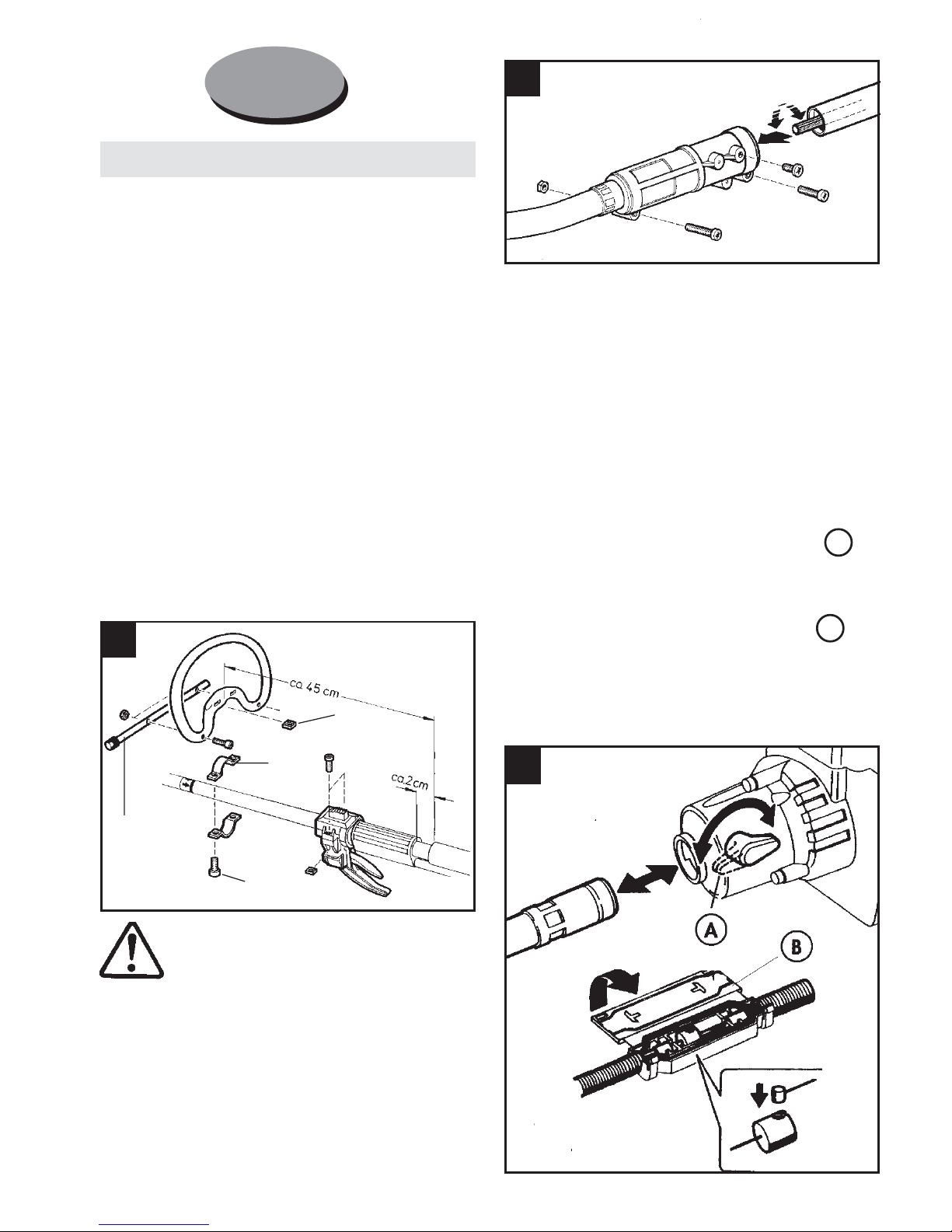
Connect Flex. Shaft, Throttle Cable and
Electrical Cables to Engine Flange
Turn lock lever (11) on engine flange to point
towards shaft. Hold lever in that position.
Insert Flex. Shaft (13) as far as possible and
allow lock lever to move back to lock position.
Open lid of the cable connection (12)
Connect electrical cables. Insert cable into cable
guides, connect throttle
cable and close lid.
Installing loop handlebar
Fasten loop handlebar in front of the throttle handle.
Insert the first handlebar clamp (A) in the grip. Put
the handlebar at the arrow marking on the tube,
then place the second handlebar clamp below on
the tube, insert the nuts M5 (B) into the grip, screw
in the bolts M5x25 (C), and after straightening the
grip, tighten the bolts.
Fasten safety bar (4a) on loop handle with
2 screws.
Attention: For left-handed operators,
the safety bar has to be secured in
the opposite direction.
Assembly
For shipping purposes, the brushcutter is partly
disassembled and has to be reassembled prior to
use.
The brushcutter is only to be used after complete
reassembly.
A
B
Connect Flex. Shaft with Coupling Sleeve
Remove red protection cap from both ends of
flex. shaft (13). Insert flex. shaft into coupling
connector (14) as far as possible and secure with
screw. The square of the flex. shaft has to be
connected to the receiver in the coupling sleeve.
1
2
3
Insert the shaft into coupling connector as far as
possible. Turn the tool while pushing so that the
geared inner shaft fits into the counter part. Insert
the screws and tighten.
4a
C
B
A
GB
Page 8
ATTENTION!
The cable connection must not be under
tension, otherwise the engine will not
run at idle speed. Always take care that
the bowden cable at the carburettor is
not under tension and only moves, when
the throttle is activated. Otherwise there
is a potential danger of running tools.
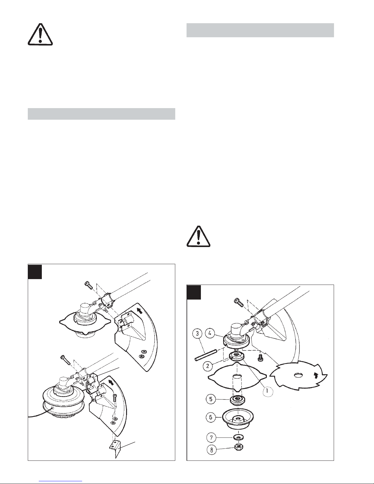
Installing debris shield
With the metal blades of Model 132, the shield
(18) is attached to the shaft tube with two clamps.
The extra long bolts will extend beyond the bottom
of the shield (safety against twisting).
When installing a string head, it is necessary to
insert the connecting piece (A) with two bolts
M5x55 between the lower clamp and the shield.
The extra long bolts will extend beyond the bottom
of the connecting piece (A).
The line limiter (B) is installed on the shield.
Installing and exchanging cutter
Turn arbor shaft (1) with pressure plate (2) so that
the gap for the holding pin (3) matches the gap in
the anti-clogging device (4).
Center the blade onto the disc (5) and place it on
the splined drive shaft (1). Install the nut protector
(6), washer (7), and lock nut (8).
Attention: Left hand thread! (Tighten counter
clockwise).
Place holding pin (3) above anti-clogging-device
(4) on the pressure plate (2). Block shaft and tighten
nut (8) by turning counter clockwise.
The disc (5), nut protector (6), washer (7) and lock
nut (8) are not required when installing a string
head.
The complete string head is screwed on the arbor
shaft (1) against the pressure plate (2) (left hand
thread). With the holding pin (3), the gear shaft
(1) is blocked by way of the pressure plate (2).
Caution! Insert connecting piece (A) on
the shield prior to installing string head.
4
5
A
B
1
Page 9
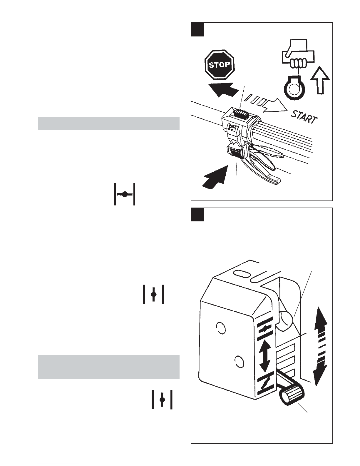
Start-up with Loop handlebar
1. Move stop switch (1) to start position
2. Pull up fully on lever (2)
3. Push in half throttle lock (3), simultaneously
release throttle lever (2)
4. Close choke (5)
5. Push the Primer (6) several times until fuel is
visible in the bulb.
6. Hold the unit by the flange housing with the
left hand. With the right hand, slowly pull
up on the starter grip (8) until resistance is
felt, and then pull quickly and forcefully.
Repeat until the engine „pops“ or attempts
to start.
7. Immediately move choke (5) to
run position! Pull starter grip.
8. Once the engine runs, briefly apply full throttle
(2) and release to return engine RPM to idle
speed.
Start up with warm engine/start up
after brief cut-off.
Leave choke open and start engine.
If engine does not start, activate half
throttle (2). Repeat starting.
6
7
Use only the metal cutting attachments which
have been authorized by SOLO:
Grass-cutting-blade 4 teeth (69 00 706)
Grass-cutting-blade 8 teeth (69 00 693)
Maintenance: When used professionally, we
recommend the flex. shaft be removed daily
from the outer tube and lubricated with
commercially available gear grease.
1
2
3
5
6
Page 10

Declaration of conformity
according to the EG guidelines 89/37 EEC
(altered with 92/31/EEC) and 89/336/EEC.
SOLO Kleinmotoren GmbH, Stuttgarter Strasse 41,
D-71069 Sindelfingen declares sole responsibility that this product,
which this declaration covers, is according to the machinery
guidelines.
Guaranteed Sound pressure Level (DIN45635) 110 dB(A)
Measured Sound pressure Level (DIN45635) 108,5 dB(A)
Sindelfingen, 1stJanuary 2002
SOLO Kleinmotoren GmbH
Hans Emmerich
Executive Director
Page 11

In the best interest of continued technological progress we reserve the right to change design and configuration of any product without prior or other notice. Therefore, please note that text and
illustrations of this manual are not to be considered binding and do not constitute a basis for legal or other claims.
132
SOLO one-cylinder two-cycle engine
30 ccm
1.4 kW (1.9 HP)
9500 1/min
String Head 92,63
Cutting Blade 92,5
String Head 104,55
Cutting Blade 105,68
String Head 2,12/3,72
Cutting Blade 2,8/4,3
Diaphragm carburettor with easy-start
Primer-system
Gasoline-oil-mixture
0,6 l
Gasoline-oil-mixture
Electronic ignition
1.23:1
9.2 kg (20.3 lbs.)
Brushcutter
Engine
Capacity cm
3
Max. capacity with RPM per ISO 8893 kW/min
-1
Max. RPM unloaded w/ brushcutter min
-1
Noise level in work area dB (A)
Sound capacity level per ISO 9207 db(A)
Weighted acceleration value
right handle/left handle m/s
2
Carburettor
Gasoline
Gasoline tank amount liter
Air filter
Ignition
Gear head ratio
Weight without cutters kg (lbs)
Technical Data
Page 12

Im Interesse der ständigen Weiterentwicklung unserer Geräte müssen wir uns Änderungen des Lieferumfangs in Form, Technik und Ausstattung vorbehalten.
Wir bitten auch um Verständnis, daß aus Angaben und Abbildungen dieser Anleitung keine Ansprüche abgeleitet werden können.
In the best interest of continued technological progress we reserve the right to change design and configuration of any product without prior or other notice.
Therefore, please note that text and illustrations of this manual are not to be considered binding and do not constitute a basis for legal or other claims.
SOLO Kleinmotoren GmbH
Postfach 60 01 52
D - 71050 Sindelfingen
Germany
Telefon 07031/301- 0
Fax 07031/301-130
Fax Export 07031/301-149
http://www.solo-germany.com
e-mail: [email protected]
 Loading...