

Page 1

- ENGLISH - Grass trimmer 104L / Brush cutter 107L / 107B
ENGLISH 1
Instruction manual
Original instructions
Caution! Prior to operating the
unit, please read the owner’s manual
carefully, and most importantly, observe
all safety rules.
Observe the maintenance guidelines
closely to ensure the long service life of
your equipment.
Your dealer will be glad to assist you
with any questions.
EC declaration of conformity Î The
EC declaration of conformity on a
separate piece of paper forms part of
these operating instructions.
For USA only:
Emissions Control Warranty Statement
The Environmental Protection Agency and
Solo are pleased to explain the emission
control system on your small non-road
power equipment engine. In the US new
small non- road engines must be
designed, built, and equipped to meet the
Environmental Protection Agency's
standards. Solo must warrant the emission
control system on your small non- road
engine for the period of time listed below
provided there has been no abuse,
neglect, or improper maintenance of your
small non-road engine.
Your emission control system includes
parts such as the carburetor, the ignition
system, and the exhaust system.
Where a warrantable condition exists, Solo
will repair your small non-road power
equipment engine at no cost to you
including diagnosis, parts, and labor.
Manufacturer’s Warranty Coverage
Solo's small non-road power equipment
engines are warranted for a period of two
years. If any emission control related part
on your engine is defective, the part will be
repaired or replaced by Solo.
Contact Information for Authorized Service
Center Locations, Replacement Parts,
Warranty and Technical Information
Warranty repairs must be completed by a
SOLO
Authorized Service Center.
SOLO USA, Inc. 1-800-765-6462
5100 Chestnut Avenue t
techserv@solousa.com
Newport News, VA 23605
Symbols
The following symbols are used in this manual and on the
product:
104L
107L/ B
Thoroughly read these operating
instructions before undertaking any
maintenance, installation and cleaning
steps
Wear ear defenders and a face shield
before starting the engine
Switching off the engine, stop switch on
"STOP"
Wear protective gloves when handling
and working with the equipment
Wear solid shoes, preferably safety shoes
with a good tread
Danger! Failure to comply with the
instructions could cause accidents with
potentially life-threatening injuries
Maintain a minimum distance of 15
metres bystanders
Please note: objects may be thrown out
and high
Please note: power tool may kick back on
contact with a solid object
Never exceed the specified
maximum speed
Never smoke near the power tool or
where the equipment is refuelled!
Keep open flames away from the power
tool and the fuel can
- This equipment produces exhaust fumes
and
- fuel vapours are poisonous;
never start or refuel in enclosed spaces
Fuel mixture: symbol above the fuel
mixture tank cap
Choke flap
:
Cold start position Î choke lever up,
towards this symbol
Operation and warm start Î choke
lever down
---
Model 104L:
Never use metal cutting tools.
Page 2

ENGLISH 2
Index
Page
1. Type plate .................................................................................................................................... 3
2. Safety regulations........................................................................................................................ 3
2.1 Correct use / General safety instructions 3
2.2 Working clothes 4
2.3 Fuelling 4
2.4 When transporting the equipment 4
2.5 Preparing the equipment for starting 5
2.6 Starting 5
2.7 Maintenance and repairs 5
2.8 Working with the machine 6
3. Standard delivery......................................................................................................................... 7
4. Control and function elements ..................................................................................................... 7
5. Preparing the equipment for use .................................................................................................. 8
5.1 Shield installation - model 104L 8
5.2 Fitting the safety end-stop on the loop handle - model 104L 9
5.3 Fitting and replacing the line head - model 104L 9
5.4 Completion - Loop handle - model 107L 10
5.5 Installation - Bike handle - model 107B 10
5.6 Shield installation - model 107L/ B 10
5.7 Assembling and replacing the cutting tool - model 107L/ B 11
5.8 Shoulder strap adjustment - model 107L/ B 13
6. Fuelling............................................................................................................................... ....... 13
6.1 Fuel information 13
6.2 Fuelling 13
7. Starting / Stopping the engine.................................................................................................... 14
7.1 Half throttle start position 14
7.2 Choke and primer 14
7.3 Starting 15
7.4 Turning off the engine: 15
7.5 Engine will not start: 15
8. Using your power tool................................................................................................................ 16
8.1 Scope of Application 16
8.2 Initial use/ start-up behaviour 16
8.3 Correct operating mode 16
8.4 Note on using the nylon line head (available as accessory) 17
9. Parts subject to wear and tear.................................................................................................... 17
10. Operating and maintenance instructions.................................................................................. 17
10.1 General operating and maintenance instructions 17
10.2 Information about the silencer 17
10.3 Sharpening instructions – metal cutting blades - model 107L/ B 18
10.4 Gearbox lubrication - model 107L/ B 18
10.5 Carburettor adjustment 19
10.6 Information about the spark plug 19
10.7 Air Filter Maintenance 20
10.8 Replacing the fuel filter 20
10.9 Shutdown and storage 20
10.10 Scheduled maintenance 21
11. Specification ............................................................................................................................ 22
12. Accessories ............................................................................................................................. 23
13. Guarantee ................................................................................................................................23
In the best interest of continued technological progress we reserve the right to change the design and
configuration of any product without prior notice.
For that reason, no claims can be accepted with reference to text and illustrations in this manual
Page 3

Type plate ; Safety regulations
ENGLISH 3
1. Type plate
2. Safety regulations
2.1 Correct use / General safety instructions
The power tool must only be used to cut grass, reeds, weeds and wild growth at ground level. The power
tool must not be used for any other purposes (see chapter 8.1 "Scope of Application").
Read the operating instructions carefully before placing in service and keep them in a safe
place.
Use this power tool with particular caution.
Non-observance of safety instructions can lead to a risk to life. Also observe any regulations from your
professional body. These operating instructions must always be available at the place of work. All
individuals instructed to work with the equipment (including maintenance, care and repair), should read
these instructions.
• You should request and receive instructions from the vendor on the safe operation if you are using this
type of product for the first time.
• Children and young people under 18 years may not work with this power tool, with the exception of
young people over 16 years of age who are being trained under supervision.
• Keep bystanders and animals away from the working area. Maintain a minimum distance of 15 m.
When working near thickets, be aware that children and animals may be hidden there. Immediately
stop the machine and the cutter if any person or animal comes close to the working area. The operator
is responsible for any accidents or damage caused to parties or property.
• This machine may only be passed on or lent to third parties if they are familiar with the safe use of this
product and with these instructions. Always supply the manual with the machine.
• Ensure you are rested and in good health when using this machine.
• Persons under the influence of alcohol or drugs, including prescription drugs, are not allowed to use
this machine, as their ability to quickly react to potential danger may be impaired.
• Never alter, change or modify any safety equipment or functional assemblies on this machine.
• Only use this machine if it is in good, safe condition. Always check the machine prior to use. Risk of
accident!
• Only use those accessories and attachments that have been supplied by the manufacturer and that
are expressly approved for attachment. When using a nylon head, never replace a plastic line with a
steel line. Always use the appropriate contact protection with each cutter.
• Always stop the engine and remove the spark plug cap when changing cutters to prevent unintentional
starting of the engine.
• The reliability and safe operation of your machine depend on the quality of parts used with the
machine. Only use original spare parts. Original spare parts are identical with genuine production parts
and guarantee best quality in material, dimensions, function and safety. Original parts and accessories
are available from your specialist dealer. Your dealer has been supplied with appropriate
documentation to determine the correct parts. Your dealer is frequently supplied with updates about
improvements to the equipment. Please note that the use of non-original parts will void your warranty.
• Always store the machine in a safe place and in such a way that it will not pose any danger. Stop the
engine when the machine is not used.
Persons who disregard safety instructions, operating or maintenance instructions may be liable for any
damage or consequential losses.
a: Type designation
b: Serial number
c: Build year (08 Î 2008)
Page 4

Safety regulations
ENGLISH 4
2.2 Working clothes
To prevent injuries, always wear suitable clothing and safety equipment when working with this power tool.
This clothing should be practically oriented to the application (for example a tight fitting work suit), but
should not be confining.
We recommend:
SOLO forest and countryside work jacket EN 340 Part no: 99303000 + size (2[s] - 6[xxl])
SOLO Outdoor Knee-breeches Part no: 9902095 + size
or SOLO Outdoor dungarees Part no: 9902094 + size
Never wear scarves, ties, jewellery or other items of clothing, which might get caught in the equipment, in
brush or on branches. Safely tie back long hair (use a cap, helmet or similar).
Wear sturdy shoes with a good tread - ideally safety shoes.
We recommend: SOLO leather forest boots Part no: 9930510 + size (36 - 48)
Wear protective gloves with non-slip palms.
We recommend: SOLO Fit Part no: 9939012 + size.
Use ear defenders and/or a visor for protection against flying objects or objects caught up in the
turbulence (protective goggles for example).
We recommend: SOLO face/ear protection pack Part no: 993901002 (one size)
2.3 Fuelling
Petrol is very light and highly flammable. Keep away from open flames and never spill fuel. Do
not smoke at the operating site or at and near the refuelling site!
• Stop the engine prior to refuelling.
• Let the engine cool down before refuelling - fire risk!
• Open the tank lid slowly to allow any excess pressure in the tank to be reduced without the risk of
petrol spraying out.
• Fuel may contain substances similar to solvents. Prevent products made from mineral oil coming into
contact with skin and eyes. Wear protective gloves during filling with fuel. Frequently change and clean
protective clothing.
• Avoid breathing in fuel vapour.
• The refuelling site should be well ventilated.
• Avoid any soil spillage of fuel or oil (protection of the environment). Use a suitable mat.
• Immediately clean any spilled fuel on the machine. Change contaminated clothing without delay.
• Firmly tighten all tank lids. This will reduce the risk of spillage from lids, which have become loose from
engine vibrations.
• Check for petrol leaks. Do not start the machine or work with the machine if there is a petrol leak. Life
threatening risk from burns!
• Store fuel and oil in approved and correctly labelled containers.
2.4 When transporting the equipment
• Always turn off the engine when transporting the machine.
• Never carry or transport the power tool with the engine running.
• Always cover the cutters with blade protectors, when transporting the equipment over longer
distances.
• To prevent fuel running out and associated damages, secure the equipment against tipping over
during vehicle transportation. Check the tank for leaks. It is advisable to drain the tank before
transportation.
• Drain the tank before despatching the equipment.
Page 5

Safety regulations ; (Packaging and disposal)
ENGLISH 5
2.5 Preparing the equipment for starting
Check the complete machine for operational safety.
• The stop switch should function properly.
• The throttle must have freedom of movement and return to the idle position on its own accord.
• The cutters and contact protection must be tightly secured and in perfect condition.
• Ensure the spark plug cap and the ignition cable are connected firmly. A loose connection may cause
a spark, which can ignite any existing fuel:air mixture - fire hazard!
Should the check reveal any irregularities or recognisable damage (also to the frame), incorrect
adjustments or reduced efficiency of the machine, do not commence work. Take the power tool to a
specialised workshop and have it checked.
2.6 Starting
• Start the machine no less than 3 metres from the refuelling location. Never start the machine in an
enclosed space.
• Ensure that you are standing firmly on the ground when starting. Always start on even ground, with a
firm grip on the power tool.
• Only one person at the time may operate this power tool - no other people should be within a radius of
15 m - even when starting.
• Continue with the starting procedure as described in section 7. "Starting/Stopping the engine".
2.7 Maintenance and repairs
Regularly service this machine. Only carry out those maintenance jobs and repairs, which are described in
this manual. A specialised service centre will carry our all other jobs.
• Do not maintain, repair or store the machine near an open flame.
• Before cleaning, maintenance and repair work, always stop the engine first and pull the spark plug
cap. Exceptions: carburettor and idle adjustments.
• For any repairs only use original parts from the manufacturer.
• Do not modify, alter or change the machine as this may impact on the safe operation of the machine
and may lead to accidents and injuries!
Packaging and disposal
Please keep the original packaging in order to protect the equipment against transport damage in case
you ever need to ship it or transport it. If the packaging materials are no longer required then they must be
disposed of properly in accordance with applicable local regulations. Cardboard packaging materials are
raw materials which can be recycled or reused.
At the end of the equipment’s service life, please make sure that you dispose of it properly, in accordance
with the official directives and regulations that apply in your area.
Page 6

Safety regulations
ENGLISH 6
2.8 Working with the machine
• Only use this power tool when it is complete and in a safe condition.
As soon as the engine is running, the power tool generates toxic gases, which may be invisible and
odourless. Never work with the power tool in enclosed spaces. In confined conditions such pits or
excavations, ensure adequate air changes during work.
Do not smoke at the work site and in the immediate vicinity of the power tool. There is an increased
fire hazard!
• Work conscientiously, thoughtfully and calmly, and do not endanger third parties.
- Pay attention to good visibility and lighting conditions.
- Always remain within earshot of other people who can provide help in case of emergency.
- Plan for timely work breaks.
- Pay attention to possible hazards and take appropriate precautions. Be aware that wearing ear
defenders reduces the ability to perceive noise. This includes sounds alerting to danger such as
signals, shouts, etc. that can go unnoticed.
- Exercise caution when the ground is wet or covered in ice and snow, on overhangs, or uneven
terrain. There is an increased risk of slipping!
- Pay attention to the risk of stumbling and obstacles, such as tree roots and stumps, edges, etc. Pay
particular attention to safety when working on slopes.
- Before commencing work, check the working area for stones, broken glass, nails, wire or other solid
objects and remove such debris to prevent them being picked up and thrown out by the cutters.
- Always hold this power tool firmly in both hands, and ensure your safe and solid foothold.
- Always hold the cutters below hip level. Never lift a rotating cutter off the ground.
- Keep all parts of the body away from rotating cutters.
- Use a correct operating mode (see Chapter 8.3 “Correct operating mode ").
- Use the power tool at lowest possible noise and exhaust levels. Only open the throttle when working,
do not let the engine run unnecessarily. Please note that noise also impacts on the environment.
Observe the quiet times that can vary from place to place.
- Never use blunt cutters and avoid uncontrolled contact of the cutter with debris. Otherwise there will
be an increased risk of the equipment kicking, which could throw the entire machine around. As a
result, the operator could be subjected to involuntary movements, which could lead to serious injury
or death.
• Stop the engine if you notice a difference in the operating characteristics of the power tool.
• Due to the centrifugal clutch, the cutters will run on for a short time, even if you release the throttle.
Ensure the cutter has come to a full stop before storing the machine.
• Always stop the engine before any contact with the cutter – even when clearing a blockage or if cutters
have become jammed – wait until the cutter has stopped and remove the spark plug cap.
• Never touch the exhaust or the silencer; as long as they are still hot, there is a risk of burns!
• Never work with a defective or missing silencer. There is a hazard of hearing damage and burning!
First Aid
A first aid box should always be available on-site. Immediately replace any materials you have used:
Note:
Over exposing persons with circulatory problems to vibrations can lead to damage to their nervous system
or blood vessels. The following systems may occur from vibrations to fingers, hands or the wrists:
Numbness, itching, pain, twinges, changes to the colour of the skin or the skin itself. Seek medical advice
if you experience any of these symptoms.
Page 7

Standard delivery; Control and function elements
ENGLISH 7
3. Standard delivery
• Power tool partially assembled; the following components are supplied separately and require assembly
• Handle subject to model and all parts required to complete the assembly
• Shield
• Cutting tool: (model-specific)
• Tools: combination spanner, retaining pin and screw driver
• Instruction manual, the EC declaration of conformity on a separate piece of paper
•
Model 107L, 107B: all assembly components required for assembling the permitted cutting tools
(accessories),
Shoulder strap
4. Control and function elements
Mod. 104L
Mod. 107B
1 Stop-switch 7 Choke lever 14 Spark plug cap
2 Throttle lever 8 Primer 15 Cutter
3 Gas lever lock 9 Fuel cap 16 Shield
4 Throttle lock 10 Starter grip 18* Protective bar
5* Bicycle handlebar 11 Air filter cover 21 Type plate
6* Loop handle 12* Strap track
*
Depending on the version
Fig. 1
Page 8
Preparing the equipment for use
ENGLISH 8
5. Preparing the equipment for use
For shipping purposes, the power tool is partly disassembled and has to be reassembled prior to use.
Only use the power tool after it has been fully assembled.
Ensure that the tank is fully drained before any assembly, disassembly or modification.
Model 104L
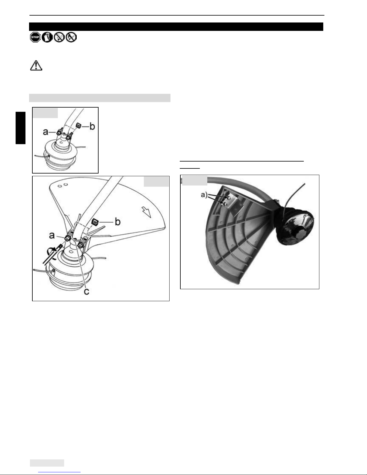
5.1 Shield installation - model 104L
In the pre-assembled
condition, undo both
screws (a) and square
nuts (b).
Leave the remaining
components in their preassembled state.
• Insert square nuts (b) from above on both sides
of the shield.
• Position the shield on the shaft tube so it is
pointing towards the engine.
• Insert fixing screws (a) and tighten evenly.
• Important: The relevant clamp tab (c) must be
fixed in the holes provided on either side of the
shaft tube.
Correct position of the line trimmer on the
shield:
a) The line trimmer must be secured tightly to the
shield using two screws, as shown in the diagram.
Fig. 2a
Fig. 2b
Fig. 2c
Page 9

Preparing the equipment for use
ENGLISH 9
5.2 Fitting the safety end-stop on the loop
handle - model 104L
Always install the safety end-stop (a) on the
operator side of the power tool.
If, during use, you carry the power tool on your r.h.
side, install the safety end-stop in l.h. orientation.
However, if, during use, you carry the power tool
on your l.h. side, install the safety end-stop in r.h.
orientation.
Install the safety end-stop (a) on the loop handle
and secure with the spring clip (b).
The position of the loop handle can be moved
along the shaft tube after loosening screw (c)
(Torx-25), and thus be positioned to suit the height
of the user.
Finally, tighten screw (c), holding the nut opposite
it in place with an open-ended spanner to stop it
turning as well.
In general, before starting work, check the
loop handle and safety end-stop are
seated tightly and correctly.
Model 104L
5.3 Fitting and replacing the line head model 104L
Always switch off the engine, pull the spark
plug cap and wear protective gloves when fitting or
replacing the cutter!
• Carefully place cup washer (a) on drive shaft
(b). Ensure that the edge of the cup washer is
pointing upwards and covers the rim of flange
casing (c).
• Turn the drive shaft with the cup washer until
the hole in the cup washer and the hole in the
flange casing are precisely one above the other.
• Use locking pin (d) to lock the drive shaft.
• Place anti-winding protection (e) (included in
standard delivery of line head) on the cup
washer so the rim of the anti-winding protection
covers the rim of the cup washer.
• Secure line head (f) to drive shaft (clockwise –
standard right-handed thread).
Removing the line head
• Turn the line head until the hole in the cup
washer and the hole in the flange casing are
precisely one above the other and the locking
pin can be inserted.
• Unscrew the line head in an anti-clockwise
direction.
Fig. 3
Fig. 4
Page 10

Preparing the equipment for use
ENGLISH 10
Model 107L/ 107B
5.4 Completion - Loop handle - model 107L
Attach the "loop" handle approximately 5 cm - 30
cm from the strap attachment according to your
preferred working position. The longer side of the
handle serves as a safety barrier and must
therefore always be on the side of the user:
• If you carry the power tool on the right hand
side of your body when working then the longer
side of the handle must face to the left.
• If, however, you prefer to carry the power tool
on the left hand side of your body when working
(i.e. if you are left-handed) then the longer side
of the handle must face to the right.
• Initially tighten the screws only lightly.
• Push the handle, in accordance with your body
size, into its optimum position.
• Then tighten the screws.
5.5 Installation - Bike handle - model 107B
• The r.h. side of handle should be fitted as near
as possible to the handle support.
Note: You will have achieved an optimum
adjustment, if the centre of the power tool is at the
centre of your body. Your elbow should be slightly
angled in operating position.
Important: Always lead the power tool with the
bicycle handlebar on the r.h. side of the body!
5.6 Shield installation - model 107L/ B
• Pull anti-vibration piece (a) with the bead
uppermost (towards the engine) over the shaft
tube. For this, the anti-vibration piece can be
bent open at the slot.
• Insert both square nuts (b) from the inside into
the contact shield.
• Secure shield (c) with both screws (d), both
semi-shells (e) and spacers (f) around the antivibration piece on the shaft tube.
• The rectangular recess of the shield must be
seated precisely around protrusion (g) on the
gearbox.
• Tighten screws (d) alternately and evenly.
Please note: No other mounting position is
acceptable for the shield!
Fig. 6
Fig. 5
Fig. 7
Page 11

Preparing the equipment for use
ENGLISH 11
Model 107L / 107B
5.7 Assembling and replacing the cutting tool - model 107L/ B
Always switch off the engine, pull the spark plug cap and wear protective gloves when fitting or replacing
the cutter!
Subject to model version, a line head or metal cutting blade (4-tooth grass cutting blade / 3-tooth brush
cutting blade) is included as the cutting tool in the standard delivery of your power tool.
A) Assembly of the nylon line head
• Fit the anti-winding protection (30) (supplied
with the line head) after the pressure piece (25).
The side of the anti-winding protection labelled
with the number "871" faces the gearbox, so
the edge of the anti-winding protection overlaps
the edge of the bevel gearbox.
• Block the shaft with the pin (29).
• Screw on the line head by hand. Caution: left-
handed thread.
• •Fit the line cutter blade (32) with screw (33)
and washer (34) to the protective bar (31).
• Fit the protective bar (18) with assembled line
trimmer from underneath onto the guard. Bend
the protective bar slightly in the process.
Important:
When using the line head, never
start the power tool without the protective bar
and the line trimmer assembled.
If the length of the line has been adjusted (see
chapter 8.4, "Adjusting the cutting line"), the line
trimmer will automatically cut the ends of the line
to the correct length during operation.
When using metal cutting blades, always
work without the protective bar fitted.
B) Assembling metal cutting blade
• Position the power tool with the output shaft
facing upwards.
• Place the brush cutting blade on the pressure
piece (25). In order to centre the cutting blade,
the shoulder of the pressure piece must be
located exactly in the bore of the cutting blade.
• Fix the pressure washer (26).
• Place the nut protector (27) and turn safety nut
(28) onto the shaft.
Caution! Left hand thread - tighten counter
clockwise.
Take care that all parts are centered.
• Block the shaft with the stop pin (4) and tighten
nut.
It is imperative that the safety nut (28) is
replaced, if it has become loose due to
frequent rem oval and tightening.
Afterwards check that the cutting blade is securely
seated and that it is properly centred.
Fig. 8
Fig. 9
Page 12

Preparing the equipment for use
ENGLISH 12
Model 107L/ 107B
Transport protection for metal cutting blades
(model 107L/ B)
When you first purchase an approved metal
cutting blade which is not supplied together with
the power tool (see chapter 12 "Accessories"), you
will also need to purchase a corresponding
transport protector.
When the metal cutting blades are attached (4tooth grass cutting blade or 3-tooth brush cutting
blade, provided either as standard equipment with
the different models or purchased as accessories),
the transport protector must always be attached to
cover the blades when the device is being stored
or transported, or during work breaks during which
the engine is switched off.
• Position the transport protector with the
corresponding recess at one of the tips of the
metal cutting blade.
• Press the two tabs (a) on the transport protector
together to increase the internal diameter of the
transport protector.
• Lay the transport protector right over the cutting
tool. Position the inner shoulder (b) between the
metal cutting blade and the running disc.
• Open the two tabs again, and in doing so also
position the inner shoulder between the metal
cutting tool and the running disc at tab (c).
When restarting work, take the transport protector
back off by pressing the two tabs (a) together
before starting the engine.
Dismantling the cutting tool
(model 107L/ B)
• With the engine off, turn the cutting tool until the
recess in the cup washer and the hole in the
gearbox casing are precisely one above the
other, and the locking pin can be inserted.
• Unscrew the cutting tool in an anti-clockwise
direction (left-handed thread).
[For metal cutting tools, undo the locking nut
using a suitable tool; for the line head, unscrew
directly by hand.]
Fig. 10
Page 13

Preparing the equipment for use; Fuelling
ENGLISH 13
Model 107L / 107B
5.8 Shoulder strap adjustment
- model 107L/ B
Before commencing work, adjust the shoulder
strap and handle according to the operator’s body
size.
Wear the single shoulder strap over the opposite
shoulder to the side on which you are carrying the
power tool. Once the length of the strap has been
correctly adjusted the strap hook should be over
your hip. Hook the strap hook into the strap
attachment on the power tool.
Balance the power tool and attached cutting blade
so that the cutting tool hovers just above the
ground when your hands are off the attached
power tool.
If the cutting tool hovers more than 30 cm above
the ground, the strap must be secured closer to
the engine.
If the tool lies on the ground, the strap must be
secured further from the engine.
To do this on
model 107L
, undo the two screws
and move the strap holder along the shaft
accordingly
For
model 107B
, hook the strap hook into
another, corresponding fixing hole on the strap rail.
If necessary, the entire bike handle unit with the
strap rail can be slightly moved by undoing the
four screws on the shaft.
As a general principle, check that all screws are
seated tightly before starting work.
(schematic diagram)
6. Fuelling
6.1 Fuel information
A high performance two-stroke engine
operated with a petrol:oil mixture (petrol + oil
= fuel mixture) or with a special fuel mixture for
two-stroke engines available from specialists
powers this machine.
We recommend the proprietary “Aspen 2-takt”
special fuel mixture. Please observe the special
fuel manufacturer’s instructions.
Information on individual mixing of the fuel mixture
Normal or super unleaded petrol can be used for
individual mixing purposes (minimum octane
number 92 RON).
When using a particularly high quality proprietary
2-stroke engine oil such as the “SOLO Profi 2T-
Motoröl” which we supply, we recommend an
oil:petrol mixing ratio of 1:50 (2%).
When using other brands of 2-stroke oil we
recommend a mixing ratio of 1:25 (4%).
Only use proprietary 2-stroke engine oil!
Never store fuel mixture longer than 3 - 4 weeks.
Fuel mixture table
Oil in litres
Petrol in
litres
SOLO 2T
engine oil
2% (50 : 1)
Other two-
stroke oils
4% (25 : 1)
1 0.020 0.040
5 0.100 0.200
10 0.200 0.400
Unsuitable petrol or deviations in the mixing ratio
may lead to serious engine damage!
Avoid direct skin contact with petrol and
avoid inhaling petrol fumes - health hazard!
6.2 Fuelling
While fuelling always follow all safety instructions
and take all safety precautions.
Handle fuel only with the engine turned off.
Carefully clean the area around the filler inlet.
Place the machine with the fuel inlet pointing
upwards. Unscrew the tank lid and fill the fuel
mixture up to the lower edge of the filler neck. Use
a funnel with filter to prevent tank contamination.
After filling the tank replace the tank lid and tighten
firmly.
Fig. 11
Page 14

Starting / Stopping the engine
ENGLISH 14
7. Starting / Stopping the engine
7.1 Half throttle start position
A) Models with a "loop" handle (104L and 107L)
• Slide the stop switch (1) into the operating
position.
• Grip the handle; the safety locking key (3) is
activated via the grip area, which also enables
throttle lever (2) to be regulated.
• Press throttle lever fully down.
• Press the half throttle lock (4), and let the
throttle lever return, whilst holding the half
throttle lock in.
B) Models with a "bike" handle (107B)
• Grip the handle; the safety locking key (3) is
activated via the grip area, which also enables
throttle lever (2) to be regulated.
• Press throttle lever fully down.
• Whilst holding the throttle lever down, move
stop switch (1) towards "Start"
( ), and
release the throttle lever.
The part throttle stop is cancelled by brief
operation of the throttle control. The stop switch on
the bike handle then jumps to the central position
Î operating position.
7.2 Choke and primer
Adjust choke as follows:
• With a cold engine, position choke lever (7) up
towards "Close"
.
• With a warm engine, position choke lever (7)
down.
When first starting or if the fuel tank has been
completely drained and has been refilled, press
primer (8) several times (at least 5x) until the fuel
is visible in the plastic bulb.
Fig. 14
Fig. 13
Fig. 12
Page 15

Starting / Stopping the engine
ENGLISH 15
7.3 Starting
Observe the safety instructions when starting.
(schematic diagram)
Lay the power tool level and without obstructions
on the ground.
During starting, never stand or kneel on the shaft
tube, otherwise the shaft or the tube might be
damaged.
Take up a safe position, securely hold the machine
and ensure that the cutter does not touch any
objects or the ground.
When the engine is cold:
With the choke lever up (
) start the engine by
pulling the starter handle up in a straight line
several times until the engine is briefly audible
(ignition).
Then immediately move the choke lever down.
Continue to start until the engine runs evenly.
When the engine is warm:
With the choke lever down start the engine by
pulling the starter handle up in a straight line
several times until the engine runs evenly.
If the engine is running in part throttle operation:
,
briefly pull the throttle back to release the half
throttle detent. Release the throttle lever again to
allow the engine to run at idle speed. Now you can
commence working.
The following instructions are aimed at increasing
the service life of the starter rope and of the starter
mechanism:
• Always pull the rope out in a straight line.
• Do not let the rope drag across the edge of the
rope eyelet.
• Do not pull rope all the way out - risk of the rope
breaking.
• Always manually guide the rope back into its
start position with your hand on the starter grip do not let it retract on its own.
A specialist can replace a damaged starter rope.
Note: Under good conditions, the engine will
already start under idling throttle if it is at operating
temperature. (If a part throttle stop is set it will be
cancelled by operation of the throttle control even if
the engine is at standstill.)
Starting with the stop switch in run-position
If the engine will not start under idling throttle, set a
part throttle stop in the way described above.
7.4 Turning off the engine:
Release the throttle and push the stop switch to
”STOP”.
Important: Due to the centrifugal clutch, the cutter
will run on for a short time, even if you release the
throttle. Ensure the cutter has come to a full
standstill before storing the machine.
7.5 Engine will not start:
If the engine fails to start after several attempts,
check whether all adjustments described above
have been correctly carried out, particularly that the
stop switch is not in the "STOP" position. Try
starting once again. The combustion chamber will
be flooded, if the engine still fails to start.
In that case we recommend you proceed as
follows:
Stop switch on "STOP"
• Remove the spark plug cover.
• Pull the spark plug cap off the spark plug.
• Remove the spark plug and dry fuel mixture
from the electrodes.
• Move the throttle lever up to full throttle. Pull the
starter handle several times (with removed
spark plug) to clear the combustion chamber.
• Move the throttle lever down to idling position,
refit the spark plug, the plug cap and the plug
cover.
• Then:
- Position choke lever down ("warm start")
- Slide stop switch into operating position
- Lock the throttle lever at half throttle
- Turn on engine.
Fig. 15
Page 16

Using your power tool
ENGLISH 16
8. Using your power tool
8.1 Scope of Application
Only use power tools equipped with a nylon head
(subject to model) for cutting grass – particularly
suitable around obstacles - and for trimming light
weeds and wild growth near ground level. The
nylon head is particularly suitable for a soft cut,
e.g. for clean trimming around trees and posts.
Use power tools equipped with the grass cutter
blade (accessory 107L / 107B) only for cutting
grass away from obstacles and for cutting stronger
weeds and wild growth near ground level.
Only use power tools fitted with the 3-tooth brush
cutting blade (accessory 107L / 107B) for mowing
grass, light brush, reeds and uncultivated growth
at ground level.
Never use the power tool for any other purpose.
8.2 Initial use/ start-up behaviour
When switching on the engine for the first five
times prior to commencing work, first operate for a
short time in the mid-speed range without any load
until the engine has warmed up a little.
8.3 Correct operating mode
Observe the relevant safety instructions when
using the power tool.
Approach the working area with the power tool set
to idle, and then switch to full throttle. Never leave
the engine running at high speed without applying
a load.
(Diagram: 3-tooth brush cutting blade -
model 107)
Dip the tool from the r.h. side 2/3 into the material
to be trimmed. Then work the power tool like a
scythe, i.e. by moving forward step by step, whilst
cutting from right to left.
Operate the power tool at full throttle to obtain an
optimum cutting result. Never operate with the
clutch in slipping range. Consequential damage
through excess loads or overheating is excluded
from our warranty.
Immediately stop the engine in case of noticeable
vibrations or when material has gathered around
the cutting tool or contact shield. Slow down the
cutting tool by pressing it onto the ground, until it
has come to a complete standstill. Pull the spark
plug cap from the plug, and clean the tool seat of
all grass, roots etc. Check the entire power tool for
perfect condition.
Fig. 16
Page 17

Using your power tool; Parts subject to wear and tear ;Operating and maintenance instructions
ENGLISH 17
8.4 Note on using the nylon line head
(available as accessory)
When using the nylon head, always ensure that
you operate only with the correct length of line.
When the contact shield is fitted, the line will
always be trimmed to the permissible length
automatically (a line trimming blade is fitted into
the shield). There is a high risk of injury, and the
engine is subjected to excessive loads leading to a
risk of damage, if nylon lines are left too long.
Important:
If using the line head, never start
the power tool without having fitted a line
trimmer blade.
Adjusting the cutting line
When using a semi-automatic nylon head:
(schematic diagram)
Whilst the power tool is running without load, but
with rotating nylon head, lightly push the nylon
head several times onto ground with growth cover.
The cutting line will be dispensed in stages. With
each action, approx. 30 mm line will be dispensed.
The line trimming blade will correct any excess
length.
When the cutting line is fully spent, you can
replace it with line available
Ø 2.4 mm under part no. 6900942 (accessory).
9. Parts subject to wear and tear
Various parts are subject to application-specific or
normal wear and must be replaced in good time,
when required. The following parts are subject to
normal wear and are not covered by the
manufacturer's guarantee:
• Air filter
• Fuel filter
• All rubber parts which come into contact with
fuel
• Clutch
• Spark plug
• Starter
• Cutting tools
10. Operating and maintenance instructions
10.1 General operating and maintenance
instructions
The maintenance and the repair of modern
machines as well as their safety-relevant
assemblies require qualified specialised training
and a workshop equipped with special tools and
test equipment. Consequently the manufacturer
recommends that all tasks not described in these
operating instructions be carried out by a
specialised workshop. That specialist has the
required training, experience, and equipment at his
disposal, to provide you with the most costeffective solution for such work. He will provide
additional help in word and deed.
After a running-in time of app. 5 hours, all
accessible screws and nuts (except the carburettor
adjusting screws) must be checked for tightness
and they must be retightened, if required.
Check the cutter regularly and whenever you
notice any irregularities, or when the cutter/contact
shield becomes blocked. For this, switch off the
engine and wait until the cutter has come to a
complete standstill. Pull the spark plug cap, and
remove grass, debris, etc. from the cutter support.
Immediately replace blunt or damaged tools, even
if they display only small cracks – do a ”ping” test.
It is best to store the equipment in a dry, safe
location with a full fuel tank. There should be no
open flame or similar nearby. When not using the
equipment for longer periods, (longer than four
weeks), see chapter “10.9 Shutdown and storage”.
10.2 Information about the silencer
Your engine appliance has reduced exhaust
emissions which are considerably lower than the
statutory limits. The silencer creates a great deal
of heat during operation as a result. Do not touch
the silencer whilst it is still hot. Discolouration of
the outer silencer housing is quite normal.
Fig. 17
Page 18

Operating and maintenance instructions
ENGLISH 18
Model 107L/ 107B
10.3 Sharpening instructions – metal cutting
blades - model 107L/ B
(Diagram: 3-tooth brush cutting blade)
When the blades become slightly blunt, sharpen
the edges of the cutting tips with a flat file at a 30°
angle.
For the 3-tooth brush cutting blade, file the
edges from both sides; for the 4-tooth grass
cutting blade, file only from one side.
All cutting edges need to be filed back equally, if
the wear and tear is substantial, or if there are
broken-off cutting edges. It is necessary to check
for imbalance and if necessary, to make
corrections by additional filing. The sharpening
angle is 30°.
For the 3-tooth brush cutting blade, your dealer
offers a sharpening jig (part no.: 0080548) to help
with sharpening.
10.4 Gearbox lubrication - model 107L/ B
To lubricate the bevel gear drive, use SOLO
"Special gearbox grease" (part no. 008318025).
Check the grease level weekly and top up, if
required (approx. every 20 - 50 hours).
Remove the filler plug from the side of the gearbox.
If no grease is visible inside, top up with grease
(top-up quantity approx. 5 – 10 g).
Replace and tighten the filler plug.
Please note: Do not overfill with grease, as that
may lead to the gearbox overheating. Never fill the
gearbox casing to the top with grease.
Tip: If required, top up with a maximum of 5g
grease. It is preferable to check more frequently
(e.g. before you start working) whether grease is
still visible.
Your SOLO dealer workshop is happy to help you
in case of doubt.
Fig. 19
Fig. 18
Page 19

Operating and maintenance instructions
ENGLISH 19
10.5 Carburettor adjustment
The carburettor is adjusted at the factory for
optimum performance. Subject to the place of use
(mountains, low-lying areas), the average idling
speed given in the specification can be adjusted
as follows, via the idling end-stop screw "T" (the
use of a rev counter is recommended):
• If the idling speed is too high, turn the idling
end-stop screw "T" anti-clockwise.
• If the idling speed is too low (engine stops)
turn the idling end-stop screw "T" clockwise
until the engine runs smoothly.
With the throttle set to idle, the cutting tool
must not, under any circumstances, rotate!
If the idling speed cannot be set correctly with the
idling end-stop screw "T", request an authorised
service centre to tune the carburettor.
The adjusting screws for the idling mixture "L"
and the full-load mixture "H" must only be
adjusted by an authorised workshop.
The following instructions are for authorised
service shops
Use the D-CUT carburettor key to adjust the idle
mixture screw "L" and the full load mixture screw
"H".
Ask the specialist workshop that is part of our
customer service about standard settings, or visit
our internet portal for dealers at www.part-andmore.org.
Clean the air filter before adjusting the low speed
screw!
Let the engine run warm before adjusting the
engine speed.
The carburettor is tuned for optimum engine
performance. Use a rev counter to tune the
carburettor correctly!
Do not adjust the engine to a higher speed.
Excessive engine speed can lead to major engine
damage!
10.6 Information about the spark plug
Check the spark plug regularly
after 50 hours of operation.
Removing the spark plug:
• Press the top tab of the spark plug cover (16) down
(a), push back (b) and remove.
• Remove the spark plug cap below this.
• Remove spark plug using the combination spanner
and dry thoroughly.
When the spark plug has been removed or the
ignition cable has been pulled out of the plug cap, the
engine must not be moved. There is a risk of fire
through sparks.
Checking the spark plug:
• Clean spark plug with a dry cloth and check
electrodes. There must not be any dirt between the
electrodes. Brush dirt out with a thin paintbrush if
necessary.
• If the electrodes have been heavily worn away,
replace the spark plug immediately – otherwise
after 100 hours run.
• The correct electrode gap is 0.5 mm. If the
electrodes are bent and the electrode gap is
incorrect, replace the spark plug.
• Before starting work, check ignition cable for
perfect connection and insulation.
The permissible spark plug (interference-free, energy
value 240) is available under the following
description:
BOSCH USR 4 AC
Fitting the spark plug:
• Refit the spark plug and tighten using the
combination spanner (recommended torque if
using a torque spanner Î 10 Nm).
• Always push the spark plug cap firmly onto the
spark plug.
• Position spark plug cover (16) on casing and push
on until it clicks back into place.
Fig. 21
Fig. 20
Page 20

Operating and maintenance instructions
ENGLISH 20
10.7 Air Filter Maintenance
Contaminated air filters cause a
reduction in engine performance and increase fuel
consumption with more pollutants in the exhaust
gas. Engines are less likely to start readily with a
contaminated air filter.
As a basic principle therefore, the air filter should
be cleaned as follows before starting work, and
intermittently in very dusty conditions:
Before opening the air filter, close the choke to
prevent dirt entering the carburettor.
• Push tab (a) in, only slightly open air filter lid
(11) and remove by rotating gently back and
forth
• Remove foam filter (c) from the lid and clean
the area around the filter.
• Thoroughly clean air filter casing (d) and air
filter cover (11) on the inside, using a
paintbrush or by carefully blowing on them.
• Clean filter insert (c) by shaking it out or
carefully blowing on it.
If the filter insert is damaged or so contaminated
that it is impossible to clean, replace it with the
original spare part (part no. 20 48 406).
• Insert the new or cleaned foam filter into the air
filter lid.
• Position the air filter cover with both tabs (b)
[inside, opposite tab (a)] in the corresponding
two pockets (b’) of the filter casing.
• Press air filter cover against the filter casing
until tab (a) clicks audibly into place.
10.8 Replacing the fuel filter
We recommend having the fuel filter (34) changed
annually by a specialised service centre.
(schematic diagram)
A trained mechanic can carefully remove the fuel
filter via a wire loop through the fuel tank filler.
Ensure that the thicker part of the fuel hose on the
tank wall is not drawn into the fuel tank.
10.9 Shutdown and storage
Clean the power tool after use.
• Never use aggressive cleaning solutions or
those containing solvents to clean any part of the
engine. Never hose down the engine. For best
results, simply wipe down the entire engine with
a dry or slightly damp cloth.
• Clean leftover cuttings off the blades using a
small brush.
• Ingrained plant remains on the blades can be
removed with the
"SOLO Universal Cleaner"
(part no.: 00 83 116). Leave it to work for a short
time, then residues become soft and partially
dissolve, and can be wiped off with a cloth.
• To prevent corrosion, we recommend treating
metal cutting tools with the
"SOLO Maintenance
and Care Oil
" (part no.: 00 83 163).
Store the device in a dry, safe location inside a
building (garage, basement, …). There must not be
any open fires or similar nearby. Ensure that the
device cannot be used by unauthorised persons,
especially children.
If not in use for more than four weeks, drain the
fuel tank in a well ventilated location before storing.
Start the engine with an empty fuel tank and drain
the carburettor until the engine stops. Oil residues
from the fuel mixture could otherwise clog the
carburettor jets and make it difficult to start the
device later.
Fig. 23
Fig. 22
Page 21

Operating and maintenance instructions
ENGLISH 21
10.10 Scheduled maintenance
The following information is based on standard operating conditions.
For special conditions, such as prolonged daily use, the recommended
maintenance intervals should be reduced accordingly.
Implement all maintenance jobs regularly. If required, authorise a specialist
service centre to maintain the machine for you. The owner of the machine is
responsible for:
• Any damage caused by a lack of maintenance, incorrect or late
maintenance and repairs
• Consequential losses - including corrosion - from incorrect storage
after the first 5 hours
before starting work
weekly
after every 50 hours
after every 100 hours
as required
before the start of the mowing season,
or once per year
Check idling speed
X
Carburettor
Adjust idling speed
X
Clean
X
Air filter
Replace
X
Check electrode gap and replace spark
plug if required
X X
Spark plug
Replace
X X
Check
X X
Gearbox lubricant
Top up
X X X
Check
X
Sharpen
X
Metal cutting blades
- model 107L/ B only
Replace
X
All accessible screws
(except for adjusting screws)
Retighten
X XX
Controls
(stop switch, throttle lever, half
throttle detent, starter)
Check function
X
Silencer
Visual inspection
X
Visual inspection
X
Complete machine
Clean
X X X
Furthermore, as part of the annual service at an authorised dealer, request the following services:
• Complete check of the entire machine
• Professional cleaning of the engine (fuel tank, cylinder head fins, …)
• Check and, if necessary, replace wearing parts, particularly the annual fuel filter change
• Optimum setting of the carburettor
Page 22

Specification
ENGLISH 22
11. Specification
Gras trimmer / Brush cutter 104L 107L 107B
Engine type SOLO single cylinder two-stroke engine
Engine capacity cm3 25.7
Bore / stroke mm 33 / 30
Engine power kW at rpm 0.7 / 7 500
Max. permissible speed
no load with cutter
Nylon head rpm
Grass cutter blade rpm
8 500 ± 200
---
8 500 ± 200
9 000 ± 200
Medium idling speed rpm 3 000 ± 200
Fuel tank capacity l 0.5
Fuel consumption at max. power
(ISO 7293) kg/h
320
Specific consumption at max. power
(ISO 7293)
g
/
kWh
460
Clutch engagement speed rpm 4 700
Fuel mix ratio:
with SOLO 2T engine oil
with other two-stroke oils
1:50 (2%)
1:25 (4%)
Carburettor All-position diaphragm carburettor with primer and
integrated fuel pump
Air filter Foam filter
Ignition Electronically controlled magneto ignition, maintenance free
--- 1.23 : 1 Gear reduction Î
Max. speed of the cutter rpm
8 500 ± 200 7 300 ± 200
Shaft tube - connectionØ mm
Drive shaft Ø mm
Serration
24
6, flex
M7;
24
7
Star serration 7 teeth
Dimensions Height mm
Width mm
Length mm
34
37
158
30
38
187
50
67
187
Weight kg
w/o shield and cutter
4.9 5.8 6.2
In determining the following values regarding the acceleration of vibrations and sound, the different
operating conditions were weighted in accordance with the current standards.
Weighted effective acceleration a
hv,eq
(DIN ISO 22867)
Handle r.h. side / handle l.h. side
Nylon head m/s
2
Grass cutter blade m/s2
9.3 / 7.4
---
5.7 / 4.8
7.1 / 5.9
4.2 / 4.2
6.3 / 8.3
Sound pressure level L
Peq
(EN ISO 22868)
Nylon head dB(A)
Grass cutter blade dB(A)
92
---
93
94
93
94
Sound power level L
Weq
(EN ISO 22868)
Nylon head dB(A)
Grass cutter blade 4 teeth dB(A)
103
---
103
104
103
104
Page 23

Accessories ; Guarantee
ENGLISH 23
12. Accessories
Via dealers, SOLO offers an extensive range of grass trimmer / brush cutter accessories. Their use is
limited to the particular model to which it is allocated, together with its relevant protection. Orientate
yourself on the following table and check with your dealer.
Model
Accessory Protection Part no.
104L
107L/B
2 nylon head semi-automatic M 10 x 1.25 RE
(grass, even around obstacles, light weeds)
Standard shield +
line trimming blade
69006505 X
2 nylon head semi-automatic M 10 x 1.25 LI
(grass, even around obstacles, light weeds)
Standard shield +
line trimming blade
69006375 X
Replacement line for nylon head 15m, Ø2.4 mm 6900942 X X
Spool of nylon cord 90 m, Ø2,4 mm 0063201 X X
Grass cutter blade 4 teeth, Ø230 mm
(grass, stronger weeds)
Standard shield
without protective bar
6900948 X
Brush blade 3 teeth Ø250 mm
(bushes, reeds, tough grass)
Standard shield
without protective bar
6900947 X
Transport protector for metal cutting blades up to
Ø250 mm
6073534 X
High performance gearbox grease 008318025 X
SOLO 2T engine oil 100 ml 0083103 X X
SOLO 2T engine oil 1 l 0083104 X X
SOLO 2T engine oil, in a metering bottle 1 l 0083105 X X
SOLO face/ear protection pack 993901002 X X
SOLO forest and countryside work jacket EN 340 99303000 + size (2[s] - 6[xxl]) X X
SOLO Outdoor Knee-breeches 9902095 + size X X
SOLO Outdoor dungarees 9902094 + size X X
SOLO leather forest boots 9930510 + size (36 - 48) X X
Gloves SOLO Fit 9939012 + size X X
13. Guarantee
The manufacturer guarantees trouble-free quality and will cover the cost of replacing parts which are found
to be faulty in material or workmanship within the prescribed guarantee period after the date of purchase.
Please note that specific guarantee conditions may vary from country to country. If in doubt, ask your
equipment vendor. He is responsible for guarantee matters.
We hope you will understand that we cannot be liable for damage resulting from the following causes:
• Non-compliance with the operating instructions.
• Neglecting essential maintenance and repair work.
• Damage caused by incorrect carburettor adjustment.
• Wear in normal use.
• Obvious overload by continuously exceeding the maximum performance limit of the product.
• Using non-authorised tools.
• Use of force, incorrect treatment, misuse and accidents.
• Damage from excessive heat due to dirt build-up around the cooling fan housing.
• Attempted adjustments and repairs by unqualified persons.
• Use of unsuitable spare parts or third party parts, if these are the cause of the defect.
• Use of unsuitable or stale fuel.
• Damage caused by using the product in the hire or rental industry.
Normal cleaning, adjustments or maintenance work fall outside the guarantee provisions.
A service centre authorised by the manufacturer must carry out all guarantee work.
Page 24

SOLO
Postfach 60 01 52
D 71050 Sindelfingen
Tel. 07031-301-0
Fax 07031-301-130
info@solo-germany.com
SOLO
P.O.Box 60 01 52
D 71050 Sindelfingen
Germany
Phone+49-7031-301-0
Fax +49-7031-301-149
export@solo-germany.com
 Loading...