

Page 1
The Sollatek
PowerBack PB3000S / PB5000S
Inverter With Solar Charger Controller
User Instructions
the power to protect
Important: This manual contains important safety instructions.
Keep this manual handy for reference.
• Before using this product please read all instructions carefully.
• Keep these instructions for future reference.
• All specifications are subject to change without prior notice.
Page 2

Important Safety Warning
WARNING:
This chapter contains important safety and operating
instructions. Read and keep this User Guide for future reference.
General Precautions
1. Before using the unit, read all instructions and cautionary markings on:
(1) The unit (2) the batteries (3) all appropriate sections of this manual.
2. CAUTION --To reduce risk of injury, charge only deep-cycle lead acid type
rechargeable batteries. Other types of batteries may burst, causing personal
injury and damage.
3. Do not expose the unit to rain, snow or liquids of any type. The unit is
designed for indoor use only. Protect the unit from splashing if used in vehicle
applications.
4. Do not disassemble the unit. The maintenance information is only for
service technicians. When service or repair is required, contact your
supplier for further arrangements. Incorrect re-assembly may result in a
risk of electric shock or fire.
5. To reduce risk of electric shock, disconnect all wirings (AC mains, batteries,
solar panel) before attempting any maintenance or cleaning. Turning off the
unit might not eliminate the risk.
6. No terminals or lugs are required for hook-up of the AC wiring. AC wiring
must be no less than 10 AWG gauge copper wire and rated for 75oC or
higher.(Refer to equivalence table on page 10). Battery cables must be rated
for 75oC or higher and should follow the recommendation in the manual.
Crimped and sealed copper ring terminal lugs (refer to INSTALLATION
section) should be used to connect the battery cables to the DC terminals of
the unit. Soldered cable lugs are also acceptable.
7. Be cautious when working with metal tools on, or around batteries. Dropping
a tool and short-circuit the batteries or other electrical parts may result in
sparks and explosion.
8. No AC or DC disconnects are provided as an integral part of this unit.
Both AC and DC disconnects must be provided as part of the system
installation. See INSTALLATION section of this manual.
Page 3

9. No over current protection for the battery supply is provided as an integral part
of this unit. Over current protection of the battery cables must be provided as
part of the system installation. See INSTALLATION section of this manual.
10. GROUNDING INSTRUCTIONS -This battery charger should be connected to
a grounded permanent wiring system. For most installations, the Ground
Lug
should be bonded to the grounding system at one (and only one point) in the
system. All installations should comply with all national and local codes
and
ordinances.
11. The unit must be installed and maintained by qualified staff. Please read the
manual carefully before installations & operations.
12. The unit contains energy source: the batteries and solar. All terminals
and
sockets may be powered even when the unit is not connected to the mains.
Page 4

Table of Content
1.# Overview#.......................................................................................................#1#
1.1# Key#Feature#..................................................................................................#1#
1.2# Product#Outlook#..........................................................................................#2#
1.3# Basic#System#Architecture#...........................................................................#3#
2.# INSTALLA T ION#...............................................................................................#4#
2.1# Unpacking#and#Inspection#...........................................................................#4#
2.2# Remove#bottom#cover#................................................................................#4#
2.3# Placement#...................................................................................................#4#
2.4# Battery#Connection#.....................................................................................#5#
2.5# AC#Connection#............................................................................................#7#
2.6# PV#connection#.............................................................................................#9#
3.# OPERATION#.................................................................................................#11#
3.1# LCD#display#introduction#..........................................................................#11#
3.2# LCD#display#setting:#..................................................................................#15#
3.3# Standby#Charging#Mode#...........................................................................#15#
3.4# Operation#Modes#(after#powered#on)#.....................................................#16#
3.5# Fault#Mode#...............................................................................................#19#
4.# SPECIFICATION#............................................................................................#19#
APPENDIX#A#.....................................................................................................#25#
APPENDIX#B#.....................................................................................................#28#
Page 5

1. Overview
This is a pure sine wave stand-alone inverter/charger system combining the
function of inverter, solar charger and AC charger, and provides a l
ong
run-time uninterruptible power supply. Its comprehensive LCD display
provides system status, and allows users to set output source priority, charger
source priority, charger current and so on.
1.1 Key Feature
• High-frequency switching technology for compact size and light weight
• Pure sine wave output for wide range of applications and harsh
environment
• Build-in solar charger controller with MPPT technology to optimize the
power utilization
• High efficient DC-to-AC conversion minimizing energy loss
• Standby Charging Mode enables battery charging even when the unit is
switched off
• Intelligent cooling fan control
• Input/output isolated design for the maximum operation safety
• LCD displays comprehensive operation status
• Configurable output source priority, charger source priority, charger
current and so on.
• Supports Home Appliances / Office Equipment/ Lighting Equipment/
Motor-based Equipment (such as Fan, Air-Conditioner, Washing
Machines)
• Thorough protections: Input low voltage / Overload / Short circuit / Low
battery alarm / Input over voltage / Over temperature/SCC over current
protection
• Rack design & wall-mounted design for flexible installation
Page 6
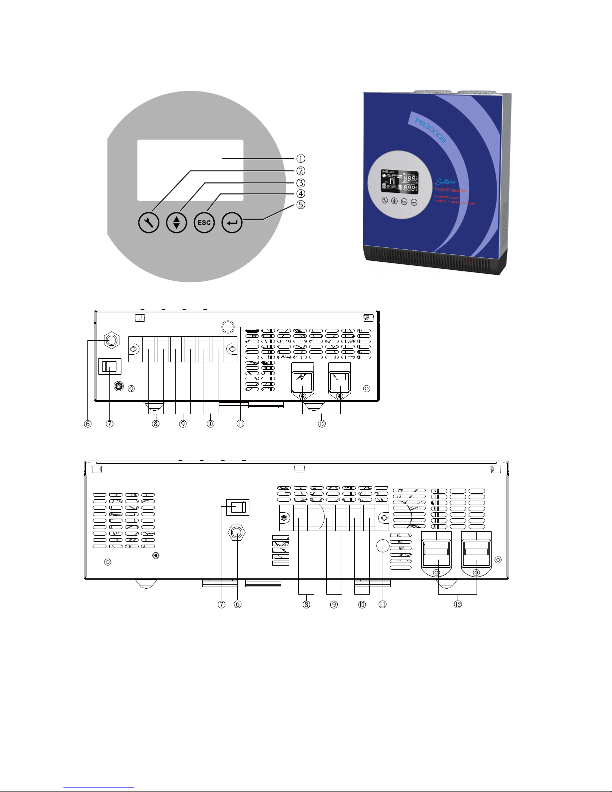
1.2 Product Outlook
3
K rear panel
5
K rear panel
1. LCD display
2. LCD Configuration button: Enter configuration mode, and switch between
setting menus
3. LCD up/down button: Move to previous/next setting option
4. LCD ESC button: Return to main menu
Page 7
5. LCD Enter button: Confirm setting
6. AC input circuit breaker
7. Power ON/OFF switch
8. PV input
9. AC input
10. AC output
11. AC Input & output GND
12. Battery input
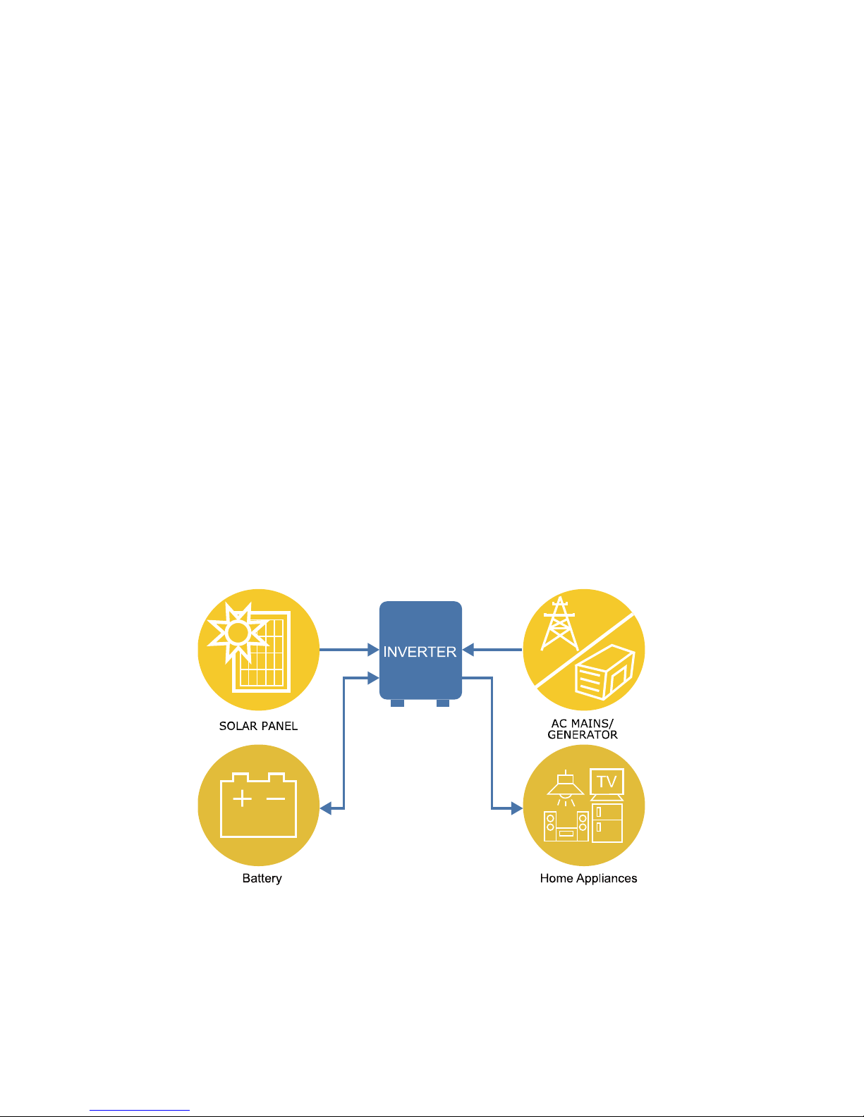
1.3 Basic System Architecture
A typical application diagram for home and office applications is as shown below.
The inverter supports the following power sources as input:
• Generator or AC utility
• PV modules(optional)
• Batteries
And the inverter is capable of supplying various loads such as fluorescent lamp,
fan, TV, refrigerator, air conditioner and so on.
Page 8
2. INSTALLATION
2.1 Unpacking and Inspection
The product package is shipped with the following items. Please call your
supplier or dealer if any items are missing.
! 1 X Inverter
! 1 X DC red cable
! 1 X DC black cable
! 1 X User’s manual
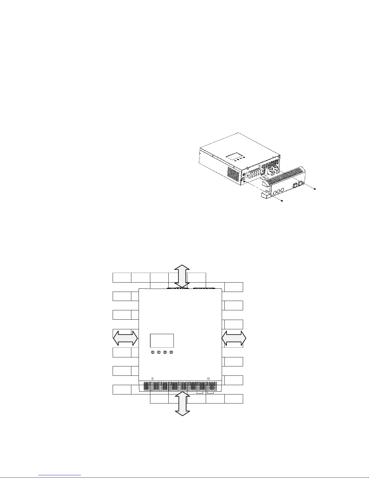
2.2 Remove bottom cover
Please take off bottom cover by removing
below 2 screws before connecting wires.
2.3 Placement
Choosing a location to install, the place should be a firm wall and a well-ventilated
room protected against rain, vapor, moisture and dust. The location should provide
adequate air flow around the Inverter with 30cm minimum clearance on all sides
for proper ventilation.
30cm
30cm
30cm
30cm
Page 9
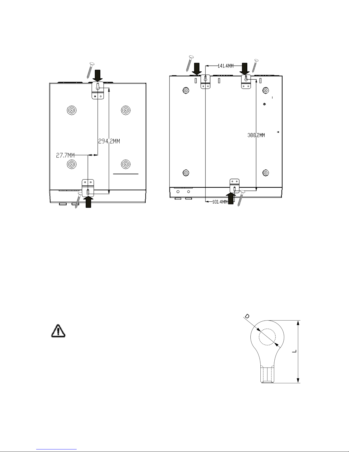
Use screws to mount the inverter to a solid surface. The recommended screw size
is M4*50~65mm.
##Screws locations of 3K model Screws locations of 5K model
2.4 Battery Connection
CAUTION: For safety operation and regulation compliance, it is requested to
install a separate DC over-current protector or disconnect device between battery
and inverter. Note that some installation requirements may not require a
disconnect device, however, an over-current protection installed is still required.
Please refer to typical amperage in below table as required fuse or breaker size.
WARNING! All wiring must be performed by a
qualified technician
WARNING! Check the polarity before connecting the battery
wires
in order not to damage the inverter.
Page 10
Recommended battery cable & cable terminal size:
Model
Number
Typical
Amperage
Battery
Capacity
Wire
Size
CABLE TERMINAL
Torque
value
Cable
mm
2
Dimensions
D(mm)
L(mm)
PowerBack
PB3000S
110A
200AH
1*4AWG
22
6.4
35
5~ 8 Nm
2*6AWG
28
6.4
35
5~ 8 Nm
PowerBack
PB5000S
100A
200AH
1*4AWG
22
8.4
35
5~ 8 Nm
2*6AWG
28
8.4
35
5~ 8 Nm
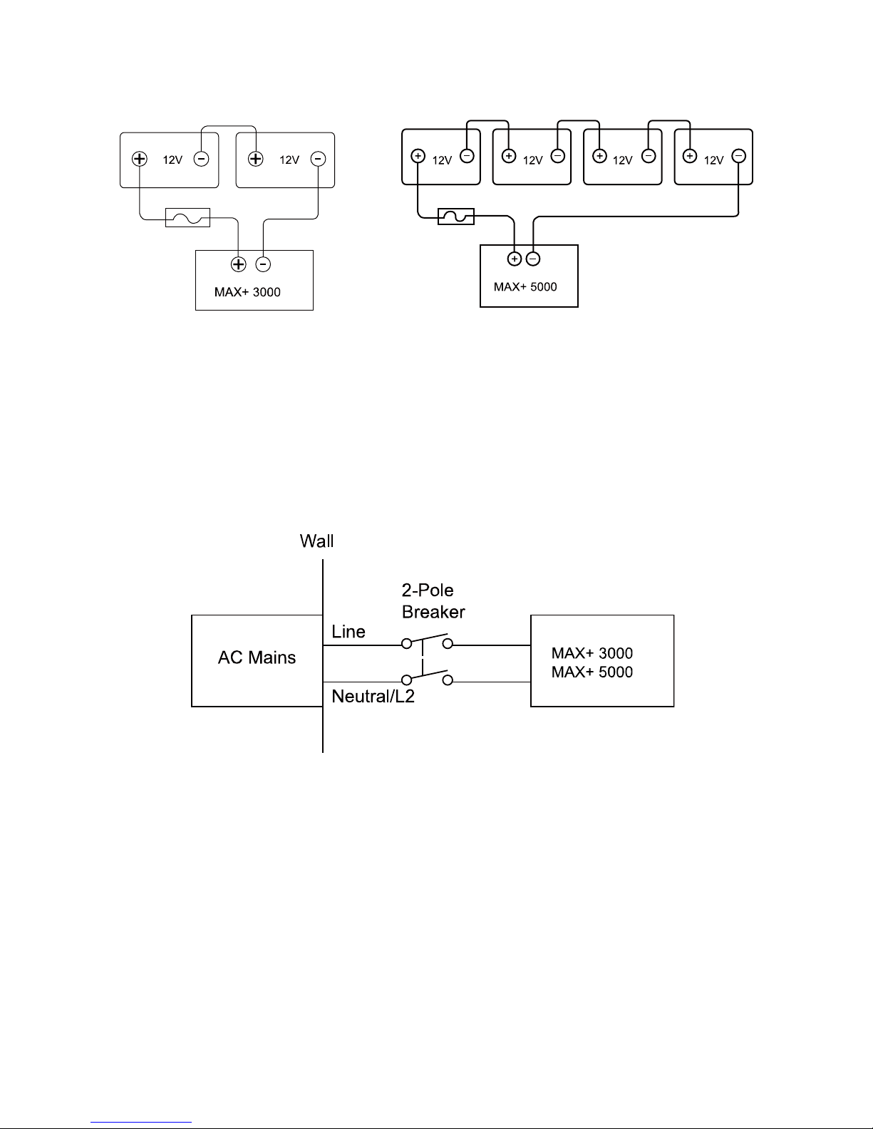
Please follow below steps to connect the batteries:
Step 1 - Install a DC Circuit Breaker for positive (+) battery cable. The rating of the
DC Circuit Breaker must be at least
140Amp for POWERBACK PB3000S,
120Amp for POWERBACK PB5000S to
guarantee safe operation without
interruption. Keep the DC Circuit
Breaker off.
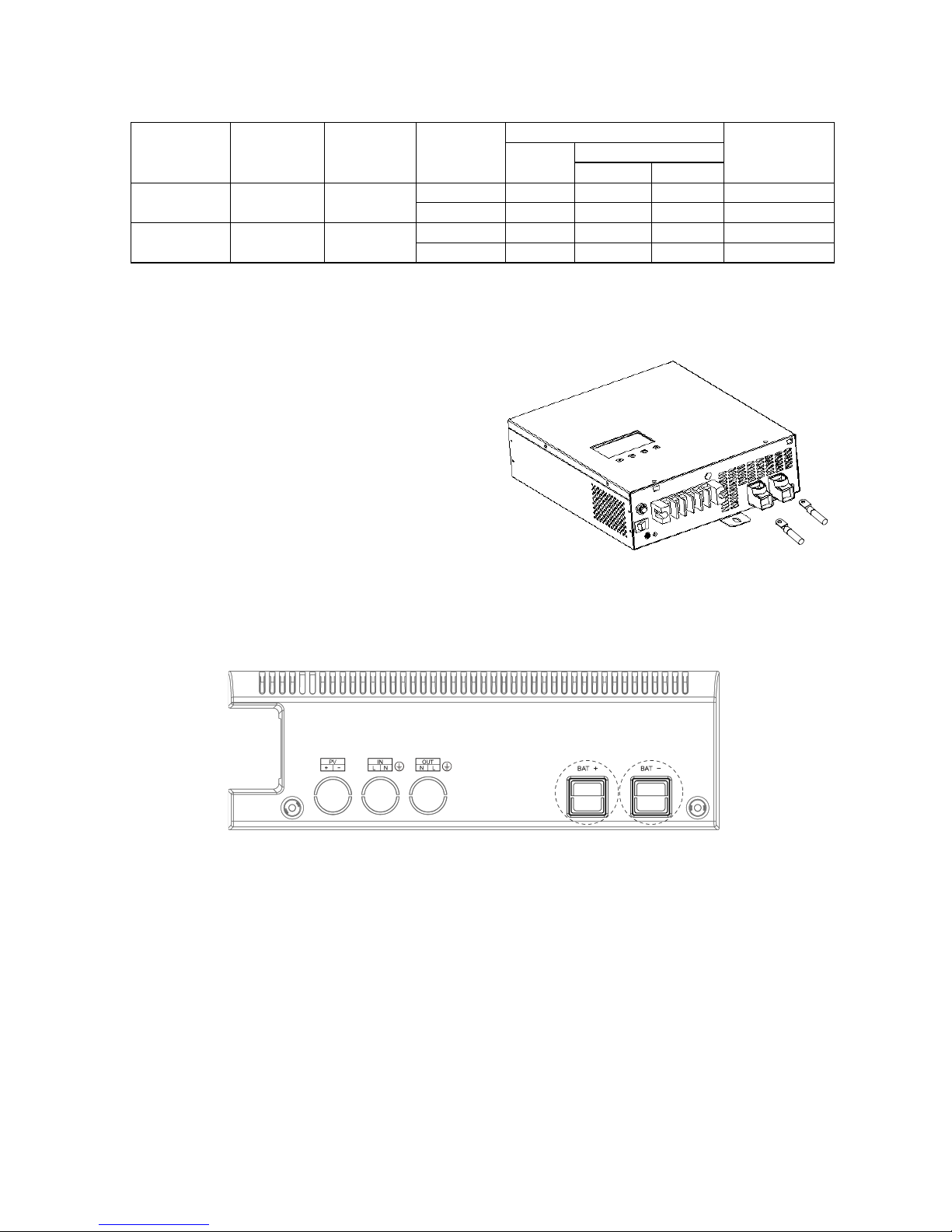
Step 2 - Connect a red cable to BAT+
terminal, and a black cable to BAT -
terminal of the inverter.
Knock off below “BAT+” and “BAT-” holes, cross red cable via “BAT+” hole and
cross black cable via “BAT-“ hole.
Step 3 - Connect the above mentioned red cable to the battery’s positive (+)
terminal and black cable to battery’s negative (-) terminal.
Step 4 - After AC input and output wires are connected, switch on the DC Circuit
Breaker.
Note: Make sure the battery voltage meets the inverter’s specification:
POWERBACK PB3000S supports 24VDC battery system; POWERBACK
PB5000S supports 48VDC battery system. And use at least 200Ah capacity
battery for POWERBACK PB3000S & POWERBACK PB5000S.
Page 11
2.5 AC Connection
CAUTION: Please install a separate AC breaker between inverter and AC input
power source. This will ensure the inverter can be securely disconnected during
maintenance and fully protected from over current of AC input. The recommended
spec of AC breaker 30A for POWERBACK PB3000S model, 40A for
POWERBACK PB5000S model. Be sure that AC source is switched off before
installing the circuit breaker.
CAUTION: Since the inverter doesn’t have an automatic protection device against
back feed current. We recommends installing an external AC contactor (see the
diagram below). A warning label shall be attached on such AC contractor to
remind the user to disconnect the inverter before accessing the circuit.
The rated voltage and current of the AC contactor shall be no less than the
inverter’s rated voltage and current, and a minimum 1.6mm space clearance shall
be reserved.
A circuit breaker shall be installed between AC mains and the inverter in order to
disconnect the AC mains when needed. Surge protection is built in. For further
protection however, we recommend installing a Sollatek DSP and Sollatek AVS.
Contact us for further information.
Page 12

Please follow the steps below to connect AC wires:
Step 1 - Disconnect the unit from the battery either by turning off the battery circuit
breaker or removing the battery cables from the battery. Note that
turning the unit off does not disconnect the batteries.
Step 2 - Remove bottom cover and knock off “PV”, “IN” & “OUT” holes.
Step 3 - Thread the AC input wires through “IN” hole of bottom cover and AC
output wires through “OUT” hole, then connect the AC input wires to input
terminal, AC output wires to output terminal & AC GND: GND
(green/yellow), Line (brown or black), and neutral (blue) wires.
Legend
B Coil Remote Switch
Q Magneto-Thermal Input Main Switch
T AC Contactor
N/L2 Neutral/L2
L/L1 L1 Line Input
External Distribution
POWERBACK PB3000S/
WARNING! All wiring must be performed by a qualified technician.
WARNING! Operation without a proper grounding connection may
result in electrical shock.
Page 13

Step 4 - Fix the bottom cover with two screws.
The recommended wire gauge and fixing torque are as below,
Model Number
AC Input
Wires Gauge
AC Output
Wires Gauge
AC GND
Wires Gauge
Torque
POWERBACK
PB3000S
12 AWG
12 AWG
12AWG
1.2~1.8 Nm
POWERBACK
PB5000S
10 AWG
10 AWG
10AWG
1.2~1.8 Nm
WARNING! The inverter is designed to be operated alone and is not designed for
parallel connection. Please DO NOT connect the inverter in parallel with any other
equipment.
2.6 PV connection
PV panel selection
PV string is a connection of PV panels whose output voltage and current vary
under different illumination. And just like battery, the PV panel can be connected in
either series or parallel as per needed. Please consult the supplier of PV panel so
that the operational voltage and current fall within the allowed range of the inverter
as set out in the specification.
Page 14

Connect PV strings
CAUTION: As the PV string generates power as long as there is light, a circuit
breaker with 60A rating shall be installed as shown below, so that PV string can be
disconnected when needed (e.g. regular maintenance).
Please follow below step to implement PV module connection:
WARNING! All wiring shall be performed by a qualified technician.
WARNING! Please do not use PV panel which requires one
terminal connected to ground (e.g. thin-film panel).
Step 1 - Disconnect the unit from the battery either by turning off the battery
breaker or removing the battery cables from the battery. Note that turning
the unit off does not disconnect the batteries.
Step 2 - Remove bottom cover & knock off “PV” hole.
Step 3 - Thread the wires through “PV” hole on bottom cover, and then connect
the PV string wires to PV input terminals. Check the polarity of wires
before connecting to terminals.
Step 4 - Fix bottom cover with two screws.
Step 5 - Turn on battery breaker or connect battery cable.
The recommended wire gauge and fixing torque are as below,
Model Number
PV Input Wire Gauge
Torque
POWERBACK PB3000S
10 AWG
1.2~1.8 Nm
POWERBACK PB5000S
10 AWG
1.2~1.8 Nm
60Amps
Page 15

3. OPERATION
After connecting batteries, AC input cables, and loads, the inverter is now ready to
work.
3.1 LCD display introduction
LCD displays the power flow and input/output readings in a visualized graphic
design which allows the user to understand the operation status easily.
Icon
Description
This icon is showed when AC input (from AC mains
or generator) presents.
If unit is on wide mode, “WIDE” will be lighted, else
“NARROW” will be lighted.
This icon is showed when PV (solar) system
presents.
The icon indicates level of remaining battery
capacity
The icon indicates battery flow way.
If unit is on CC & CV charging stages, “FAST” will
be lighted.
The icon indicates output load level. If unit work on
line mode, “BYPASS” will be lighted.
Indicate PV input voltage. PV input current, AC input
voltage, Battery voltage.
Page 16

Indicate output voltage, output frequency, load
percentage, load VA value, load watt value.
The icon indicates unit is on LCD setting mode.
The icon indicates unit is on alarm mode or fault
mode.
When unit is on LCD setting mode, it indicates
program code.
When unit is on fault mode, it indicates the fault
code which can be referred to specific fault event
(please refer to Section “Troubleshooting”).
(2) Setting Menus
After pressing and holding
button for more 2 seconds to enter setting mode,
press button for 1 second to select setting programs, then press button
to select program option, then press button to confirm the selection or
button to exit.
Program
Description
Selectable option & behavior
LCD setting display
01
AC input
voltage range
Wide (default): If selected, acceptable A
C input voltage range will be within
90-280VAC
Narrow: If selected, acceptable AC input
voltage range will be within 170-280VAC
Generator: If selected, acceptable AC
input voltage range will be within
90-280VAC
02
Output
source
priority: To
configure
load power
source
priority
Solar first(default): Solar energy provide
power to the loads as first priority.
If solar energy is not sufficient to power
all connected loads, battery energy will
supply power the load at the same time.
Utility provides power to the loads only
when any below condition happens:
-Solar energy is not available
-Battery voltage drop to either low-leve
l
warning voltage or the setting point in
program 5.
Page 17

Utility first: Utility will provide power to
the loads as first priority.
Solar and battery energy will provide
power to the load only when utility power
is not available.
SbU: Solar energy provides power to the
loads as first priority.
If solar energy is not sufficient to power
all connected loads, battery energy will
supply power the load at the same time.
Utility provides power to the loads only
when battery voltage drop to either
low-level warning voltage or the setting
point in program 5.
03
Charger
source
priority:
To configure
charger
source
priority
Solar first: Solar energy will charge
battery as first priority.
Utility will charge battery only when solar
energy is not available.
Utility first: Utility will charge battery as
first priority.
Solar energy will charge battery only
when utility power is not available.
Solar and Utility(default): Solar energy
and utility will charge battery at the same
time.
Only solar: Solar energy will be the only
charger source no matter utility is
available or not.
04
Setting
voltage point
back to
battery mode
when
selecting
"SBU priority"
or "Solar first"
in program 2.
Options in POWERBACK PB3000S
model:
Full/25.0V/25.5V/26.0V/26.5V/27.0V(def
ault)/
27.5V/28.0V.
Options in POWERBACK PB5000S
model:
Full/50V/51V/52V/53V/54V(default)/55V/
56V.
05
Setting
voltage point
back to utility
source when
selecting
"SBU priority"
or "Solar first"
in program 2.
Options in POWERBACK PB3000S
model:
21.0V/21.5V/22.0V(default)/22.5V/23.0V/
23.5V/
24.0V/24.5V.
Options in POWERBACK PB5000S
model:
42V/43V/44V(default)/45V/46V/47V/48V/
49V.
Page 18

06
Max charging
current:
To configure
total charging
current for
solar and
utility
chargers:
(Max.
charging
current=utility
charging
current +solar
charging
current)
Options in POWERBACK PB3000S
model:
20A/30A/40/50A/60A(default)/70A/
80A/90A/100A
Options in POWERBACK PB5000S
model:
20A/30A/40/50A/60A(default)/70A/
80A/90A/105A
07
Max utility
charging
current
Options in POWERBACK PB3000S
model: 0A/2A/10A/20A(default)
Options in POWERBACK PB5000S
model:
0A/2A/10A/25A (default)
08
Auto restart
when
overload
occurs
Restart disable(default):
When unit is overload, unit will release
overload alarm, then turn off output &
release fault alarm, unit won’t restart
again until end-user reduce load & press
unit’s on/off power switch.
Restart enable:
When unit is overload, overload alarm 5
seconds and turn off output for 15
seconds, then restart unit again. The
restart cycle is 5 times.
09
Low DC cut
off voltage
Auto(default):
If setting auto, low DC cut off voltage will
be relate to load percent.
20.0V for 24V model @ >=60%load
21.0V for 24V model @ <60%load
40.0V for 48V model @ >=60%load
42.0V for 48V model @ <60%load
24V model:
20.0V to 24.0V, 0.2V per step;
48V model:
40.0V to 48.0V, 0.4V per step.
Page 19

10
LCD backlight
control
Backlight auto(default):
LCD backlight will be off when no LCD
button is pressed after 1min.
Backlight all on
11
Recover
manufactory
setting
Recover enable:
Return to manufactory default setting.
Recover disable(default)
3.2 LCD display setting:
The default LCD display is:
Line mode
Battery mode
BAT+PV mode
The LCD display content will be changed in turns by pressing button. The
selectable information is switched as below order: PV input voltage, PV input
current, AC input voltage, battery voltage, output voltage, output frequency, load
percentage, load VA value, load watt value. LCD will return to default LCD display
after 1 minute, or press
button return to default LCD display immediately.
3.3 Standby Charging Mode
The battery can be charged without switching on the inverter, and such operation
is called Standby Charging Mode. When AC input cable and battery is connected,
the inverter will enter into Standby Charging Mode and LCD will be turned on with
the following display. But if charger priority setting is only solar, utility won’t charge
battery.
Page 20

If PV string is also connected with enough voltage, the display will be as shown
below to indicate the power flow from PV string. Except only solar setting for
charger priority.
Even if AC input is absent, PV power can still charge the battery and the display
will be as shown below.
3.4 Operation Modes (after powered on)
Press the Power ON/OFF button to power on the inverter and the inverter will
automatically enter into either of the operation mode according to the condition of
AC input and PV input as shown in the table below
Page 21

LINE MODE 1
AC input is present and PV input is absent. Load is supplied by AC input power
directly.
LINE MODE 2
Both AC input and PV input are present. Load is supplied by either AC input or PV
input depending on the priority switch’s setting.
Output source priority setting:
In LINE MODE 2, if priority setting is Solar first or SBU, when PV power is strong
enough to support load, the AC input will not be consumed even though it is
Page 22

present. This is deemed an energy-saving operation.
BACKUP MODE 1
Both AC input and PV input are absent. The backup power to load comes only from
battery. The backup time is determined by the capacity of battery.
BACKUP MODE 2
AC input is absent and PV power is present, if PV power is not enough to support
loads completely. The insufficient power is covered by battery.
The larger the PV power, the less consumption from battery and therefore the
longer backup time.
BACKUP MODE 3
AC input is absent and PV power is present, if PV power is strong enough, it will to not
only support the load but also charge the battery.
Page 23

As long as the PV generates power, the load can be powered continuously without
consuming power from battery.
3.5 Fault Mode
If unit is on fault mode, LCD will show the fault code which can be referred to
specific fault event (please refer to Section “Troubleshooting”).
4. SPECIFICATION
MODEL
POWERBACK
PB3000S
POWERBACK
PB5000S
CAPACITY
2.4KW/3000VA
4.2KW/5000VA
INPUT
Input Voltage Waveform
Pure sine wave (utility or generator)
Nominal Input Voltage
230Vac
Input voltage range
170Vac-280Vac(Normal);
90Vac-280Vac(Generator/Wide)
Max AC Input Voltage
300Vac RMS
Nominal Input Frequency
50Hz / 60Hz (Auto detection)
OUTPUT
Wave from
Pure sine wave (Inverter mode)
Voltage Regulation
(Inverter Mode)
±10% RMS
Output Frequency
50Hz / 60Hz ± 1Hz
Nominal Efficiency
90% (@Inverter mode with normal DC Input; >60% R load);
95% (@Line mode with Rated R load, battery full charged)
Capable of starting electric
motor
1.5HP
2.5HP
Power Factor
0.8
0.84
Over-Load Protection
Tripped off after 5s@≥150% load
Tripped off after 10s@110%~150% load
Transfer Time
(AC to DC)
Normal range : 10ms (typical) 15ms (max)
Generator/wide range: 20ms (typical) 40ms (max)
Power Limitation
POWERBACK PB3000S @ Line mode:
Page 24

AC I/P V
O/P Power
3KVA/2.4KW
90V 180V
280V
POWERBACK PB5000S@ Line mode:
BATTERY
Battery Voltage
24.0Vdc ± 0.6Vdc
48.0Vdc± 1.2Vdc
Battery low alarm voltage
21.0Vdc ± 0.6Vdc (default)
42.0Vdc± 1.2Vdc(default)
Battery low shut-down
voltage
Default:
20.0Vdc ± 0.6Vdc@
load>60%
21.0Vdc± 0.6Vdc@
load<60%
Default:
40.0Vdc ± 1.2Vdc@
load>60%
42.0Vdc± 1.2Vdc@
load<60%
Battery capacity(suggestion)
>=200Ah
AC CHARGER
Charger Current
0A/2A/10A/20A selectable
0A/2A/10A/25A selectable
Boost charger voltage (bat.
Type)
28.4Vdc
56.8Vdc
Floating charger voltage (bat.
Type)
27.4Vdc
54.8Vdc
Over charger Voltage
30.0Vdc
60.0Vdc
SOLAR CHARGER
MODULE
Max. PV Module Charger
current
80A
80A
Max PV panel array
power(base on 250W/8A PV
panel)
2000W
3750W
Max PV mode power rating
to support load
1600W
3200W
MAX. PV Input Current
50A
50A
System DC Voltage
24.0Vdc
48.0Vdc
Page 25

MPPT operating voltage
range
30~80Vdc
60~150Vdc
MPPT optimal work voltage
range
35~70Vdc
70~120Vdc
Max. PV Array Open Circuit
Voltage
80Vdc
150V
AUDIBLE ALARM
Low Battery at Inverter Mode
Beeps 1 time every 2s
Overload
110%~150%load: beep 10 times every 0.5s;
>150% load: beep 5times every 0.5s then fault.
Fault
Beeps continuously
PHYSICAL
Dimension(D*W*H)mm
342*268.2*94.4mm
436.00*394.4*118.3
Net weight
5.7KG
10.3kg
General Specification
Safety Certification
CE
Operating Environment
0°C to 50°C; 5% to 95% non-condensing
Altitude, operational
Elevation: 0~1500 Meters
Storage temperature
-15°C ~ 60°C
Troubleshooting
Problem
Possible Causes
Remedy
No LCD display
1. Battery weak
1. Re-charge battery
2. Battery defective (can't be
charged)
2. Battery replacement
3. Power switch is not
pressed
3. Press and hold power switch
4. Battery polarity reversed,
can’t start up the unit
4. Contact dealer or supplier for service
Mains normal
but works in
inverter mode
1. AC Input is missing
1. Check AC input connection
2. Input protector tripped off
2. Reset the input protector
PV input
normal but
works in
inverter mode
1.PV weak
1.Check PV power or reduce loading
2.PV input is missing
2.Check PV input connection
Page 26

Alarm buzzer
beeps
continuously
1. Overload (fault code: F2)
1. Reduce loading so the loads’ capacity
is no larger than the upper limit
2. Output short-circuited
(fault code: F3)
2. Check wiring or remove abnormal load
3. Inverter over-temperature
(fault code: F5)
3. Check the ventilation at installed
location and make sure the air vent of
inverter is clear
4. Over charging (fault code:
F1)
4. Restart the unit, If the fault persists,
contact dealer or supplier for service.
5. Fan error (fault code: F4)
5. Check if the fan is blocked by
obstacle. if not, contact dealer or
supplier for service
6. DC voltage is under low
DC shut-down point (fault
code: F0)
6. Make sure mains is normal to
recharger the battery
7. Output abnormal (fault
code: F6)
7. Contact dealer or supplier for service
8. Back-EMF, only for
POWERBAC
K
PB3000S/5000model (fault
code: F7)
8. Check the AC Input and output wire
connection
9.SCC output over current
(fault code: F11)
9.Check wiring or remove abnormal load
10.SCC over temp(fault
code: F12)
10. Check the ventilation at installed
location and make sure the air vent of
inverter is clear
11.SCC Output over
voltage(fault code: F13)
11. Restart the unit. If the fault persists,
contact dealer or supplier for service
12.SCC PV input over
voltage (fault code: F14)
12.Check PV input voltage. If the voltage
is normal, contact dealer or supplier
for service
13.SCC Fan Fault (Only for
POWERBACK PB5000S)
(fault code: F15)
13. Check if the fan is blocked by
obstacle. if not, contact dealer or
supplier for service
Back up time is
shortened
1. Overload
1. Reduce the loading
2. Battery voltage is too low
2. Charge battery for 8 hours or more
3. Battery bank is too small
3. Increase battery bank capacity
Note: If the unit fails to operate properly after installation and the setup has been
re-examined thoroughly, use the troubleshooting table to determine the probable
cause and remedy. For unlisted faults, please contact your local dealer or supplier
for service assistances.
Page 27

Alarm Behavior Table
Fault
Code
Protect
Function
Active
Mode
Condition
Warning
(O/P=ON)
Fault
(O/P=OFF)
Restart
Operate
Condition
--
Low DC
Voltage
Alarm
Inv. mode
DC
voltage<Low
DC Alarm
1beep/2s
--
--
--
1
Over
Charge
Protection
Line mode
DC
Voltage>High
DC input
Shut-down
Beep
continuous
--
Manual
--
1
Over
Voltage
Protection
Standby
DC
Voltage>High
DC input
Shut-down
--
Beep
continuously
Auto
DC
Voltage<High
DC input
Shut-down
Recovery
2
Over Load
Protection
Line/
Inv. mode
110%~150%
rated load
1beep/0.5
s,and
continue
for10s
Beep
continuously
Manual
--
>150% rated
load
1beep/0.5
s,and
continue
for 5s
Beep
continuously
Manual
--
3
Output
Short
Circuit
protection
Inv. mode
Output
Voltage<20Vr
ms
--
Beep
continuously
Manual
--
4
Inverter
Fan Fault
Protection
Line/
Inv. mode
Fan Locked
Fan Defected
2beep/2s,
and
continue for
1min
Beep
continuously
Manual
--
5
Inverter
Over
Temp
Protection
Line/
Inv. mode
HEAT SINK
over temp
--
Beep
continuously
Auto
HEAT SINK
Temp≤ 55
6
Output
Abnormal
Inv. mode
(Output
Voltage
<170Vrms and
output current
under 32Arms)
or Output
Voltage
>280Vrms
--
Beep
continuously
Manual
--
7
Bus Over
Protection
Standby/
Line/
Inv. mode
Bus voltage
over/ AC
Input and
output
reconnect
--
Beep
continuously
Manual
--
11
SCC
charger
over
current
SCC
SCC charger
current over
120A
--
Beep
1time/2Seco
nd
Manual
--
Page 28

12
SCC over
temp.
SCC
SCC NTC
Temperature
over 110℃
--
Beep
1time/2Seco
nd
Manual
--
13
SCC
Output
over
voltage
SCC
SCC Output
voltage over
30V(3K)/60V(
5K)
--
Beep
1time/2Seco
nd
Manual
/
Auto
SCC Output
voltage lower
than 24V(3K)/
48V(5K)
14
SCC PV
input over
voltage
SCC
PV Input
voltage over
80V(3K)/150
V(5K)
--
Beep
1time/2Seco
nd
Manual
/
Auto
PV Input
voltage lower
than 70V(3K)/
140V(5K)
15
SCC Fan
Fault(Only
for 5K
SCC)
SCC
SCC Fan lock
--
Beep
1time/2Seco
nd
Manual
--
Note: when SCC Fault, press ENTER Key will clear this fault message.
1) Unit will shut down after alarm for 1min, when unit on both fault mode and
Switch-off mode.
2) Unit will shut down immediately without any alarm, when unit on Switch-
on
mode with low DC input.
Input voltage setting:
(1) Normal “170V~280V”for is for valuable electronic devices. If the utility is
higher or lower than this range, the unit will transfer to inverter mode
automatically.
(2) Wide “90V~280V” for is for home application. If the utility is higher or lower
than this range, the unit will transfer to inverter mode automatically.
(3) Generator, if AC input is connected to a generator, please choose “generator”
as “Input range”.
Page 29

APPENDIX A
How to Select and Configure PV Panels
The following parameters can be found in each PV panel’s specification:
• P
max
: Max output power (W)
• V
oc
: open-circuit voltage (V)
• I
sc
: short-circuit current (A)
• Vmp: max power voltage (V)
• I
mp
: max power current (A)
PV panels can be connected in series or parallel in order to obtain the desired
output voltage and current which meets the inverter’s allowed range.
When connecting PV panels in series, the max voltage and current of the string is
V
string
= V1+V2+V3+V4…
I
string
= I1=I2=I3=I4
When connecting the above PV string in parallel, the max voltage and current of
the total string is
V
total
= V
string1=V string2=V string3=V string4
…
I
total
= I
string1+Istring2+Istring3+Istring4
In either case, the total output power is P
total
= P
panel
X Number of PV panel
The guideline to select and configure PV string is
• P
total
shall be equal or slightly larger than the max. capacity of solar battery
charger (2000W for 3000VA model and 3750W for 5000VA model). Extra
capacity in PV string will not increase the charge capacity but only result in
higher installation cost.
Model
PV panels
installed
Max. PV module to support load
3000VA
2000W
1600W
5000VA
3750W
3200W
Page 30

• Total Vmp of the string shall be within the operating voltage range of solar
battery charger (35~70V for 3000VA model and 70~120V for 5000VA model
are recommended).
Model
PV Operating voltage range
PV Optimize working voltage range
3000VA
30~80Vdc
35~70Vdc
5000VA
60~150Vdc
70~120Vdc
Example 1 - How to connect 3000VA model to PV panels with the following
parameters?
• P
max
: 250W
• V
oc
: 36.6V
• I
sc
: 8.75A
• Vmp: 30.96V
• I
mp
: 8.07A
(1) The max. PV input power for 3000VA model is 2000W,
2000W / 250W = 8⇒ min. 8 PV panels shall be connected.
(2) Best Operating Voltage Range is 35~70V,
70V/30.96V = 2.26 ⇒ max. number of PV panel in series is 2.
(3) Taking (1)~(2) into consideration, the optimized configuration is 2 PV panels
in series as a string and 4 strings in parallel, as shown below.
(4) Check again the Voc and Isc of PV string,
V
oc
of string is 73.2V < 80V (Max. PV Input Voltage) ⇒ OK
I
sc
of string is 4 x 8.75A = 35A < 50A (Max. PV Input Current) ⇒ OK
Page 31

Example 2 - How to connect 5000VA model to PV panels with the following
parameters?
• P
max
: 250W
• V
oc
: 36.6V
• I
sc
: 8.75A
• Vmp: 30.96V
• I
mp
: 8.07A
(1) The max. PV input power for 5000VA model is 3750W,
3750W / 250W = 15⇒min. 15 PV panels shall be connected.
(2) Best Operating Voltage Range is 70~120V,
120V/30.96V = 3.87 ⇒ max. number of PV panel in series is 3.
(3) Taking (1)~(2) into consideration, the optimized configuration is 3 PV panels
in series as a string, and 5 strings in parallel (as shown below).
(4) Check again the Voc and Isc of PV string,
V
oc
of string is 3 x 36.6V = 109.8V < 150V (Max. PV Input Voltage) ⇒ OK
I
sc
of string is 5 x 8.75A = 43.75A < 50A (Max. PV Input Current) ⇒ OK
Page 32

APPENDIX B
HOW TO DETERMINE THE OUTPUT SOURCE PRIORITY SETTING AND
CHARGER SOURCE PRIORITY SETTING?
Please read this document carefully if you intend to manually set the priority setting
of the product. Improper setting might compromise the function and performance of
the product.
The product is designed to accept both utility and solar (PV) power as input source,
and it also provides a function allowing the user to determine the priority between
utility and solar input power. The priority is to be set via LCD and control buttons on
the front panel (please refer to user manual for more details). This document
explains how the product’s behavior will be at each setting and what should be
considered while determine the priority.
A. Output source priority setting
1. Setting Utility as output source priority
1.1 When utility is normal
The loads connected to the product are supplied by utility power only, even when
solar power presents.
1.2 When utility is down
As soon as the utility is down, the inverter enters into “Backup Mode” and checks
both solar power and battery’s status. If solar power is strong enough, it will supply
the loads. If solar power becomes weak, the loads will then be supplied by battery
until it’s too low. The longer the solar power lasts, the less consumption from the
battery and hence the longer backup time.
Advantages
Disadvantages/Risk
backup function won’t be compromised when the utility is
down.
discharging mode.
fully utilized by supporting
the loads, especially when
battery if fully charged.
2. Setting Solar as Priority
2.1 When utility is normal
As long as solar power is strong enough to support the, utility power will not be
consumed even though it’s available. If solar power is not enough, battery will firstly
come up to support the loads, and after battery is low or the setting point in program
5, utility will then take over to support the loads.
If solar is absent, utility will then take over
to support the load too.
Page 33

2.2 When utility is down
The behavior is the same as 1.2.
Advantages
Disadvantages
power.
reducing the consumption
of utility
cycles and therefore battery’s service life will be shorter.
before the battery can fully-charged by utility, the backup
function of the product might be compromised or void.
3. Setting SbU as Priority
3.1 When utility is normal
As long as solar power is strong enough to support the loads, utility power will not
be
consumed even though it’s available. If solar power is not enough, battery will firstly
come up to support the loads, and after battery is low or the setting point in program
5, utility will then take over to support the loads and charge the battery.
2.2 When utility is down
The behavior is the same as 1.2.
Advantages
Disadvantages
power is maximized.
reducing the consumption
of utility
cycles and therefore battery’s service life will be shorter.
before the battery can fully-charged by utility, the backup
function of the product might be compromised or void.
Summary
Whether setting utility as priority or setting solar or SbU as priority is subject to
purpose of installing the product. In the event the product is to be installed in areas
where the utility power is unstable and backup function is much important than
energy saving, utility shall be set as priority.
If the product is to be installed in areas with stable utility power and strong sunlight,
and energy saving is more concerned than backup function, solar power shall be
set as priority or SbU.
B. Charger source priority setting
1. Setting Utility as charger source priority
Utility first: Utility will charge battery as first priority.
Solar energy will charge battery only when utility power is not available.
2. Setting Solar as charger source priority
Solar energy will charge battery as first priority.
Utility will charge battery only when solar energy is not available.
Page 34

3. Setting only Solar as charger source priority.
Solar energy will be the only charger source no matter utility is available or not
.
4. Setting only Solar and Utility as charger source priority.
4.1 When utility is normal
Solar energy and utility will charge battery at the same time.
4.2 When utility is down
Solar energy will charge battery.
Summary
Whether setting which option as charger source priority subject to purpose of
installing the product. In the event the product is to be installed in areas where the
utility power is unstable and backup function is much important than energy saving,
Solar and Utility or Utility shall be set as charger source priority.
If the product is to be installed in areas with stable utility power and strong sunlight,
and energy saving is more concerned than backup function, solar first or only solar
shall be set as priority, and set the maximum utility charging current as small
current as possible (program 7), for example: 2A.
Page 35

Sollatek (UK) Ltd. Sollatek House, Waterside Drive, Langley, Slough SL3 6EZ UK
ISO9001: 2008 accredited company
All weights and dimensions are approximate. Specifications are subject to change
without prior notice. ©Sollatek (UK) Limited 2012. All Rights Reserved. SOLLATEK
and the SOLLATEK device are the trade marks of the Sollatek group of companies.
SOLLATEK UK LTD.
Tel: +44 (1753) 214 500
sales@sollatek.com
www.sollatek.com
PowerBack Instructions Manual Aug 2018
A/W ID: 10910516
MJA 21.08.2018
the power to protect
 Loading...