

Page 1
THE SOLLATEK DSP3P-80/120
240/415V 80KVA
ZONE DEFENDER PRO
Instruction manual
Important: This manual contains important safety instructions.
Keep this manual handy for reference.
©Sollatek (UK) Limited 1996 All Rights Reserved.
SOLLATEK and the SOLLATEK device are the trade marks of the Sollatek group of companies.
SOLLATEK (UK) LTD
UNIT 10 POYLE 14 INDUSTRIAL ESTATE, NEWLANDS DRIVE, POYLE, SLOUGH SL3 0DX, UNITED KINGDOM
Tel: International +44 1753 688300 National 01753 688300
Fax: International +44 1753 685306 National 01753 685306
E-mail: sales@sollatek.com
www.sollatek.com
TM
TM
STATUS INDICATOR
NOTE: ALL WIRES MUST BE CONNECTED AND POWER
APPLIED BEFORE THE LED WlLL ILLUMINATE.
The DSP3P ZoneDefender PRO Series of suppressors has comprehensive, solid state, continuous visual status monitoring present in each unit. The GREEN indicator light will go
out in the event the suppressor capability is exceeded or if there is an internal safety
component failure. If the light goes out, call the factory for replacement instructions.
DIAGNOSTIC INDICATION
The DSP3P Zone Defender PRO provides a patent pending diagnostic circuitry that
monitors connected power and protection status. The following is a description of
each indication.
GREEN (ON) AC POWER is present and protection is provided.
RED (OFF)
GREEN (OFF) AC POWER is present but the Zone Defender PRO needs replaced.
RED (ON) In addition, an audible alarm will sound and the remote indication will
change states.
GREEN (OFF) AC POWER or ground is missing. Verify wire connections are correct.
RED (OFF) Make sure circuit breaker is engaged. Check panel for power.
Remote Status Indication
The DSP3P Zone Defender PRO provides for remote monitoring via a (normally open) or
(normally closed) circuit. The circuit is rated for 3amps at 120VAC. The common wire is
YELLOW, the normally open wire is BLUE and the normally closed wire is RED.
MAINTENANCE
At intervals not exceeding two months, check:
1. Status indication light
2. Conditions of connecting cables
NOTE: No customer serviceable parts inside. Opening unit WILL void Warranty.
Page 2
INTRODUCTION
This document explains how to install the DSP3P ZoneDefender PRO Series of AC Panel
Surge Protective Devices.
INSTALLATION INSTRUCTIONS
Mounting
The suppressor should be mounted as close to the panel and wire connections as
possible. The shortest and most direct wire connections will ensure best performance.
Use the four mounting holes located on the tabs to secure unit to a solid flat
surface. The type of hardware used to mount the DSP3P Zone Defender PRO will depend
on the mounting structure and are not included with the unit.
AC Power Connections
Proper wiring techniques associated with the National Electrical Codes should be
followed. The use of a 30AMP minimum circuit breaker is recommended in the event
the connection wires short or the Zone Defender PRO needs servicing.
The ¾” nipple on the DSP3P Zone Defender PRO can be inserted directly into an existing
panel knockout to ease the wire connections between the panel and the DSP3P Zone
Defender PRO. If the mounting location prevents this type of installation proper
conduit fittings should be used in order to protect the connecting wires.
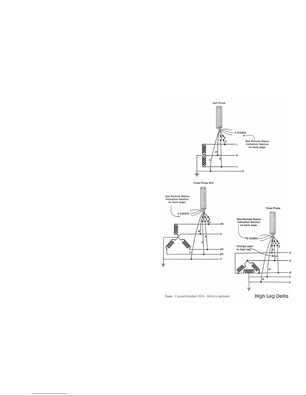
When making the connections, cut each conductor as short as possible. Avoid large
loops and sharp bends in the wire. Bind all connecting wires tightly together
throughout the wire run from the DSP3P Defender PRO to the panel. Connect the
BLACK wires to the phase conductors, connect the WHITE wire to the neutral bus
and connect the GREEN wire to the ground bus.
INCORRECT INSTALLATION WILL IMPAIR THE EFFECTIVENESS OF AC PANEL SURGE
PROTECTORS.
Particularly important is the length and routing of the
connecting leads.
CONNECTION
DIAGRAMS
 Loading...