

Sollatek AVR3x20-22, AVR3x250-22, AVR3x150-22, AVR3x200-22, AVR3x400-22 Instruction Manual
...
The Sollatek three phase
Automatic voltage regulator (AVR)
Régulateur de tension automatique triphasé (RTA)
Instruction Manual
Issue: January 2016
Édition : Janvier 2016
Important: This manual contains important safety instructions.
Keep this manual handy for reference.
Notice importante : ce manuel renferme des instructions de sécurité importantes.
Garder cette publication en lieu accessible afin d’en faciliter la consultation rapide
www.sollatek.com
the power to protect
the power to protect

Page 2 THREE PHASE AUTOMATIC VOLTAGE REGULATOR Issue: Jan 2016
Table of contents
SECTION PAGE
1. Unpacking and Inspection 3
2. Installation * 3
2.1 Safety
2.2 Positioning
2.3 Ventilation
2.4 Cables and Terminations
2.5 Circuit Breakers
2.6 Incoming connections
2.7 Outgoing connections
3. System Power-up * 6
4. Functional Description 6
4.1 General Function
4.2 AVR Function
4.3 AVS Function
4.4 -HA Function
4.5 Bypass function
4.6 Surge Arrester
5. Maintenance 9
6. Trouble Shooting 10
6.1 Safety
6.2 False Starting
6.3 Shut Down
6.4 Error modes
7. Specification/General Arrangement 11
8. Appendix 1: Bypass Installation 13
9. Appendix 2: Circuit topology 15
10. Appendix 3: On-site test procedure 23
On-site test/acceptance form
On-site repair and test procedure
11. Appendix 4: Circuit diagrams 32
* Indicates section covers more than one AVR variant
ENGLISH FRANÇAIS
Table des matières
SECTION PAGE
1. Déballage et Inspection 43
2. Installation * 43
2.1 Sécurité
2.2 Situation
2.3 Ventilation
2.4 Câbles et bornes
2.5 Rupteurs
2.6 Raccordements d’entrée
2.7 Raccordements de sortie
3. Mise sous tension du système * 46
4. Descriptif fonctionnel 46
4.1 Fonctionnement général
4.2 Fonctionnement du RTA
4.3 Fonctionnement du STA
4.4 Fonction –HA
4.5 Fonctionnement en dérivation
4.6 Protecteur de surtension
5. Entretien 49
6. Diagnostic 50
6.1 Sécurité
6.2 Faux démar rages
6.3 Mise à l’arrêt
6.4 Modes d’erreur
7. Spécication / Aménagement général 51
8. Annexe 1 : Installation en dérivation 53
9. Annexe 2 : Topologie des circuits 55
10. Annexe 3 : Procédures d’essai à pied d’œuvre 69
Formulaire pour tests / acceptation à pied d’œuvre
Procédure de réparation et d’essai à pied d’œuvre
11. Annexe 4 : Schématiques de câblage 72
* L’astérisque signale que la section concernée couvre
plus qu’une seule variante du RTA.

1. Unpacking and Inspection
It is possible that the unit will have sustained damage during transit. The following procedure
should be followed immediately upon receipt of the unit.
1.1 Crate/Packaging - Check for transit damage.
1.2 Cabinet/Casework - Check for visible signs of damage to exterior panels, doors and fittings. If cracks,
scratches or dents are visible there is a chance of internal damage. Particular attention should be paid to the
terminal panel.
1.3 Internal components - Unlock the door using the key provided. Inspect for damage to the
transformers, PCBs and other components. All mountings should be tight and there should be no sign
of movement of the transformers.
1.4 Internal wiring - All wiring connections should be checked to ensure that transit vibration has not
loosened screw terminals.
If inspection reveals problems in the above or other areas, the carrier should be notified as
soon as possible in writing.
2. Installation (Standard Version)
2.1 Safety - Under no circumstances should any work be carried out on the unit unless the supply is
isolated.
2.2 Positioning - The unit should be sited indoors on a firm, level, dry surface, away from sources of heat, dust,
vibration or moisture. A position allowing access on all four sides to permit preventative maintenance would be
advantageous.
2.3 Ventilation - The unit should be positioned such that a free flow of air is available. It is especially
important to ensure that cooling fan outlets are free from obstruction. A free space of at least 300mm should be
left in all directions around the AVR.
2.4 Cable and terminals - Before any connections can be made the incoming and outgoing cable sizes have
to be selected and, on 200A units and above, the appropriate ring terminals fitted. (See Table 2.4.1). Cable size may
be selected using values of current given in table 2.4.1 bearing in mind the usual limiting factors such as volt drop,
heating, etc. The appropriate breaker sizes are also given. Note that the input and output currents can differ
by 40%. This means that a larger cable size may have to be employed on the input than the output.
THREE PHASE AUTOMATIC VOLTAGE REGULATOR Issue: Jan 2016 Page 3
Output kVA (415V) kVA Input A Input Output Ring
Amps/ph (240V) (Max) MCCB MCCB Size mm
10 7.2 4.2 14 16 10 8
20 14 8.1 28 32 20 8
30 21 12 41 50 32 8
50 36 21 69 80 50 8
75 54 31 103 100 80 8
100 72 42 138 160 100 8
150 108 62 207 200 160 8
200 144 83 275 320 200 16
300 216 125 413 400 320 16
400 288 166 550 630 400 16
500 360 208 690 800 630 16
600 431 249 830 1000 630 16
Table 2.4.1
ENGLISH
Page 4 THREE PHASE AUTOMATIC VOLTAGE REGULATOR Issue: Jan 2016
2.5 Circuit breakers - The recommended input and output breaker ratings are given in
table 2.4.1. Values not shown may be interpolated. Due to the fact that breaker ratings jump
in large steps it is strongly recommended that adjustable trip level MCCBs are used. In this
way a high degree of protection may be achieved. The input MCCB should be of a type
suited for use with inductive loads (with a high initial surge current). The output breaker
should be chosen to suit the nature of the load.
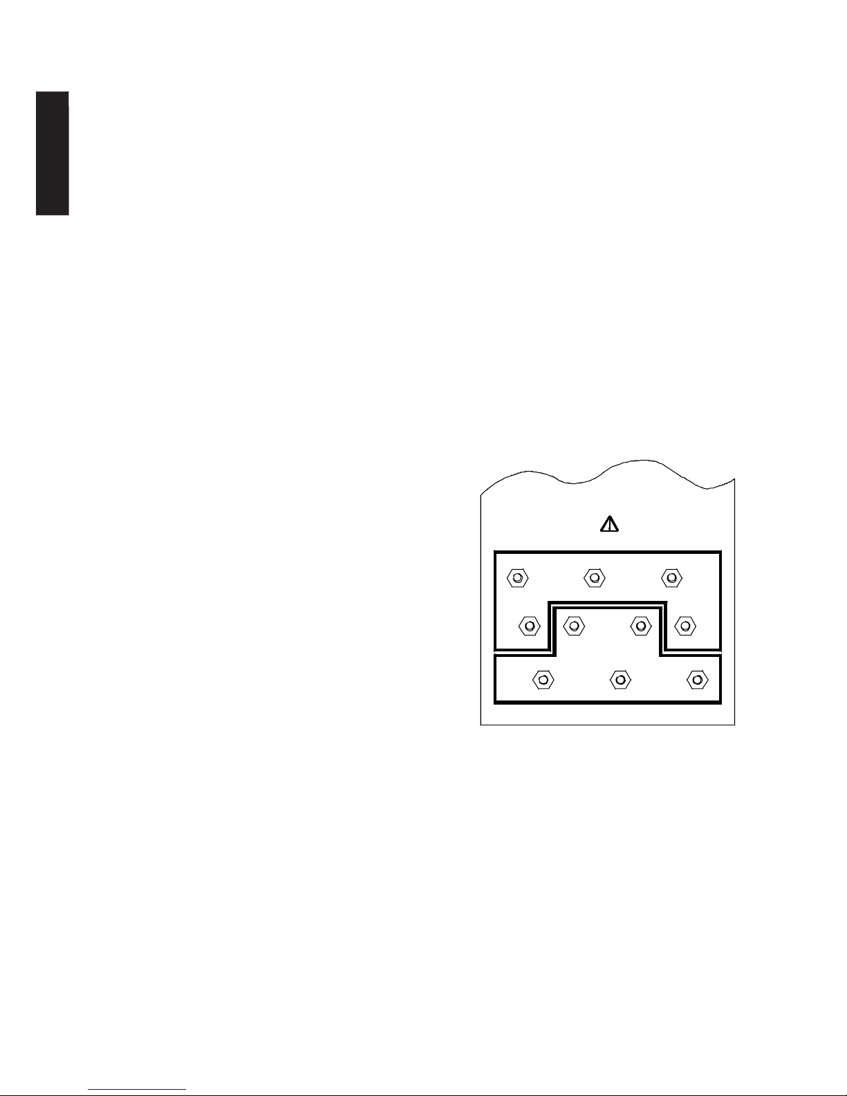
2.6 Incoming connections - The three incoming lines should be connected to the
terminals marked R1 S2 T3 on the terminal panel in the section marked INCOMING
MAINS. The incoming neutral is connected to the N terminal and the system earth is
connected to the E terminal. N.B. The AVR must be supplied with an incoming neutral
which should be fully rated. Care should be taken to ensure that all terminals are securely
tightened. See diagram 2.6.1
2.7 Outgoing connections - The three outgoing lines should be connected to the
terminals marked R1 S2 T3 on the terminal panel in the section marked OUTGOING
MAINS. The outgoing neutral should be connected to the N terminal and the load earth to
the E terminal. N.B. All neutrals should be fully rated. Care should be taken to ensure
that all terminals are securely tightened. See diagram 2.6.1 Ensure phase rotation continuity
from input to output.
INCOMING MAINS
R1 = Phase 1 in
S2 = Phase 2 in
T3 = Phase 3 in
N = Fully rated neutral in
E = Supply earth
OUTGOING MAINS
R1 = Phase 1 out
S2 = Phase 2 out
T3 = Phase 3 out
N = Fully rated neutral out
E = Load Earth
Connections should be made using ring terminals
or using the screw terminals provided.
Ensure connections are tight.
2. Installation (DS Version)
2.1 Safety - Under no circumstances should any work be carried out on the unit
unless the supply is isolated.
2.2 Positioning - The unit should be sited indoors on a firm, level, dry surface, away from sources of heat, dust,
vibration or moisture. A position allowing access on all four sides to permit preventative maintenance would be
advantageous.
2.3 Ventilation - The unit should be positioned such that a free flow of air is available. It is especially
important to ensure that cooling fan outlets are free from obstruction. A free space of at least 300mm should be
left in all directions around the AVR.
R1 S2 T3
EEN
T3
S2R1
N
SOLLATEK U.K. LTD.
R1 S2 T3 N
R1 S2 T3 N
R1 S2 T3 N
T3 N
R1 S2
Diagram 2.6.1 Terminal Arrangement
ISOLATE BEFORE HANDLING CONNECTIONS
OUTGOING MAINS
INCOMING MAINS
ENGLISH
2.4 Cable and terminals - Before any connections can be made the incoming and outgoing cable sizes have
to be selected and, on 200A units and above, the appropriate ring terminals fitted. (See Table 2.4.1). Cable size may
be selected using values of current given in table 2.4.1 bearing in mind the usual limiting factors such as volt drop,
heating, etc. Note that the input and output currents can differ by 40%. This means that a larger cable size may
have to be employed on the input than the output.
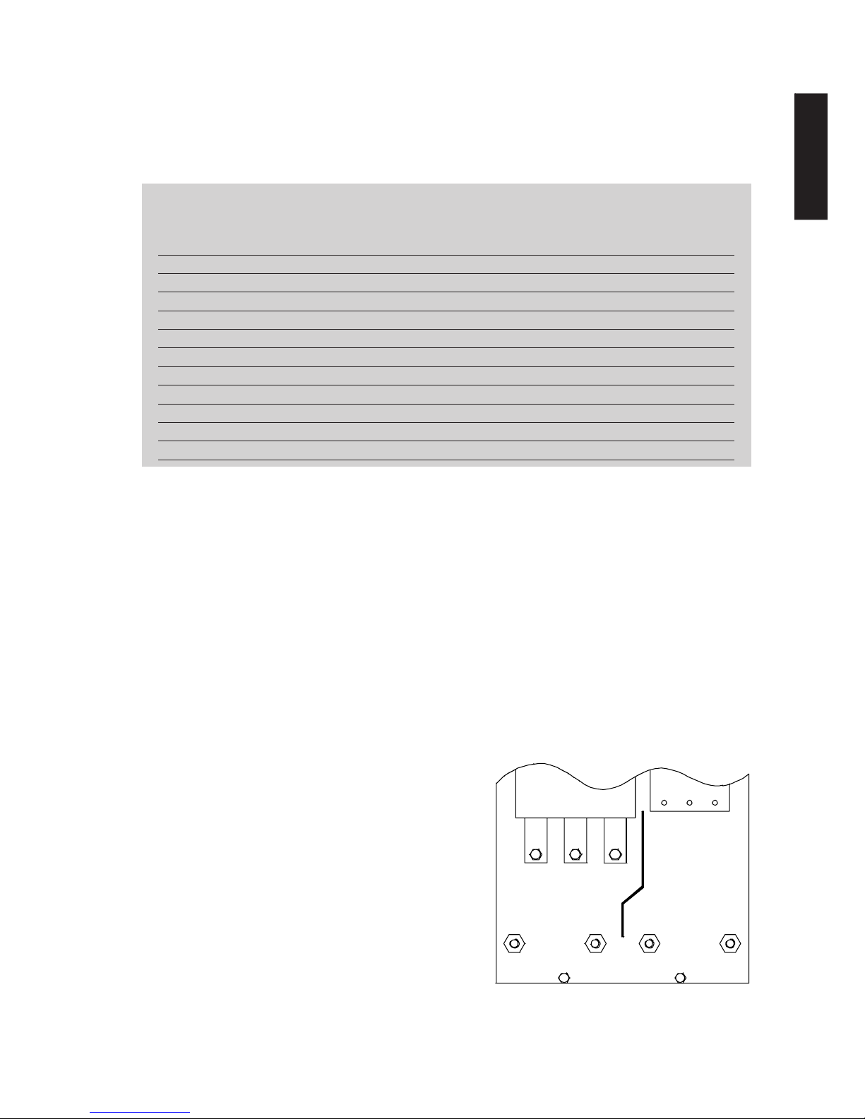
2.5 Circuit breakers – Suitably rated input and output circuit breakers are built in to the AVR. Incoming and
outgoing mains connections are made directly to the terminals of the circuit breakers (see below).
2.6 Incoming connections - The three incoming lines should be connected to the terminals marked R1 S2 T3
on the circuit breaker in the section marked INPUT C.B. The incoming neutral is connected to the N terminal and
the system earth is connected to the E terminal. N.B. The AVR must be supplied with an incoming neutral which
should be fully rated. Care should be taken to ensure that all terminals are securely tightened. See
diagram 2.6.1
2.7 Outgoing connections - The three outgoing lines should be connected to the terminals marked R1 S2
T3 on the circuit breaker in the section marked OUTPUT C.B. The outgoing neutral should be connected to the N
terminal and the load earth to the E terminal. N.B. All neutrals should be fully rated. Care should be taken to ensure
that all terminals are securely tightened. See diagram 2.6.1 Ensure phase rotation continuity from
input to output.
INPUT SIDE
R1 = Phase 1 in
S2 = Phase 2 in
T3 = Phase 3 in
N = Fully rated neutral in
E = Supply earth
OUTPUT SIDE
R1 = Phase 1 out
S2 = Phase 2 out
T3 = Phase 3 out
N = Fully rated neutral out
E = Load Earth
THREE PHASE AUTOMATIC VOLTAGE REGULATOR Issue: Jan 2016 Page 5
R1 S2 T3
EEN
T3
S2R1
N
http://www.sollatek.com
N
R1 S2
EE
Sollatek UK Ltd.
T3
N
R1 S2 T3
SOLLATEK U.K. LTD.
R1 S2 T3 N
R1 S2 T3 N
R1 S2 T3 N
T3 N
R1 S2
Output Amps/ph kVA kVA kVA
(415V) (400V) (380V)
10 7.2 6.9 6.6
20 14 13.8 13.2
30 21 20.7 19.8
50 36 34.5 33
75 54 51.7 49.5
100 72 69 66
150 108 103.5 99
200 144 138 132
300 216 207 198
400 288 276 264
500 360 345 330
600 431 414 396
Table 2.4.1
Connections should be made
using ring terminals or using
the screw terminals provided.
Ensure connections are tight.
Diagram 2.6.1 Typical Terminal Arrangement
INPUT C.B.
OUTPUT .CB.
ENGLISH

Page 6 THREE PHASE AUTOMATIC VOLTAGE REGULATOR Issue: Jan 2016
3. System power-up (Standard Version)
Before the system is powered-up for the first time the following checks should be carried
out by qualified personnel only.
A) Inspect the input and output terminations for tightness, correct wiring and phase rotation.
B) Check that the building electrical service is of sufficient capacity to supply the input current of the AVR,
remembering that this can be 40% higher than the output current to the load.
C) Check building electrical service is of correct nominal voltage and wiring configuration and that main
circuit breakers are suitable for the inductive nature of the load represented by the AVR.
D) Ensure that the load equipment is ready to be energised. Once the above conditions have been verified,
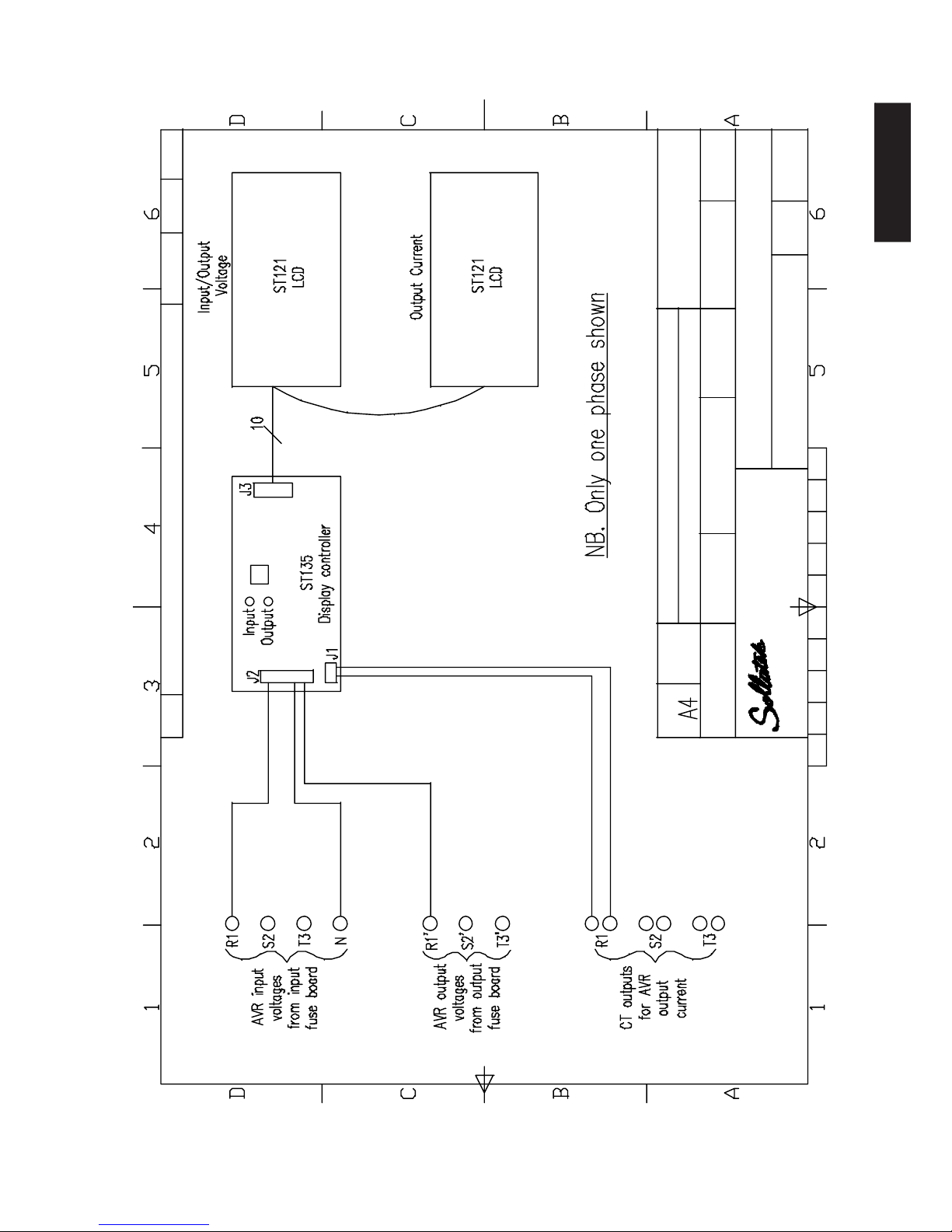
input power may be applied to the AVR. Once input power is applied the three digital voltage meters on the door
of the AVR should indicate a valid output voltage. If this is not the case switch off the power immediately and
refer to the troubleshooting section of this manual. The AVS indicators on the door (if fitted) should show ‘on’ (after
the wait time of 3 minutes).
3. System power-up (DS Version)
Before the system is powered-up for the first time the following checks should be carried out by qualified
personnel only.
A) Inspect the input and output terminations for tightness, correct wiring and phase rotation.
B) Check that the building electrical service is of sufficient capacity to supply the input current of the AVR,
remembering that this can be 40% higher than the output current to the load.
C) Check building electrical service is of correct nominal voltage and wiring configuration and that main
circuit breakers are suitable for the inductive nature of the load represented by the AVR.
D) Ensure that the load equipment is ready to be energised. Once the above conditions have been verified,
input power may be applied to the AVR. It is wise to apply power to the AVR with the input breaker in the ‘on’
position and the output breaker in the ‘off’ position.
Once input power is applied the three digital voltage meters on the door of the AVR should indicate a valid
output voltage. If this is not the case switch off the power immediately and refer to the troubleshooting section of
this manual. The AVS indicators on the door should show ‘on’ (after the wait time of 3 minutes). When it has been
verified above that the AVR is functioning correctly, the incoming power should be switched off and the output
circuit breaker set to the on position. If power is now re-applied, the load will be automatically supplied when the
3 minute delay time has elapsed.
4. Functional Description
4.1 General Function
This three phase AVR is made up from three identical single phase regulator units. Each of these monitors its own
output voltage and adjusts for variations in mains supply voltage so as to maintain an output voltage within close
limits. When the AVS function is fitted the outputs from the regulators are connected through a
contactor to the load. The contactor is controlled by a three phase Automatic Voltage Switcher PCB which
monitors the AVR outputs. This connects the load only when all the phase voltages are within acceptable limits.
There is a delay between the time when all voltages come within limits and the contactor switching on. This is so
as to allow the supply to stabilise and to avoid repeated switching of the load on and off should the mains supply
be exceptionally erratic. The state of the AVS circuit is indicated on the front panel by three large LEDs, Green for
On, Yellow for Wait and Red for Off.
4.2 AVR Function
This is based on an auto transformer with tap changing on the output. There are seven taps to each transformer
giving an accurate output voltage for a wide range of input voltage. The taps are switched by generously rated
ENGLISH

Triac banks to cope with motor start loads. Low value resistors are fitted with each Triac to ensure that high
currents are shared equally between the Triacs within each bank. This technique results in a voltage stabiliser
which has no moving parts, responds quickly to voltage fluctuations and is not as large or heavy as other AVRs
utilising different regulation techniques.
A micro-controller forms the heart of the control system. It measures the AVR output voltage and turns on the
appropriate Triac bank to select the correct tap. A potentiometer is provided for fine adjustment of the output
voltage. The micro-controller also measures the frequency of the mains supply and compensates accordingly. This
also means that the AVR will work over a frequency range of 45 - 88Hz automatically and down to as low as 30Hz
for short periods to help cope with diesel generator loading problems.
Frequency and voltage measurements are filtered by the circuit and software to remove noise and so prevent
spurious tap changes.
A watchdog function is implemented in the micro controller. This independently monitors the operation of the
micro-controller and its software. If it detects a malfunction, it will reset the micro and re-initialise the control
system.
The low voltage DC supply to the control circuit is also protected by a fuse.
Additionally, a hardware reset circuit is included which monitors the supply rail for the control circuit. If the mains
is so low that the control circuit will not function correctly, the monitor circuit will put the micro-controller into
the reset state and turn off all Triacs.
When the mains supply increases to a usable level, the monitor circuit will restart the micro and the system will
re-initialise. This ensures an orderly and controlled restart from a brownout or blackout condition. The circuit
is designed with a large hysteresis so that the unit will not attempt to turn on again until the supply voltage is
sufficient to withstand possible starting surges. This avoids the possibility of such a surge of current causing the
supply to dip sufficiently to turn the unit off again.
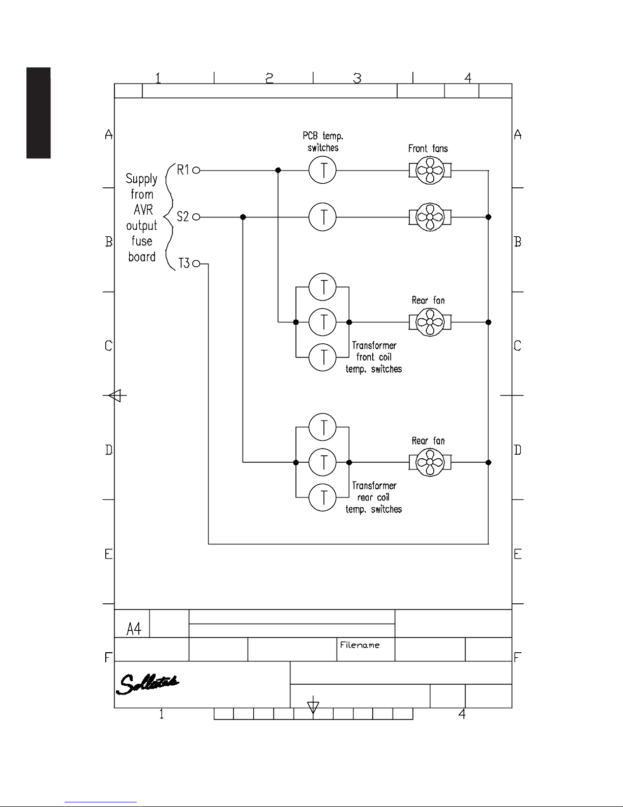
Additional protection is provided by temperature sensors fitted to each transformer. If the AVR is used at full
load and either the ambient temperature is excessively high or the ventilation grills have been obstructed, the
temperature of the transformer may increase beyond reasonable limits. In such an event, the temperature sensor
will disconnect the supply to the corresponding control board and thereby turn the output off. When the
transformer has cooled sufficiently, the sensor will restart the AVR.
When restarting after the above condition the AVR may cause equipment to begin to operate suddenly. Steps
should be taken to ensure that this does not expose persons to risk.
4.3 AVS Function [Optional - has to be ordered separately at time of purchase]
4.3.1 General Description
The Automatic Voltage Switcher (AVS) is a device for the protection of electrical equipment against fluctuations,
interruptions and other abnormalities in the electricity mains supply.
The Three Phase AVS monitors various parameters of the mains supply, and keeps it connected to the equipment
so long as all the parameters are within defined acceptable limits. This is the normal condition and it is indicated
by a Green LED (light emitting diode). If the mains voltage goes outside these limits, the AVS disconnects the
equipment from the mains and this is indicated by the Red LED (In some options, it is possible to
select indication only without disconnection's.) When the mains supply returns within the acceptable limits,
indicated by an Amber LED, the mains remain disconnect from the equipment during the wait time, set to a
nominal 1 minute by factory selected components. If during the wait time the mains again goes outside the
limits, the wait time starts from the beginning. At the end of the wait time, when the mains supply has been
continuously within the limits for its duration, normal condition returns indicated by the Green LED, and the
equipment is re-connected to the mains.
THREE PHASE AUTOMATIC VOLTAGE REGULATOR Issue: Jan 2016 Page 7
ENGLISH

Page 8 THREE PHASE AUTOMATIC VOLTAGE REGULATOR Issue: Jan 2016
The parameters monitored by the Three Phase AVS are:
a) Value of the Mains Voltage
The normal condition is when the values of the mains voltage of all the phases are within certain preset limits
referred to as the "window". The AVS detects when the voltage of any one or more phases goes outside the
window, either over- or undervoltage.
b) Phase Relationship (timing)
The AVS monitors the phase relationship between the three phases of the supply. The normal condition is when
the phase difference between the three phases is 120 degrees, corresponding to T/3 where T is the period of one
cycle.
c) Phase Rotation [optional]
The AVS can detect a phase rotation error of the three phase mains supply. Detection of parameters c) and d)
above is not standard, but are obtained by an optional plug-in board. On this board, it is possible to select by a
d.i.l. switch whether abnormality is indicated only, or it causes disconnection also.
4.3.2 Principle of Operation
The frequency and phase rotation detection circuits are explained in a separate section. The detailed operation of
the AVS in detecting the other parameters is given under CIRCUIT DESCRIPTION below. Basically, however, the AVS
compares the peak of the mains AC sinusoid of each phase with two references, one corresponding to the lower
or undervoltage limit of the window, and the other to the upper or over-voltage limit. If the mains is normal, so
that the peaks lie between the two limits and also within a time not exceeding T/3 (T is the period of one cycle),
a monostable is triggered which, after the wait time, switches the power to the equipment. If any one or more
of the peaks are below the lower limit, above the upper limit or the separation between two consecutive peaks
exceeds T/3, the AVS is reset to disconnect the equipment.
4.3.3 Checks and adjustments
a) Window Limits
P1 and P2 are adjusted to equalise the three phases, so that P1 adjusts the peak at the junction of P1 and R12, and
P2 at the junction of P2 and R20 to make them equal to the peak at the junction of R2 and R3. For measurement,
an ordinary multi-meter or digital multi-meter may be used on the AC range, since these give readings
proportional to peak.
P3 and P4 adjust the limits of the window. Start with these around the centre of their travel. Connect the normal
three phase supply to the AVS with one phase via a Variac and monitor voltage with voltmeter. Adjust Variac to
the under-voltage limit. Adjust P4 so that indication goes from Red to Amber. Adjust Variac to over-voltage limit.
Adjust P3 so that indication fluctuates between Amber and Red.
If the Variac is set so that the voltage is within the window, with Amber indicating, after the wait time (nominal 1
minute) Green will indicate and the contactor is energised.
For a complete check, three Variacs should be used, one on each phase, and the various combinations of underand over-voltage on each phase with the others tested.
b) Wait Time
The wait time is given by 0.7xR37xC6. With R37 = 820K and C6 = 100uF, the wait time is around 60 sec. to within
the tolerance of the components.
4.4 -HA Option
This option is available on all ratings of the AVR (Automatic Voltage Regulator) three phase units larger than 21kVA.
The standard Three Phase AVR provides an output which is stable to within + 4% given an input voltage variation
of + 27% from a defined nominal. Although it is likely that voltage stability of + 4% will meet most customers’
requirements, higher accuracy can be provided by incorporating a further ‘fine’ resolution stage beyond the
ENGLISH

standard AVR system.
The standard AVR incorporates a fully electronic (static) 7-tap changing system providing an output regulated to +
4%. This is fed to the -HA option which utilises a further 7 taps, again fully electronic, to achieve an output stability
of + 2.0%.
4.5 Bypass Option
4.5.1 Manual Bypass - This is used to take the AVR out of circuit, bypassing the supply straight to the load. A
fully rated, in line, mechanical switch is used to achieve this, as opposed to a relay or electronically based system.
This ensures that the supply to the AVR cannot be re-connected unintentionally by component failure or supply
disruptions. This is particularly important if the bypass is used to enable maintenance to be carried out.
4.5.2 Automatic Bypass - This facility operates to bypass the supply directly to the load in the event of a problem
associated with the AVR. If the temperature sensors built into the transformers detect that overheating is taking
place due to overloading, poor ventilation or high ambient, the bypass operates. Similarly, if the microprocessor
detects that a problem has occurred within the AVR itself, the supply is bypassed to the load.
4.6 Surge Arrester
4.6.1 Function - The unit is designed to prevent high voltage spikes and surges from causing damage either to
the AVR or to equipment down the line from the AVR. These spikes are commonly caused by lightning, sub-station
load switching or heavy motor load switching.
4.6.2 Operation - The unit is connected in parallel with the supply incoming to the AVR, forming a spur. If built in
to the AVR it will be situated above the connection terminals at the rear. Two indicators per phase are provided to
give warning of reduced protection level, in order that the surge arrester may be replaced before protection is lost.
The unit incorporates multi-stage MOV protection circuits.
5 Maintenance
This is a fully solid state AVR with no moving parts and therefore requires only the minimum of maintenance. You
can expect many years of trouble-free service with the AVR completely unattended.
Isolate the incoming mains supply before carrying out any maintenance.
The only maintenance required is to clean any dust and dirt from the outside and inside of
the casework which could be restricting the free ventilation of the equipment. If there is a
build up of dust on the PCB then this should also be carefully removed with a soft brush.
It is also wise on any equipment periodically to check the security of the electrical
connections and the condition of the cabling. Again ensure the power is turned off before
starting work.
If the AVR is damaged for any reason, or you suspect a fault, contact your nearest Sollatek
agent or Sollatek (UK) Ltd Head office for advice.
Sollatek UK Limited
Sollatek (UK) Ltd. Sollatek House, Waterside Drive, Langley, Slough SL3 6EZ UK
Tel: +44 (1753) 214 500
sales@sollatek.com
www.sollatek.com
THREE PHASE AUTOMATIC VOLTAGE REGULATOR Issue: Jan 2016 Page 9
ENGLISH

Page 10 THREE PHASE AUTOMATIC VOLTAGE REGULATOR Issue: Jan 2016
6 Trouble Shooting
6.1 Safety - Under no circumstances should any work be carried out on the unit unless the supply is
isolated.
6.2.False Starting.
If it is found that the AVR keeps trying to start but turns off immediately, this is most likely to be due to poor wiring
to the AVR or in the building. This could be:
a) Cabling is not thick enough.
b) Cabling is too long for its thickness leading to excessive volt drop.
c) Poor joints or connections.
Any such problems should be corrected, so that the supply can deliver the high currents necessary to run the
load.
6.3 Shut Down
If it is found that the unit switches off after some time even when the mains voltage is good, it may be that the
AVS is detecting some bad condition of the mains supply that is not apparent without the use of test equipment.
Alternatively, it may be that the temperature overload is operating, in which case the following points should be
checked:
a) The output current is not above that stated on the serial label at the rear of the AVR.
b) The AVR is not subject to excessive ambient temperature due to a poor location near a source of heat.
c) The ventilation grills on the side of the AVR case have not been covered or blocked.
d) That there is room for free movement of air around the outside of the AVR casework.
Common trouble shooting points:-
Problem Cause/Solution
AVR trips main breaker at switch on. 1. Check that input and output wiring is not shorted out.
2. Check that input circuit breaker is suitable for
inductive loads.
AVR shuts down after a period of 1. Check that load does not exceed rated output.
normal operation. 2. Check that ventilation ducts/fan outlets are not blocked.
3. Incoming voltage may be too low to drive AVR
electronic systems.
AVR shuts down immediately upon 1. Check terminal joints and connections
switch on. satisfactorily made.
2. Check incoming cable is of sufficient capacity.
3. Check that cable run not too long causing
excessive volt drop.
Input power is present but there is no output. 1. Check that AVS indicators (if fitted) show ‘on’
2. Check that circuit breakers (if fitted) are in the ‘on’
position.
Three phase equipment rotates Phase rotation problem. Check incoming and outgoing
backwards. mains wiring
ENGLISH

6.4 Error Modes
If the AVR has shut down it is possible to observe the LEDs on the PCBs within the unit. These can display two
different error modes.
This procedure should be carried out by qualified personnel only.
The main door to the unit may be opened whilst the supply is still connected. It is then possible to see the PCBs.
There are a number of LEDs visible down one edge of each of the three PCB groups. One of the following two
error indications may be observed.
a) The square LEDs in a group scan in a cyclical pattern starting at the top moving to the bottom repeatedly. This
indicates that a fault has occurred in the voltage measurement feedback circuit. Contact your nearest Sollatek
agent or Sollatek (UK) for advice.
b) The green and red undervoltage LEDs in the same group flash. This indicates that an AVR system fault has
occurred. Again, contact Sollatek for advice.
These indications may be observed on any or all of the three PCB groups.
7. Specifications
Model : Three Phase Automatic Voltage Regulator
Input voltage : 230/400V +22% -30% (Other voltages available)
Output voltage : 230/400V +/- 4% (+/- 2.0% with HA Option)
Correction time : within 15 m sec
Frequency range : 45Hz to 88Hz
Voltage protection : Automatic under voltage protection
THD : < 0.25%
Max. amb. Temp. : 40 C
Acoustic Noise : < 45 dB
Expected Service Life : > 25 years
Technology : All solid state (static) switching
Bypass modes : Manual bypass for maintenance. Automatic bypass on
(Optional) AVR fault and overload.
Restart modes : Supply to output is automatically disconnected when
(optional AVS) supply outside preset limits and re-connected when
voltage becomes good. Built-in 3 minute delay.
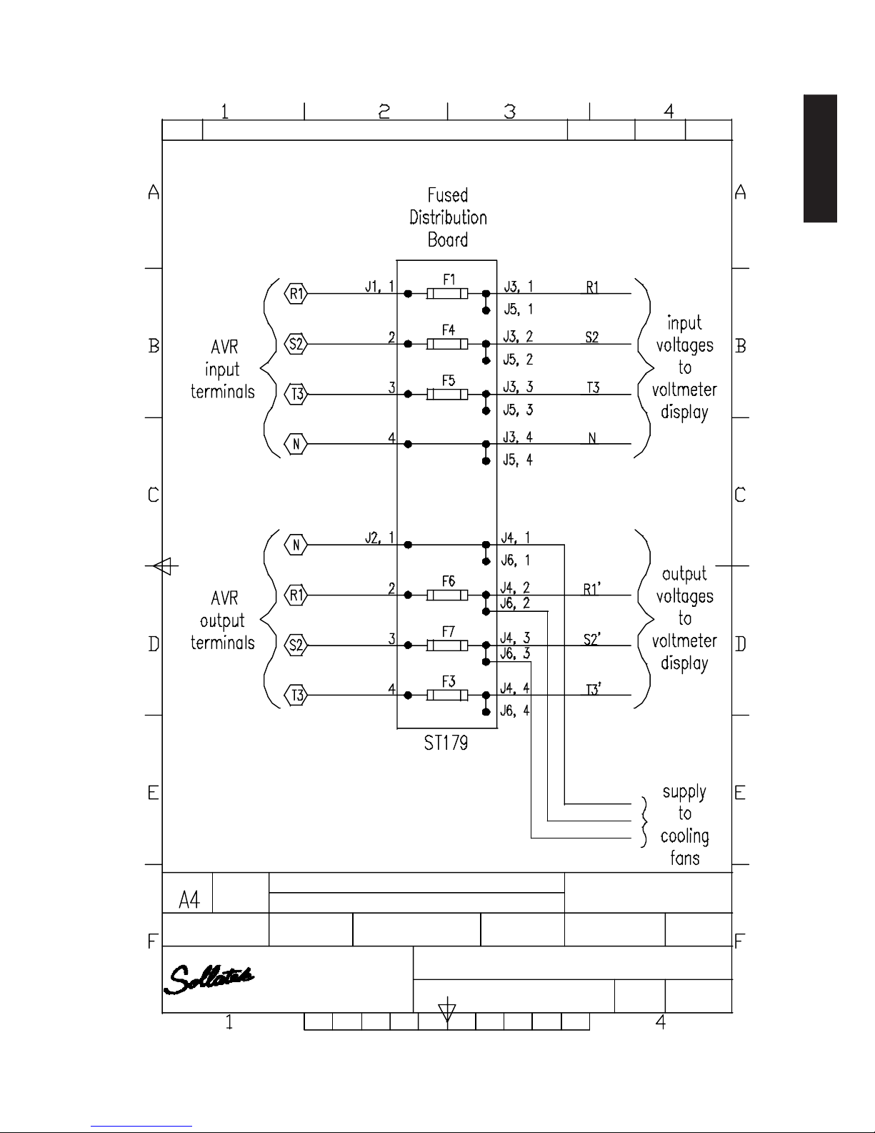
Filtering (Optional) : Input and output noise and spike filtered
Standards : Manufactured to comply with :-
EN60065
EN60555
BSEN50081
BSEN50082
THREE PHASE AUTOMATIC VOLTAGE REGULATOR Issue: Jan 2016 Page 11
ENGLISH
Page 12 THREE PHASE AUTOMATIC VOLTAGE REGULATOR Issue: Jan 2016
ENGLISH
Model Weight Dims (mm)
kg W x D x H
AVR3x20-22 100 450 x 635 x 850
AVR3x30-22 150 450 x 635 x 850
AVR3x50-22 210 500 x 685 x 1060
AVR3x75-22 285 600 x 735 x 1110
AVR3x100-22 400 500 x 835 x 1280
AVR3x150-22 450 500 x 835 x 1280
AVR3x200-22 575 680 x 1200 x 2070
AVR3x250-22 675 680 x 1200 x 2070
AVR3x300-22 735 680 x 1200 x 2070
AVR3x400-22 790 680 x 1200 x 2070
AVR3x700-22 1200 1360 x 1200 x 2070
AVR3x800-22 1590 1360 x 1200x 2070
AVR3x900-22 1700 1360 x1200 x 2070
AVR3x1000-22 1850 2040 x1200 x 2070
Up to 3000A per phase available
APPENDIX 1
Bypass installation procedure
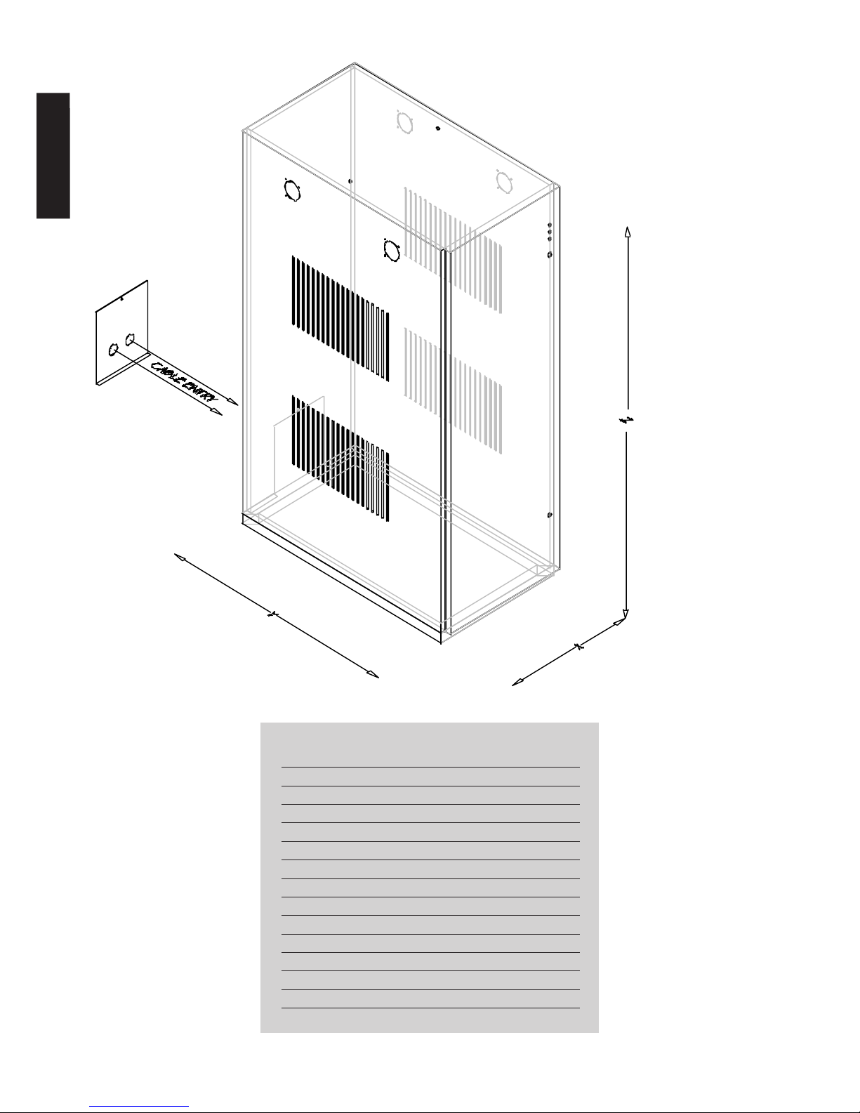
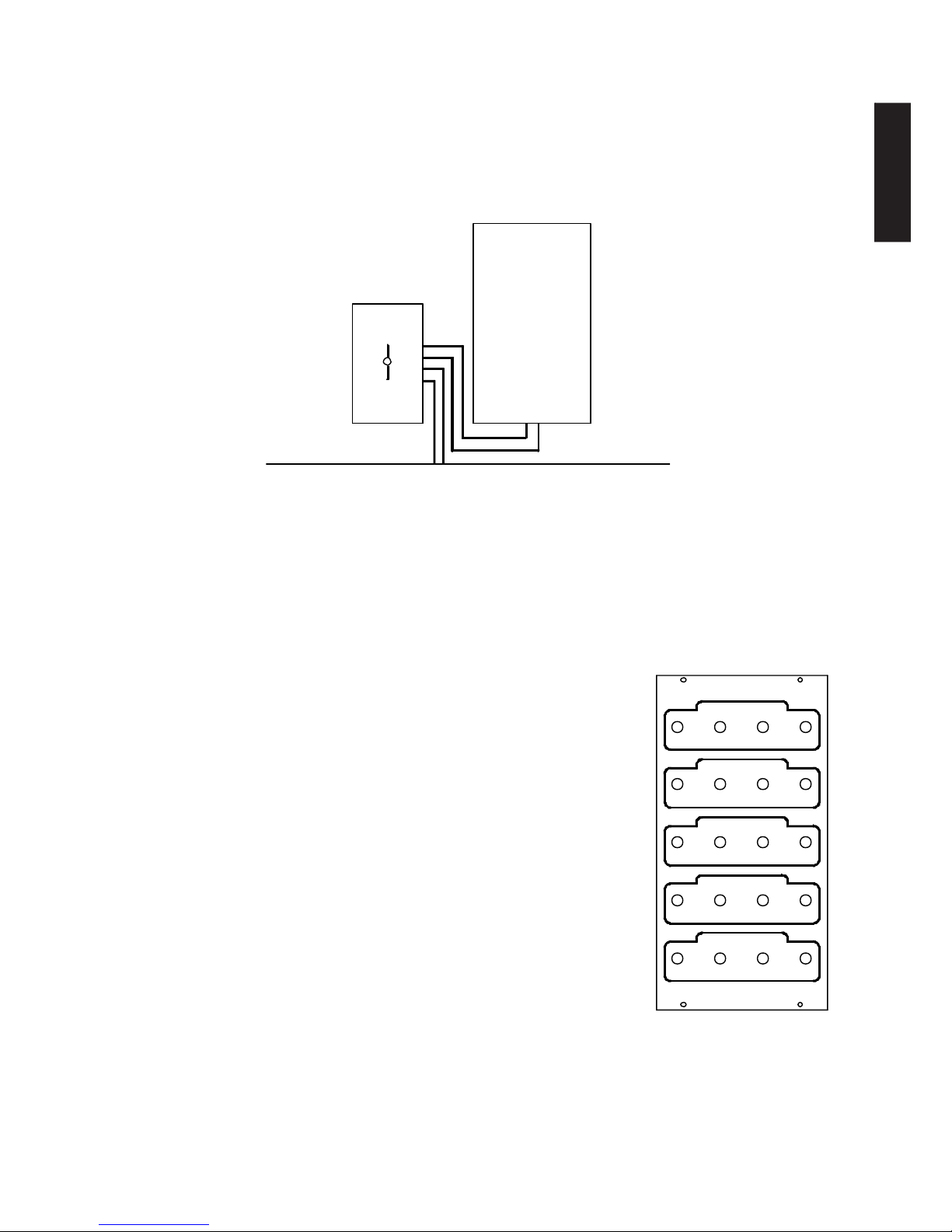
1. Positioning
The bypass should be installed directly next to the AVR to allow wiring between the two units. Both units should
be positioned as closely as possible to the incoming supply access. See AVR manual for further positioning
requirements.
Fig 1. Bypass positioned close to AVR and utility access point
2. Interconnection
In the standard bypass connection configuration, the main incoming supply and load output are connected at
the bypass. Connections are then made to and from the AVR using the terminals provided on the bypass terminal
panel. The AVR and bypass should be connected together using the cable kit provided. This kit consists of nine
identical cables two meters in length (three phases and neutral in and out plus one earth connection). The bypass
terminal panel shows connection information. See AVR manual for further information on cable
connection. NB Ensure all connections are tight.
The bypass is fitted with a terminal cover to prevent accidental contact with the
terminals. It is necessary to remove this cover and feed the cables through before
replacing it after the connections have been made.
3. Bypass operation
When the AVR is required to be in circuit, during normal operation, the operation
handle on the top of the bypass case should be in the ‘normal’ position. This takes
the incoming supply via the AVR to the load. When the AVR needs to be taken out
of circuit, for instance to perform maintenance, the operation handle should be
moved to the ‘bypass’ position. This takes the incoming mains directly to the load
and the AVR is isolated.
4. Alternative bypass connection
There is an alternative bypass/AVR connection method that may be employed if
desired. In this case, the bypass is used to select between the regulated supply
from the AVR and the incoming mains supply as the feed to the load. Connections
are as indicated on the terminal panel with the exception the terminals marked ‘TO
AVR’ are not used. (See Diagram)
N.B. This arrangement does not allow the bypass to be used to isolate the
AVR for maintenance.
THREE PHASE AUTOMATIC VOLTAGE REGULATOR Issue: Jan 2016 Page 13
EEN
T3
S2R1
http://www.sollatek.com
EE
Sollatek UK Ltd.
T3
N
R1 S2 T3
SOLLATEK U.K. LTD.
R1 S2 T3 N
R1 S2 T3 N
R1 S2 T3 N
T3 N
R1 S2
SOLLATEK U.K. LTD.
R1 S2 T3 N
R1 S2 T3 N
R1 S2 T3 N
T3 N
R1 S2
Fig 2. Bypass terminal panel
marking
AVR
BY-PASS
TERMINALS
TERMINALS
AVR INPUT AND OUTPUT CABLES
INCOMING SUPPLY AND
OUTGOING LOAD CABLES
INCOMING SUPPLY
OUTPUT TO LOAD
TO AVR
FROM AVR
EARTH
ENGLISH
Page 14 THREE PHASE AUTOMATIC VOLTAGE REGULATOR Issue: Jan 2016
Fax:
01753
685306
Tel: 01753 688300
Slough, Berks. SL3 0AX.
Blackthorne
Road,
Poyle,
Units 4/5, Trident Ind. Est.,
DWG. No.
Title:
Edition
Sheet
Scale
Date
Filename
Approved by - date
Checked
by
Designed
by
1198
nts
15/2/01
183501
1835.01
AVR & Bypass switch wiring
rgb
Quantity
Material-
Finish-
Size
Article No./Reference
Date
Revision note
RevNo
ENGLISH

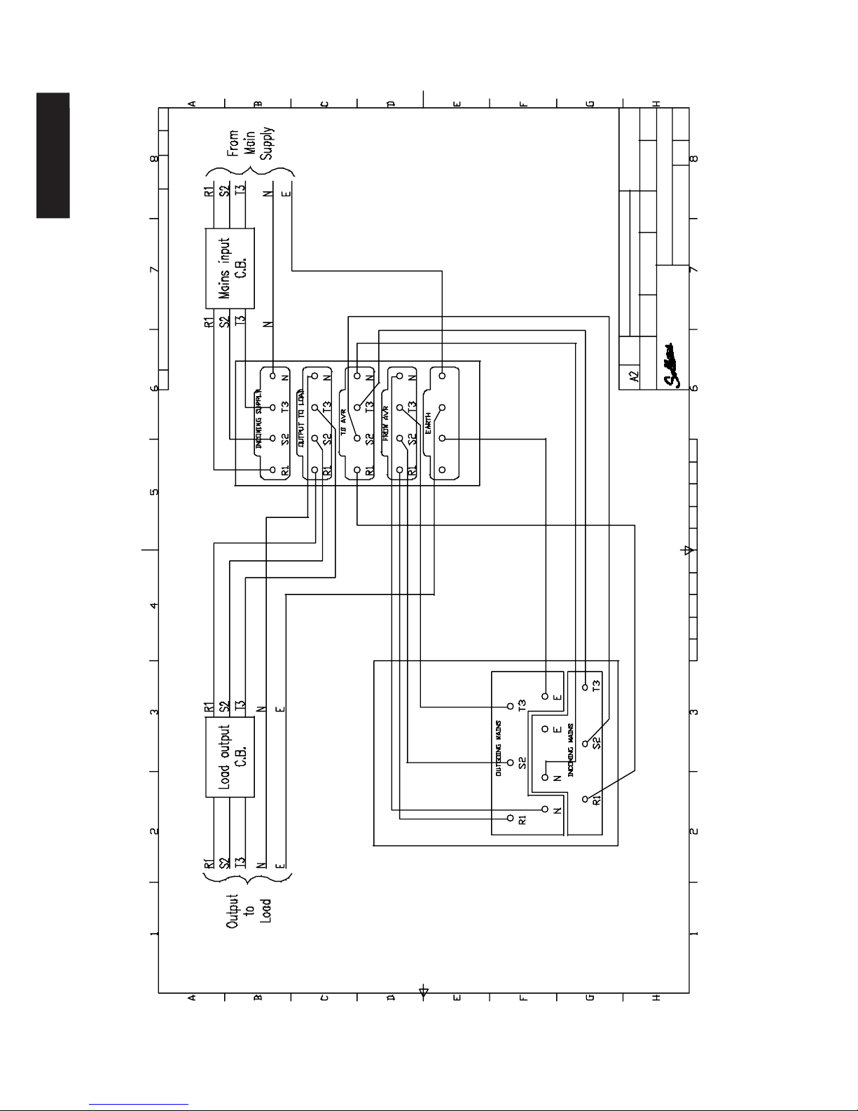
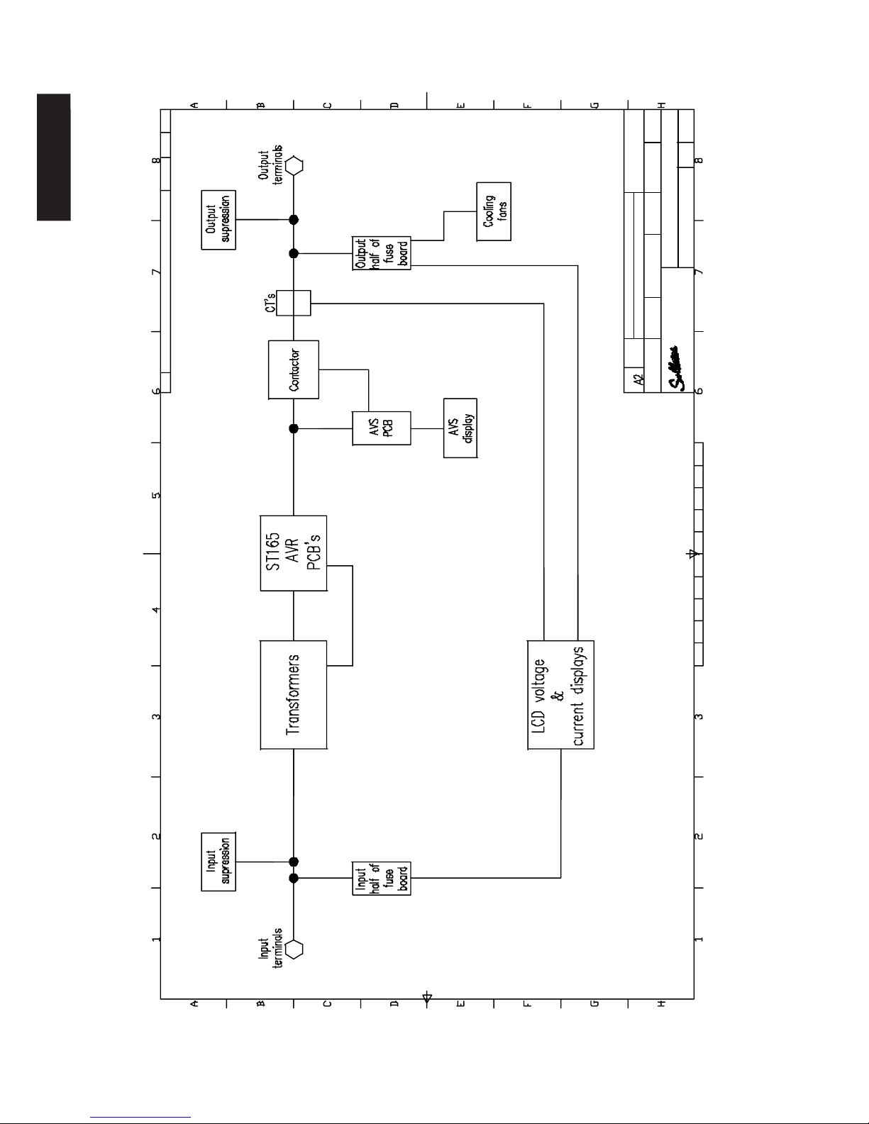
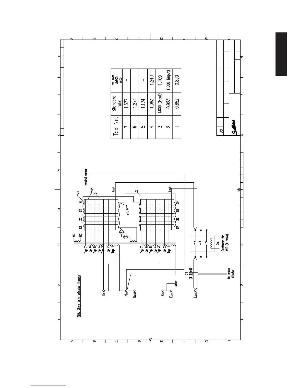
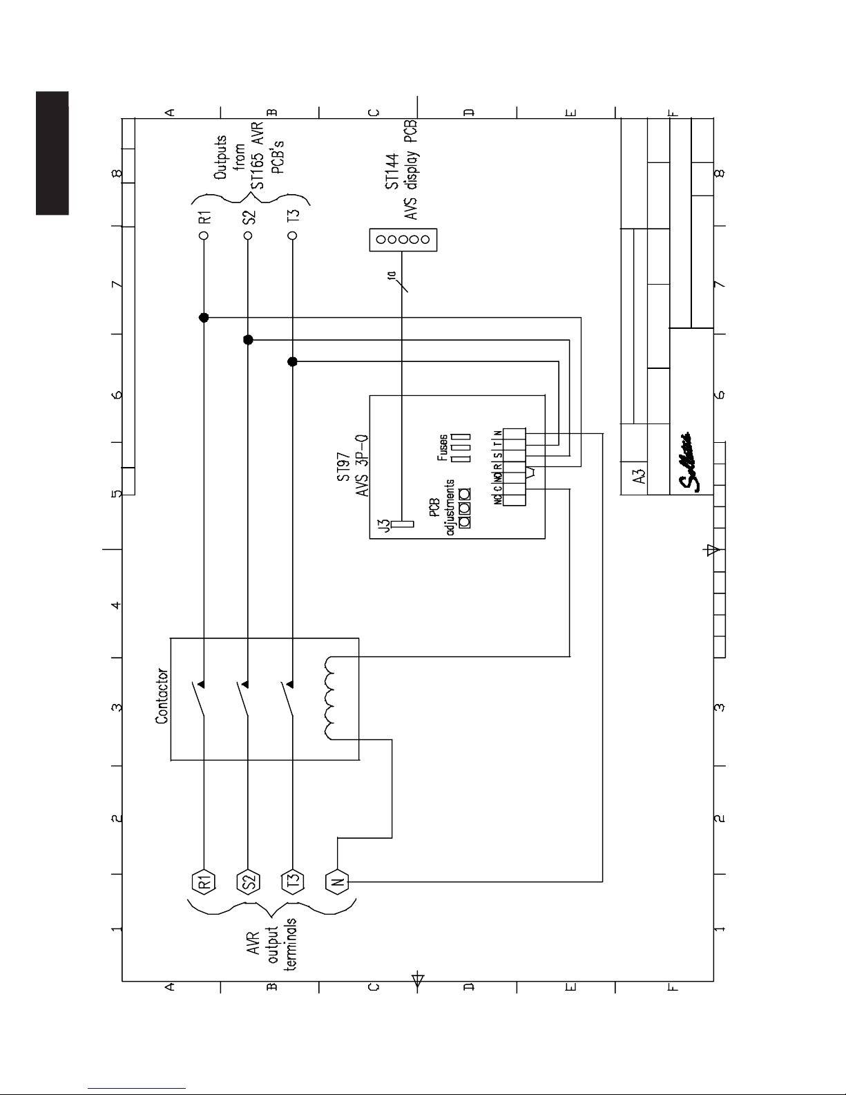
APPENDIX 2
System topology diagrams
1. Main AVR
2. Main power PCBs
3. Cooling fans
4. LCD Display
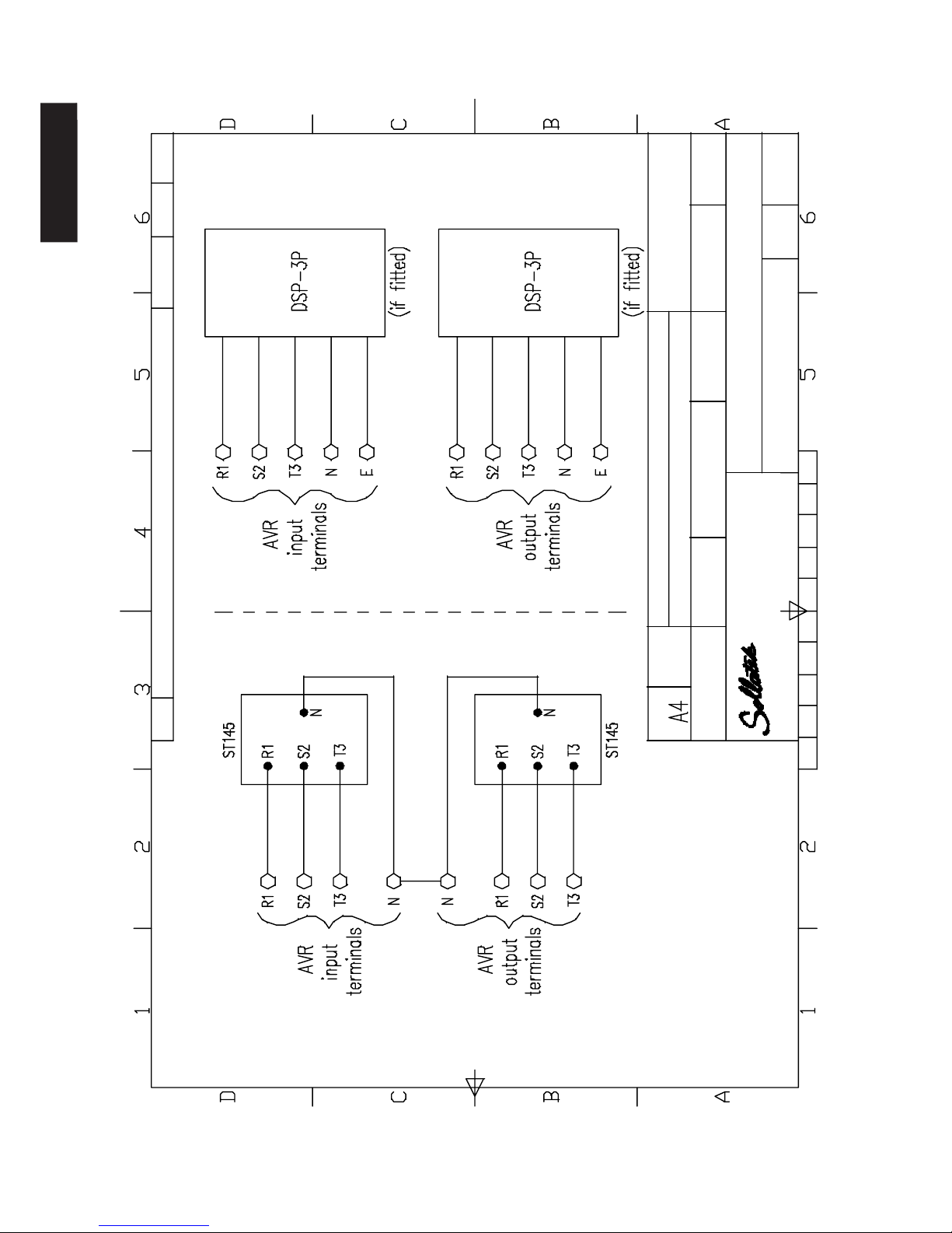
5. Distribution surge protection
6. Fuse PCB
7. Automatic Voltage Switcher
THREE PHASE AUTOMATIC VOLTAGE REGULATOR Issue: Jan 2016 Page 15
ENGLISH
Page 16 THREE PHASE AUTOMATIC VOLTAGE REGULATOR Issue: Jan 2016
Slough, Berks. SL3 0AX.
Blackthorn
e Road,
Poyle,
Units 4/5, Trident Ind. Est. ,
1211
nts
13/3/
01
184501
1845.01
AVR block
diagram
rgb
Filename
Approved by - date
Tel:
01753
688300
Fax:
01753
685306
DWG. No.
Title:
Scale
Date
Edition
Sheet
Article No./Reference
Date
Revision note
RevNo
Designed
by
Checked by
Quantity
Size
Finish
-
Material-
ENGLISH
THREE PHASE AUTOMATIC VOLTAGE REGUL ATOR Issue: Feb 2002
1217
nts
14/3/01
185101
1851.01
AVR PCB/ xfmr conn ection
rgb
Filename
Approved b y - dat e
Scale
Date
Edition
Sheet
Article No./Refe rence
Date
RevNo
Revision note
Designed by
Size
Units 4 /5, Tride nt Ind. Est.,
Blackthorne Road, Poyle,
Slough, B erks. SL3 0AX.
Checked by
Tel: 01753
688300
Fax: 01753
685306
Material-
Quantity
Finish-
Title:
DWG.
No.
THREE PHASE AUTOMATIC VOLTAGE REGULATOR Issue: Jan 2016 Page 17
ENGLISH
Page 18 THREE PHASE AUTOMATIC VOLTAGE REGULATOR Issue: Jan 2016
THREE PHASE AUTOMATIC VOLTAGE REGUL ATOR Issue: Feb 2002
DWG. No.
1216
nts14/3/01185001
1850.01
AVR cooling fans
rgb
Approved by - date
Units 4/5, Trident Ind. Est.,
Blackthorne Road, Poyle,
Slough, Berks. SL3 0AX.
Tel: 01753 688300
Fax: 01753 685306
Material-
Finish-
Checked by
Designed by
Size
Quantity
Title:
Revision noteRevNo
Edition
Article No./Reference
Date
Sheet
Scale
Date
ENGLISH
THREE PHASE AUTOMATIC VOLTAGE REGUL ATOR Issue: Feb 2002
Revision note
RevNo
Date
1215
nts
14/3/01
184901
1849.01
AVR - LCD V & I displays
rgb
Approved by - date
DWG. No.
Tel: 01753 688300
Designed by
Quantity
Size
Slough, Berks. SL3 0AX.
Units 4/5, Trident Ind. Est.,
Blackthorne Road, Poyle,
Checked by
Material-
Finish-
Title:
Fax: 01753 68530
6
Article No./Reference
Date
Filename
Scale
Edition
Sheet
THREE PHASE AUTOMATIC VOLTAGE REGULATOR Issue: Jan 2016 Page 19
ENGLISH
Page 20 THREE PHASE AUTOMATIC VOLTAGE REGULATOR Issue: Jan 2016
THREE PHASE AUTOMATIC VOLTAGE REGUL ATOR Issue: Feb 2002
Revision note
RevNo
Date
1214
nts
13/3/01
184801
1848.01
A
V
R
3
ø
s
u
p
p
r
e
s
s
o
r
P
C
B
's
rgb
Approved by - date
Slough, Berks. SL3 0AX.
Blackthorne Road, Poyle,
Units 4/5, Trident Ind. Est.,
Fax: 01753 685306
Quantity
Material-
Finish-
Designed by
Size
Checked by
Tel: 01753 688300
Edition
Article No./Reference
DWG. No.
Filename
Title:
Date
Scale
Sheet
ENGLISH
THREE PHASE AUTOMATIC VOLTAGE REGUL ATOR Issue: Feb 2002
1213
nts13/3/01184701
1847.01
AVR fuse distribution PCB's
rgb
DWG. No.
Tel: 01753 688300
Fax: 01753 685306
Slough, Berks. SL3 0AX.
Blackthorne Road, Poyle,
Units 4/5, Trident Ind. Est.,
Checked by
Material-
Finish-
Designed by
Size
Quantity
Approved by - date
Title:
RevNo Revision note
Edition
Article No./Reference
Filename Date
Sheet
Scale
Date
THREE PHASE AUTOMATIC VOLTAGE REGULATOR Issue: Jan 2016 Page 21
ENGLISH
Page 22 THREE PHASE AUTOMATIC VOLTAGE REGULATOR Issue: Jan 2016
THREE PHASE AUTOMATIC VOLTAGE REGUL ATOR Issue: Feb 2002
1212
nts
13/3/01
184601
1846.01
A
V
S
o
p
tio
n
fo
r
3
ø
A
V
R
rgb
Filename
Edition
Sheet
Date
Article No./Reference
Scale
Date
Revision note
RevNo
Units 4/5, Trident Ind. Est.,
Slough, Berks. SL3 0AX.
Blackthorne Road, Poyle,
Fax: 01753 685306
Tel: 01753 688300
Checked by
Material-
Finish-
Designed by
Size
Quantity
DWG. No.
Approved by - dat
e
Title:
ENGLISH

Final Test Procedure Document Number: QP07
Product Name: Installed Large AVR Variants: All ST165 based
Inspection Checklist
1. Check PCBs for damage, poor alignment, comb positioning and general condition.
2. Ensure that all internal nuts, bolts and fixings are secure and that nothing has come loose during installation.
3. Examine all wiring, paying particular attention to power cable terminal tightness. If Bypass is fitted, check all
power connections. Check crimp joints have not loosened.
Check all pink/grey connections are correct and that ribbon cable connectors have not been dislodged.
4. Clean all exterior panel work and check for damage.
Function Test
1. Note all results on form QF07.
2. Using a variac on input of one phase at a time, with a test lamp at the output, increase voltage until ST165
master switches on (reset LED goes off). Note input voltage. This should be in the range 140V to 170V.
3. Reduce input voltage and note voltage at which reset LED lights. This should be between 120V and 135V.
4. Increase input voltage from 160V and note output voltage at which tap down occurs on each tap. This should
be at 240V +/- 1V.
5. From 270V reduce input voltage and note output voltage at which tap up occurs on each tap. This should be
at 220V +/- 1V.
6. Set output voltage to 220V on brown tap. Input voltage should be less than 161V.
7. Set output voltage to 240V on violet tap. Input voltage should be greater than 280V.
8. Set input voltage to 230V. Compare measured input voltage to displayed input voltage. Difference should not
exceed 2%.
9. Compare measured output voltage to displayed output voltage. Difference should not exceed 2%. AVS must
be
operational for this test.
10. Compare measured output current to displayed output current. Difference should not exceed +/- 10% at
20% full load. AVS must be operational for this test.
11. Connect two phases to the input of the AVR. Connect the third phase via the variac. Adjust the variac voltage
to 230V. Time the delay before AVS switches on. This should 10 seconds +/- 5%. Ensure AVS amber LED
illuminates during wait.
12. Increase variac voltage until AVS cuts out. Note AVS input voltage. This should be 260V +/- 3 V. Ensure Red
overvoltage LED is illuminated.
13. Reduce input voltage to 230V. Ensure AVS amber LED is illuminated. Once AVS has re-connected reduce input
voltage until AVS cuts out. Note AVS input voltage. This should be 190V +/- 3 V. Ensure red undervoltage
LED is illuminated.
14. Note AVS HVD, LVD and Time delay settings.
THREE PHASE AUTOMATIC VOLTAGE REGULATOR Issue: Jan 2016 Page 23
ENGLISH

Page 24 THREE PHASE AUTOMATIC VOLTAGE REGULATOR Issue: Jan 2016
Inspection and Test Document Number: QF07
Product Name: Installed Large AVR Variants: All ST165 based
Inspection Checklist
1. PCBs
2. Assembly
3. Wiring
4. Exterior
Function Test
Tick for pass and enter value
R1 (value) S2 (value) T3 (value) Limit
Switch on voltage c
———
c
———
c
———
140V – 170V
Switch off voltage c
———
c
———
c
———
120V – 135V
Tap down voltage c
———
c
———
c
———
240+/-1V
Tap up voltage c
———
c
———
c
———
220+/-1V
I/P V @ 220V out (brown) c
———
c
———
c
———
< 161V
I/P V @ 240V out (violet) c
———
c
———
c
———
> 280V
I/P V meter % acc. c
———
c
———
c
———
+/- 2%
O/P V meter % acc. c
———
c
———
c
———
+/- 2%
Current meter % acc. c
———
c
———
c
———
+/- 10%
AVS Switch on time _______________________________________ 3 min +/- 5%
AVS HVD operates _______________________________________ 190V +/- 3V
AVS LVD operates _______________________________________ 260V +/- 3V
AVS LED function _______________________________________
AVS HVD setting _______________________________________
AVS LVD setting _______________________________________
AVS delay setting _______________________________________
Inspected by (SUKL Engineer) _______________________________________
Accepted by (Facilities Engineer) _______________________________________
Date _______________________________________
ENGLISH

AVR on-site repair guide
Power PCB replacement procedure (Single PCB per Stack)
Ensure the AVR is isolated from the supply and load before commencing
1. Remove neutral sense cable (Single cable connected to J5)
2. Remove ribbon cable (connected to J2) if fitted.
3. Remove Pink/Grey cables (twisted pair to J6)
4. The PCB is fixed to the metalwork by means of 7 screws into nylon pillars. Removing these gives access to the
back of the PCB.
5. Undo the 8 nuts/bolts securing the transformer connections to the rear of the PCB. NB - the order in which
these cables are connected should be noted for replacement. The Correct cable colour connections are
marked
on the PCB.
6. Remove faulty PCB. Ensure that the replacement PCB is exactly the same type as the removed PCB ie slave,
master, 3 way, 5 way etc.
7. Fitting replacement PCB is a reversal of the above procedure.
8. It is essential that the On Site AVR Test Procedure following Maintenance/Repair for replaced power PCBs is
followed before the AVR is put back on-line.
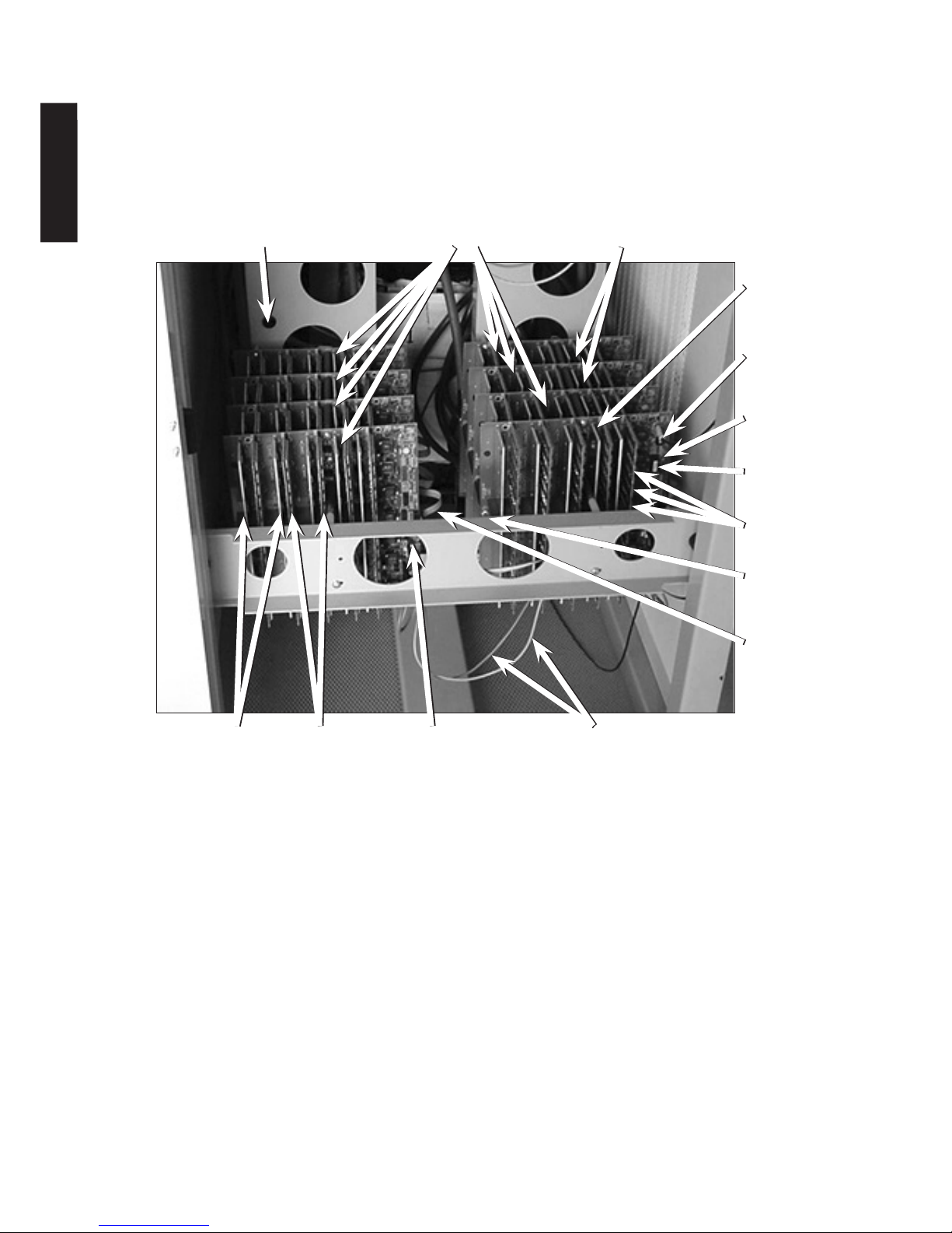
Power PCB replacement procedure (Multiple PCBs per Stack – see Photo)
Ensure the AVR is isolated from the supply and load before commencing
1. Remove front PCB neutral sense cable (Single cable connected to J5)
2. Remove front PCB ribbon cable (connected to J2)
3. Remove Pink/Grey cables (twisted pair to J6)
4. The front PCB is fixed to those behind by hexagonal brass pillars and nuts. To remove the the front PCB
remove these nuts.
5. The same procedure should be repeated until the faulty board is outermost.
6. Replace faulty PCB. If this is the PCB with the transformer cables attached then the above procedure for single
PCB per stack should be followed here. Ensure that the replacement PCB is exactly the same type as the
removed PCB ie slave, master, 3 way, 5 way etc.
7. Re-assembling the PCB stack is the reverse of this procedure.
8. It is essential that the On Site AVR Test Procedure following Maintenance/Repair for replaced power PCBs is
followed before the AVR is put back on-line.
THREE PHASE AUTOMATIC VOLTAGE REGULATOR Issue: Jan 2016 Page 25
ENGLISH
Page 26 THREE PHASE AUTOMATIC VOLTAGE REGULATOR Issue: Jan 2016
In the large AVRs the main circuit boards are type ST165. There is one master PCB per phase and several slaves.
In the picture below of an AVR3x400, there is one master and 7 slave PCBs.
Notes.
1. The Pink/grey wire brings low voltage ac from a small winding on the main transformer to power the circuit
boards. It connects first to one PCB, and then links to all the rest.
2. The ribbon cable takes the control signals from the maser PCB and links it to all the slave PCBs.
3. There are seven round input LEDs on each PCB. These should all be on the same position for the PCBs on any
one phase.
4. The Reset LED will only be on when the mains power is too low to operate the circuit boards correctly.
7 Slave PCBs (ST165)
Pink/Grey fuse (in
line on older units).
Brass pillars
with sleeving
1 Master PCB
(ST165)
Neutral
Connection
Output LEDs
Micro
Input LEDs
Live-Out
Screw
Ribbon Cable
Reset LED (one
on every PCB)
Triacs on
heatsinks
ST163 Resistor
PCBs
Pink/Grey Wires
ENGLISH
 Loading...