

Page 1
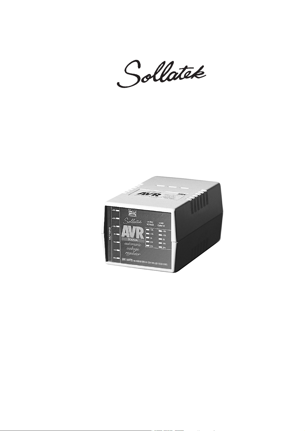
Automatic Voltage Regulator
The AVR Range
Microprocessor Controlled Regulator
IMPORTANT: This manual contains important safety instructions.
Keep this manual handy for reference.
TM
Page 2
CONGRATULATIONS on your choice in selecting the Sollatek Automatic Voltage
Regulator (AVR). We trust that the unit will give you years of trouble free operation.
Section Page
Safety 2
Description 3
Specifications Table 4
Technical Specifications 5
Un-Packing & Inspection 5
Installation 6
Operating Sequence 8
Troubleshooting 9
Warranty & Returns 10
Guarantee 10
Before using the AVR please read all instructions carefully.
Keep these instructions for future reference.
Safety
• All equipment designed and manufactured by Sollatek (UK) Ltd complies with the
latest safety codes of practice. You should still follow all safety instructions and
use caution when installing and operating electrical equipment.
• To avoid the risk of shock, DO NOT expose this equipment to rain, moisture or
liquid spillage.
• Before attempting to use the AVR (Automatic Voltage Regulator) ensure that the
total loading of your equipment does not exceed the maximum rating of the AVR.
To check the rating of your AVR, refer to the label on the back of the unit.
• For your own safety, do not insert any object into the ventilation slots.
• Do not attempt to dismantle the AVR, to do so will invalidate the guarantee. There
are no user serviceable parts inside.
!Most computers power supplies have irregular current wave forms. The Sollatek AVR
can misinterpret this waveform, resulting in an inaccurate load LED display. It is
therefore important not to overload the AVR by checking the maximum current
consumptionof your PC and ensuring that this is below the rating of the AVR.
2
Contents
Page 3
Description
As both high and low mains voltage can damage your electrical equipment, the Sollatek
AVR is designed to monitor and correct the incoming supply continuously.
If the mains voltage rises or drops, the AVR will stabilise the output to ensure that the
voltage reaching your equipment remains constant at 230V +4% (or 110V +4% for US
voltage systems), within the operating range of the unit. see below.
The AVR also protects your electrical equipment against power spikes and surges. By
using the AVR you will ensure a stable voltage supply to your equipment.
Depending on the rating of the AVR, it is suitable for all electrical and electronic appliances,
including:
Computers, TV and Hi-fi, Video, Satellite Receivers, Laboratory electronic instruments,
Coolers, Freezers, Fridges, Air conditioners and any other electric and/or electronic
appliance.
The input/output voltages characteristics of the AVR are
illustrated in the table shown;
The Sollatek AVR’s model numbers indicate the input
voltage, output voltage and the current rating. For
example;
AVR02-22 is rated at 2Amps and the 22 indicate 220V
input and 220V output.
Similiarly;
AVR02-11 indicates a unit rated at 2Amps and 110V
input and 110V output.
While;
AVR02-21 indicates a unit rated at 2Amps with input
of 220V and output of 110V.
The Sollatek AVR has a modern state of the art 7 LED
display to indicate the state of the input at all times and 5
LEDs to indicate the output voltage going to your load.
The Loading on the AVR is indicated by a further 5 LEDs.
3
Input Output
155 213
165 227
175 222
185 235
195 229
205 222
210 227
215 233
225 225
235 235
240 240
245 226
255 235
265 226
275 234
285 243
290 247
AVR Input vs.
Output voltage range
--
Page 4
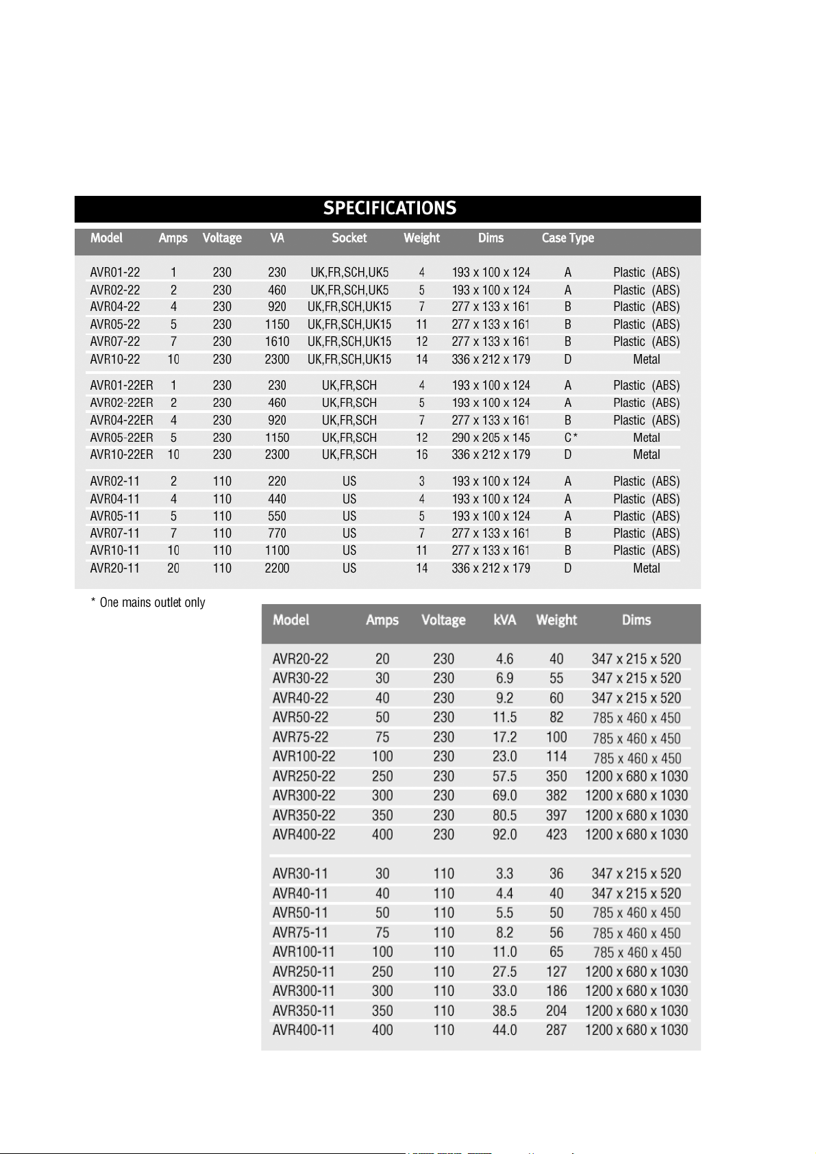
Specifications Table
4
Page 5
Technical Specifications
The following table illustrates the technical specifications for the entire Sollatek
AVR range.
Technical Specifications 230V 115V
Stabilisation
Input -27% to +21% (161-281V) (81-140V)
Output + 4% (221-239V) (110-120V)
Frequency 50/60Hz
45-60Hz continuous
Down to 30Hz for 1-2 seconds
Response Time Within 0.1 second. Up to 1250V per second
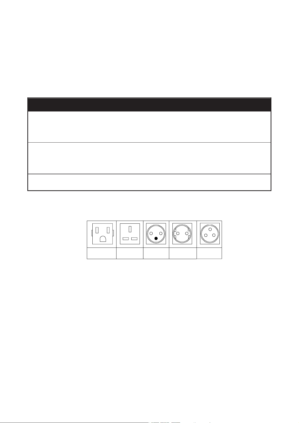
The following diagram illustrates the various sockets available.
Socket Availability
Unpacking & Inspection
After removing the polystyrene protective packaging from the AVR unit, inspect the
ventilation slots to ensure that they are free from all obstruction. Use a vacuum cleaner to
dislodge any obstructions.
Retain the box and packaging material to return the AVR unit in the unlikely event of its
operational failure.
5
US UK FR SCH 15A
Page 6

Installation
WARNING: This appliance must be earthed.
If your mains outlet only has a 2-pin socket, consult a qualified electrician.
If you are unfamiliar with installing electrical equipment consult a qualified electrician.
If a suitable electrical plug is not already fitted to the AVR unit, one should be fitted as
follows:
- The wire coloured BLUE must be connected to the terminal marked ‘N’ for Neutral.
- The wire coloured BROWN must be connected to the terminal marked ‘L’for
Live.
- The wire coloured YELLOW and GREEN must be connected to the Terminal
marked ‘E’ (or ) for Earth.
Locating the AVR: Although the unit does not produce excessive heat, ensure that it is
positioned so that a free flow of air allows the unit to cool.
Do not install inside a closed cupboard and do not allow papers or other materials to be
piled on top.
OPERATING INSTRUCTIONS:
Follow the procedure below to connect your AVR and appliance;
1. Turn your equipment OFF and unplug it from the wall socket.
2. Ensure that the switch on the AVR is OFF.
3. Plug the AVR into the wall socket and plug your equipment into the AVR.
4. Turn the power ON at the wall socket.
5. Turn the AVR switch ON.
6. Turn your equipment ON.
7. The AVR will immediately relay power to your equipment.
8. The LEDs give you a visual indication of the input and output voltage.
9. If the mains voltage is 230V (ie normal) the green 0% input voltage and green 0%
output voltage LEDs will both be lit.
6
Page 7

7
Cable entry holes.
DigitalVoltage/Current display
AVR
AVR
VOLTAGE
OUTPUT CURRENT
INPUT
OUTPUT
SELECT
Internal terminal connection board
Internal terminal connection board
SOLLATEK
MICROPROCESSOR CONTROLLED
AUTOMATIC VOLTAGE REGULATOR
Two LEDs showing the selected
voltage display mode
Switch to select
the output
display between
input voltage or
output voltage
Display showing output voltage or
input voltage in real time
Display showing load current
in real time
10. Any variation to the incoming mains voltage, up or down, will be monitored and adjusted
by the AVR. For full details refer to the Operating Sequence.
The AVR20-22,AVR30-22 & AVR40-22, AVR30-11 and AVR40-11 are enclosed in the Tower
case. Installation is made simple by removing the protective cover from the back of the unit.
All connections are marked on the internal terminal connection board.
The AVR50-22, 75-22 and 100-22
are enclosed in the following case:
• Please ensure that you use
correctly rated cable.
• Input cable should be rated at 1.5
times the output current.
• Increase the cable size for better
regulation.
• This unit must be earthed.
• This unit requires a neutral.
• A suitable circuit breaker (at least
1.5 times unit’s rating in Amps)
should be connected on the input.
Page 8

8
Operating Sequence
1. Input voltage increase is displayed in steps of +5% and
+15% and input voltage decrease is displayed in steps of
-5%, -10%, -20% and -25%.
The AVR indicates the plus or minus voltage variation by
lighting the relevant LED.
2. Within this range, the AVR will compensate by stepping up
or stepping down the output voltage to maintain it’s norm of
230V +4%, which will be indicated by the green 0% LED.
3. If however the input voltage falls below -27%, the AVR will increase the output voltage
accordingly. The amount to which the voltage is lowered will be indicated by the yellow
-10% or red -20% LED.
4. Equally, if the input voltage rises above +18% (272V) the AVR will decrease the output
voltage, indicated by the +5% or +10% LED.
5. If the incoming voltage supply drops below the operating range of the AVR (110V or 55V
for 110V unit) it will shut down the output to the appliance and the 0% Load current LED will
be lit. When first switching on the AVR, it will require a minimum of 175V to power up. If the
input voltage is below this limit, the AVR will not power up the load and the 0% Load current
LED will be lit.
6. Stabilisation will be automatically reinstated to your appliance as soon as the input voltage
comes within the operating range of the AVR.
7. The Load display on the output of the AVR indicates the loading of the AVR. For example
the 50% Load LED will be lit if the load takes 0.5 Amp when connected to an AVR250
(250VA or 1Amp). The Sollatek AVR will accept up to 110% load (1.1Amps on the AVR250).
However prolonged overload could result in damage and should be avoided. Over 110%
loading will cause the AVR trip out and switch the appliance off. To correct this switch the
AVR off. Remove the overload and restart the AVR.
-
Page 9

Troubleshooting
• Please consult the above chart before contacting your supplier. Ensure that you
have followed the operating instructions carefully.
• There are no user serviceable parts internally.
• Disassembling the unit, opening the lid or tampering with the unit is unsafe for
unqualified users and will render the warranty invalid.
9
Symptom Possible cause Remedy
The unit does not switch on.
None of the LEDs are lit. 1) The fuse has blown. Change the fuse with a fuse of the correct rating. Ensure that
2) The mains switch is not on. the load current is not exceeding the capacity of the unit. If
3) No power is available on the input. after changing the fuse the unit is still not functioning return
the unit for inspection by your dealer.
Ensure that you are using the correct voltage (i.e. 230V or
110V)
The unit appears to be Load is not plugged in. 1) Check that the load is plugged-in.
functioning normally but the load Load is not switched on. 2) Check that the input voltage is within the input range of the
is not being switched on. AVR.
Load fuse has blown. 3) Check that the Load is switched on.
Overload condition. 4) Check the loading of the AVR. Make sure the load doesn't
exceed the capacity of t he AVR.
The unit appears to be The mains input is too low;
functioning but the output voltage 1) Due to continuous brown-out 1) Wait for the incoming supply to rise to the starting voltage
is persistently low. of the AVR
2) The unit is rated at 230V and the
incoming supply is 110V
The AVR continuously performs 1) Possible internal fault. The fault could 1) Ensure that the load current does not exceed the rating of
self-test. If it finds a fault the be temporary or permanent. the AVR.
LEDs will continously light from
top to bottom repeatedly in one 2) Very bad mains waveform or 2) Turn the appliance off then switch AVR off. Restart the unit
of two patterns. frequency. as per operating instructions.
3) If the above doesn't solve the problem please return the
unit to a Sollatek service centre.
AVR blows fuses. Even though Most computers power supplies have Reduce the loading. Use a larger AVR.
the load LEDs don't show irregular current wave forms. The
overload. Sollatek AVR can misinterpret this
waveform, resulting in an inaccurate
load LED display. It is therefore
important not to overload the AVR by
checking the maximum current
consumption of your PC and ensuring
that this is below the rating of the AVR.
Page 10

Guarantee
Sollatek (UK) Ltd guarantee that if within 2 years of purchase this appliance fails due to
faulty workmanship or materials we will repair or replace it (at our discretion) free of
charge provided that:
• The appliance has been correctly installed and used within the electrical
range as specified on the appliance nameplate.
• The appliance has been used in accordance with the operating instructions.
• There has been no attempt to open the unit for any reason whatsoever.
• The unit is returned to Sollatek or a Sollatek agent in good condition.
• Sollatek shall not be liable under the terms of this guarantee for any material
fault or damage as a result of failure of this appliance.
• This guarantee does not affect your statutory or Common Law rights.
Warranty & Returns
If your AVR unit should need repair, the quickest and simplest way is to return it to your
dealer or to a Sollatek Service Centre or direct to the nearest Sollatek office.
IMPORTANT : Before returning a unit to a Sollatek Service Centre, contact the returns
department to obtain a returns number. You will be asked for the following information
which you should have ready;
Your Name, Address, Telephone, Fax (If Available), Email (If Available)
Date Purchased, Where Purchased
Serial Number, model number, Local voltage and type of load.
Description of Fault
Once you have the returns number, ensure that the unit is securely packed enclosing a
short note with details as above and mark the unit clearly with the returns number.
Remember also to add your name and address.
Complying with the above will ensure that your unit will be treated promptly and efficiently.
Without a returns number it will not be possible to trace a unit or check progress of repair
of the unit.
Sollatek UK Limited.
Unit 10, Poyle 14 Ind Estate,
Blackthorne Road, Poyle, Slough. SL3 0AX, England.
Tel : 01753 688300 Fax: 01753 685306
Technical Support : support@sollatek.com
Sales : sales@sollatek.com
10
Page 11

11
Page 12

Sollatek AVR instruction manual. Revision 3.0. Revised March 2003.
Sollatek AVR
©Sollatek (UK) Limited 1996 All Rights Reserved.
SOLLATEK and the SOLLATEK device are the trade marks of the Sollatek group of companies.
 Loading...