


EZL-200L User’s Manual
Version 1.4
Sollae Systems

- 2 -
To all residents of the European Union
Important environmental information about this product
This symbol on this unit or the package indicates that disposal of this unit after its
lifecycle could harm the environment. Do not dispose of the unit as unsorted municipal
waste; it should be brought to a specialized company for recycling. It is your responsibility to
return this unit to your local recycling service. Respect your local environmental regulation. If in
doubt, contact your local waste disposal authorities.

- 3 -
- Table of Contents -
1. OVERVIEW..................................................................................................................... - 5 -
1.1. O
VERVIEW ......................................................................................................................- 5 -
1.2. C
OMPONENTS..................................................................................................................- 6 -
1.3. S
PECIFICATIONS ..............................................................................................................- 6 -
1.4. I
NTERFACE ......................................................................................................................- 7 -
1.4.1. Power ............................................................................................................................ - 7 -
1.4.2. Dsub Connector ............................................................................................................- 7 -
1.4.3. LEDs.............................................................................................................................. - 8 -
1.4.4. Ethernet Interface.......................................................................................................... - 9 -
2. INSTALLATION AND TEST RUN ............................................................................. - 10 -
2.1. I
NSTALLATION METHOD................................................................................................- 10 -
2.1.1. Checking the Communication Environment................................................................ - 10 -
2.1.2. Connecting to the Network.......................................................................................... - 10 -
2.1.3. Configuring the Environmental Variables................................................................... - 11 -
2.2. T
EST RUN......................................................................................................................- 11 -
2.2.1. Changing PC IP Address............................................................................................. - 11 -
2.2.2. Installation EZL-200L................................................................................................. - 11 -
2.2.3. Configuring EZL-200L................................................................................................ - 11 -
2.2.4. Connecting to the PC Serial Port................................................................................ - 12 -
2.2.5. Communication Test .................................................................................................... - 12 -
3. CONFIGURING IP ADDRESS AND ENVIRONMENTAL VARIABLES .............. - 13 -
3.1. IP
ADDRESS AND ENVIRONMENTAL VARIABLES ............................................................- 13 -
3.2. C
ONFIGURATION BY EZCONFIG .....................................................................................- 17 -
3.2.1. ezConfig Menu ............................................................................................................ - 17 -
3.2.2. Example configuration of ezConfig (LOCAL)............................................................. - 19 -
3.2.3. Example configuration of ezConfig (REMOTE).......................................................... - 21 -
3.3. AT
COMMAND...............................................................................................................- 22 -
3.4. S
ETTING IP ADDRESS-RELATED ITEMS BY DHCP.........................................................- 22 -
3.5. S
ETTING IP ADDRESS-RELATED ITEMS BY PPPOE ........................................................- 22 -
4. OPERATION MODE.................................................................................................... - 23 -
4.1. O
PERATION MODE OVERVIEW ......................................................................................- 23 -
4.1.1. Overview ..................................................................................................................... - 23 -
4.2. H
OW TO INITIATE EACH OPERATION MODE..................................................................- 23 -

- 4 -
4.2.1. How to Initiate Normal Mode ..................................................................................... - 23 -
4.2.2. How to Initiate ISP Mode............................................................................................ - 23 -
4.2.3. Comparison of Operation Modes................................................................................ - 23 -
4.3. N
ORMAL COMMUNICATION MODE................................................................................- 23 -
4.4. ISP
MODE .....................................................................................................................- 24 -
5. NORMAL COMMUNICATION MODE .................................................................... - 26 -
5.1. T2S(TCP
TO SERIAL) ...................................................................................................- 26 -
5.2. AT C
(AT COMMAND)....................................................................................................- 28 -
5.3. COD
(CONNECT ON DEMAND) .....................................................................................- 30 -
5.4. U2S...............................................................................................................................-
32 -
6. ATC MODE ................................................................................................................... - 34 -
6.1. O
VERVIEW ....................................................................................................................- 34 -
6.1.1. AT command format .................................................................................................... - 34 -
6.2. B
ASIC AT COMMAND SET (EXAMPLE: ATA , AT D ETC.) ................................................- 34 -
6.3. E
XTENDED AT COMMANDS (EXAMPLE: AT+ P L I P ETC.) ...............................................- 35 -
6.4. O
NLINE STATE AND ONLINE COMMAND STATE .............................................................- 35 -
6.4.1. Changing Online State to Online Command State ...................................................... - 35 -
6.4.2. Changing Online Command State to Online State ...................................................... - 36 -
6.5. E
XAMPLE OF CONFIGURATION WITH AT COMMAND......................................................- 36 -
6.6. E
XAMPLE OF TCP CONNECTION ...................................................................................- 36 -
6.6.1. Example of Active Connection .................................................................................... - 36 -
6.6.2. Example of passive Connection................................................................................... - 37 -
6.7. E
XAMPLE OF TCP DISCONNECTION ..............................................................................- 37 -
6.7.1. Example of active disconnection ................................................................................. - 37 -
6.7.2. Example of passive disconnection............................................................................... - 37 -
7. TECHNICAL SUPPORT, WARRANTY, AND NOTES ON OPERATION............. - 38 -
7.1. T
ECHNICAL SUPPORT ....................................................................................................- 38 -
7.2. W
ARRANTY ..................................................................................................................- 38 -
7.2.1. Refund ......................................................................................................................... - 38 -
7.2.2. Free Repair Services ................................................................................................... - 38 -
7.2.3. Charged Repair Services............................................................................................. - 38 -
7.2.4. Notes on Operation ..................................................................................................... - 38 -
8. REVISION HISTORY.................................................................................................. - 40 -

- 5 -
1. Overview
1.1. Overview
Along with the development of the Internet, the demand for data communication
functions has increased recently. Data communication over the Internet requires using
TCP/IP, the Internet communication protocol. That is to say, in order to connect a
system to the Internet, TCP/IP protocol must be implemented. It is possible to
implement TCP/IP by directly implementing the protocol, porting public TCP/IP, or
using Operating System (OS). However, all these methods impose burdens on the
developer in time, cost, and technology.
ezTCP series, a Serial ↔ TCP/IP protocol converter product group of Sollae Systems,
enables you to use TCP/IP communication (the Internet communication) function simply
by “connecting the cable to a serial port”. ezTCP sends data from the serial port to the
Internet network after TCP/IP processing, and vice versa.
EZL-200L in ezTCP product group is a product that provides TCP/IP communication
through Ethernet. In other words, like other ezTCP products, EZL-200L sends data from
the serial port to the LAN after TCP/IP processing and vice versa.
It provides DHCP and PPPoE functions as well as TCP/UDP/IP, so that it can be applied
to the cable network and the xDSL network.
EZL-200L is low-cost TCP/IP solution that is integrated highly and optimally in a small
hardware.

- 6 -
1.2. Components
z EZL-200L Body
z 5V Power Adopter (Option)
z RS232C cable for PC connection (Option)
z Cross-over Ethernet cable (Option)
1.3. Specifications
Input Voltage
5V (±10%)
Power
Current 78mA typical
Dimension 136mm x 83mm x 29mm
Weigh t About140g
Serial 9pin Dsub male
Interface
Network 10- Base T
Serial Port RS232 (1200bps ~ 115200bps)
Network 10Base-T
Protocols TCP, UDP, IP, ICMP, ARP, DHCP, PPPoE
T2S TCP Server Mode
COD TCP Client Mode
AT C
TCP Server/Client Mode
(AT command emulation)
Communicat-
ion Mode
U2S UDP
ezConfig Configuration utility via LAN
ezterm Socket test utility
Utilities
hotflash Firmware download utility via TFTP
) You can download free utilities and firmware from http://www.eztcp.com.

- 7 -
1.4. Interface
1.4.1. Power
DC 5V is used for EZL-200L and the specification is below:
1.4.2. Dsub Connector
The connector of serial port is 9 pin Dsub male. The specification is below:

- 8 -
z RS-232
# name description level Dir. Etc.
1 -
- -
-
-
2 RXD
Receive Data RS232
Input
Mandatory
3 TXD
Transmit Data RS232
Output
Mandatory
4 DTR
Data Terminal Ready -
-
DTR/DSR
loopback jumper
5 GND
Ground Ground
-
Mandatory
6 DSR
Data Set Ready -
-
DTR/DSR
loopback jumper
7 RTS
Request To Send RS232
Output
Optional
8 CTS
Clear To Send RS232
Input
Optional
9 -
- -
-
-
Pin 4 and pin 6 will be loop-backed when JP2 is on. JP2 is inside of EZL-200L.
1.4.3. LEDs
EZL-200L has 5 LEDs.
Each LED functions as follows:
Name Meaning Color LED Status Description
PWR Power Red ON
Power is supplied
Blinking for
a second
IP is allocated but TCP connection is
not established
Blinking 4
times/sec
IP is not allocated
ON
TCP connection is established
STS Status Yellow
Rapidly
Blinking
ISP Mode
LINK
LAN
Link
Green
ON
Connected to ethernet
RXD LAN Rx Yellow
Blinking
There are data on the LAN

- 9 -
TXD LAN Tx Green
Blinking
Packets are being transmitted to
Ethernet
1.4.4. Ethernet Interface
The interface of EZL-200L is 10Base-T. 1:1 cable should be used for connection with a HUB
and cross-over cable should be used for connection with PC directly without any HUB.
Each piece of Ethernet equipment has unique hardware addresses, and EZL-200L also
has factory-set hardware address (which is called MAC address).

- 10 -
2. Installation and Test Run
2.1. Installation Method
You can install EZL-200L in the following steps:
Title Item Sub-item Description
IP address environment
3.1.
Serial port settings
3.1.
1.
Checking the
communication
environment
Check items
Application program to be
used
4.
2.
Connecting to the
network
Check method
Check if LINK LED is
ON.
1.4.4.
Set by ezConfig, a utility
program for configuration
through the network.
3.2.
Configuration
method
Set by AT commands in
ATC mode
6.
IP address related items
3.1.
Serial port related items
3.1.
3.
Configuring the
environmental
variables
Configuration
items
Communication mode
(Decided depending on
application program)
4.
4. Application to the field
2.1.1. Checking the Communication Environment
Before installing EZL-200L, check the network environment where EZL-200L is to be
installed, including the followings matters:
z IP address environment (local IP, subnet mask, gateway, etc.)
z Serial port items of the equipment to which EZL-200L is going to be
connected (baud rate, data bit, parity, stop bit)
z Application program protocol to be used (TCP/UDP, server/client, SSL, etc.)
z For application program protocol to be used, see “5. Normal Communication
Mode”.
2.1.2. Connecting to the Network
Connect power to EZL-200L, and connect EZL-200L directly to the Ethernet port of the

- 11 -
PC where test is to be performed with a cross-over Ethernet cable.
2.1.3. Configuring the Environmental Variables
When network connection is completed, configure the environmental variables such as
IP address related items, serial port related items, and communication mode related
items through the LAN using “ezConfig,” the environmental variable configuration
program.
) For environmental variable configuration, see “3. Setting IP Address and
Environmental Variables.”
2.2. Test Run
You can perform test run according to the following orders. The test run described here
is based on the assumption that the IP address of the PC is set to 10.1.0.2.
2.2.1. Changing PC IP Address
You can change the IP address of your PC as follows:
IP Address 10.1.0.2
Subnet Mask 255.0.0.0
Gateway IP Address 0.0.0.0
2.2.2. Installation EZL-200L
Connect the supplied RS232 cable between your PC and EZL-200L, the LAN cable to
the hub to which the PC is connected or directly to the PC with a cross-over cable, and
the supplied EZL-200L power adapter to EZL-200L for power supply. If the LAN cable
has been correctly connected when power is supplied, LINK LED turns on.
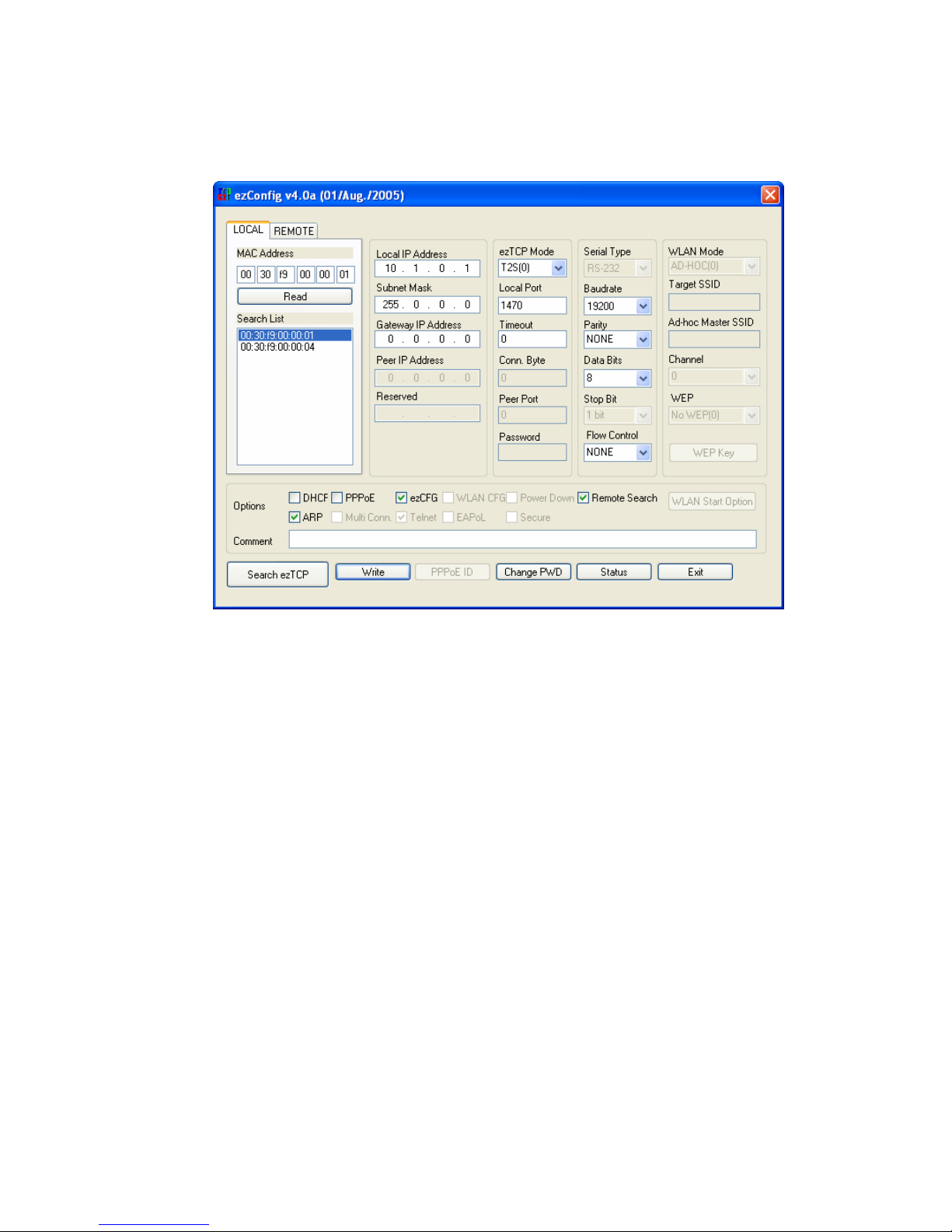
2.2.3. Configuring EZL-200L
Configure EZL-200L setting using ezConfig, the ezTCP configuration program, as
follows.
Run ezConfig, and click [Search ezTCP] button in the ezConfig window. And, ezConfig
program will search all ezTCPs on the local network.
When ezTCP is searched, MAC address of the ezTCP is displayed on the [Search List]
window (The MAC address is indicated at the bottom of the product case).
Select the corresponding MAC address, and set the same as shown in the following
figure and click [Write] button to save the settings.
- 12 -
.
2.2.4. Connecting to the PC Serial Port
Connect the serial port of your PC and that of EZL-200L, using the supplied serial
communication cable. Then, run serial communication program such as Hyper Terminal
and Teraterm. When the program is run, select the same serial port values as those set to
EZL-200L [19200bps, data bit: 8 bits, stop bit: 1 bit, no parity], which will finish the
preparation for serial communication.
2.2.5. Communication Test
When the preparation for serial communication is finished, enter the following in the
DOS window on your PC, to connect to TCP through Telnet program.
"Telnet 10.1.0.1 1470"
When TCP connection succeeds, STS LED of EZL-200L turns ON.
When the STS LED turns ON, enter “123” on the Telnet window, and "123" will appear
on the hyper terminal. Enter “ABC” on the hyper terminal, and “ABC” will appear on
the Telnet window. Otherwise, communication test fails.
.

- 13 -
3. Configuring IP Address and Environmental
Variab l e s
3.1. IP Address and Environmental Variables
For TCP/IP communication, you must set IP address related items. In addition, you have
to set serial port related items (baud-rate, data bit length, parity bit, flow control, etc) to
EZL-200L.
You can set the IP address and the serial port related items by using ezConfig, the
supplied configuration utility which allows you to configure your EZL-200L over the
network, or by using AT commands in ATC mode.
Item Description
Local IP
Address
IP address of EZL-200L
Subnet Mask Subnet mask
Gateway IP
Address
IP address of gateway
Local Port
Port number for waiting to be
connected in Server mode
Port number for waiting UDP data
Peer IP Address
IP address to connect in Client mode
IP address to send data in UDP mode
Peer Port
Port number to connect in Client mode
Port number to send data in UDP mode
IP Address-related
Items
Permitted IP
Address
Permitted IP address in server mode.
Baudrate Serial Port Speed(bps)
Data bits Data bit length
Parity Parity
Stop bit Stop bit
Serial Port
Flow Control Flow control
Communication Mode ezTCP Mode Communication Mode

- 14 -
Conn. Byte
Minimum number of bytes attempting
to connect/transmit
Connect/Disconnect
Event
Timeout Limit time to keep connection
ezConfig Enable ezConfig function.
Remote Search
Remote configuration function with
UDP unicast
Password
Select between Telnet password and
ezConfig password.
Configuration Method
Used
ARP Enable IP setting by ARP.
DHCP
Select to receive EZL-200L IP address
as DHCP.
PPPoE
Select to receive EZL-200L IP address
as PPPoE.
Dynamic IP Address
PPPoE ID &
Password
ID and password to be used for PPPoE
z Local IP Address
IP address of EZL-200L. If you set DHCP or PPPoE is set, an IP address is
automatically allocated. So, you cannot set the local IP address.
z Subnet Mask
Sets subnet mask of the network where EZL-200L is installed
z Gateway IP Address
Sets the gateway IP address of the network where EZL-200L is installed.
z Permitted IP Address
It is a permitted IP address of foreign host when EZL-200L operates as a server. The
only host that is written in this item can connect to EZL-200L. If Permitted IP Address is
0.0.0.0, all hosts can connect to the EZL-200L.
z Local Port
Port number, which is used as TCP port number waiting to be connected when EZL-
200L operates as TCP server or as the port number waiting for UDP data when it
operates in U2S communication mode.

- 15 -
z Peer Port
Local port number of the server to connect when EZL-200L operates as TCP client or to
transmit UDP data when it operates as U2S
z Baudrate
Selects a serial port speed (1200 bps 115200bps).
z Data bits
Selects a data bit length of the serial port (7 bits or 8 bits)
z Parity
Select a parity bit of the serial port (None, Even, Odd).
z Stop bit
Selects a stop bit length of the serial port (1 bit, 2 bits).
z Flow Control
Selects flow control for the serial port (None, RTS/CTS, Xon/Xoff).
z ezTCP Mode
Selects the communication mode of EZL-200L (T2S, ATC, COD, U2S).
z Conn. Byte
Decides a point of time to start connection when EZL-200L operates as COD. EZL-200L
starts to connect to the host (Peer IP Address and Peer Port) of the designated host upon
receiving as many data as specified by [Conn. Byte] from the serial port.
z Block(Byte)
Decides the size of UDP packet to be sent at a time when EZL-200L operates as U2S.
z Timeout
When EZL-200L operates as TCP such as T2S, COD and ATC, connection is closed if
data communication is not continued as long as the time set to this item unless this item
is set to 0 (unit: second)

- 16 -
z Interval
When EZL-200L operates as UDP like U2S, it transmits data in blocks by gathering data
for the time set to this item (unit: 10ms)
z ezConfig
You can use ezConfig utility only this item is enabled.
(If this item is not enabled, you cannot set EZL-200L using ezConfig. Therefore, it is
recommended to enable this all the times.)
To enable ezConfig, set this item in ISP mode.
z Remote Search
If this item is set, EZL-200L in other network can be configured by ezConfig. Remote
Search function is performed in the [REMOTE] tab.
z Password
Sets a password for configuring with ezConfig. If user forgot the password, the user can
delete the password in ISP mode.
z ARP
When this item is selected, EZL-200L uses the destination IP address of the first packet
coming to its MAC address as its own IP address temporarily. This item should be set in
DHCP environment if required.
z DHCP
Set to receive an IP address as DHCP.
z PPPoE
Set to receive an IP address as PPPoE.
z PPPoE ID & Password
Sets ID and password used for PPPoE.
EZL-200L uses maximum 32 byte for saving an ID and 8 bytes for a password.
z Comment
Stores maximum 32 byte user comment on the product. This item helps the user
distinguish each EZL-200L more easily.

- 17 -
3.2. Configuration by ezConfig
3.2.1. ezConfig Menu
The basic environmental variables (IP address related items, serial port items, and etc.) can
be set by ezConfig which is an integrated management tool for Windows.
ezConfig is operated in Microsoft Windows(Windows 98, 98 SE, 2000 Pro, ME, XP
Pro/Home). Following is the screen shot of ezConfig which is just launched.
√ ezConfig can set not only EZL-200L’s environmental variables but also other ezTCP
series.
ezConfig configures ezTCP by Ethernet, there are two way to configure.
The first way is UDP broadcast. When using UDP broadcast, user can search all ezTCPs in
the same network without knowledge of IP address. But beware that it can be used in the
‘same network’. This method performed in the [LOCAL] tab of ezconfig version above 4.0.
The second way is UDP unicast that communicates by IP address. As it configured with IP
address, EZL-200L is configured any place if they are connected with network. This method
performed in the [REMOET] tab of ezconfig version above 4.0.
(ezConfig below version 4.0 supports only UDP broadcast)

- 18 -
LOCAL REMOTE
communication UDP broadcast UDP unicast (port: 50005)
search With MAC address with IP address
location
In the same network with EZL-
200L
Can be used in a different
network
The functions of ezConfig’s buttons are followed:
This button is used to search for all of the network-attached ezTCPs.
The search results will be displayed on the [Search List] box and you can select an item
using a mouse or cursor as required. The value displayed on the box indicates the MAC
ADDRESS of each ezTCP. The selected setup value of ezTCP will be displayed on the
right side.
[LOCAL]tab:.
You can see only the ezTCP configuration values if you press this button after entering
the 6-digit hexadecimal number printed on the ezTCP main body in the MAC
ADDRESS box. It is useful when there are too many ezTCPs attached to the network to
search for one from the LIST box.
[REMOTE] tab:
Reading environmental variables with the IP address.
This button is used to save the changed value in ezTCP after modifying
the configuration. Make sure not to press this button during operating ezTCP since
ezTCP will automatically be reset right after its environment setup value is saved.
Otherwise, it may cause malfunction.
Terminating ezConfig.
ezTCP provides User Authentication function to prevent an unwanted
person from modifying the configuration. The authentication process is performed
through the password string verification. When entering or changing the password
strings, you can use this button. Changing the ezTCP configuration details if a password

- 19 -
has been entered requires the proper password to be entered in the PASSWORD field.
√ If you forget the password, erase or reenter in ISP Mode.
This button is used to read a dynamic status during operating ezTCP.
Pressing this button will display a new window, where the time-elapsed after the power
is on, the current IP address, and the data throughput of the serial port are indicated.
Double-clicking each item on the [Search List] will carry out the same function.
3.2.2. Example configuration of ezConfig (LOCAL)
ezConfig can be used to change the IP address related items, the serial port setup value,
the serial port operation mode. This section describes these functions briefly. For more
information, see the following sections.
The following example shows how to read and change ezTCP's basic functions. Try
changing ezTCP setup value according to the following sequence
z When the ezTCP power is turned on and the LAN cable is connected correctly,
pressing [Search] or [Read] button will display the following window:
z If a network-attached ezTCP is detected, the following message will be
displayed. If a message pops up indicating that there is no response from ezTCP,
check that the power is turned on and the cable is connected correctly, then try
pressing [Search] or [Read] button.
√ It is impossible to use ezConfig, if EZCFG check box is disabled. This function can be

- 20 -
re-enabled in ISP mode.
z If more than one ezTCP are detected, ezTCP's MAC ADDRESS will be
displayed in the [Search List] box on ezConfig. Check if the MAC ADDRESS
displayed in the [Search List] window corresponds to that printed on ezTCP
main body. The following screen shows this process:
Following is the screenshot when ezTCPs were found.
z Set [ezTCP Mode], [Local IP Address], [Local Port], and serial port related items.
After setting press [Write] button. If there is any error during writing process, check
the LAN between PC and EZL-200L.
z Check if the set IP address is correct with ping command in DOS prompt.
Following is the message if the IP address is OK. If "Request timed out" message is
shown, check IP address.
.

- 21 -
C:\>ping a.b.c.d
Pinging a.b.c.d with 32 bytes of data:
Reply from a.b.c.d: bytes=32 time=1ms TTL=64
Reply from a.b.c.d: bytes=32 time=1ms TTL=64
Reply from a.b.c.d: bytes=32 time=1ms TTL=64
Reply from a.b.c.d: bytes=32 time=1ms TTL=64
<When IP address is a.b.c.d.>
√ IP address, subnet mask, and gateway IP address of both PC and EZL-200L should be
correct to succeed in ping test.
3.2.3. Example configuration of ezConfig (REMOTE)
z Input the IP address of EZL-200L in IP address field in the [REMOTE] tab,
and press [Read] button. Then following window will be appeared.
z If the EZL-200L is found, the following will be shown.

- 22 -
z Configure variables and press [Write] button.
3.3. AT command
In ATC mode, the user can set environment variables through the serial port using AT
command.
) For more information, See “6. ATC Mode”.
3.4. Setting IP Address-related Items by DHCP
Under environment with a network operating a DHCP server, DHCP protocol allows
the user to automatically set the IP address, subnet mask, gateway, and name server of
ezTCP. Using DHCP automatic setup function requires the user to check [DHCP] item
on ezConfig. Note that the user may have to check [ARP] item according to the type of
DHCP servers.
3.5. Setting IP Address-related Items by PPPoE
PPPoE is used in most ADSL and VDSL. To use PPPoE function, PPPoE function should be
enabled and PPPoE ID and PPPoE password should be configured. The local IP address of
EZL-200L is assigned automatically in PPPoE environment.
√ Some ADSL or VDSL modem use DHCP. Please contact your ISP (Internet Service
Provider).

- 23 -
4. Operation Mode
4.1. Operation Mode Overview
4.1.1. Overview
EZL-200L can operate in one of two modes (normal and ISP modes). Normal mode is
ordinary data communication mode; and ISP mode is used to download EZL-200L
firmware through the Ethernet(TFTP).
4.2. How to Initiate Each Operation Mode
4.2.1. How to Initiate Normal Mode
Normal mode is a mode in which EZL-200L performs its original functions. If you do
not make any change in the default setting, EZL-200L usually operates in normal mode.
) For more information, see “5. Normal Communication Mode.”
.
4.2.2. How to Initiate ISP Mode
Supply power to EZL-200L with pressing the ISP button on the back of the product, and
EZL-200L operates in ISP mode
. During ISP mode, the STS LED of EZL-200L will be
blink rapidly.
4.2.3. Comparison of Operation Modes
The following table is the comparison of the above described operation modes.
Mode How to Initiate Description Serial Port
normal -
Normal data communication mode
T2S, ATC, COD, U2S
User setting
ISP
Supply power
with pressing the
button or press
the button about
2 seconds
Download firmware through the
ethernet
19200bps,N,8,1
4.3. Normal Communication Mode
Normal communication mode is suitable for the purpose of using EZL-200L.
Normal communication mode can be classified into four modes – T2S, ATC, COD, and
- 24 -
U2S – each of which is described in the following table.
Communication
Mode
Protocol Connection
Need for User
Equipment
Software
Modification
Configuration of
Environmental
Variables through
Serial Port
Topology
T2S TCP
Passive
Connection
Not needed Impossible 1:1
ATC TCP
Active/Passive
Connection
Needed Possible 1:1
COD TCP
Active
Connection
Not needed Impossible 1:1
U2S UDP No Connection Not needed Impossible N:M
TCP protocol requires connection process. The connection is always established as 1:1
connection. At this time, the host waiting for connection (passive connection) is called a
server and the one attempting to connect (active connection) is called a client.
On the other hand, UDP communicates by block unit without connection process. As UDP
does not require connection, numbers of hosts can communicate at the same time.
) For more information on communication modes, refer to the next chapter.
4.4. ISP Mode
In ISP mode, you can download the latest firmware (EZL-200L operation software)
provided by our company.
The following section describes how to download firmware in ISP mode.
z
Supply power to EZL-200L with pressing the ISP button on the back of the
product. Then, the STS LED will be blink rapidly.
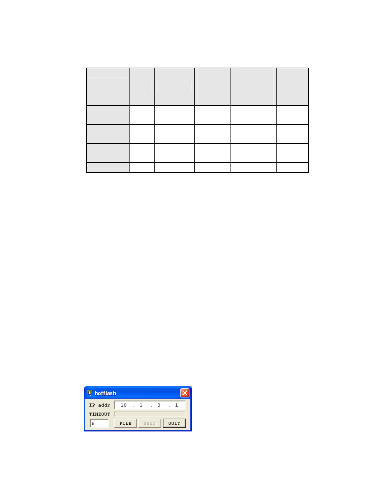
z Run hotflash that is supplied by us.

- 25 -
z Select a firmware in the [FILE] menu, and input the IP address of EZL-200L
and press [SEND] button. Then the firmware will be transferred by Ethernet.
z After completion, a message that informs the firmware was downloaded
successfully. And EZL-200L reboots automatically and run in Normal Mode. In
Normal Mode, STS LED is blink every 1 second.

- 26 -
5. Normal Communication Mode
5.1. T2S(TCP To Serial)
When a host connects to predefined local port, the EZL-200L accepts a TCP
connection. When the EZL-200L accepts TCP connection, then the TCP connection is
established. After connection is established, TCP/IP processing is performed on the
data coming to the serial port, which is then transmitted to the remote host. And the
TCP/IP data coming from the remote host is TCP/IP-processed and transmitted to the
serial port to establish data communication. (Data coming to the serial port before TCP
connection is established will be ignored.)
To limit the peer host, user should set [Peer IP Address]. The only pre-defined host can be
accessible. If [Permitted IP Address] is 0.0.0.0, any host can connect to EZL-200L.

- 27 -
Set the following for T2S mode:
Item Description
Local IP Address IP address of EZL-200L
Subnet Mask Subnet mask
Gateway IP
Address
IP address of gateway
Local Port
Port number for waiting to be
connected in Server mode
IP Address Relate
Items
Permitted IP
Address
Permitted host to connect
(if set to 0.0.0.0, any host can connect)
Baudrate Serial port speed (bps)
Data bits Data bit length
Parity Parity
Stop bit Stop bit
Serial Port
Flow Control Flow control
Communication
Mode
ezTCP Mode Communication Mode (T2S(0))
Disconnection Timeout Limit time to keep connection
ezConfig Enable ezConfig function.
Configuration
Method
Password ezConfig password.
DHCP
Select to receive EZL-200L IP address
as DHCP.
Dynamic IP
PPPoE
Select to receive EZL-200L IP address
as PPPoE.

- 28 -
5.2. ATC (AT Command)
In ATC mode, the user can control the EZL-200L in a similar way to controlling the
modem using AT command. In ATC mode, only a TCP connection is possible and both
the server and the client can be configured.
In ATC mode, the AT command allows the user to set environment variables including
the IP address and control TCP connection and
disconnection.

- 29 -
Set the following for ATC mode.
Item Description
Local IP Address
IP address of EZL-200L
Subnet Mask
Subnet mask
Gateway IP
Address
IP address of gateway
Local Port
Port number for waiting to be connected in
Server mode
Peer IP Address
Peer IP address to connect
IP Address
Relate Items
Peer Port
Peer port number to connect
Baudrate
Serial port speed (bps)
Data bits
Data bit length
Parity
Parity
Stop bit
Stop bit
Serial Port
Flow Control
Flow control
Communication
Mode
ezTCP Mode
Communication mode(ATC(1))
Disconnection
Timeout
Limit time to keep connection
ezConfig Enable ezConfig function.
Configuration
Method
Password ezConfig password.
DHCP
Select to receive EZL-200L IP address as
DHCP.
Dynamic IP
PPPoE
Select to receive EZL-200L IP address as
PPPoE.
) See “6. ATC Mode.”

- 30 -
5.3. COD (Connect On Demand)
In COD mode, the EZL-200L functions as a client.
When data of the pre-specified size [CONN BYTE] comes to the serial port, the EZL-
200L attempts a TCP connection to the TCP port [PEER PORT] of the preset host IP
[PEER IP ADDRESS]. If the remote host accepts the TCP connection, TCP connection
will be established. Data coming to the serial port after connection establishment is
TCP/IP-processed and transmitted to the remote host. And, data coming from the
remote host is TCP/IP-processed and transmitted to the serial port for data
communication.

- 31 -
Set the following for COD mode.
Item Description
Local IP Address
IP address of EZL-200L
Subnet Mask
Subnet mask
Gateway IP
Address
IP address of gateway
Peer IP Address
Peer IP address to connect
IP Address
Related Item
Peer Port Peer port number to connect
Baudrate
Serial port speed (bps)
Data bits
Data bit length
Parity
Parity
Stop bit
Stop bit
Serial Port
Flow Control
Flow control
Communication
Mode
ezTCP Mode
Communication mode(COD(2))
Conn. Byte Bytes for starting to connect
Connection/
Disconnection
Timeout
Limit time to keep connection
ezConfig
Enable ezConfig function.
Configuration
Method
Password ezConfig password
DHCP
Select to receive EZL-200L IP address as
DHCP.
Dynamic
IP Address
PPPoE
Select to receive EZL-200L IP address as
PPPoE.

- 32 -
5.4. U2S
U2S mode allows for UDP communication.
In UDP mode, data are transmitted in blocks, which requires dividing data coming to the
serial port into blocks before transmitting data. A procedure for dividing data into
blocks is as follows:
If data of pre-specified bytes [Conn. Byte] comes to the serial port of the ezTCP or if a
specified period of time [TIMEOUT] elapses after first data reception, all data received
for the same period is recognized as one block which is then transmitted to the
UDP. The [TIMEOUT] unit is 10ms. If [TIMEOUT] is set to 2, the time period is
between 20ms and 30ms.
Since UDP communication does not require a connection procedure, the user can
establish N-to-M communication via multicast and broadcast.
.

- 33 -
Set the following for U2S mode.
Item Description
Local IP
Address
IP address of EZL-200L
Subnet Mask
Subnet mask
Gateway IP
Address
IP address of gateway
Local Port
Port number for UDP data receving
Peer IP
Address
Peer IP address to transmit
IP address
Related Item
Peer Port
Peer port number to transmit
Baudrate
Serial port speed (bps)
Data bits
Data bit length
Parity
Parity
Stop bit
Stop bit
Serial Port
Flow Control
Flow control
Communication
Mode
ezTCP Mode
Communication mode(U2S(3))
Block
UDP block size to transmit (unit: byte)
Packets
Interval
Data gathering time from serial port to
transmit as UDP (unit:10ms)
ezConfig
Enable ezConfig function.
Configuration
Method
Password
ezConfig password.

- 34 -
6. ATC Mode
6.1. Overview
EZL-200L can be controlled by AT commands in ATC mode. For example, the peer host IP
address can be set by AT+PRIP command and connect to the host by ATD command.
Therefore, EZL-200L communicates several hosts alternatively.
And also, it provides passive connection function by ATA command.
6.1.1. AT command format
AT commands start with AT, and end <CR>.
AT command format is followed.
AT Command <CR>(0x0d)
The response code to AT command is followed.
Response message <CR>(0x0d) <LF>(0x0a)
Response Message
When ATV1 (initial setting) When ATV0 Description
OK 0 command OK
CONNECT 1 TCP connected
NO CARRIER 3 TCP disconnected
ERROR 4 Command error
Set value Set value
When query set value
(example: AT+PRIIP?)
6.2. Basic AT Command Set (Example: ATA, ATD etc.)
Command Function Description
A passive connection Listen connection (host → EZL-200L connection)
D active connection Connecting to host from EZL-200L
E echo Echo (E0 - no echo, E1-echo)
H off-hook disconnection
I Inquery Output EZL-200 related-information
O Online To online mode
V enable result code Result code (numeric-V0, alphabetic-V1)

- 35 -
Z reset Reset
6.3. Extended AT Commands (Example: AT+PLIP etc.)
Command Function Description
+PLIP local IP address
+PSM subnet mask
+PGIP default router
+PLP listening TCP port
+PTO timeout
+PRIP Remote machine IP address
+PRP Remote machine TCP port
+PWP Write configuration Saving and Reset
+PRC ezConfig enable/disable ON: 1, OFF: 0
+PARP ARP setting function enable/disable ON: 1, OFF: 0
+PDC DHCP enable/disable ON: 1, OFF: 0
6.4. Online State and Online Command State
It is online command mode during disconnected. AT commands can be used in online
command mode. After TCP connection, AT commands cannot be used. To use AT commands
during the connection, change state to online command state.
Online Command
State
During TCP disconnected, AT commands can be used
To use AT commands during the connection, required escape
sequence
Online State
During TCP connected, all serial data to EZL-200L convert TCP
and send to ethernet
6.4.1. Changing Online State to Online Command State
To change online state to online command state during the connection, +++ string should be
transmitted to EZL-200L as following time interval.
When transmitting +++ string to EZL-200L, +++ string will be sent to peer host.
The time from final data the first ‘+’ data of No data over 500ms(guard time)

- 36 -
‘+++’ string
time intervals between ‘+’s 0~500ms
Time interval after receiving last ‘+’ No data over 500ms (guard time)
6.4.2. Changing Online Command State to Online State
If EZL-200L’s state is in online command state during TCP connection, EZL-200L’s state
can be changed into online state by an ATO command.
6.5. Example of Configuration with AT Command
Serial Port Description
AT+PLIP=192.168.1.200<CR> Setting LOCAL IP address
<CR><LF>OK<CR><LF> Command OK
AT+PGIP=192.168.1.254<CR> Setting GATEWAY IP address
<CR><LF>OK<CR><LF> Command OK
AT+PSM=255.255.255.0<CR> Setting SUBNET MASK
<CR><LF>OK<CR><LF> Command OK
AT+PLP=1470<CR> Setting LOCAL PORT
<CR><LF>OK<CR><LF> Command OK
AT+PTO=10<CR> Setting TIME OUT
<CR><LF>OK<CR><LF> Command OK
AT+PWP<CR>
Saving setting value to EEPROM
Reset automatically
<CR><LF>OK<CR><LF> Command OK
<CR><LF>NO
CARRIER<CR><LF>
System Reset
6.6. Example of TCP Connection
6.6.1. Example of Active Connection
Serial Port Description
AT+PRIP=192.168.1.201<CR> Setting remote IP address to connect
<CR><LF>OK<CR><LF> Command OK
AT+PRP=1470<CR> Setting remote port number to connect
<CR><LF>OK<CR><LF> Command OK
ATDT<CR> Connecting to the host

- 37 -
Attempting to connect to the host
<CR><LF>CONNECT<CR><LF> TCP connection success
Data Communication
6.6.2. Example of passive Connection
Serial Port Description
AT+PLP=1470<CR> Set LOCAL PORT to listen
<CR><LF>OK<CR><LF> Command OK
ATA<CR> Passive connection command
Listen on local port from a host
A host connects to EZL-200L
<CR><LF>CONNECT<CR><LF> TCP connection OK
Data Communication
6.7. Example of TCP Disconnection
6.7.1. Example of active disconnection
EZL-200L disconnects the connection.
Serial Port Description
Data Communication(during TCP connection)
[guard time]+++[guard time]
Changing online state to online command
state
<CR><LF>OK<CR><LF> Changed to online command state
AT H TCP disconnection command
<CR><LF>OK<CR><LF> Command OK
6.7.2. Example of passive disconnection
The remote host disconnects the connection.
Serial Port Description
Data Communication(during TCP connection)
The remote host disconnect the connection
<CR><LF>NO
CARRIER<CR><LF>
TCP disconnected

7. Technical Support, Warranty, and Notes on
Operation
7.1. Technical Support
If you have any question regarding operation of the product, visit Customer Support
FAQ corner and the message board on Sollae Systems' web site or send us an email at
the following address: support@eztcp.com
Website Address for Customer Support:
http://www.sollae.co.kr/Support/index.html
7.2. Warranty
7.2.1. Refund
Upon the customer's request to refund the product within two weeks after purchase,
Sollae Systems will refund the product.
7.2.2. Free Repair Services
For product failures occurring within one year after purchase, Sollae Systems provides
free repair services or exchange the product. However, if the product failure is due to
user's fault, repair service fees will be charged or the product will be replaced at user's
expense.
7.2.3. Charged Repair Services
For product failures occurring after the warranty period (one year) or resulting from
user's fault, repair service fees will be charged and the product will be replaced at user's
expense.
7.2.4. Notes on Operation
z Sollae Systems is not responsible for product failures occurring due to user's
alternation of the product.
z Specifications of the product are subject to change without prior notice for
performance improvement.

- 39 -
z Sollae Systems does not guarantee successful operation of the product if the
product was used under conditions deviating from the product specifications.
z Reverse engineering of firmware and applications provided by Sollae Systems
is prohibited.
z Use of firmware and applications provided by Sollae Systems for purposes
other than those for which they were designed is prohibited.
z Do not use the product in an extremely cold or hot place or in a place where
vibration is severe.
z Do not use the product in an environment in which humidity is high or a lot of
oil exists.
z Do not use the product where there is caustic or combustible gas.
z Sollae Systems does not guarantee normal operation of the product under the
conditions a lot of noise exists.
z Do not use the product for a purpose that requires exceptional quality and
reliability relating to user's injuries or accidents - aerospace, aviation, health care,
nuclear power, transportation, and safety purposes.
z Sollae Systems is not responsible for any accident or damage occurring while
using the product.

- 40 -
8. Revision History
Date Version Comments
Aug.09.2005 1.3 Initial Release
Dec.26.2005 1.4 Added Revision History
Added Trash Mark for WEE
 Loading...