


Sollae Systems Co., Ltd.
http://www.ezTCP.com
Serial↔WLAN Converter
CSW-H85F User’s Manual
Version 1.3

CSW-H85F User’s Manual Ver. 1.3
Sollae Systems Co., Ltd.
- 1 -
http://www.ezTCP.com
This symbol, found on your product or on its packaging, indicates that this
product should not be treated as household waste when you wish to dispose
of it. Instead, it should be handed over to an applicable collection point for the
recycling of electrical and electronic equipment. By ensuring this product is
disposed of correctly, you will help prevent potential negative consequences to the
environment and human health, which could otherwise be caused by inappropriate disposal
of this product. The recycling of materials will help to conserve natural resources. For more
detailed information about the recycling of this product, please contact your local city
office, household waste disposal service or the retail store where you purchased this
product.
FCC
This device complies with part 15 of the FCC Rules. Operation is subject to the following
two conditions:
(1) This device may not cause harmful interference, and
(2) This device must accept any interference received, including interference that may cause
undesired operation.
Any changes or modifications (including the antennas) made to this device that are not
expressly approved by the manufacturer may void the user’s authority to operate the
equipment.
FCC RF Radiation Exposure Statement
This equipment complies with FCC RF Radiation exposure limits set forth for an
uncontrolled environment. This device and its antenna must not be co-located or operating
in conjunction with any other antenna or transmitter.
This equipment should be installed and operated with a minimum distance of 20
centimeters between the radiator and your body
※ This equipment obtained certification by using 1.5M serial cable.

CSW-H85F User’s Manual Ver. 1.3
Sollae Systems Co., Ltd.
- 2 -
http://www.ezTCP.com
Contents
1 Overview .................................................................................................................................. - 5 -
1.1 Overview ................................................................................................................................................................ - 5 -
1.2 Features .................................................................................................................................................................. - 5 -
1.3 Application Examples ....................................................................................................................................... - 6 -
1.4 Components ......................................................................................................................................................... - 7 -
1.5 Specification ......................................................................................................................................................... - 8 -
Hardware ...................................................................................................................................................... - 8 - 1.5.1
Software ........................................................................................................................................................ - 8 - 1.5.2
1.6 Dimensions ........................................................................................................................................................... - 9 -
1.7 Interface .............................................................................................................................................................. - 10 -
Pannel Layout .......................................................................................................................................... - 10 - 1.7.1
Wireless LAN Interface ........................................................................................................................ - 10 - 1.7.2
Serial Interface ........................................................................................................................................ - 10 - 1.7.3
Power ........................................................................................................................................................... - 12 - 1.7.4
1.8 ETC. ........................................................................................................................................................................ - 13 -
LED indicators.......................................................................................................................................... - 13 - 1.8.1
Function button ...................................................................................................................................... - 14 - 1.8.2
Function Switch ...................................................................................................................................... - 14 - 1.8.3
2 Installation and Test ............................................................................................................ - 15 -
2.1 WLAN Overview .............................................................................................................................................. - 15 -
WLAN mode: Infrastructure .............................................................................................................. - 15 - 2.1.1
WLAN mode: Ad-hoc .......................................................................................................................... - 16 - 2.1.2
WLAN mode: Soft AP .......................................................................................................................... - 17 - 2.1.3
Key terms ................................................................................................................................................... - 18 - 2.1.4
Authentication and Security ............................................................................................................. - 18 - 2.1.5
2.2 Installation .......................................................................................................................................................... - 19 -
Making Wireless LAN link ................................................................................................................. - 19 - 2.2.1
Setting Network Area .......................................................................................................................... - 21 - 2.2.2
2.3 Simple Test ......................................................................................................................................................... - 23 -
3 Configuration ....................................................................................................................... - 26 -
3.1 Configuration with ezManager ................................................................................................................. - 26 -
Configuration via Serial ...................................................................................................................... - 26 - 3.1.1
Configuration via WLAN .................................................................................................................... - 27 - 3.1.2
3.2 AT command ..................................................................................................................................................... - 28 -

CSW-H85F User’s Manual Ver. 1.3
Sollae Systems Co., Ltd.
- 3 -
http://www.ezTCP.com
3.3 WEB Configuration ......................................................................................................................................... - 29 -
4 Operation Modes ................................................................................................................ - 31 -
4.1 What is the Operation Mode? .................................................................................................................. - 31 -
4.2 Changing modes ............................................................................................................................................. - 31 -
4.3 Comparison with each mode .................................................................................................................... - 32 -
4.4 Normal mode ................................................................................................................................................... - 32 -
WLAN mode ............................................................................................................................................ - 32 - 4.4.1
Communication mode......................................................................................................................... - 33 - 4.4.2
4.5 Serial Configuration mode ......................................................................................................................... - 34 -
Configuring Parameters ...................................................................................................................... - 34 - 4.5.1
Revoking Serurity Options................................................................................................................. - 34 -
4.5.2
Background Soft AP ............................................................................................................................. - 34 - 4.5.3
4.6 ISP mode............................................................................................................................................................. - 34 -
Upgrading Firmware............................................................................................................................. - 34 - 4.6.1
5 Communication Modes ...................................................................................................... - 35 -
5.1 TCP Server .......................................................................................................................................................... - 35 -
Key parameters ....................................................................................................................................... - 35 - 5.1.1
Examples .................................................................................................................................................... - 36 - 5.1.2
5.2 TCP Client ........................................................................................................................................................... - 39 -
Key parameters ....................................................................................................................................... - 39 - 5.2.1
Examples .................................................................................................................................................... - 40 -
5.2.2
5.3 AT Command .................................................................................................................................................... - 43 -
Key parameters ....................................................................................................................................... - 43 - 5.3.1
Examples .................................................................................................................................................... - 44 - 5.3.2
5.4 UDP ....................................................................................................................................................................... - 47 -
Key parameters ....................................................................................................................................... - 47 - 5.4.1
Examples .................................................................................................................................................... - 48 - 5.4.2
6 System Management .......................................................................................................... - 50 -
6.1 Upgrading Firmware ...................................................................................................................................... - 50 -
Firmware .................................................................................................................................................... - 50 - 6.1.1
Processes ................................................................................................................................................... - 50 - 6.1.2
6.2 Status Monitoring ........................................................................................................................................... - 52 -
TELNET ........................................................................................................................................................ - 52 - 6.2.1
Status Window of ezManager ......................................................................................................... - 54 - 6.2.2
7 Additional Functions ........................................................................................................... - 58 -
7.1 Security ................................................................................................................................................................ - 58 -

CSW-H85F User’s Manual Ver. 1.3
Sollae Systems Co., Ltd.
- 4 -
http://www.ezTCP.com
Access Restriction (ezTCP Firewall) ................................................................................................ - 58 - 7.1.1
Setting Password .................................................................................................................................... - 58 - 7.1.2
Using WEP ................................................................................................................................................ - 59 - 7.1.3
Using WPA-PSK ...................................................................................................................................... - 59 - 7.1.4
Using WPA-Enterprise.......................................................................................................................... - 60 - 7.1.5
Advanced Settings ................................................................................................................................ - 61 - 7.1.6
7.2 Option Tab Functions .................................................................................................................................... - 62 -
Notify IPv4 Change ............................................................................................................................... - 62 - 7.2.1
Sending MAC Address ........................................................................................................................ - 63 - 7.2.2
7.3 Serial Port Tab Functions ............................................................................................................................. - 64 -
TELNET COM port Control Option (RFC 2217) - ① .............................................................. - 64 - 7.3.1
Disable TCP Transmission Delay - ② ........................................................................................... - 64 - 7.3.2
Data Frame Interval - ③ .................................................................................................................... - 65 - 7.3.3
Separator - ④.......................................................................................................................................... - 65 - 7.3.4
TCP Server / Client mode - ⑤ ........................................................................................................ - 65 - 7.3.5
7.4 Additional Functions...................................................................................................................................... - 66 -
Wireless RSSI(Received Signal Strengh Indication) function ............................................. - 66 - 7.4.1
Factory Reset ........................................................................................................................................... - 67 - 7.4.2
8 Checklist in Trouble ............................................................................................................. - 68 -
8.1 Searching problem with ezManager ...................................................................................................... - 68 -
8.2 Connection Problem over TCP/IP ............................................................................................................ - 69 -
8.3 Data Communication Problem on the Serial Port .......................................................................... - 70 -
9 Technical Support, Warranty, and Precaution ................................................................ - 71 -
9.1 Technical Support ........................................................................................................................................... - 71 -
9.2 Warranty .............................................................................................................................................................. - 71 -
Refund ......................................................................................................................................................... - 71 - 9.2.1
Free Repair Services ............................................................................................................................. - 71 - 9.2.2
Charged Repair Services..................................................................................................................... - 71 - 9.2.3
9.3 Precaution........................................................................................................................................................... - 72 -
10 Revision History ................................................................................................................... - 73 -

CSW-H85F User’s Manual Ver. 1.3
Sollae Systems Co., Ltd.
- 5 -
http://www.ezTCP.com
1 Overview
1.1 Overview
Including PCs, almost all communication devices communicate over a serial interface.
Serial communication is the standard protocol that transmits and receives data in a bit
order. It is broadly used in the world due to its simple process whilst it has disadvantages
such as distance limitation and high installation/maintenance cost.
CSW-H85F is a converter enabling serial devices to support TCP/IP communication
through wireless LAN. It carries out the converting process with TCP/IP protocol, so that
facilitate remote control and monitoring system.
1.2 Features
connect serial devices to IEEE 802.11b/g wireless LAN
IPv4/IPv6 dual stack
Soft AP mode: support WEP and simple DHCP server
various WLAN securities: WPA-PSK, WPA-Enterprise(EAP-TLS/TTLS, PEAP)
Wireless RSSI(Received Signal Strength Indication) mode
RS232/RS422/RS485 interface
RP-SMA connector for an external antenna
stable embedded TCP/IP stack
easy configuration program (ezManager / web configuration)

CSW-H85F User’s Manual Ver. 1.3
Sollae Systems Co., Ltd.
- 6 -
http://www.ezTCP.com
1.3 Application Examples
1:1 network with a PC
Figure 1-1 1:1 network with a PC
1:1 network with a PC through an AP
Figure 1-2 1:1 network with a PC through an AP
Internet connection with a xDSL/cable modem
Figure 1-3 Internet connection with an xDSL/cable modem

CSW-H85F User’s Manual Ver. 1.3
Sollae Systems Co., Ltd.
- 7 -
http://www.ezTCP.com
1.4 Components
CSW-H85F’s body
2dBi dipole antenna
CD, including utilities and documents (option)
DC 5V power adapter (option)
RS232 cable (option)

CSW-H85F User’s Manual Ver. 1.3
Sollae Systems Co., Ltd.
- 8 -
http://www.ezTCP.com
1.5 Specification
Hardware 1.5.1
Power
Input Voltage
DC 5V (±0.5V)
Current
typically 260mA
Dimension
88.5㎜ x 57㎜ x 23㎜ (without an antenna)
Weight
About 64g (without an antenna)
Interface
Serial
1 x RS232 / 422/ 485 (Baud Rate: 300bps ~ 230,400bps)
WLAN
2dBi external antenna (IEEE 802.11b/g)
with RP-SMA connector
Temperature
Operating: -10 ~ 70℃ / Storage: -40 ~ 85℃
Approval
FCC
RoHS
RoHS Compliant
Table 1-1 hardware specification
Software 1.5.2
Protocol
IPv4/IPv6 dual stack, TCP, UDP, IP, ICMP, ARP, TELNET, DHCP,
DNS lookup, DDNS, Telnet COM Port Control Option(RFC2217),
WEP, WPA-PSK, WPA-Enterprise (EAP-TLS/TTLS, PEAP)
Operation
mode
Normal
For Normal Data Communication
ISP
For Upgrading F/W
Serial Configuration
For Configuration via Serial or WLAN(Soft AP)
Communication
mode
TCP Server
TCP Passive Connection
TCP Client
TCP Active Connection
AT Command
TCP Passive / Active Connection
UDP
UDP
Major
Utilities
ezManager
Configuration Utility for MS Windows
ezVSP
Serial to TCP/IP Virtual driver for MS Windows
Table 1-2 software specification

CSW-H85F User’s Manual Ver. 1.3
Sollae Systems Co., Ltd.
- 9 -
http://www.ezTCP.com
1.6 Dimensions
Figure 1-4 dimensions
Dimensions may vary according to a method of measurement.

CSW-H85F User’s Manual Ver. 1.3
Sollae Systems Co., Ltd.
- 10 -
http://www.ezTCP.com
1.7 Interface
Pannel Layout 1.7.1
Figure 1-5 panel layout
Wireless LAN Interface 1.7.2
CSW-H85F is embedded with a wireless LAN module. An RP-SMA connector is interfaced
for an external antenna.
Serial Interface 1.7.3
CSW-H85F has D-SUB 9 pin male connector for connecting serial devices.
Figure 1-6 D-SUB 9 pin male connector

CSW-H85F User’s Manual Ver. 1.3
Sollae Systems Co., Ltd.
- 11 -
http://www.ezTCP.com
Pin Assignment in RS232
Number
Name
Description
level
type
Etc.
1
DCD
Data Carrier Detect
RS232
IN
N/C
2
RXD
Receive Data
RS232
IN
required
3
TXD
Transmit Data
RS232
OUT
required
4
DTR
Data Terminal Ready
(always output active signal)
RS232
OUT
optional
5
GND
Ground
Ground
-
required
6
DSR
Data Set Ready
RS232
IN
optional
7
RTS
Request To Send
RS232
OUT
optional
8
CTS
Clear To Send
RS232
IN
optional
9
RI
Ring Indicator
RS232
IN
N/C
Table 1-3 pin assignment in RS232
N/C: Not Connected
Pin Assignment in RS422
Number
Name
Description
level
type
Etc.
9
TX +
Transmit Data +
RS422
OUT
required
1
TX -
Transmit Data -
RS422
OUT
required
4
RX +
Receive Data +
RS422
IN
required
3
RX -
Receive Data -
RS422
IN
required
5
GND
Ground
- - required
Table 1-4 pin assignment in RS422
Pin Assignment in RS485
Number
Name
Description
level
type
Etc.
9
TRX +
Data +
RS485
IN/OUT
required
1
TRX -
Data -
RS485
IN/OUT
required
5
GND
Ground
- - required
Table 1-5 pin assignment in RS485

CSW-H85F User’s Manual Ver. 1.3
Sollae Systems Co., Ltd.
- 12 -
http://www.ezTCP.com
Serial Port Parameters
Parameter
Value
Number
1
Type
RS232 / RS422 / RS485
Baud rate
300 ~ 230,400 [bps]
Parity
NONE / EVEN / ODD / MARK / SPACE
Data bit
8 / 7 / 6 / 5
Stop bit
1 / 2
Flow control
NONE / RTS/CTS
Table 1-6 serial port parameters
Note that the duration of [Stop bit] will be not 2 bits but 1.5 bits, if you set [Data
bit] to 5.
Power 1.7.4
CSW-H85F requires DC5V power supply whose specification is as follows:
Figure 1-7 power connector
CSW-H85F User’s Manual Ver. 1.3
Sollae Systems Co., Ltd.
- 13 -
http://www.ezTCP.com
1.8 ETC.
LED indicators 1.8.1
There are 5 LED indicators on the top panel operating as follows:
Mode
Name
Color
Status
Description
Common
PWR
Red
On
Supplying the power
Normal
mode
RXD
Yellow
Blinks
Receiving data from the WLAN
TXD
Green
Blinks
Sending data to the WLAN
STS
Yellow
Blinks in every
second
Obtaining an IP address
Blinks 4 times at
once
Without obtaining an IP address
by DHCP
On
Establishing TCP connection
LINK
Green
Blinks
Not connecting to the WLAN
On
Connecting to the WLAN
ISP mode
STS
Yellow
Off
Operating in ISP mode
Serial
Configuration
mode
STS
Yellow
Blinks
simultaneously
Operating in Serial Configuration
mode
LINK
Green
RXD
Yellow
TXD
Green
Table 1-7 LED indicators
Refer to the 7.4.1 for LED operations of Wireless RSSI function.

CSW-H85F User’s Manual Ver. 1.3
Sollae Systems Co., Ltd.
- 14 -
http://www.ezTCP.com
Function button 1.8.2
There is a function button on the side. Pressing this button changes the operation mode
to Serial Configuration mode.
Figure 1-8 function button
Function Switch 1.8.3
You can change the operation mode to Serial Configuration mode or make CSW-H85F
operate in Wireless RSSI mode by clicking this switch.
Mode
Setting
Normal mode
Normal mode
(Wireless RSSI)
Serial Configuration
mode
Table 1-8 use of function switch

CSW-H85F User’s Manual Ver. 1.3
Sollae Systems Co., Ltd.
- 15 -
http://www.ezTCP.com
2 Installation and Test
2.1 WLAN Overview
CSW-H85F supports IEEE802.11b/g. IEEE802.11 standard that is called Wi-Fi has two
network topologies, Infrastructure and Ad-hoc mode.
For security, CSW-H85F supports WEP, WPA-PSK and WPA2-PSK.
WLAN mode: Infrastructure 2.1.1
In this mode, every wireless LAN station communicates through an Access Point (AP) so
that all stations can be connected to Ethernet, because AP is able to interface witch both
wireless LAN and wired LAN (Ethernet).
Figure 2-1 infrastructure mode
Select [Infrastructure] on [Wireless LAN] tab of ezManager.
Figure 2-2 setting of Infrastructure
You can download ezManager on our website.

CSW-H85F User’s Manual Ver. 1.3
Sollae Systems Co., Ltd.
- 16 -
http://www.ezTCP.com
WLAN mode: Ad-hoc 2.1.2
Wireless LAN stations communicate each other without an AP in this mode. Therefore,
you can easily make this network. It is suitable for the situation when there is no wired LAN
requirement on a small-scale network. Usually, it is called peer-to-peer mode.
Figure 2-3 Ad-hoc mode
Select [Ad-hoc] on [Wireless LAN] tab of ezManager.
Figure 2-4 setting of Ad-hoc

CSW-H85F User’s Manual Ver. 1.3
Sollae Systems Co., Ltd.
- 17 -
http://www.ezTCP.com
WLAN mode: Soft AP 2.1.3
Soft AP(Software embedded Access Point) is a mode that a wireless client can act as an
AP through software embedded AP functions. Using this mode, a wireless client allows
communicate with not only laptops and smartphone but also devices which don’t have Adhoc function.
CSW-H85F supports Soft AP function. While operating in this function, it has 10.1.0.1 as
its IP address and assigns an IP address of 10.X.X.X to each of clients. (A simple DHCP
server)
Figure 2-5 Soft AP mode
Although this function is automatically operated in Serial Configuration mode, you can
set manually on [Wireless LAN] tab of ezManager like the figure below.
Figure 2-6 setting of Soft AP
You can download ezManager application for a smartphone(iOS) on our website.

CSW-H85F User’s Manual Ver. 1.3
Sollae Systems Co., Ltd.
- 18 -
http://www.ezTCP.com
Key terms 2.1.4
SSID(Service Set Identifier)
It is a name to identify the particular wireless LAN. So every single station should
have the same SSID to communicate in the network. In the case of infrastructure
mode, you have to set the same SSID with the AP to CSW-H85F. Otherwise, it will not
communicate at all. The maximum length of this parameter is 31 bytes and the
default is “sollae”.
Channel
Wireless LAN stations communicate through the ISM (Industrial, Scientific, and
Medical) band which has the range of frequencies around 2.4GHz. IEEE 802.11
specification divides this band into 14 channels in every 5MHz. If you install more
than one wireless network in the same area, the channels should be apart more than
4 channels to avoid interferences.
Authentication and Security 2.1.5
Authentication
A wireless LAN station should get authentication from the AP in the infrastructure
network. There are two methods for the authentication and those are Open System
and Shared Key.
WEP (Wired Equivalent Privacy)
The WEP is a secure protocol for wireless LAN. You need to set 64 bit or 128 bit key.
You can use both hexadecimal and ASCII code for this.
WPA (Wi-Fi Protected Access)
WPA is a security standard for users of devices equipped with Wi-Fi wireless
connection. It is an improvement on and is expected to replace the original Wi-Fi
security standard, Wired Equivalent Privacy (WEP). There are two modes about the
user authentication in WPA security. One is Enterprise which has an authentication
server and the other is PSK (Pre-Shared Key) which does not have any servers.
WPA2
To final security of Wireless LAN, IEEE 802.11i which is a standard about Wireless LAN
has suggested the Counter Mode with Cipher Block Changing Message
Authentication Code Protocol (CCMP) for replacing the TKIP. CCMP uses Advanced
Encryption Standard (AES). WPA 2 adopts AES. WPA 2 has also both Enterprise and
PSK mode.

CSW-H85F User’s Manual Ver. 1.3
Sollae Systems Co., Ltd.
- 19 -
http://www.ezTCP.com
2.2 Installation
Before testing CSW-H85F, make sure that a connection between your PC and CSW-H85F
is established via Serial and wireless LAN. This section is an example which is based on
Infrastructure mode.
Figure 2-7 WLAN and RS232 connection with a laptop
Making Wireless LAN link 2.2.1
When you connect an AP or wireless LAN adapter to your PC, Wireless LAN link is not
automatically established. Therefore, its parameters should be set on CSW-H85F
beforehand.
Please, carry out the following steps.
① Supplying Power
Supply power of CSW-H85F.
② Changing to Serial Configuration mode
Press the function button shortly or place the function switch to SET.
③ Reading environmental parameters
Open a COM port of [Serial] tab on ezManager and press [Read] button.
Figure 2-8 reading environmental parameters

CSW-H85F User’s Manual Ver. 1.3
Sollae Systems Co., Ltd.
- 20 -
http://www.ezTCP.com
④ Configuring Wireless LAN Parameters
Set the same SSID and security options on the [Wireless LAN] tab.
Figure 2-9 an example for setting WLAN parameters

CSW-H85F User’s Manual Ver. 1.3
Sollae Systems Co., Ltd.
- 21 -
http://www.ezTCP.com
Setting Network Area 2.2.2
This procedure should be followed to make CSW-H85F and your PC located on the same
network for a TCP connection.
PC settings
Add or change the IP address of the network adapter on your PC like following.
Click [Windows Control Panel] >> [Network Connections] and [Properties of the
Network Adapter]. Then, you can see the properties of [Internet Protocol (TCP/IP)].
Press the [Advanced] button and add an IP Address like the figure below.
Figure 2-10 setting PC

CSW-H85F User’s Manual Ver. 1.3
Sollae Systems Co., Ltd.
- 22 -
http://www.ezTCP.com
CSW-H85F settings
ezManager comes with CSW-H85F as a configuration tool. This software is easy to
use and does not need installation since it operates on MS Windows.
First, search CSW-H85F via serial port. For test run, set all the values of parameters to
the factory default.
Name
Default values
Network
Local IP Address
10.1.0.1
Subnet Mask
255.0.0.0
IPv6
Disabled
Serial Port
(COM1)
Serial Type
RS232
Baud Rate
19,200bps
Parity
NONE
Data Bits
8
Stop Bit
1
Flow Control
NONE
Communication mode
TCP Server
Local Port
1470
WLAN
Topology
Infrastructure
SSID
sollae
Security Settings
Disabled
Option
TELNET
Enabled
IP Address Search
Enabled
Table 2-1 default values of major parameters

CSW-H85F User’s Manual Ver. 1.3
Sollae Systems Co., Ltd.
- 23 -
http://www.ezTCP.com
2.3 Simple Test
If you press the [Simple Test] button, the test program will be shown on your screen.
Connecting to the CSW-H85F via LAN
Figure 2-11 settings for TCP connection
① Select [TCP Client].
② Input correct IP address and port number of CSW-H85F.
③ Click the [Connect] button. (In the case of TCP Server, it will be the [Listen] button.)
Opening RS232 Port
Figure 2-12 opening COM Port
④ Select COM port where CSW-H85F is being connected.
⑤ Make sure that all the parameters are the same with CSW-H85F.
⑥ Press the [Open] button.

CSW-H85F User’s Manual Ver. 1.3
Sollae Systems Co., Ltd.
- 24 -
http://www.ezTCP.com
Confirm the TCP Connection and COM port status
Figure 2-13 TCP connection message
⑦ Check the message if the TCP connection has been established well.
Figure 2-14 COM Port open message
⑧ Check the message if the COM port has been opened.

CSW-H85F User’s Manual Ver. 1.3
Sollae Systems Co., Ltd.
- 25 -
http://www.ezTCP.com
Data transmission test
Figure 2-15 successful data transmission
⑨ Click [Send data] on the LAN side.
⑩ Check the data from ⑨ has been shown.
Figure 2-16 WLAN → RS232
⑪ Press [Send data] on the RS232 side.
⑫ Check the data from ⑪ has been received.
Figure 2-17 RS232 → WLAN

CSW-H85F User’s Manual Ver. 1.3
Sollae Systems Co., Ltd.
- 26 -
http://www.ezTCP.com
3 Configuration
3.1 Configuration with ezManager
Configuration via Serial 3.1.1
Requirements
Make sure the connection between your PC and CSW-H85F using RS232 cross cable.
To use this, CSW-H85F has to be operating in the Serial Configuration mode.
Note that the function switch should be placed at the middle (RUN) to operate in
Normal mode after finishing the settings.
Procedures
Figure 3-1 configuration via serial

CSW-H85F User’s Manual Ver. 1.3
Sollae Systems Co., Ltd.
- 27 -
http://www.ezTCP.com
Configuration via WLAN 3.1.2
If CSW-H85F is connected with your PC on wireless LAN, you can search and configure
CSW-H85F with [MAC Address] and [IP Address] tab on ezManager.
Requirements
CSW-H85F has to be connected to PC on the same network. Connect it to wireless
network, using Ad-hoc, Infrastructure or Soft AP mode.
Procedures
Figure 3-2 configuration via network

CSW-H85F User’s Manual Ver. 1.3
Sollae Systems Co., Ltd.
- 28 -
http://www.ezTCP.com
3.2 AT command
In the AT command mode, you can change some parameters through the serial port.
Requirements
Make sure the connection between your PC and CSW-H85F using RS232 cross cable.
To use this mode, CSW-H85F has to be set to [AT command] mode on ezManager.
Figure 3-3 setting the communication mode to the AT command
Procedures
Figure 3-4 configuration procedures with AT commands
Available settings
Items
Available parameters
IP Address
Local IP Address, DHCP, Subnet Mask, Gateway IP Address and etc.
TCP connection
Local Port, Peer Address (IP Address or Host name), and etc.
WLAN
Topology, SSID, WEP, WPA-PSK, WPA2-PSK and etc.
Option
ESC code sending option, timeout and etc.
Table 3-1 parameters which are configurable on the AT command

CSW-H85F User’s Manual Ver. 1.3
Sollae Systems Co., Ltd.
- 29 -
http://www.ezTCP.com
3.3 WEB Configuration
Use a WEB browser for configuration.
Requirements
Product should be operated in Serial Configuration mode, activating background Soft
AP function. A WEB browser and Wireless LAN adaptor are required on your PC.
Procedures
Figure 3-5 WEB configuration
WEB Configuration Page
Figure 3-6 WEB configuration page

CSW-H85F User’s Manual Ver. 1.3
Sollae Systems Co., Ltd.
- 30 -
http://www.ezTCP.com
Available settings
Items
Available parameters
Network
IP Setting (Static / DHCP), IP Address, Subnet Mask and Gateway
TCP connection
WLAN Topology, Channel, SSID and Security Settings
Option
Comment and Admin Password
etc.
Reboot
Table 3-2 available settings by WEB configuration

CSW-H85F User’s Manual Ver. 1.3
Sollae Systems Co., Ltd.
- 31 -
http://www.ezTCP.com
4 Operation Modes
4.1 What is the Operation Mode?
Each of three operation modes is defined for specific purpose as follows:
Normal mode
This mode is for normal data communication and there are 4 different connection
modes. Configuring parameters is also available in this mode.
Serial Configuration mode
This mode is for configuring environmental parameters through the serial port. Soft
AP function is automatically activated in this mode.
ISP mode
This mode is only for changing firmware.
4.2 Changing modes
Figure 4-1 diagram for changing modes
① Push the function button or move the function S/W to the left(SET).
② Reset or input “g 0” command.
③ Transfer a firmware by ezManager

CSW-H85F User’s Manual Ver. 1.3
Sollae Systems Co., Ltd.
- 32 -
http://www.ezTCP.com
4.3 Comparison with each mode
The table below shows comparison of each mode in serial port operation.
Name
Serial port
Serial type
Normal
configured value
RS232 / RS422 / RS485
Serial Configuration
115,200/N/8/1
RS232
ISP
115,200/N/8/1
RS232
Table 4-1 comparison of each mode
4.4 Normal mode
WLAN mode 4.4.1
CSW-H85F supports three types of WLAN mode.
WLAN mode
Description
Ad-hoc
WLAN is composed to only stations without an AP
Infrastructure
WLAN is composed to an AP and clients
Soft AP
AP acts both an AP and a client.
Table 4-2 comparison of WLAN mode 1
Required and available values for each WLAN mode are as follows:
WLAN mode
Channel
SSID
WEP
WPA
Ad-hoc
required
required
optional
not available
Infrastructure
not available
required
optional
optional
Soft AP
required
required
optional
not available
Table 4-3 comparison of WLAN mode 2
Soft AP is automatically activated on the background when CSW-H85F is in Serial
Configuration mode with SSID of “cfg_[MAC Address]” format.

CSW-H85F User’s Manual Ver. 1.3
Sollae Systems Co., Ltd.
- 33 -
http://www.ezTCP.com
Communication mode 4.4.2
In normal mode, there are four types of connection to communicate with a remote host.
Mode
Description
TCP Server
Wait connection request from TCP clients (Passive Connection)
TCP Client
Send connection request to a TCP server (Active Connection)
AT Command
Control connections by AC commands (Active / Passive Connection)
UDP
Communicate in block units without connection
Table 4-4 comparison of communication mode
Mode
Protocol
Connection
Requirements
about
Modifying
S/W of serial
devices
Serial
configuration
Topology
TCP Server
TCP
Passive
N/A
N/A
1:1
TCP Client
Active
N/A
N/A
1:1
AT Command
Both
Required
Available
1:1
UDP
UDP - N/A
N/A
N:M
Table 4-5 comparison of communication mode
N/A: Not Applicable or Not Available.

CSW-H85F User’s Manual Ver. 1.3
Sollae Systems Co., Ltd.
- 34 -
http://www.ezTCP.com
4.5 Serial Configuration mode
Configuring Parameters 4.5.1
This is a mode for setting environmental parameters through the serial port. If you
cannot use the WLAN, this mode is only way to configure the parameters. Click the [Read]
button on the [Serial] tab on ezManager after entering this mode.
Refer to the [Serial Management Protocol] document on our website for details.
Revoking Serurity Options 4.5.2
CSW-H85F offers strong for security like filtering with password or MAC and IP addresses.
In the Serial Configuration mode, you can revoke all of these options. When you forget the
password, enter this mode to change or delete it.
Background Soft AP 4.5.3
CSW-H85F activates Soft AP function in background while operating under Serial
Configuration mode.
4.6 ISP mode
Upgrading Firmware 4.6.1
ISP mode is for upgrading firmware. Upgrading Firmware is implemented by ezManager.
For more details about this, please refer to the clause 6.1.

CSW-H85F User’s Manual Ver. 1.3
Sollae Systems Co., Ltd.
- 35 -
http://www.ezTCP.com
5 Communication Modes
5.1 TCP Server
In this mode, CSW-H85F listens to a TCP connection request from remote hosts. Once a
host tries connecting to CSW-H85F, it accepts a connection. After the connection is
established, CSW-H85F converts the raw data from the serial port to TCP/IP data and sends
it to the network and vice versa.
Key parameters 5.1.1
Local Port
This is a server’s port number which is used in the TCP connection.
Event Byte
With setting event bytes, you can handle the serial data of the serial buffer before a
TCP connection is established.
Value
Description
0
CSW-H85F does not send the data
Otherwise
(512 or under)
CSW-H85F sends the data right after a connection is established.
512 or under bytes are strongly recommended.
Table 5-1 Event Byte
Timeout
If there is no transmission data for amount of the time the connection would be
terminated.
Notify IP Change
This function is for notifying information about changed IP addresses to a
management server. Not only can the TCP/UDP protocol be used, but Dynamic
Domain Name Service (DDNS).
Access restriction
You can block TCP connections from unauthorized hosts by using this option. Both IP
and MAC address are available.

CSW-H85F User’s Manual Ver. 1.3
Sollae Systems Co., Ltd.
- 36 -
http://www.ezTCP.com
Examples 5.1.2
A situation that [Event Byte] is set to 0.
Figure 5-1 time chart
Time
States
~
CSW-H85F listens to connection requests
①
Remote host sends a connection request (SYN) segment
~
Processes of the connection
②
The connection is established
~
Data communication is implemented on both sides
Table 5-2 states of each point
Look at the blue arrow. The data “123” from the serial port has been sent before
establishing a connection. In this case, the data would not be sent because of the [Event
Byte] is set to 0.

CSW-H85F User’s Manual Ver. 1.3
Sollae Systems Co., Ltd.
- 37 -
http://www.ezTCP.com
A situation that [Event Byte] is set to 1
Figure 5-2 time chart
Time
States
~
CSW-H85F listens connection requests
①
Remote host sends connection request (SYN) segment
~
Processes of the connection
②
The connection is established
~
Data communication is implemented on both sides
Table 5-3 states of each point
As you can see, the data “123” has been sent right after establishing a connection
because the value of [Event Byte] had been set to 1.
CSW-H85F User’s Manual Ver. 1.3
Sollae Systems Co., Ltd.
- 38 -
http://www.ezTCP.com
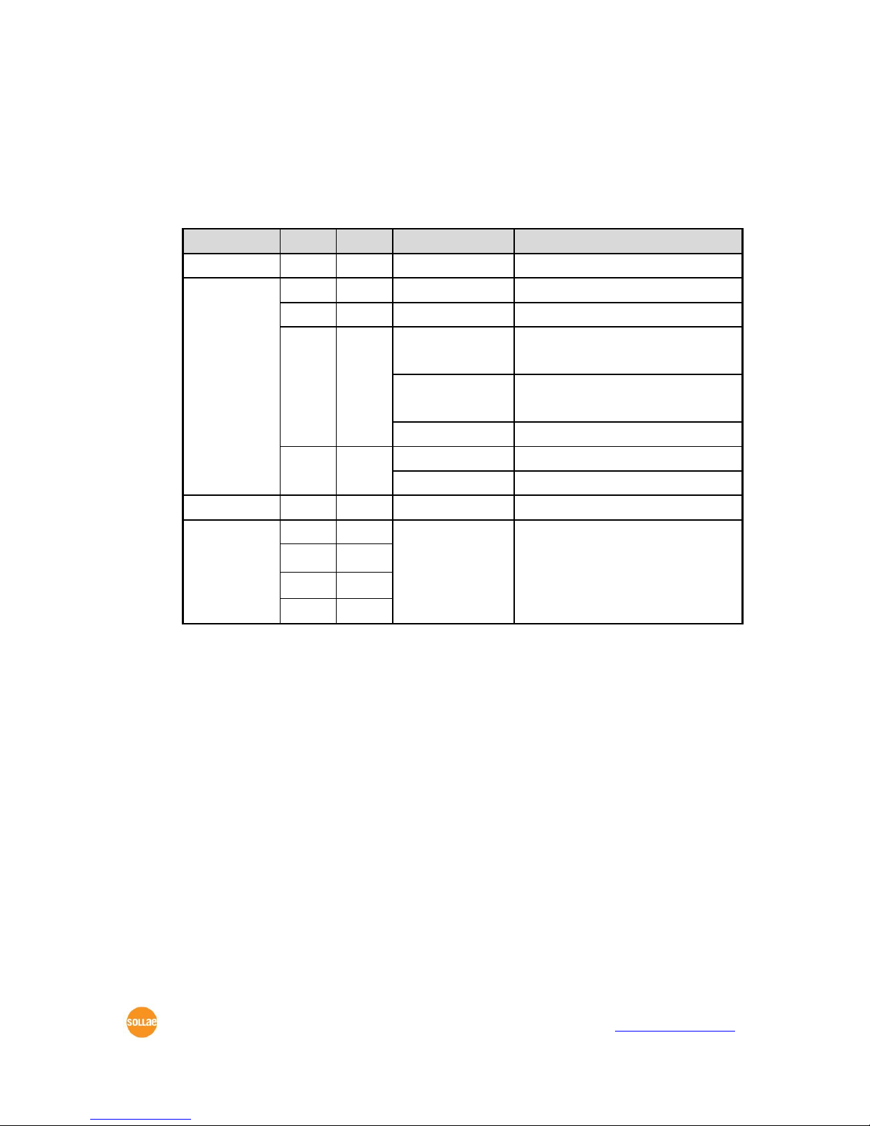
A situation that [Timeout] is set to 5
Figure 5-3 time chart
Time
States
~
Data communication on both sides
①
The last segment arrives at the CSW-H85F
~
No data communication for 5 seconds
②
CSW-H85F sends disconnection request (FIN) to a remote
host
~
Processes of the disconnection
③
The connection is terminated
~
CSW-H85F listens connection requests
Table 5-4 states of each point

CSW-H85F User’s Manual Ver. 1.3
Sollae Systems Co., Ltd.
- 39 -
http://www.ezTCP.com
5.2 TCP Client
In this mode, CSW-H85F sends request segments to a TCP server with information of
[Peer Address] and [Peer Port]. Once a host is listening, the connection will be established.
After then, CSW-H85F converts the raw data from the serial port to TCP/IP data and sends
them to the network and vice versa.
Key parameters 5.2.1
Peer Address
This item is an address of TCP server.
Peer Port
[Peer Port] is a port number of TCP server.
Event Byte
This item can decide the point of time to send the connection request parameter.
Value
The point of time to send request segment
0
right after CSW-H85F boots up
Otherwise
(512 or under)
right after the bytes set to [Event Byte] have been received from
the serial port
Setting to less than 512 bytes is strongly recommended.
Table 5-5 the operation of Event Byte 1
In addition, you can handle the serial data before a TCP connection is established
with this parameter.
Value
Description
0
CSW-H85F does not send the data
Otherwise
(512 or under)
CSW-H85F sends the data right after a connection is established.
Setting to less than 512 bytes is strongly recommended.
Table 5-6 the operation of Event Byte 2
Timeout
If there is no data transmission for amount of the time the connection would be
terminated.
TCP Server
This check option enables you to get to the TCP Server / Client mode. In this mode,
CSW-H85F can be operated as a TCP server or client without changing its settings.
DNS IP Address
[DNS IP Address] is needed when you use a host name instead of an IP address.

CSW-H85F User’s Manual Ver. 1.3
Sollae Systems Co., Ltd.
- 40 -
http://www.ezTCP.com
Examples 5.2.2
A situation that [Event Byte] is set to 0
Figure 5-4 time chart
Time
States
~
Power is not supplied yet.
①
CSW-H85F sends a connection request segment right after it
boots up.
~
processes of TCP connection
②
The connection is established.
~
data communication on both sides
Table 5-7 states of each point
Look at the blue arrow. The data “123” from the serial port was sent before establishing a
connection. In this case, the data would not be sent because of the [Event Byte] is set to 0.

CSW-H85F User’s Manual Ver. 1.3
Sollae Systems Co., Ltd.
- 41 -
http://www.ezTCP.com
A situation that [Event Byte] is set to 5
Figure 5-5 time chart
Time
States
~
CSW-H85F receives data from its serial port.
①
CSW-H85F sends a connection request segment right after receiving
5 bytes.
~
processes of the TCP connection
②
The connection is established.
~
The data “1234567” is transmitted to the remote host.
Table 5-8 states of each point
As you can see, CSW-H85F has sent a request segment right after the size of the serial
data has been 5 bytes. Even though they arrived before the connection, the data “123”, “45”
and “67” was transmitted to the remote host because the [Event Byte] is set to 5.

CSW-H85F User’s Manual Ver. 1.3
Sollae Systems Co., Ltd.
- 42 -
http://www.ezTCP.com
Activation of [TCP Server] option
Figure 5-6 time chart
Time
States
~
CSW-H85F listens to connection requests
①
The connection has been established
~
CSW-H85F is online and processes of the disconnection
②
The connection is terminated
~
Both sides are offline
③
Sends TCP connection request segment
Table 5-9 states of each point
The TCP Server / Client mode can be useful option by using [Event Byte] and [Timeout].
Note that only one TCP connection can be established at the same time, so users should
consider setting [Timeout] properly.

CSW-H85F User’s Manual Ver. 1.3
Sollae Systems Co., Ltd.
- 43 -
http://www.ezTCP.com
5.3 AT Command
In AT command mode, you can control CSW-H85F with AT commands like a controlling
modem. Active and passive TCP connections are available while UDP is not. And you are
allowed to configure some environmental parameters with extended commands.
Key parameters 5.3.1
The configuration should be implemented via the serial port.
Commands
Description
Examples
+PLIP
Local IP Address
at+plip=10.1.0.1<CR>
+PLP
Local Port
at+plp=1470<CR>
+PRIP
Peer IP Address
at+prip=10.1.0.2<CR>
+PRP
Peer Port
at+prp=1470<CR>
+PDC
DHCP
at+pdc=1<CR>
+PTO
Timeout
at+pto=10<CR>
+WCCT
WLAN Topology
at+wcct=1<CR>
+WSSID
SSID
at+wssid=”sollae”<CR>
+PWP
Store setting
at+pwp<CR>
Table 5-10 some of extended AT commands for configuration
Related items with an IP address and Local Port
Local port can be set as well as IP address related parameters like IP address, Subnet
Mask and Gateway IP address.
Peer Address / Peer Port
An IP address and local port of a remote host are can be set.
Type of assigning IP address: Manual, DHCP
Not only is manual setting available, but automatic assigning protocol (DHCP).
WLAN parameters
WLAN Topology, SSID and antenna can be configured by the above commands.
Others
Some of options including [Timeout] can be configured in this mode.
Refer to AT Command mode for more details.

CSW-H85F User’s Manual Ver. 1.3
Sollae Systems Co., Ltd.
- 44 -
http://www.ezTCP.com
Examples 5.3.2
TCP Server – setting parameters and passive connection
Figure 5-7 time chart
Time
States
~
configuring parameters with AT commands
①
ATA command has arrived.
~
CSW-H85F listens to TCP connection requests.
②
A remote host sends SYN segment to CSW-H85F.
~
processes of TCP connection
③
TCP connection is established.
~
CSW-H85F sends “CONNECT” message to the serial port.
Table 5-11 states of each point
Some of the response messages from the serial port of CSW-H85F are omitted on
above figure.
CSW-H85F User’s Manual Ver. 1.3
Sollae Systems Co., Ltd.
- 45 -
http://www.ezTCP.com
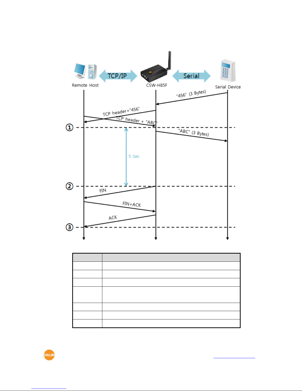
TCP Client – setting parameters and active connection
Figure 5-8 time chart
Time
States
~
configuring parameters with AT commands
①
CSW-H85F sends TCP connection request with the ATD command.
~
processes of TCP connection
②
TCP connection is established.
~
CSW-H85F sends “CONNECT” message to the serial port.
Table 5-12 states of each point

CSW-H85F User’s Manual Ver. 1.3
Sollae Systems Co., Ltd.
- 46 -
http://www.ezTCP.com
Termination of online status – entering the AT command mode
Figure 5-9 time chart
Time
States
~
TCP connection is on-line.
①
The mode is changed to “command mode” after receiving “+++”.
~
command mode (TCP connection is off-line)
②
CSW-H85F sends FIN segment right after the “ATH” arrives.
~
processes of TCP disconnection
③
TCP connection is terminated
~
CSW-H85F sends “NO CARRIER” with disconnection.
Table 5-13 states of each point
CSW-H85F changes the mode to AT command, when receiving “+++”. In this state, the
communication with remote host is unavailable because CSW-H85F processes only AT
commands. Whenever you want to go back to on-line state, just give “ATO” command.

CSW-H85F User’s Manual Ver. 1.3
Sollae Systems Co., Ltd.
- 47 -
http://www.ezTCP.com
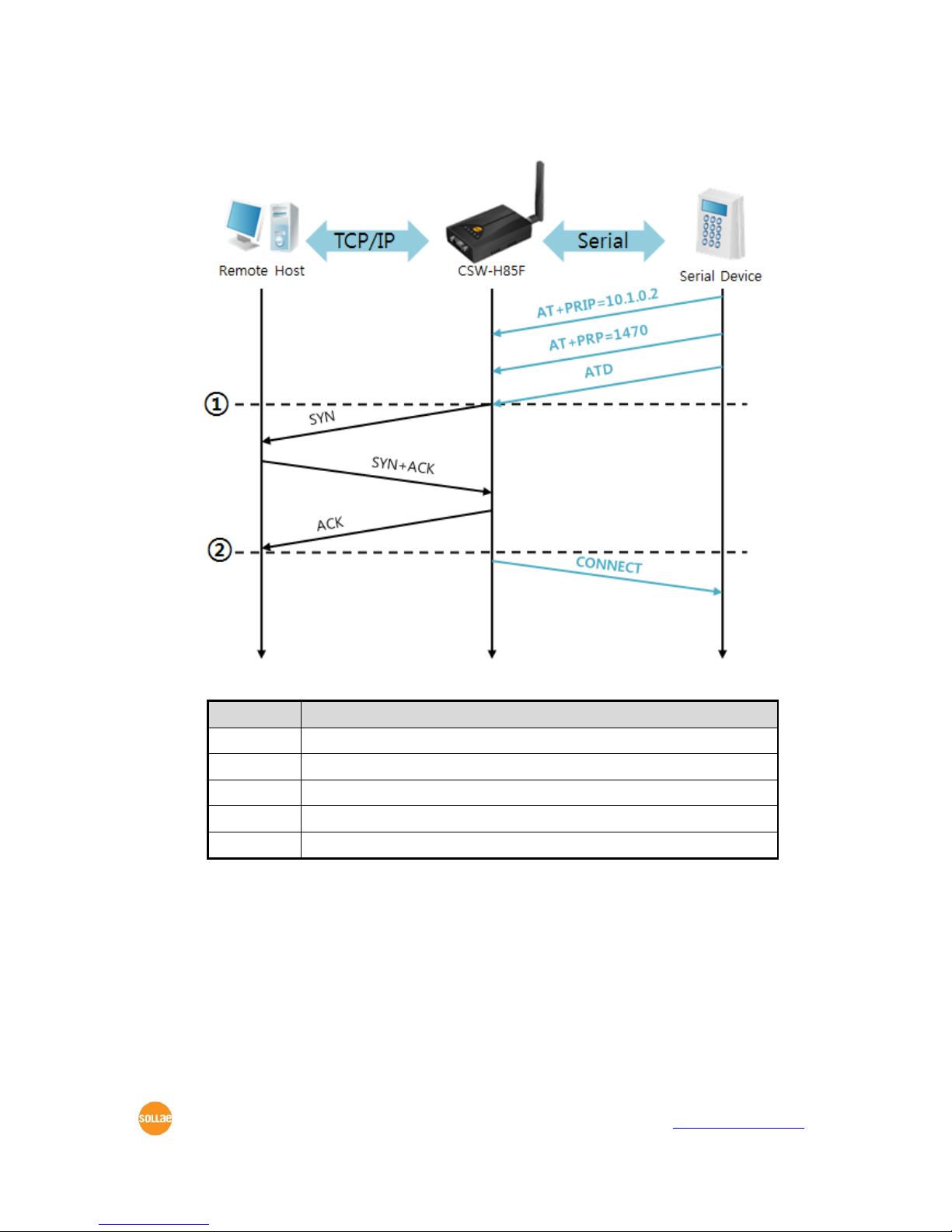
5.4 UDP
UDP has no connection processes. In this mode, data is sent in block units. Therefore,
data that comes through CSW-H85F’s serial port is collected in block units to send it
elsewhere.
Key parameters 5.4.1
Event Byte
[Event Byte] is to set the time to gather data in one block. Its unit is byte. If the data
in configured size of the [Event Byte] comes into the serial port, CSW-H85F will send
them as one block to the network. The maximum value could be 1460 bytes.
Data Frame
[Data Frame] means the time for gathering data to make one block. Its unit is 10ms.
If there is no data from the serial devices during the [Data Frame] time, CSW-H85F
sends and receives data in the buffer as one block to the network.
Once one of the two parameters, event byte and data frame, is sufficient, UDP
packet block will be transmitted.
Dynamic update of Peer host
If you set the value of [Peer Address] and [Peer Port] to 0, [dynamic update of peer
host] function is activated. By using this function, CSW-H85F can communicate to
multiple hosts without additional setting.

CSW-H85F User’s Manual Ver. 1.3
Sollae Systems Co., Ltd.
- 48 -
http://www.ezTCP.com
Examples 5.4.2
Event Byte: 5 bytes / Data Frame: 1sec
Figure 5-10 time chart
Time
States
~
CSW-H85F receives data from the serial port
①
CSW-H85F sends 5 bytes as one block based on the [Event byte].
~
Serial device sends data “678”.
②
The data “678” arrives.
~
CSW-H85F sends data from the remote host to the serial device
③
1 second
~
CSW-H85F sends data “678” as one block based on the [Data frame].
Table 5-14 states of each point

CSW-H85F User’s Manual Ver. 1.3
Sollae Systems Co., Ltd.
- 49 -
http://www.ezTCP.com
Dynamic Update of Peer host
This is a function that CSW-H85F automatically sets its peer host with information of
the last packet received from network. The source address of the packet is set to the
peer host.
Parameters
Values
Peer Address
0 (None)
Peer Port
0
Table 5-15 setting for [dynamic update of peer host] function
Figure 5-11 time chart
Time
States
~
Sending any UDP data to the network is impossible.
①
UDP data arrives from Remote Host 2.
~
Send UDP data to Remote Host 2.
②
UDP data arrives from Remote Host 1.
~
Send UDP data to Remote Host 1.
③
UDP data arrives from Remote Host 2.
~
Send UDP data to Remote Host 2.
Table 5-16 states of each point
The data “ABC”, “DE” and “FGH” are ones that come from the serial port of CSWH85F in the above figure.

CSW-H85F User’s Manual Ver. 1.3
Sollae Systems Co., Ltd.
- 50 -
http://www.ezTCP.com
6 System Management
6.1 Upgrading Firmware
Firmware 6.1.1
Firmware is a type of software to operate CSW-H85F. If there are needs for adding
functions or fixing bugs, the firmware can be modified and released. That is why we always
recommend using the latest firmware.
Processes 6.1.2
Downloading the latest firmware
Download the latest firmware file uploaded at our website.
Connecting the serial ports
Connect the serial port of CSW-H85F to the PC’s COM port with RS232 cross cable.
Run Change F/W / HTML program for sending the F/W file
Run the program on ezManager and click the [Change F/W / HTML] button.
Figure 6-1 running Change F/W / HTML program for sending F/W file
① Press the [Open] button after selecting the COM port.
② Click the [Advanced Menu] check box.
③ Press the [Change F/W / HTML] button.
④ Check the [Change Firmware] radio button.
⑤ Press the [Open Firmware / HTML] button and choose the firmware file.

CSW-H85F User’s Manual Ver. 1.3
Sollae Systems Co., Ltd.
- 51 -
http://www.ezTCP.com
Checking firmware file and Sending
Figure 6-2 sending firmware file
① Check if the name and path of the firmware file are correct.
② Click the [Send] button.
③ Restart request will be shown. After rebooting, the program will send the file
automatically.
④ Confirm the completion message.

CSW-H85F User’s Manual Ver. 1.3
Sollae Systems Co., Ltd.
- 52 -
http://www.ezTCP.com
6.2 Status Monitoring
TELNET 6.2.1
When the [TELNET] option is activated, you can remotely log in to CSW-H85F. If a
password is set, you should input the password. After then, messages from CSW-H85F will
appear like the following figure.
Figure 6-3 log in to CSW-H85F via TELNET
The following commands help you check states of CSW-H85F
Command
Option
Description
Usage
st
net
IPv4 Network Status
lsh>st net
net6
IPv6 Network Status
lsh>st net6
sio
Serial Port Status
lsh>st sio
uptime
System Uptime
lsh>st uptime
sc
[OP1][OP2]
Session Close
lsh>sc com1 close
Table 6-1 commands for checking states
st net
This command is displays current IPv4 network states of all sessions.
Figure 6-4 “st net” command
st net6
This command displays current IPv6 network states of all sessions.
Figure 6-5 “st net6” command

CSW-H85F User’s Manual Ver. 1.3
Sollae Systems Co., Ltd.
- 53 -
http://www.ezTCP.com
st sio
This command is displays the number of bytes of the serial port.
Figure 6-6 “st sio” command
st uptime
This command displays system uptime since CSW-H85F has booted up.
Figure 6-7 “st uptime” command
sc
This command disconnects one of the current sessions. Input session name to [OP1]
and “close” command to [OP2].
Figure 6-8 “sc” command
You can download TCP Client application for a smartphone on our website.

CSW-H85F User’s Manual Ver. 1.3
Sollae Systems Co., Ltd.
- 54 -
http://www.ezTCP.com
Status Window of ezManager 6.2.2
Status of CSW-H85F can be monitored by the [Status] button on ezManager. By using the
[Refresh Every 1 Second] option in the window, the status will be automatically updated in
every second.
Figure 6-9 status window of ezManager
FIRMWARE VERSION
The name of model and the version of firmware are displayed here.
SYSTEM UPTIME
Amount of operating time since CSW-H85F has booted up is displayed.
IP4 NETWORK INFORMATION
All information about related items with the IPv4 Address is shown here.

CSW-H85F User’s Manual Ver. 1.3
Sollae Systems Co., Ltd.
- 55 -
http://www.ezTCP.com
IP6 NETWORK INFORMATION
All information about related items with the IPv6 Address is shown here. This item will
be shown only when IPv6 is enabled.
TCP STATE
TCP status of each port is shown in this section.
Message
Description
LISTEN
The session is waiting for TCP connection.
CLOSE
TCP connection is closed.
SYN_SENT
The session is sending “SYN” segment to a TCP server.
ESTABLISHED
TCP connection is established.
N/A
in UDP mode
Table 6-2 TCP STATE
Amount of data
Amount of data in each buffer is displayed. The unit is byte.
Buffer
Description
sio_rx
The number of data which is received from the COM port
net_tx
The number of data which is sent to the remote host
net_rx
The number of data which is received from the remote host
sio_tx
The number of data which is sent to the COM port
Table 6-3 SERIAL STATUS

CSW-H85F User’s Manual Ver. 1.3
Sollae Systems Co., Ltd.
- 56 -
http://www.ezTCP.com
ARP Table / ND Cache Table
This part shows ARP table on CSW-H85F. When TCP connection is established or UDP
data communication is performed, the information of IP and MAC address is
automatically registered in the table. This information lasts for 1 minute so when 50
seconds has passed, CSW-H85F starts broadcasting the ARP packet in every second. If
there is no response until the time is 0, the information is removed. Otherwise, the
time is updated 60 seconds again.
In IPv6 case, it shows ND cache table. User can check by the ND cache messages. The
messages are as follows.
State
Description
INCOMPLETE
This means the device is standing by after it sends the
request message, Neighbor Solicitation, to MAC and link
local address of an opponent in the initial communication.
REACHABLE
This means the device has information about the opponent
after it sends Neighbor Solicitation, and receives Neighbor
Advertisement.
STALE
The device will change into STALE state after some time later
reaching REACHABLE.
DELAY
The device will change into DELAY state if there is no
response to Neighbor Solicitation. In this case, CSW-H85F will
not be able to communicate with the device.
PROBE
CSW-H85F will resend the request message to the device in
DELAY state. CSW-H85F will keep sending Neighbor
Solicitation until it replies.
Table 6-4 5 states of ND cache table
Wi-Fi Status
Status of Wireless LAN Channel is displayed.
Item
Description
Channel
Current channel (Frequency band)
Link Speed
Maximum data rate of the link (Unit: Mbps)
RSSI
Received Signal Strength Indication (Unit: dBm)
RSNA
Current authentication algorithm (WEP, TKIP, CCPM)
Table 6-5 Wi-Fi status

CSW-H85F User’s Manual Ver. 1.3
Sollae Systems Co., Ltd.
- 57 -
http://www.ezTCP.com
TCP/IP Connection
The same information with [TCP STATE] is displayed with an IP address and port
number. A difference from [TCP STATE] is whether you can terminate TCP connection
or not. When right click on a session, a small window will be popped up.
Password
This text box is activated when CSW-H85F has a password. If you want to close TCP
connection on [TCP/IP Connection] list, input the password first.
Refresh Every 1 Second.
If this option is checked, ezManager sends queries in every second.
IP Address Conflict Detection
By clicking this button, you can find devices which have the same IP address to yours
on the network.
Figure 6-10 no confliction of IP addresses
Figure 6-11 confliction of IP addresses
CSW-H85F User’s Manual Ver. 1.3
Sollae Systems Co., Ltd.
- 58 -
http://www.ezTCP.com
7 Additional Functions
7.1 Security
Access Restriction (ezTCP Firewall) 7.1.1
On the [Option] tab of ezManager, you can set access restriction function with MAC and
IP address.
Allowed MAC Address
If this option has a valid value, the device which has the MAC address is only
permitted to access.
Allowed IP Address
This is for qualifying hosts with IP address or range of IP addresses. The range is
defined by multiplying [IP address] and [Network Mask] in bit unit.
Examples for IPv4
IP Address
Network Mask
Allowed IP Address Range
10.1.0.1
255.0.0.0
10.1.0.1 ∼ 10.255.255.254
10.1.0.1
255.255.255.0
10.1.0.1 ∼ 10.1.0.254
192.168.1.4
255.255.255.255
192.168.1.4
Table 7-1 examples of defining allowed IPv4 range
Apply to ezManager
[Apply to ezManager] is for applying above two restrictions to ezManager functions
like [Search], [Read], [Write] and etc.
Examples for IPv6
IPv6 Address
Prefix
Allowed IP Address Range
2001:DB8::100
64
2001:DB8::1 ~ 2001:DB8::FFFF:FFFF:FFFF:FFFF
2001:DB8::100
128
2001:DB8::100
Table 7-2 examples of defining allowed IPv6 range
Setting Password 7.1.2
A password can be used for protecting CSW-H85F from TELNET login or changing
environmental parameters by hosts which are not qualified. The maximum length is 8 bytes
of alphabet or number.

CSW-H85F User’s Manual Ver. 1.3
Sollae Systems Co., Ltd.
- 59 -
http://www.ezTCP.com
Using WEP 7.1.3
AP settings
Set parameters such as authentication mode(open / shared) and key length(64 / 128)
on your AP. If you do not know how to set AP’s parameters, refer to the manual or
ask the manufacturer.
CSW-H85F settings
Input WEP Key, which is set on the AP, in [Shared Key] text box of [Security Settings]
section on [WLAN] tab of ezManager.
Figure 7-1 Shared Key settings
Parameter
Available Values
Length
64 bits
128 bits
Type (ASCII code)
5-digits
13-digits
Table 7-3 WEP key settings
Using WPA-PSK 7.1.4
AP settings
Set the WPA-PSK or WPA2-PSK and related parameters on your AP. If you do not
know how to set AP’s parameters, refer to the manual or ask the manufacturer.
CSW-H85F settings
Input WPA-PSK Key, which is set on the AP, in [Shared Key] text box of [Security
Settings] section on [WLAN] tab of ezManager. (See the Figure 7-1 Shared Key
settings)
The length of Key for WPA-PSK should be 8 ~ 63 characters.

CSW-H85F User’s Manual Ver. 1.3
Sollae Systems Co., Ltd.
- 60 -
http://www.ezTCP.com
Using WPA-Enterprise 7.1.5
Configuration of the Access Point
Set the WPA-Enterprise for authentication and radius server to communicate. If you
do not know how to set AP’s parameters, refer to the manual or ask the manufacturer.
CSW-H85F supports EAP-TLS / TTLS and PEAP.
Configuration of the product
Select one of authentication protocols on 802.1X item in the Security Settings.
Protocol
required configurations
EAP-TLS
ID of radius server account, client certificate
EAP-TTLS
ID and passphrase of radius server account
PEAP
ID and passphrase of radius server account
Table 7-4 802.1X item
How to use EAP-TLS
In the case of EAP-TLS, a certificate is needed to save by ezManager.
The procedures are as follows:
① Configure the ID of radius server account
② Check the [Advanced Menu] option and click the [Certificate] button
Figure 7-2 Certificate button
③ Save the client certificate made by radius server
Figure 7-3 saving client certification
④ Input password for the certificate
⑤ Check the information of the certificate

CSW-H85F User’s Manual Ver. 1.3
Sollae Systems Co., Ltd.
- 61 -
http://www.ezTCP.com
Advanced Settings 7.1.6
You can configure advanced settings for WLAN with this button. We recommend using
the default values if you do not have any problem with it.
Figure 7-4 Advanced Settings
PHY Mode
You have three options for PHY mode and those are [802.11], [802.11b] and
[802.11b/g] mode.
Short Preamble
Under good condition of WLAN environment, you can expect a slight improvement
by enabling this option. Otherwise, you had batter to disable this option.
Short Slot
Using this option, you can expect some improvement in WLAN performances. If you
are in bad condition of WLAN environment, you had batter to disable this option.
CTS Protection
Using this option, you can expect some improvement in WLAN performances under
WLAN environment that both 802.11b and 11g devices are.

CSW-H85F User’s Manual Ver. 1.3
Sollae Systems Co., Ltd.
- 62 -
http://www.ezTCP.com
7.2 Option Tab Functions
Notify IPv4 Change 7.2.1
CSW-H85F can be a TCP server even though its IPv4 address is automatically assigned.
Using [Notify IP Change] function, CSW-H85F sends its IP address to the specific server. It is
offered in 3 types of services, DDNS, TCP and UDP.
Dynamic Domain Name Service (DDNS)
CSW-H85F supports DDNS service offered by DynDNS. Therefore, you have to make
an account and create host names at the DynDNS website before you use.
All about service usage of an account could be changed according to the policy of
DynDNS.
DynDNS website: http://dyn.com/dns/
Figure 7-5 setting DDNS
① Select the [DDNS(dyndns.org)].
② 40,320 is a fixed value.
③ Input the ID of DDNS account.
④ Input the password of the account.
⑤ Input a host name which you create on your account.
TCP/UDP
In case you have your own server and want to manage the information about
changed IP addresses, you are allowed to use TCP/UDP. Not only can you set the
[Interval], but also use both ASCII and hexadecimal in [Data Type].
Refer to the [IP Change Notification] document on our website for details.

CSW-H85F User’s Manual Ver. 1.3
Sollae Systems Co., Ltd.
- 63 -
http://www.ezTCP.com
Sending MAC Address 7.2.2
[Sending MAC Address] is a function that the CSW-H85F sends its MAC address to the
remote host right after a connection. By using this function, a server can identify multiple
devices with the information.
Figure 7-6 setting of Sending MAC Address function
① Click the [Option] tab.
② Check the [Send MAC Address] option.
Refer to the [Sending MAC Address Function] document on our website for details.

CSW-H85F User’s Manual Ver. 1.3
Sollae Systems Co., Ltd.
- 64 -
http://www.ezTCP.com
7.3 Serial Port Tab Functions
Figure 7-7 setting of TELNET COM Port Control option
TELNET COM port Control Option (RFC 2217) - ① 7.3.1
This option is for sending and receiving serial port states between two devices. You can
send and receive control signals such as RTS/CTS when the states are changed.
Refer to the [TELNET COM Port Control Option] document on our website for
details.
Disable TCP Transmission Delay - ② 7.3.2
If you use this option, CSW-H85F sends the data from the serial port to WLAN as quickly
as possible.

CSW-H85F User’s Manual Ver. 1.3
Sollae Systems Co., Ltd.
- 65 -
http://www.ezTCP.com
Data Frame Interval - ③ 7.3.3
Before sending data from the serial port to WLAN, CSW-H85F gathers data in the buffer.
If there is no data during the time configured in the [Data Frame Interval], it will send data
to the network. In case the value is set to 0, data will be sent immediately. The unit is 10ms
and this is operated more accurately by checking [Disable TCP Transmission Delay] option.
Setting this value to over 11 is recommended.
Separator - ④ 7.3.4
Using this function, you can control the length of network packets by specific characters.
separator
options
Length
select the length between 0 ~ 4 bytes
Operation
Transmit Separators without additional bytes
Transmit Separators + 1 byte
Transmit Separators + 2 bytes
Table 7-5 separator
TCP Server / Client mode - ⑤ 7.3.5
This mode is available on TCP client mode only. In this mode, you do not need to
change the mode for switching active or passive TCP connection. Note that the [Event Byte]
option should be set to more than 1.
Refer to the [TCP Server/Client mode] document on our website for details.

CSW-H85F User’s Manual Ver. 1.3
Sollae Systems Co., Ltd.
- 66 -
http://www.ezTCP.com
7.4 Additional Functions
Wireless RSSI(Received Signal Strengh Indication) function 7.4.1
CSW-H85F indicates 4 levels of Received Signal Strength Indication (RSSI), measured from
product side by LEDs.
Using Wireless RSSI function
Establishing a wireless network, locate the function switch to the right side (RUN).
Figure 7-8 setting of Wireless RSSI function
Using this function, CSW-H85F indicates the RSSI by using 4 LED indicators which are
listed on the table below.
Division
TXD
RXD
LINK
STS
RSSI < -70dBm
OFF
OFF
OFF
ON
-70dBm ≤ RSSI < -60dBm
OFF
OFF
ON
ON
-60dBm ≤ RSSI < -50dBm
OFF
ON
ON
ON
-50dBm ≤ RSSI
ON
ON
ON
ON
Table 7-6 4 states of Wireless RSSI function
Higher values of RSSI represent higher qualities of the wireless signal.

CSW-H85F User’s Manual Ver. 1.3
Sollae Systems Co., Ltd.
- 67 -
http://www.ezTCP.com
Factory Reset 7.4.2
It is a function physically initializes all the setting. You can save a setting to user-defined
ENV region and use it as default values by the factory reset. However, if you do not use the
region, Factory Reset uses a factory default by manufacturer as its default values.
Using Factory Reset
① Move the function switch to the left(SET).
Figure 7-9 setting of Serial Configuration mode
② Push the function button over 5 seconds.
③ Factory Reset will be automatically implemented to default values.
④ Move the function switch to the middle(RUN).
⑤ Reboot.
Setting custom default values
① Change the mode to Serial Configuration
② Save custom default values by ezManager or serial configuration commands
③ Input the command below
b
<SPACE>
3c5a
<CR>
④ After step ③, current values in the SRAM is saved in user-defined ENV region and
the values will be always used for Factory Reset.

CSW-H85F User’s Manual Ver. 1.3
Sollae Systems Co., Ltd.
- 68 -
http://www.ezTCP.com
8 Checklist in Trouble
When you are in trouble with CSW-H85F, make sure all the following first.
8.1 Searching problem with ezManager
Confirming configuration utility
CSW-H85F should be configured by ezManager.
Stopping Firewall operation
A firewall on personal computer or network can block broadcast packets. Stop all the
firewalls before searching CSW-H85F
Most of vaccine applications have firewall functions so it can cause some trouble
to search CSW-H85F. Stop these programs before searching.
Stable supply of the power
Check if the power is supplied continually.
Connection with the wireless network
Check if the wireless link is established. After confirming that the status of LINK LED is
ON, check the list of wireless LAN devices on the management page of the AP.
After booting up, it may take some time (a few seconds) to establish a wireless
link according to the network condition.
Connection with the network
Make sure that the network connection between the PC and AP. In this step, we
recommend you to connect the AP with your PC directly or in the same network hub.
Checking options of restriction
In case that access restriction is activated, the communication with ezManager would
be impossible. When you are in this situation, make CSW-H85F operate in the Serial
Configuration mode to revoke the restriction.

CSW-H85F User’s Manual Ver. 1.3
Sollae Systems Co., Ltd.
- 69 -
http://www.ezTCP.com
8.2 Connection Problem over TCP/IP
Connection with the wireless network
Check if the wireless link is fine.
Checking parameters related with TCP/IP
When CSW-H85F has a private IP address, an IP address of a PC and CSW-H85F
needs to be on the same network. Check if the IP address and local port number are
correct. In the case of a fixed IP address related items such as subnet mask, gateway
IP address and DNS IP address should be configured.
TCP Server side
TCP Client side
Local IP Address, Local Port, Subnet
Mask, Gateway IP Address, DNS IP
Address, DDNS option, and etc.
Local IP Address, Peer Address, Peer Port,
Subnet Mask, Gateway IP Address, DNS IP
Address, and etc.
Table 8-1 major parameters related with TCP/IP
PING Test
Confirm the connection over the network by PING test. If the CSW-H85F does not
send any reply from the request, check the network environment.
Network Firewall
In the case of networks which need strong security, the access may be denied by
their firewall. Under this circumstance, consult the network administrator to release
ports which will be used. (Ex: TCP 1470, UDP 50005)
Operation Mode
TCP connection will not be established when CSW-H85F is operating in the ISP or
Serial Configuration mode.
Communication Mode
To make TCP connection, both a server and client should exist. If there are only
servers or clients, TCP connection cannot be established.
ezTCP Firewall
When you set the ezTCP firewall with MAC and IP address, all hosts cannot be
reachable except for the hosts have the allowed MAC and IP address. Inactivate the
option or check the setting is correct for allowing specific hosts to access.

CSW-H85F User’s Manual Ver. 1.3
Sollae Systems Co., Ltd.
- 70 -
http://www.ezTCP.com
Checking the TCP status
Basically, TCP is a protocol connected one to one. Because of this, if a device is TCP
on-line state, other requests are denied. If you are in this situation, check the network
status by connecting on TELNET or using ezManager.
8.3 Data Communication Problem on the Serial Port
Connection of Pins
Check if the each connection of pins is right. Refer to the chapter 1.7.3 to find out
the pin assignment. In the case of using a cable, you should choose the right type of
cable which is suitable for the device.
You must connect the Ground pin to your device when using RS422 or RS485 as
well as RS232.
Setting parameters
Check if all the serial port parameters like Baud Rate, Data bit, Stop bit and Parity are
properly set.
Please contact us if you have any questions about above steps or our products.

CSW-H85F User’s Manual Ver. 1.3
Sollae Systems Co., Ltd.
- 71 -
http://www.ezTCP.com
9 Technical Support, Warranty, and Precaution
9.1 Technical Support
If you have any question regarding operation of the product, visit Customer Support FAQ
corner and the message board on Sollae Systems’ web site or send us an email at the
following address:
Website Address for Customer Support: http://www.eztcp.com/en/support/
E-mail: support@eztcp.com
9.2 Warranty
Refund 9.2.1
Upon the customer’s request to refund the product within two weeks after purchase,
Sollae Systems will refund the product.
Free Repair Services 9.2.2
For product failures occurring within two years after purchase, Sollae Systems provides
free repair services or exchange the product. However, if the product failure is due to
user’s fault, repair service fees will be charged or the product will be replaced at user’s
expense.
Charged Repair Services 9.2.3
For product failures occurring after the warranty period (two years) or resulting from
user’s fault, repair service fees will be charged and the product will be replaced at user’s
expense.

CSW-H85F User’s Manual Ver. 1.3
Sollae Systems Co., Ltd.
- 72 -
http://www.ezTCP.com
9.3 Precaution
Sollae Systems is not responsible for product failures occurring due to user’s
alternation of the product.
Specifications of the product are subject to change without prior notice for
performance improvement.
Sollae Systems does not guarantee successful operation of the product if the
product was used under conditions deviating from the product specifications.
Reverse engineering of firmware and applications provided by Sollae Systems is
prohibited.
Use of firmware and applications provided by Sollae Systems for purposes other
than those for which they were designed is prohibited.
Do not use the product in an extremely cold or hot place or in a place where
vibration is severe.
Do not use the product in an environment in which humidity is high or a lot of oil
exists.
Do not use the product where there is caustic or combustible gas.
Sollae Systems does not guarantee normal operation of the product under the
conditions a lot of noise exists.
Do not use the product for a purpose that requires exceptional quality and
reliability relating to user’s injuries or accidents – aerospace, aviation, health care,
nuclear power, transportation, and safety purposes.
Sollae Systems is not responsible for any accident or damage occurring while using
the product.

CSW-H85F User’s Manual Ver. 1.3
Sollae Systems Co., Ltd.
- 73 -
http://www.ezTCP.com
10 Revision History
Date
Version
Description
Author
2012.08.22
1.0
○ Initial release
Roy LEE
2012.09.26
1.1
○ Modify descriptions of 4.2. Changing modes
○ Modify descriptions of Factory Reset function
○ Correct some errors and expressions
Roy LEE
2012.10.25
1.2
○ Add a clause about serial port parameters
○ Add description of WEB configuration
○ Modify configuration of WEP and WPA-PSK
○ Modify some document styles
○ Correct some errors and expressions
Roy LEE
2013.02.26
1.3
○ Modify description of Soft AP function
○ Add an example of TCP Server / Client mode
○ Add a description about test condition for certificate.
○ Add descriptions of ND cache table
○ Add a figure of IP address confliction
○ Modify descriptions of RS422/485 pin assignment
○ Add a description about connecting ground pins
○ Update some figures
○ Add a notification about mobile applications
○ Correct some errors and expressions
Roy LEE
 Loading...