


Sollae Systems Co., Ltd.
https://www.ezTCP.com
Serial Device Server
CSE-M32 User Manual
Version 3.2

CSE-M32 User Manual Ver. 3.2
Sollae Systems Co., Ltd. - 1 - https://www.ezTCP.com
This symbol, found on your product or on its packaging, indicates that this
product should not be treated as household waste when you wish to dispose
of it. Instead, it should be handed over to an applicable collection point for the
recycling of electrical and electronic equipment. By ensuring this product is
disposed of correctly, you will help prevent potential negative consequences to the
environment and human health, which could otherwise be caused by inappropriate disposal
of this product. The recycling of materials will help to conserve natural resources. For more
detailed information about the recycling of this product, please contact your local city
office, household waste disposal service or the retail store where you purchased this
product.
※ This equipment obtained certification by using 1.5M serial cable.

CSE-M32 User Manual Ver. 3.2
Sollae Systems Co., Ltd. - 2 - https://www.ezTCP.com
Contents
Contents ............................................................................................................................................ - 2 -
1 Overview .................................................................................................................................. - 6 -
1.1 Overview ................................................................................................................................................................ - 6 -
2 Specifications .......................................................................................................................... - 7 -
2.1 Components ......................................................................................................................................................... - 7 -
2.2 Specifications ....................................................................................................................................................... - 7 -
2.3 Interface ................................................................................................................................................................. - 8 -
2.3.1 Dimension .................................................................................................................................................... - 8 -
2.3.2 JP1 .................................................................................................................................................................... - 8 -
2.3.3 JP2 .................................................................................................................................................................... - 9 -
2.3.4 DC Electric Characteristics ................................................................................................................. - 10 -
2.4 Serial Interface.................................................................................................................................................. - 10 -
2.4.1 Serial Type ................................................................................................................................................. - 10 -
2.4.2 Serial Baud rate ...................................................................................................................................... - 10 -
2.4.3 Data bits, Parity, and Stop bit .......................................................................................................... - 11 -
2.4.4 Flow Control ............................................................................................................................................. - 11 -
2.4.5 Telnet COM Port Control Option (RFC2217)............................................................................. - 11 -
2.4.6 Disable TCP Transmission Delay ..................................................................................................... - 11 -
2.4.7 TX interval ................................................................................................................................................. - 11 -
2.4.8 TCP Server / Client mode .................................................................................................................. - 12 -
2.4.9 SPI Interface ............................................................................................................................................. - 12 -
2.5 Ethernet Interface ........................................................................................................................................... - 12 -
2.6 Application Circuits ........................................................................................................................................ - 12 -
2.6.1 RJ45 .............................................................................................................................................................. - 12 -
2.6.2 Application circuit ..................................................................................................................................... - 0 -
3 Test Run .................................................................................................................................... - 0 -
3.1 Test Run .................................................................................................................................................................. - 0 -
3.1.1 Changing PC IP Address ....................................................................................................................... - 0 -
3.1.2 Installing CSE-M32 ................................................................................................................................... - 0 -
3.1.3 Configuring CSE-M32 ............................................................................................................................. - 0 -
3.1.4 Communication Test ................................................................................................................................ - 1 -
4 Configuring IP Address and Variables................................................................................ - 4 -
4.1 IP Address and Environmental Variables ................................................................................................ - 4 -

CSE-M32 User Manual Ver. 3.2
Sollae Systems Co., Ltd. - 3 - https://www.ezTCP.com
4.2 Configuration with ezManager .................................................................................................................... - 4 -
4.2.1 ezManager ................................................................................................................................................... - 4 -
4.2.2 Buttons of ezManager ............................................................................................................................ - 5 -
4.2.3 Parameters of ezManager ..................................................................................................................... - 5 -
4.2.4 Matters to be attended to ................................................................................................................... - 6 -
4.3 AT command ........................................................................................................................................................ - 6 -
4.4 Notify IP Change ................................................................................................................................................ - 6 -
4.4.1 DDNS (Dynamic Domain Name System) ....................................................................................... - 6 -
4.4.2 TCP/UDP........................................................................................................................................................ - 7 -
5 Operation Mode ..................................................................................................................... - 8 -
5.1 Operation Mode Overview ............................................................................................................................ - 8 -
5.1.1 Overview ....................................................................................................................................................... - 8 -
5.2 How to Initiate Each Operation Mode .................................................................................................... - 8 -
5.2.1 Normal Mode ............................................................................................................................................. - 8 -
5.2.2 How to Initiate the Serial Configuration Mode ......................................................................... - 8 -
5.2.3 How to Initiate the ISP Mode ............................................................................................................. - 8 -
5.2.4 Comparison of Operation Modes ..................................................................................................... - 8 -
5.3 Normal Communication Mode ................................................................................................................... - 9 -
5.4 Serial Configuration Mode ............................................................................................................................ - 9 -
5.5 ISP Mode ............................................................................................................................................................ - 10 -
5.5.1 Upgrading Firmware............................................................................................................................. - 10 -
6 Normal Communication Mode ......................................................................................... - 11 -
6.1 T2S – TCP Server ............................................................................................................................................. - 11 -
6.1.1 TCP Connection ...................................................................................................................................... - 11 -
6.1.2 Serial Data before the TCP Connection ...................................................................................... - 11 -
6.1.3 Data Transmission ................................................................................................................................. - 11 -
6.1.4 Disconnection .......................................................................................................................................... - 12 -
6.2 COD – TCP Client ............................................................................................................................................ - 12 -
6.2.1 Serial Data before the TCP Connection ...................................................................................... - 12 -
6.2.2 Data Transmission ................................................................................................................................. - 13 -
6.2.3 Disconnection .......................................................................................................................................... - 13 -
6.2.4 DNS .............................................................................................................................................................. - 13 -
6.3 ATC ......................................................................................................................................................................... - 14 -
6.3.1 Key parameters ....................................................................................................................................... - 14 -
6.3.2 Examples .................................................................................................................................................... - 15 -
6.4 UDP ....................................................................................................................................................................... - 18 -
6.4.1 Key parameters ....................................................................................................................................... - 18 -

CSE-M32 User Manual Ver. 3.2
Sollae Systems Co., Ltd. - 4 - https://www.ezTCP.com
6.4.2 Examples .................................................................................................................................................... - 19 -
7 Security Protocols & Option ............................................................................................. - 21 -
7.1 SSL ......................................................................................................................................................................... - 21 -
7.1.1 SSL (Secure Socket Layer) .................................................................................................................. - 21 -
7.1.2 How to set the SSL on CSE-M32 ................................................................................................... - 21 -
7.1.3 Restriction.................................................................................................................................................. - 22 -
7.2 SSH ........................................................................................................................................................................ - 22 -
7.2.1 SSH (Secure Shell) ................................................................................................................................. - 22 -
7.2.2 How to set the SSH on CSE-M32 .................................................................................................. - 22 -
7.2.3 Restriction.................................................................................................................................................. - 23 -
7.3 ezTCP Firewall ................................................................................................................................................... - 23 -
8 Checking & Debugging ...................................................................................................... - 25 -
8.1 Telnet .................................................................................................................................................................... - 25 -
8.1.1 Telnet Login .............................................................................................................................................. - 25 -
8.1.2 Commands ................................................................................................................................................ - 25 -
8.2 Status on ezManager .................................................................................................................................... - 27 -
8.2.1 Status of the CSE-M32 ........................................................................................................................ - 27 -
8.2.2 Closing TCP connection by the ezManager .............................................................................. - 27 -
8.3 Remote Debugging ........................................................................................................................................ - 28 -
9 The Evaluation Board .......................................................................................................... - 29 -
9.1 Introduction ....................................................................................................................................................... - 29 -
9.2 Connectors ......................................................................................................................................................... - 29 -
9.3 Jumpers and Switches .................................................................................................................................. - 30 -
9.3.1 JP5 ................................................................................................................................................................. - 30 -
9.3.2 JP9, JP10..................................................................................................................................................... - 30 -
9.3.3 Reset Switch (S1) .................................................................................................................................... - 30 -
9.4 System LEDs classified each mode ......................................................................................................... - 31 -
9.5 Schematic of the evaluation board ........................................................................................................... - 0 -
10 Related material ...................................................................................................................... - 0 -
10.1 Technical Documents ....................................................................................................................................... - 0 -
10.2 Smart phone application ................................................................................................................................ - 0 -
11 Technical Support and Warranty ......................................................................................... - 1 -
11.1 Technical Support .............................................................................................................................................. - 1 -
11.2 Warranty ................................................................................................................................................................. - 1 -
11.2.1 Refund ............................................................................................................................................................ - 1 -

CSE-M32 User Manual Ver. 3.2
Sollae Systems Co., Ltd. - 5 - https://www.ezTCP.com
11.2.2 Free Repair Services ................................................................................................................................ - 1 -
11.2.3 Charged Repair Services........................................................................................................................ - 1 -
12 Precaution and Exemption from Liability .......................................................................... - 2 -
12.1 Precaution.............................................................................................................................................................. - 2 -
12.2 Exemption from Liability ................................................................................................................................. - 3 -
12.2.1 English version ........................................................................................................................................... - 3 -
12.2.2 French version ............................................................................................................................................ - 3 -
13 Revision History ...................................................................................................................... - 6 -

CSE-M32 User Manual Ver. 3.2
Sollae Systems Co., Ltd. - 6 - https://www.ezTCP.com
1 Overview
1.1 Overview
Along with the development of the Internet, the demand for data communication
functions has increased recently. Data communication over the Internet requires using
TCP/IP, the Internet communication protocol. That is to say, in order to connect a system to
the Internet, TCP/IP protocol must be implemented. It is possible to implement TCP/IP by
directly implementing the protocol, porting open TCP/IP in public or using Operating
System (OS). However, all these methods impose burdens on the developer in time, cost,
and technology.
ezTCP series, a Serial ↔ TCP/IP protocol converter product group of Sollae Systems,
enables you to use TCP/IP communication (the Internet communication) function simply by
“connecting the cable to a serial port”. ezTCP sends data from the serial port to the Internet
network after TCP/IP processing, and vice versa.
CSE-M32 in ezTCP product group is a product that provides TCP/IP communication
through Ethernet. In other words, like other ezTCP products, CSE-M32 sends data from the
serial ports to the LAN after TCP/IP processing and vice versa.
As CSE-M32 has 2 UART ports so that it supplies TCP/IP functions to two UART devices.
And because one UART port support the TCP speed of about 1.8Mbps, CSE-M32 is very
useful for the high speed communication device.
It provides DHCP and PPPoE functions, so that it can be applied to the cable network
and the xDSL network. And it has DDNS (Dynamic DNS) function, so it can be used more
easily in the internet.
It also provides debugging function, so user can solve the problem with ours.
CSE-M32 User Manual Ver. 3.2
Sollae Systems Co., Ltd. - 7 - https://www.ezTCP.com
2 Specifications
2.1 Components
⚫ CSE-M32 Body
⚫ Evaluation Board (Optional)
⚫ 5V SMPS Adapter (Optional)
⚫ RS232C cable for PC connection – DB9F-DB9M-2M (Optional)
2.2 Specifications
Power
Input Voltage
3.3V (±10%)
Current
230mA typical
Dimension
50mm x 32mm x 9mm
Weight
About 9g
Serial Port
2 x UART, 3.3V level with 5V tolerant input
300bps ~ 1843200bps
(COM2 port is disabled when COM1 is 1843200bps)
RTS/CTS flow control
Network
Ethernet 10Base-T or 100Base-TX (Auto-Sensing)
Auto MDI/MDIX
Protocols
TCP, UDP, IP, ICMP, ARP, DHCP, PPPoE, Telnet, DNS Lookup,
DDNS, Telnet COM Port Control Option(RFC2217), SSL, SSH
Diagnostic
Online Debugging Function
Temperature
Operating: 0 ~ 55℃, Storage: -40 ~ 85℃
RoHS
RoHS Compliant
Communicat
ion Mode
T2S
TCP Server Mode
COD
TCP Client Mode
ATC
TCP Server/Client
(AT command emulation)
U2S
UDP
Utilities
ezManager
Configuration utility via LAN
ezterm
Socket test utility
hotflash
Firmware download utility via TFTP
ezVSP
Serial-TCP/IP virtual driver for Windows

CSE-M32 User Manual Ver. 3.2
Sollae Systems Co., Ltd. - 8 - https://www.ezTCP.com
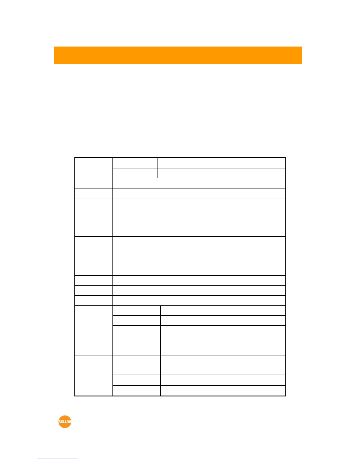
2.3 Interface
2.3.1 Dimension
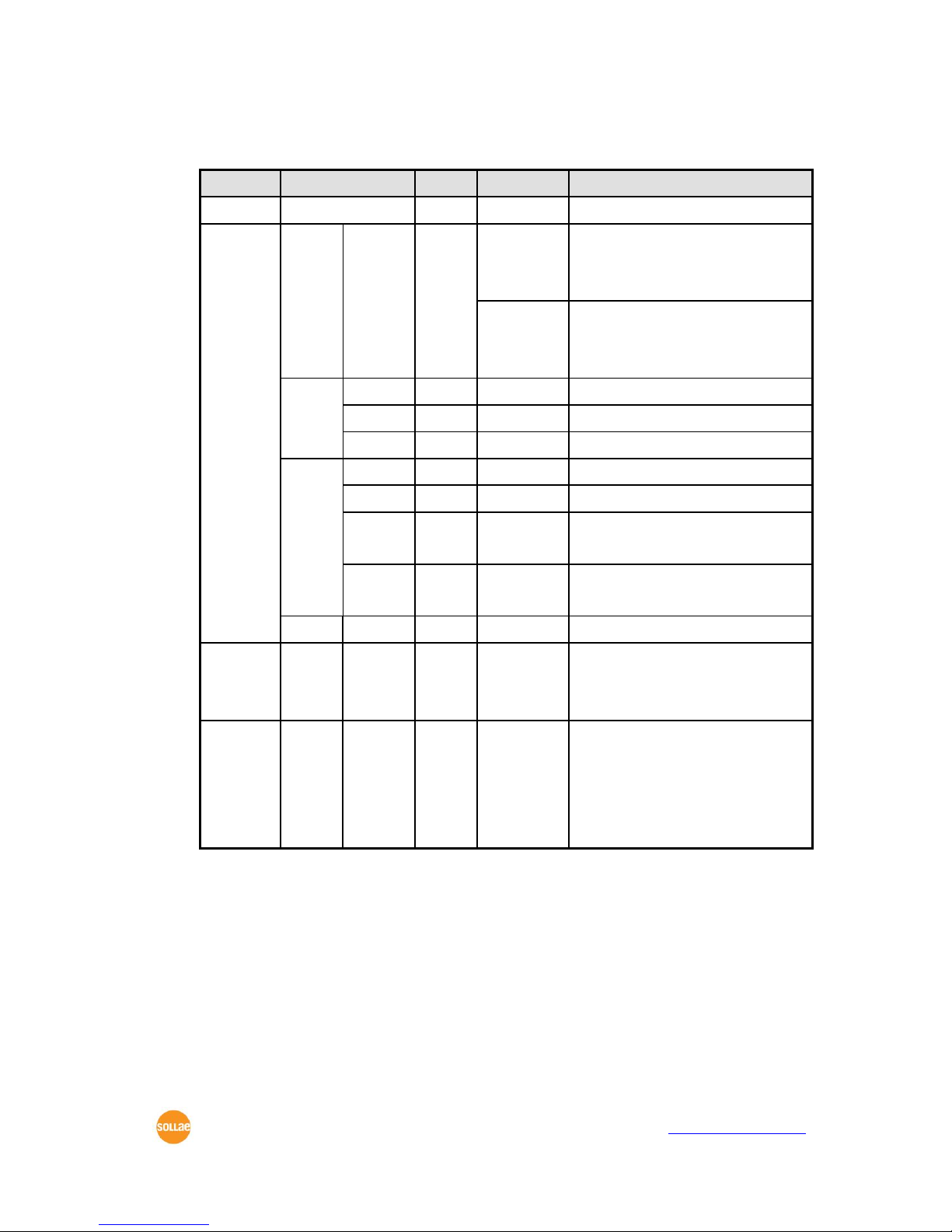
2.3.2 JP1
M: Mandatory
O: Optional
JP1
name
description
Dir.
Etc.
1
GND
Ground
-
M
2
TP_IN-
Ethernet In-
In
M
3
TP_IN+
Ethernet In+
In
M
4
PWFBOUT
PWFBOUT
In M 5
TP_OUT-
Ethernet Out-
Out M 6
TP_OUT+
Ethernet Out+
Out M 7
GND
Ground
-
M
8
LAN_RXD-
LAN RXD LED-
Blink: There are data on Ethernet line
Out O 9
LAN_TXD-
LAN TXD LED-
Blink: CSE-M32 transmits data to Ethernet port
Out O 10
LINK-
Link LED-
CSE-M32 is being connected to a LAN
Out
O
11
STS-
Status LED-
Out
O
12
VCC_33
VCC 3.3V
-
M
#1
#1
#2
CSE-M32 User Manual Ver. 3.2
Sollae Systems Co., Ltd. - 9 - https://www.ezTCP.com
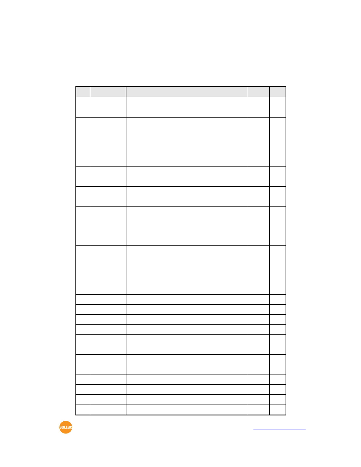
2.3.3 JP2
M: Mandatory
O: Optional
X: Don’t Connect
JP2
name
description
Dir.
Etc. 1 GND
Ground
- M 2
VCC_33
VCC 3.3V
-
M
3
SPI_NSS
SPI NSS
SPI Chip Select
In
N/A
4
SYS_RST-
Reset-
In/Out
O
5
SPI_MISO
SPI MISO
(Master In Slave Out)
Out
N/A 6 CN0-
TCP Connection 0 Status-
Low–UART0’s TCP connection is established
Out
O 7 SPI_MOSI
SPI MOSI
(Master Out Slave In)
In
N/A 8 CN1-
TCP Connection 1 Status-
Low–UART1’s TCP connection is established
Out
O
9
SPI_SCK
SPI SCK
SPI Serial clock
In
N/A
10
ISP-
ISP-
If this pin is low when it boots up, it
operates as ISP Mode (internally pulled-up).
If this pin is low for 20ms~1000ms, CSE-M32
enters to the serial configure mode.
In
O
11
GND
Ground
- M 12
GND
Ground
- M 13
UART_TXD1
UART1 (COM2)Transmitting Port
Out
O
14
UART_TXD0
UART0 (COM1) Transmitting Port
Out
O
15
UART_RTS1
UART1 (COM2) RTS
UART1 (COM2) TXDE (RS485 Mode)
Out
O
16
UART_RTS0
UART0 (COM1) RTS
UART0 (COM1) TXDE (RS485 Mode)
Out
O
17
DTXD
Port for factory
Out
X
18
GND
Ground
- M 19
UART_RXD1
UART1 (COM2) Receiving Port
In O 20
UART_RXD0
UART0 (COM1) Receiving Port
In
O

CSE-M32 User Manual Ver. 3.2
Sollae Systems Co., Ltd. - 10 - https://www.ezTCP.com
21
UART_CTS1
UART1 (COM2) CTS
In O 22
UART_CTS0
UART0 (COM1) CTS
In O 23
DRXD
Port for factory
In X 24
GND
Ground
-
M
2.3.4 DC Electric Characteristics
The followings are the DC electric Characteristics of the each pin.
Symbol
Min
Max
Unit
VIL
-0.3
0.8 V VIH
2.0
5.5
V
VOL
0.4
V
VOH
VCC_33 – 0.4
V
2.4 Serial Interface
There are two serial ports in CSE-M32. Each port can be configured independently.
2.4.1 Serial Type
User can set RS232, RS422 and RS485 to CSE-M32’s serial port. If CSE-M32 is configured
as RS485, the RTS pin operates as TXDE for RS485 line driver. (The TXDE is Low when CSEM32 doesn’t send data to its serial port and High when CSE-M32 sends data to its serial
port.)
2.4.2 Serial Baud rate
The following is configurable Baud rate table.
COM1
COM2
Etc.
300
300 600
600 1200
1200
2400
2400
4800
4800
9600
9600
14400
14400
19200
19200
38400
38400
57600
57600

CSE-M32 User Manual Ver. 3.2
Sollae Systems Co., Ltd. - 11 - https://www.ezTCP.com
115200
115200
230400
230400
460800
460800
921600
921600
1843200
-
If COM1 is set as 1843200, COM2 is disabled.
The maximum Baud rate of COM1 is 1,843,200bsp, and the maximum Baud rate of COM2
is 921,600bps. If COM1 is set as 1,843,200bps (its maximum Baud rate), the COM2 port is
disabled. (unavailable)
2.4.3 Data bits, Parity, and Stop bit
Item
Configurable Value
Data bit
8, 7, 6, 5
Parity
None, Even, Odd, Mark, Space
Stop bit
1, 1.5, 2
2.4.4 Flow Control
CSE-M32 support RTS/CTS Hardware Flow Control. RTS pin is for notifying connected
serial devices that its buffer can be available to receive data. CTS pin is for checking that
the RTS signal of its counterpart. To use this control CSE-M32 should be set to the type of
serial communication is RS232.
2.4.5 Telnet COM Port Control Option (RFC2217)
CSE-M32 has Telnet COM Port Control Option function that is specified by RFC2217. If
the Telnet COM Port Control Option is enabled, CSE-M32 sends the CTS control signal to
the communication counterpart, and CSE-M32 sets its serial port items (RTS, baud rate,
data bits, parity, stop bit) after getting information from the communication counterpart.
2.4.6 Disable TCP Transmission Delay
If you use this option, CSE-M32 sends the data from the serial port to Ethernet as quickly
as possible.
2.4.7 TX interval
This option is for preventing data loss in the case that the serial device has very small
buffer size or doesn’t have a buffer. The range of the value could be from 0 to 25 and the
unit is duration of sending 1 byte. For example, if you set this value to 5, each byte will be
transferred with duration of sending 5 bytes.

CSE-M32 User Manual Ver. 3.2
Sollae Systems Co., Ltd. - 12 - https://www.ezTCP.com
2.4.8 TCP Server / Client mode
This mode is available on TCP client mode only. In this mode, you don’t need to change
the mode for switching active or passive TCP connection. Note that the [Event Byte] option
should be set to 1 or lager value.
2.4.9 SPI Interface
CSE-M32 doesn’t support SPI interface.
2.5 Ethernet Interface
The Ethernet port has 10M/100M auto sense function and auto MDI/MDIX function. User
has to add additional circuit (a pulse-transformer and a RJ45) for Ethernet. Refer to the
following Application Circuits that we recommend you.
2.6 Application Circuits
2.6.1 RJ45
The RJ45 connector in this circuit embeds a pulse-transformer.
The followings are the recommended lists.
Part
Manufacturer
Description
RDA-126BAG1A
(old: RD1-126BAG1A)
UDE
With LEDs
RDA-106BAG1A
(old: RD1-106BAG1A)
UDE
Without LEDs
LU1S041XLF
Both hand
Without LEDs

2.6.2 Application circuit

3 Test Run
3.1 Test Run
You can perform test run according to the following orders. The test run described here
is based on the assumption that the IP address of the PC is set to 10.1.0.2
3.1.1 Changing PC IP Address
You can change the IP address of your PC as follows:
IP Address
10.1.0.2
Subnet Mask
255.0.0.0
Gateway IP Address
-
3.1.2 Installing CSE-M32
Insert the CSE-M32 to its evaluation board. Connect the offered RS232 cable (RJ45-DB9F1M) between your PC and the evaluation board, the LAN cable to the hub which the PC is
connected or directly to the PC, and the connect the power adapter to CSE-M32 evaluation
board inserting electric outlet for power supply. If the LAN cable has been correctly
connected when power is supplied, LINK LED will be turned on.
3.1.3 Configuring CSE-M32
Configure CSE-M32 setting using ezManager, the ezTCP configuration program, as
follows.
Run ezManager, and click [Search All] button in the ezManager window. And, ezManager
program will search all ezTCP including CSE-M32 on the local network.
When CSE-M32 is found, MAC address of the ezTCP is displayed on the [Search Results]
window (The MAC address is indicated on the body).
Select the corresponding MAC address, and set the variables considering your network
environment.
When no ezTCP is found, check the Windows firewall. If you press [Windows Firewall]
button in the ezManager, you can see the Windows Firewall menu directly.

CSE-M32 User Manual Ver. 3.2
Sollae Systems Co., Ltd. - 1 - https://www.ezTCP.com
For simple test, we recommend that the variables keep default values as shown in the
below table.
Parameter
Value
Network
Local IP Address
10.1.0.1
Subnet Mask
255.0.0.0
Option
Telnet
Enabled
IP Address Search
Enabled
Serial Port
(COM1/2)
Serial Type
RS232
Baud Rate
19200bps
Parity
NONE
Data Bits
8
Stop Bit
1
Flow
NONE
Communication Mode
T2S – TCP Server
Local Port
1470/1471
3.1.4 Communication Test
Power the CSE-M32 off and on, then it tries to connect to the LAN.
⚫ A program for testing starts if you press the [Simple Test] button of the ezManager.

CSE-M32 User Manual Ver. 3.2
Sollae Systems Co., Ltd. - 2 - https://www.ezTCP.com
⚫ Press the [Connect] button after inputting 10.1.0.1 and 1470 in the IP and Port. If
the TCP connection is established there will be “Connected [ 10.1.0.1 : 1470 ]. And
the STS indicator will be on.
⚫ Press the [Open] button after selecting serial port that is connected to the CSE-
M32. If the serial port is open, the “COM1 the COM port has opened” message will
be shown.

CSE-M32 User Manual Ver. 3.2
Sollae Systems Co., Ltd. - 3 - https://www.ezTCP.com
⚫ If you press the [Send Data] button on the LAN part (Top), the data shown in the
[Send] box will be transmitted to the [Receive] box on the RS232 part (Bottom).
⚫ If you press the [Send Data] button on the RS232 part (Bottom), the data shown in
the [Send] box will be transmitted to the [Receive] box on the LAN part.
⚫ If the transmitting and receiving data are same, the communication test is
successful.

CSE-M32 User Manual Ver. 3.2
Sollae Systems Co., Ltd. - 4 - https://www.ezTCP.com
4 Configuring IP Address and Variables
4.1 IP Address and Environmental Variables
For TCP/IP communication, you must set IP address related items. In addition, you have
to set serial port related items (serial port type, communication speed, data bit length,
parity bit, flow control, etc) to CSE-M32.
You can set the IP address and the serial port related items by using ezManager, the
supplied configuration utility which allows you to configure your CSE-M32 over the network,
or by using AT commands in ATC mode.
4.2 Configuration with ezManager
4.2.1 ezManager
The basic environmental variables (IP address related items, serial port items, and etc.)
can be set by ezManager which is an integrated management tool for Windows.
ezManager is operated in Microsoft Windows(Windows 2000 Pro, ME, XP Pro/Home,
Vista, 7). Following is the screen shot of ezManager which is just launched.
ezManager communicates UDP broadcast and its UDP ports are 50005 and
50006. Port number 50005 is for setting and port number 50006 is for debugging.
If you use any firewall function, the ports have to be opened.
CSE-M32 User Manual Ver. 3.2
Sollae Systems Co., Ltd. - 5 - https://www.ezTCP.com
4.2.2 Buttons of ezManager
Button
Description
Read
Read the values configured through MAC or IP address.
Write
Store the changed values of parameters
Set Password
Set or remove the password by this button.
Status
Check the status of ezTCP in real time.
Factory Reset
Initialize all the values as a default.
Debugging Message
Make the ezTCP broadcast debugging messages.
Change F/W / HTML
Change the firmware or HTML files with this button.
Export Variables
Store a set of values as a file.
Import Variables
Load values from a file made from [Export Variables]
Multi Write
Configure a set of values to one or more ezTCP
PING/ARP
Test the PING reply and manage the ARP table.
Simple Test
Run the test program interfaced with Network and RS232 port.
Windows Firewall
Run the windows firewall set window.
Exit
Exit ezManager
4.2.3 Parameters of ezManager
Tap
Section
Parameters
Network
Network
Local IP Address, Subnet Mask,
Gateway IP, DNS IP Address
Notify IP Change
Protocol, Interval, Port, Data Type, DDNS ID, DDNS
Password, Host Name(dyndns/custom)
Option
Obtain an IP From The First Received Packet,
Obtain an IP Automatically (DHCP),
Obtain an IP Automatically (PPPoE),
PPPoE ID, PPPoE Password,
Obtain DNS Server Address Automatically
Option
Option
Telnet, IP Address Search, Send MAC Address,
Debugging Message, SSL, SSH,
Multiple Connection
ezTCP Firewall
Allowed MAC Address, Allowed IP Range,
IP Address, Network Mask,
Apply To ezManager
Serial Port
Serial Port
Serial Type, TTL, Baud Rate, Parity, Data Bits, Stop
Bit, Flow Control, DTR/DSR, TX Interval

CSE-M32 User Manual Ver. 3.2
Sollae Systems Co., Ltd. - 6 - https://www.ezTCP.com
TCP/IP
Communication Mode, Peer Address,
Peer Port, Local Port, Event Byte, Timeout,
Data Frame
4.2.4 Matters to be attended to
ezManager can be used when you want to change your device’s environment variables.
In case of CSE-M32, two interfaces are supported and those are Ethernet and RS232 port.
⚫ Using Ethernet Port
For use ezManager through Ethernet, CSE-M32 should be connected with PC on
networks. If they are located at the same network, [Search All], on the [MAC] tap, could be
used with MAC address. If they are connected on Internet, [Read], on the [IP] tap, could be
used.
⚫ Using RS232 Port
For use ezManager through RS232, not only the CSE-M32 should be connected to PC
with RS232 cross cable but also has to be operated as serial configuration mode.
4.3 AT command
In ATC mode, the user can set environment variables through the serial port using AT
command.
For more information, See “6.3 ATC Mode”.
4.4 Notify IP Change
In internet environment, most host get IP addresses dynamically. In this case, it is very
hard to communicate to the host because the IP address is changed dynamically. The IP
Change Trap service solves this problem. There are 3 types- DDNS, TCP and UDP- for this
service.
4.4.1 DDNS (Dynamic Domain Name System)
If the CSE-M32 obtains its IP address, it notices to the service provider. Then the service
provider serves DNS service. So, even though user doesn’t know the CSE-M32’s IP address,
user can connect to the CSE-M32 by the host name (after DNS looking up.) The DDNS
service provider that the CSE-M32 supports is only Dyndns (https://dyn.com/dns/) currently.
All about service usage of an account could be changed according to the
policy of DynDNS.

CSE-M32 User Manual Ver. 3.2
Sollae Systems Co., Ltd. - 7 - https://www.ezTCP.com
4.4.2 TCP/UDP
In addition, CSE-M32 can transmit some information to user’s TCP/UDP servers each
period which is set. This information is IP address, MAC address, product ID, firmware
version, and comment. The data can be sent as either ASCII or Hexadecimal type.
For more details about the Notify IP Change, please refer to the document on
our web site.
For more details about the ezManager, please refer to the manual of
ezManager on our web site.

CSE-M32 User Manual Ver. 3.2
Sollae Systems Co., Ltd. - 8 - https://www.ezTCP.com
5 Operation Mode
5.1 Operation Mode Overview
5.1.1 Overview
CSE-M32 can operate in one of three modes (normal, serial configuration and ISP modes).
Normal mode is ordinary data communication mode; and serial configuration mode is a
configuration mode through the serial port; and ISP mode is used to download CSE-M32
firmware through the Ethernet port.
5.2 How to Initiate Each Operation Mode
5.2.1 Normal Mode
Normal mode is a mode in which CSE-M32 performs its original functions. If the ISP- pin
keeps High, CSE-M32 is operated in this mode.
For more information, see “6. Normal Communication Mode.”
5.2.2 How to Initiate the Serial Configuration Mode
Inputting low signal to the ISP- pin from 20ms to 1000ms, CSE-M32 works in the serial
configuration mode.
5.2.3 How to Initiate the ISP Mode
The CSE-M32 checks its ISP- pin when it boots up. If the ISP- pin is High it operates as
Normal Mode and if ISP- pin is Low it operates as ISP mode that is firmware download
mode. So user has to pull down the ISP- port for ISP mode.
The ISP- pin is pulled up internally. So it operates as Normal Mode if the pin is open.
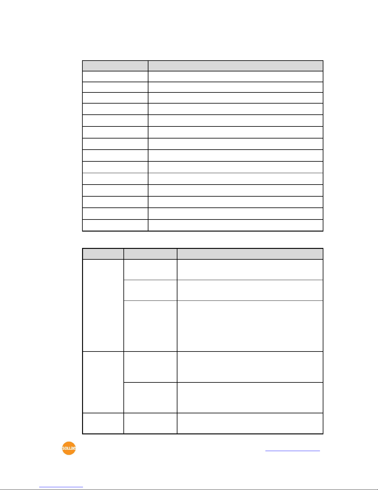
5.2.4 Comparison of Operation Modes
The following table is the comparison of the above described operation modes.
Mode
How to Initiate
Description
Serial Port
Communication Speed
Normal
ISP- pin open
or Pull-up
Normal data
communication mode
T2S, ATC, COD, U2S
User setting
Serial
Configuration
ISP- pin to Low
for 20ms ~
1000ms
Configuring the
environmental variables
through the serial
115200bps,N,8,1
Using the COM1 port

CSE-M32 User Manual Ver. 3.2
Sollae Systems Co., Ltd. - 9 - https://www.ezTCP.com
port.(COM1)
ISP
ISP- pin pull-
down
Download firmware
through the Ethernet
port
All security functions
are disabled
115200bps,N,8,1
Using the COM1 port
5.3 Normal Communication Mode
Normal communication mode is suitable for the purpose of using CSE-M32.
Normal communication mode can be classified into four modes – T2S, ATC, COD, and
U2S – each of which is described in the following table.
Communi-
cation
Mode
Protocol
Connection
Need for User
Equipment
Software
Modification
Configuration of
Environmental
Variables through
Serial Port
Topology
T2S
TCP
Passive
Connection
Not needed
Impossible
1:1
ATC
TCP
Active
/Passive
Connection
Needed
Possible
1:1
COD
TCP
Active
Connection
Not needed
Impossible
1:1
U2S
UDP
No
Connection
Not needed
Impossible
N:M
TCP protocol requires connection process. The connection is always established as 1:1
connection. At this time, the host waiting for connection (passive connection) is called a
server and the one attempting to connect (active connection) is called a client.
On the other hand, UDP communicates by block unit without connection process. As
UDP does not require connection, numbers of hosts can communicate at the same time.
5.4 Serial Configuration Mode
This mode is for configuration under condition which the network is unavailable. When
entering this mode, parameters of CSE-M32 can be set by its COM1 port. [Serial] tap on
the ezManager let users do this.
CSE-M32 User Manual Ver. 3.2
Sollae Systems Co., Ltd. - 10 - https://www.ezTCP.com
5.5 ISP Mode
5.5.1 Upgrading Firmware
In ISP mode, you can download a firmware (CSE-M32 operation software) provided by
our company. There is another thing in this mode. If you forget your password set before,
you can reset it by entering this mode. In ISP mode, all the security options including
ezTCP firewall are removal.
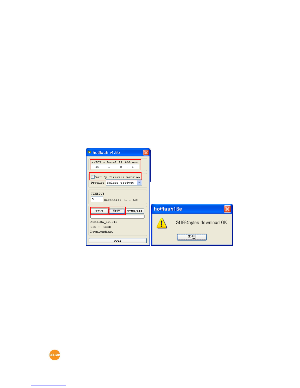
The following is the firmware downloading procedure.
⚫ Supply power with ISP- pin low, then CSE-M32 operates in the ISP mode.
⚫ Run hotflash that is supplied by us and input IP address of CSE-M32 and select the
firmware with the [FILE] menu. Then, send it with [SEND] button. (Uncheck the
[Verify firmware version] option.)
⚫ When the downloading is completed, set the ISP- pin to High and reset it in order
to enter normal mode again.
Firmware download can be implemented with ezManager whose version is
3.0A or subsequent version.
CSE-M32 User Manual Ver. 3.2
Sollae Systems Co., Ltd. - 11 - https://www.ezTCP.com
6 Normal Communication Mode
6.1 T2S – TCP Server
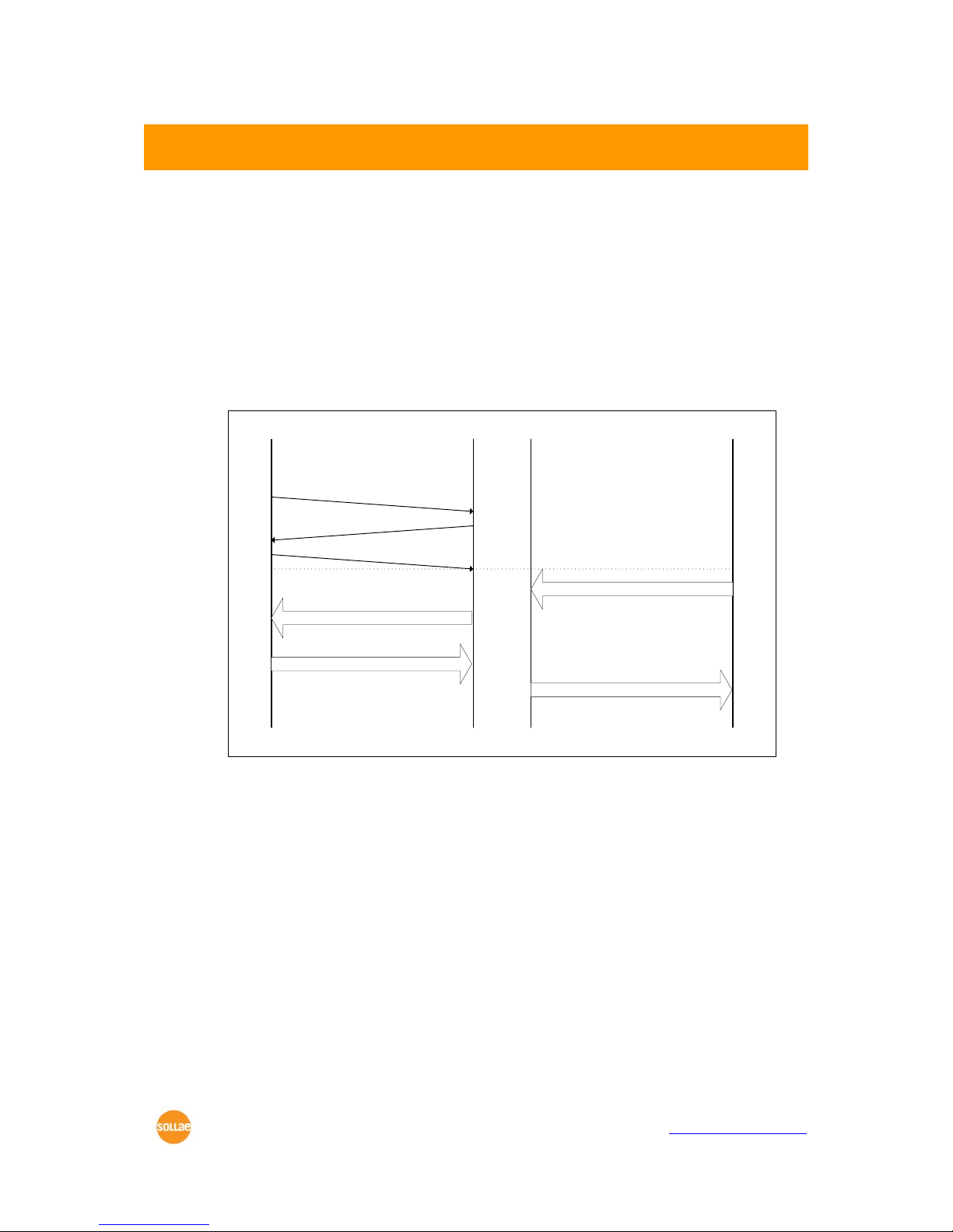
In T2S mode, the CSE-M32 functions as a server.
When a host connects to predefined local port, the CSE-M32 accepts a TCP
connection. When the ezTCP accepts TCP connection, then the TCP connection is
established. After connection is established, TCP/IP processing is performed on the data
coming to the serial port, which is then transmitted to the remote host. And the TCP/IP
data coming from the remote host is TCP/IP-processed and transmitted to the serial port to
establish data communication.
Remote Host Serial DeviceezTCP
Listen on
local port
Request TCP connection
Accept TCP connection
ack
DATA “ABC”
DATA “ABC” (TCP/IP)
DATA “DEF” (TCP/IP)
DATA “DEF”
connected
<T2S Mode>
6.1.1 TCP Connection
If a host connects to the pre-defined [Local Port] of CSE-M32, the host can communicate
bi-directionally.
6.1.2 Serial Data before the TCP Connection
The received serial data before the TCP connection is established will be handled based
on the [Event Byte] settings. If the [Event Byte] is 0, the data that comes to serial port of
CSE-M32 will not be recognized. If it is not 0, the serial data before TCP connection will be
temporarily saved to be sent to the host after the connection.
6.1.3 Data Transmission
When the TCP connection is established, the data communication in between the host
and the serial device will be established. Then, CSE-M32 will send data according to the
[Data Frame]. In other words, when the data comes through CSE-M32’s serial port, it will be

CSE-M32 User Manual Ver. 3.2
Sollae Systems Co., Ltd. - 12 - https://www.ezTCP.com
temporarily saved in the buffer. Then, when there is no incoming data during the
designated [Data Frame], CSE-M32 will send the saved data. If the [Data Frame] is 0, CSEM32 will send serial port’s data immediately. The unit used for the [Data Frame] is 10m
seconds, so CSE-M32 rounds down rest of the values.
6.1.4 Disconnection
When the connected host terminates the connection, or there is no data communication
during the designated [Timeout], the TCP connection will be automatically terminated. The
unit used for [Timeout] is 1 second.
6.2 COD – TCP Client
In COD mode, the ezTCP functions as a client.
When data of the pre-specified size [Event Byte] comes to the serial port, the ezTCP
attempts a TCP connection to the TCP port [Peer Port] of the preset host IP [Peer IP
Address]. If the remote host accepts the TCP connection, TCP connection will be
established. Data coming to the serial port after connection establishment is TCP/IPprocessed and transmitted to the remote host. And, data coming from the remote host is
TCP/IP-processed and transmitted to the serial port for data communication.
6.2.1 Serial Data before the TCP Connection
Data before TCP connection will be handled based on the [Event Byte] settings. If the
[Event Byte] is 0, the data that comes to CSE-M32’s serial port will not be recognized. If it is
not 0, the serial data before TCP connection will be temporarily saved to be sent to the
host after the connection.

CSE-M32 User Manual Ver. 3.2
Sollae Systems Co., Ltd. - 13 - https://www.ezTCP.com
6.2.2 Data Transmission
When the TCP connection is established, the data communication in between the host
and the serial device will be established. Then, CSE-M32 will send data according to the
[Data Frame]. In other words, when the data comes through CSE-M32’s serial port, it will be
temporarily saved in the buffer. Then, when there is no incoming data during the
designated [Data Frame], CSE-M32 will send the saved data. If the [Data Frame] is 0, CSEM32 will send serial port’s data immediately. The unit used for the [Data Frame] is 10
milliseconds, so CSE-M32 rounds down rest of the values.
6.2.3 Disconnection
When the connected host terminates the connection, or there is no data communication
during the designated [Timeout], the TCP connection will be automatically terminated. The
unit used for [Timeout] is 1 second.
6.2.4 DNS
If users set the host name instead of the IP address on the [Peer Address] box, CSE-M32
query the IP address of the host to its Domain Name Server (DNS). The IP address of DNS
can be configured on ezManager. If you set incorrect address on that box, the connection
won’t be established.

CSE-M32 User Manual Ver. 3.2
Sollae Systems Co., Ltd. - 14 - https://www.ezTCP.com
6.3 ATC
AT command is a mode which users control CSE-M32 with AT command like controlling
modem. In this mode, active and passive TCP connections are available. And users are
allowed to configure some environmental parameters with extended commands.
6.3.1 Key parameters
The configuration should be implemented via the serial port of CSE-M32.
Table 6-1 some of extended commands for configuration
Commands
Description
Examples
+PLIP
Local IP Address
at+plip=10.1.0.1<CR>
+PLP
Local Port
at+plp=1470<CR>
+PRIP
Peer IP Address
at+prip=10.1.0.2<CR>
+PRP
Peer Port
at+prp=1470<CR>
+PDC
DHCP
at+pdc=1 (ON)<CR>
+PPE
PPPoE
at+ppe=1 (ON)<CR>
+PTO
Timeout
at+pto=10<CR>
+PWP
Store setting
at+pwp<CR>
⚫ Related items with IP Address and Local Port
Local port can be set as well as IP address related parameters like IP Address, Subnet
Mask and Gateway IP Address.
⚫ Peer Address / Peer Port
IP address and local port of a remote host are can be set.
⚫ Type of assigning IP address: Manual, DHCP, PPPoE
Not only manual setting, also automatic assigning protocol (DHCP, PPPoE) are
available.
⚫ Others
Some of options including [Timeout] can be configured in this mode.

CSE-M32 User Manual Ver. 3.2
Sollae Systems Co., Ltd. - 15 - https://www.ezTCP.com
6.3.2 Examples
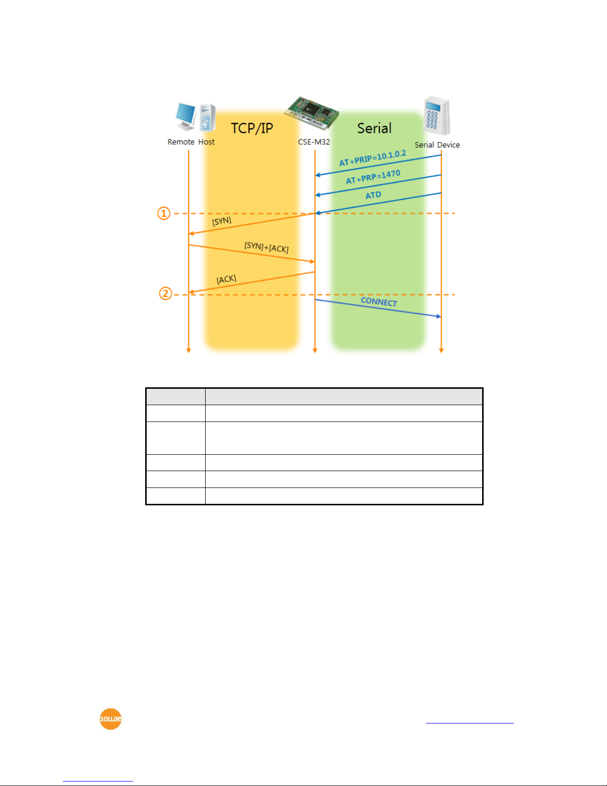
⚫ TCP Server – setting parameters and passive connection
Figure 6-1 TCP passive connection
Table 6-2 states of each point
Points
States
~
Set parameters in the AT command mode
①
CSE-M32 listens TCP connection requests with the ATA
command
~
CSE-M32 is listening TCP connection requests
②
A remote host has sent SYN segment to CSE-M32
~
Processes of TCP connection
③
TCP connection has been established
~
CSE-M32 sends “CONNECT” message to the serial port
Most of the response messages from the serial port of CSE-M32 are omitted
on above figure.
CSE-M32 User Manual Ver. 3.2
Sollae Systems Co., Ltd. - 16 - https://www.ezTCP.com
⚫ TCP Client – setting parameters and active connection
Figure 6-2 TCP Active connection
Table 6-3 states of each point
Points
States
~
Set parameters in the AT command mode
①
CSE-M32 sends a TCP connection request with the ATD
command
~
Processes of TCP connection
②
TCP connection has been established
~
CSE-M32 sends “CONNECT” message to the serial port

CSE-M32 User Manual Ver. 3.2
Sollae Systems Co., Ltd. - 17 - https://www.ezTCP.com
⚫ Termination of online status – entering the AT command mode
Figure 6-3 Termination of online status
Table 6-4 states of each point
Points
States
~
Keeps TCP connection
①
CSE-M32 enters the AT command mode with receiving “+++”
~
Keeps AC command mode
②
CSE-M32 terminates TCP connection with ATH command
~
Processes of TCP disconnection
③
TCP connection has been terminated
~
CSE-M32 sends “NO CARRIER” with disconnection
CSE-M32 changes the mode to AT command, when receiving “+++” and sending “OK”
message. In this state, the communication with remote host is not possible because CSEM32 processes only AT command. Whenever you want to go back to online state (TCP
connection), use “ATO” command.
For more information about this, please refer to the “ATC mode” on the
[Download] >> [Technical Document] menu of our web site.

CSE-M32 User Manual Ver. 3.2
Sollae Systems Co., Ltd. - 18 - https://www.ezTCP.com
6.4 UDP
UDP has no processes of connection. In this mode, data is sent in block units. Therefore,
data that comes through CSE-M32’s serial port must be classified in block units to send it
elsewhere.
6.4.1 Key parameters
⚫ Block Size(Byte)
[Block Size(Byte)] means the size of a block in UDP mode. Its unit is byte. The size of
bytes are come into the serial port, CSE-M32 sends them as one block to the
network. The maximum value could be 1460 bytes.
⚫ Data Frame
[Data Frame] means the time for gathering data to make one block. Its unit is 10ms.
If there are no transmission during the time which is set to this value, CSE-M32 sends
gathered data in the buffer as one block to the network.
Please set this value to 11 or higher values for correct operation.
Once one of the parameters is sufficient, the block size is decided as the
condition.
⚫ Dynamic update of Peer host
If users set the value of [Peer Address] and [Peer Port] to 0, [dynamic update of peer
host] function is activated. By using this function, CSE-M32 can communicate to
multiple hosts without additional setting.
This function is available on 1.2H or subsequently released firmware version.
CSE-M32 User Manual Ver. 3.2
Sollae Systems Co., Ltd. - 19 - https://www.ezTCP.com
6.4.2 Examples
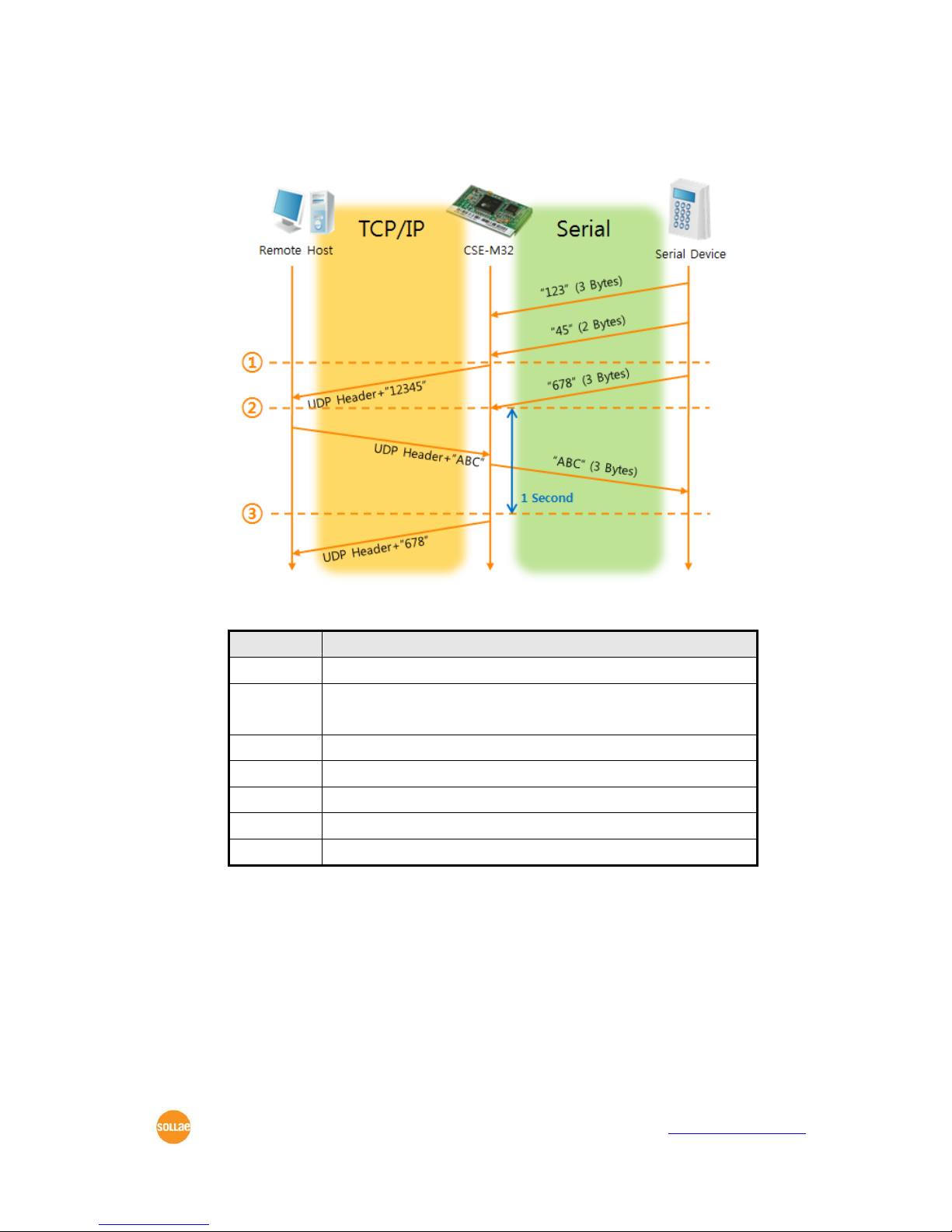
⚫ Block Size: 5 bytes / Data Frame: 1s (100 by 10ms)
Figure 6-4 time chart for Block Size is 5 bytes and data frame is 1s
Table 6-5 states of each point
Points
States
~
CSE-M32 is receiving data from the serial port
①
CSE-M32 Sends 5 bytes as one block based on the [Block
Size]
~
Serial device sends data “678” to the CSE-M32
②
Data “678” has arrived
~
CSE-M32 sends data from the remote host to the serial device
③
1 second has passed
~
CSE-M32 sends data “678” based on the [Data frame]

CSE-M32 User Manual Ver. 3.2
Sollae Systems Co., Ltd. - 20 - https://www.ezTCP.com
⚫ Dynamic Update of Peer host
This is a function that CSE-M32 automatically sets its peer host with information of
the last packet which is received from network. In the packet, the source address and
port number is used.
Table 6-6 setting for [dynamic update of peer host] function
Parameters
Values
Peer Address
0 (None)
Peer Port
0
Figure 6-5 time chart for [dynamic update of peer host]
Table 6-7 states of each point
Points
States
~
Remote host 2 sends data to CSE-M32
①
CSE-M32 sets host 2 to peer host
~
Remote host 1 sends data to CSE-M32
②
CSE-M32 updates host 1 to peer host
~
Remote host 2 sends data again to CSE-M32
③
CSE-M32 updates host 2 to peer host
~
CSE-M32 can communicate with remote host 2
The data “ABC”, “DE”, “FGH” are from the serial port of CSE-M32 in the Fig 6-
5.

CSE-M32 User Manual Ver. 3.2
Sollae Systems Co., Ltd. - 21 - https://www.ezTCP.com
7 Security Protocols & Option
7.1 SSL
7.1.1 SSL (Secure Socket Layer)
SSL is cryptographic protocol that provides secure communication on the Internet. The
SSL works over TCP.
7.1.2 How to set the SSL on CSE-M32
To works for SSL, you have to set the SSL-related parameters as the following steps.
⚫ Set the [SSL] check box in the ezManager.
⚫ Log in the CSE-M32 with telnet client.
For telnet login, please refer to the section 8.1.1
⚫ Generate an RSA key with a command. CSE-M32 supports 512, 768, and 1024
length keys.
Command Format: rsa keygen [key length]
⚫ Make a certificate with a ‘cert new’ command. The certificate is a self signed.

CSE-M32 User Manual Ver. 3.2
Sollae Systems Co., Ltd. - 22 - https://www.ezTCP.com
⚫ Save the parameters for SSL with a ‘ssl save aa55cc33’ command.
7.1.3 Restriction
To use the SSL with CSE-M32, there is a restriction. You can use only one serial port
(COM1) if you set the SSL function.
7.2 SSH
7.2.1 SSH (Secure Shell)
SSH is a network protocol that allows secure communications between two devices. You
can use this function if your device is a serial port for console and you need secure
communication.
7.2.2 How to set the SSH on CSE-M32
To works for SSL, you have to set the SSH-related parameters as the following steps.
⚫ Set the [SSH] check box in the ezManager.
⚫ Log in the CSE-M32 with telnet client.
For telnet login, please refer to the section 8.1.1
⚫ Generate an RSA key with a command. CSE-M32 supports 512, 768, and 1024
length keys.
Command Format: rsa keygen [key length]
CSE-M32 User Manual Ver. 3.2
Sollae Systems Co., Ltd. - 23 - https://www.ezTCP.com
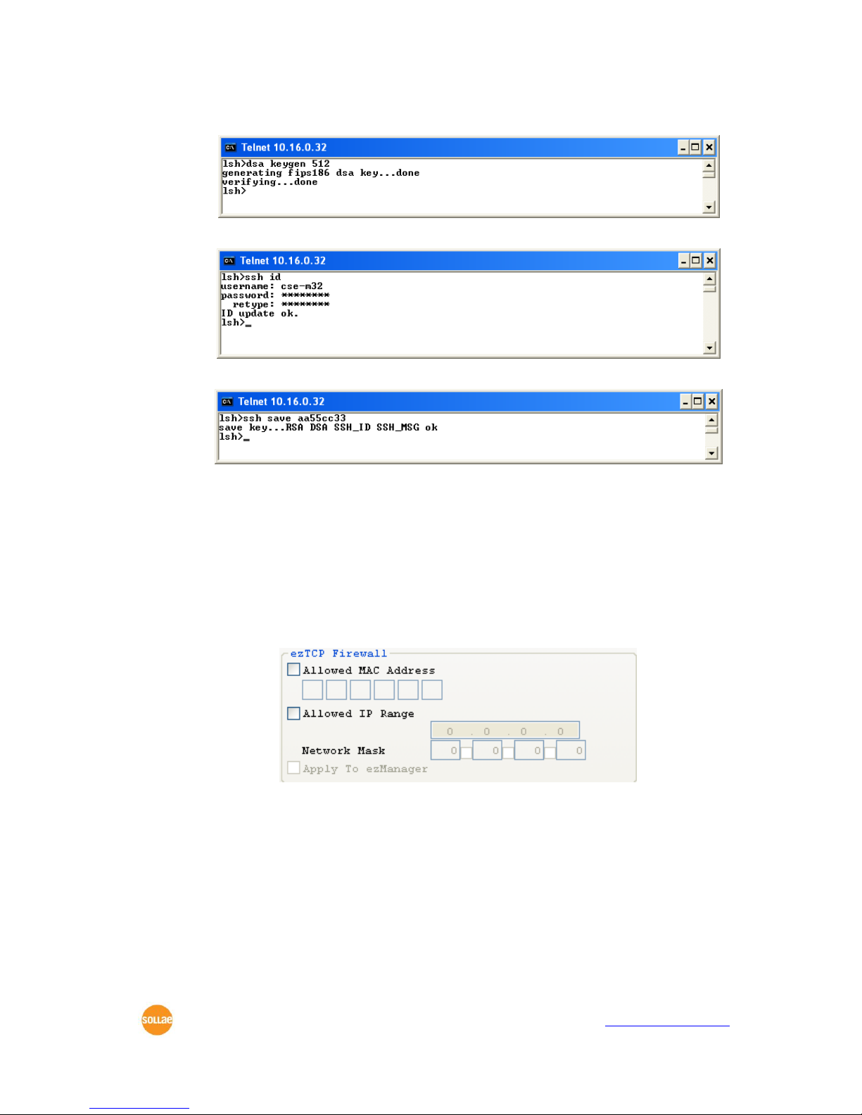
⚫ Generate a DSA key with a ‘dsa keygen’.
⚫ Set a username and a password to log in with a ‘ssh id’ command for the SSH.
⚫ Save the parameters for SSH with a ‘ssh save aa55cc33’ command.
7.2.3 Restriction
To use the SSH function with CSE-M32, there is a restriction. You can use only T2S
mode (TCP Server mode) if you set the SSH function
7.3 ezTCP Firewall
CSE-M32 has two connection limitation functions. Those can be set by the [Option] tab
of the ezManager.
⚫ Allowed MAC Address
If user sets the [Allowed MAC Address], the only specified host can be connected with
the CSE-M32.
⚫ Allowed IP Range
When the [Allowed IP] is set, the only hosts that are specified by [Allowed IP] and
[Network Mask] can connect to the CSE-M32.

CSE-M32 User Manual Ver. 3.2
Sollae Systems Co., Ltd. - 24 - https://www.ezTCP.com
⚫ examples
Allowed IP
Net Mask
Hosts who can connect to the CSE-M32
10.1.0.1
255.0.0.0
10.1.0.1 ∼ 10.255.255.254
10.1.0.1
255.255.255.0
10.1.0.1 ∼ 10.1.0.254
192.168.1.4
255.255.255.255
192.168.1.4
⚫ Apply to ezManager
If this option is checked, hosts who are not specified above two restrictions can’t
search and configure CSE-M32 with ezManager. This is enabled when one of
restrictions is set at least.
All security functions are disabled in the ISP mode. So user can access the
CSE-M32 in the ISP mode even though user can’t access the CSE-M32 in the
normal mode because of the [ezTCP Firewall] function.

CSE-M32 User Manual Ver. 3.2
Sollae Systems Co., Ltd. - 25 - https://www.ezTCP.com
8 Checking & Debugging
If user logs in the CSE-M32, user can monitor CSE-M32 status. And if user sets the
debugging option, user can get debugging data with ezManager.
8.1 Telnet
8.1.1 Telnet Login
Once the [TELNET] option is activated, users can remotely log in to CSE-M32. If a
password is set, users should input the password.
Starting with firmware version 2.0A, you can login by entering "sollae"
without setting a password.
After then, messages from CSE-M32 appear like the below figure.
8.1.2 Commands
⚫ Network Status
User can monitor network status of CSE-M32 with the “st net” command.
⚫ Serial Ports’ Status
User can monitor the statuses of two serial ports with the “st sio” command. The tx_count
and the rx_count are the total data sizes to/from the serial ports.

CSE-M32 User Manual Ver. 3.2
Sollae Systems Co., Ltd. - 26 - https://www.ezTCP.com
⚫ Checking Uptime
With “st uptime” command, you can check the time of your device boots up.
⚫ Serial Ports I/O data capture
This command is available on 1.2H or subsequently released firmware version. User can
monitor the input / output data of CSE-M32’s serial ports with the “sd” command. The way
of using this command is like below.
“sd [SPACE] [# of Serial Port] [SPACE] [Interval]”
The value of [# of Serial Port] is that COM1 is “1” and COM2 is “2”. [Interval] means
duration of capturing and printing data on your screen and its unit is mille second (ms).
For example, if you want to capture the data in every second, the value of [Interval]
should be 100.
⚫ Termination of TCP connection
Using “sc” command, users can terminate established TCP connection. The way of using
this command is like below.
“sc [SPACE] [Name of Serial Port] [SPACE] close”
CSE-M32 User Manual Ver. 3.2
Sollae Systems Co., Ltd. - 27 - https://www.ezTCP.com
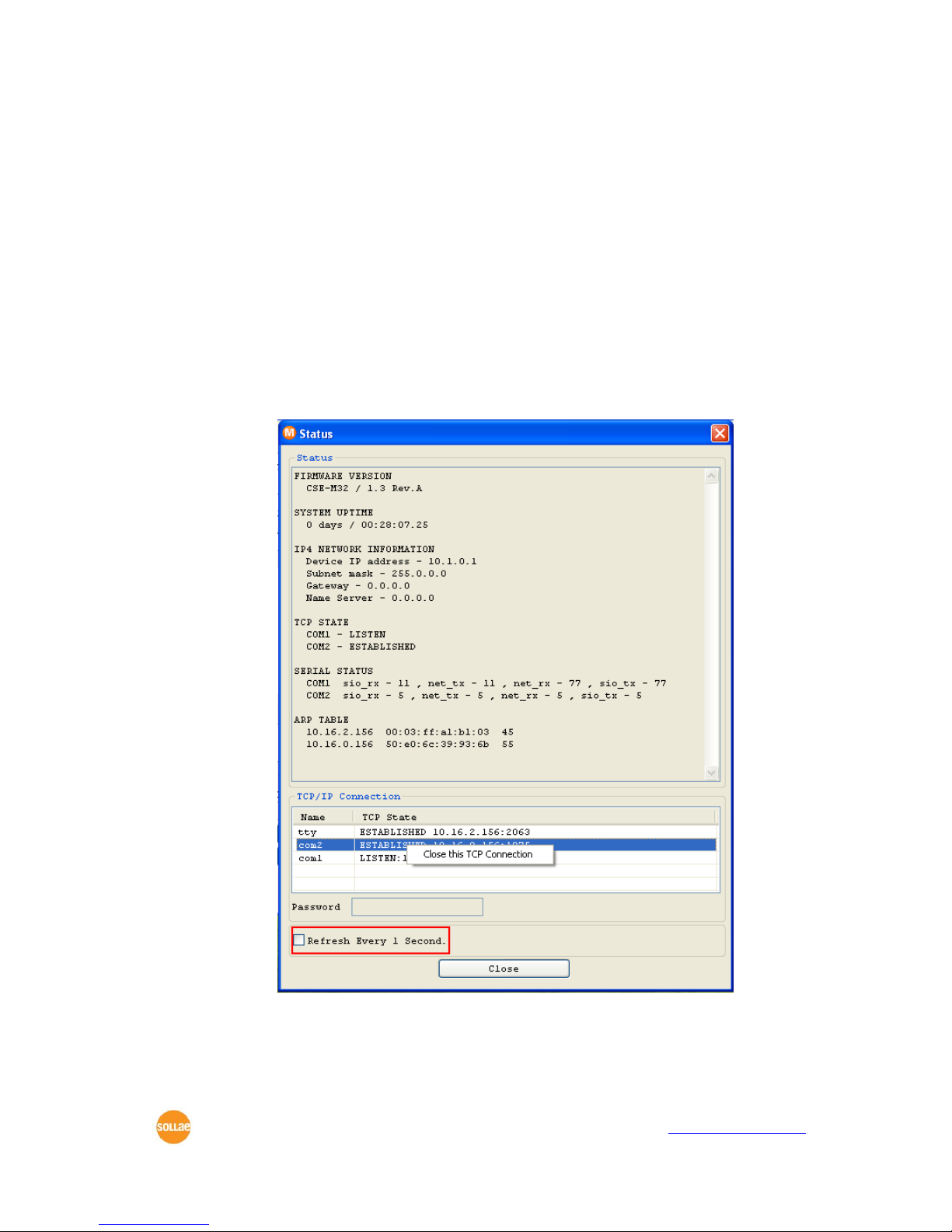
8.2 Status on ezManager
8.2.1 Status of the CSE-M32
If the [Status] button is pressed on ezManager, user can monitor the current status of the
CSE-M32 with ezManager. If user sets [Refresh Every 1 second] option, the status data will
be updated in every second.
8.2.2 Closing TCP connection by the ezManager
User can terminate a TCP connection with the status window of the ezManager. If use r
clicks the right button of each TCP connection message of the TCP/IP Connection, user can
terminate the TCP connection.

CSE-M32 User Manual Ver. 3.2
Sollae Systems Co., Ltd. - 28 - https://www.ezTCP.com
8.3 Remote Debugging
If the [Debugging Message] field in the [OPTION] tab of the ezManager, CSE-M32
transmits debugging messages with UDP port 50006. Then user can get the messages with
new window if user presses [Debugging Message] button as followed:
This function is very useful when there are any problems when users install the CSE-M32
in the user site.

CSE-M32 User Manual Ver. 3.2
Sollae Systems Co., Ltd. - 29 - https://www.ezTCP.com
9 The Evaluation Board
9.1 Introduction
This board is for testing the CSE-M32 with an Ethernet interface and 2 RS232 interfaces.
9.2 Connectors
Part
Name
Description
JP6
DC JACK
It supplies the power to the CSE-M32. The input voltage
should be 5V. The regulator in the evaluation board
regulate the 5V to 3.3V and supplies the 3.3V to the
CSE-M32.
CON1
RJ45
10M/100M Ethernet
P1
DB9M
RS232 interface for COM1 (UART0)
P2
DB9M
RS232 interface for COM2 (UART1)
JP3
Header
Alternate port of JP1 of CSE-M32
JP4
Header
Alternate port of JP2 of CSE-M32
JP7
Connector
The console port of CSE-M32. It is for factory but not for
customers.
JP8
Header
The SPI port. CSE-M32 doesn’t use this port.

CSE-M32 User Manual Ver. 3.2
Sollae Systems Co., Ltd. - 30 - https://www.ezTCP.com
9.3 Jumpers and Switches
9.3.1 JP5
It is for ISP of CSE-M32.
Connection
The input signal to the ISP
Description
1-2 short
High
Normal Mode
2-3 short
Low
ISP Mode
When CSE-M32 boots up, it operates as Normal mode when the ISP is high. It operates
as ISP mode when the ISP is low.
9.3.2 JP9, JP10
These pins control the outputs of the RS232 line drivers.
Connection
Input value of RS232 driver
Description
1-2 short
High
RS232 driver is active
2-3 short
Low
RS232 driver is inactive
(high impedance)
These jumpers are very useful to connect user serial port and CSE-M32 with 3.3V level
directly.
9.3.3 Reset Switch (S1)
It resets CSE-M32 by putting low signal to the RESET pin of CSE-M32.
CSE-M32 User Manual Ver. 3.2
Sollae Systems Co., Ltd. - 31 - https://www.ezTCP.com
9.4 System LEDs classified each mode
Mode
Name
Color
Status
Description
Common
PWR
Red
On
Supplying the power
Normal
LAN
STS
Yellow
Blinks in
every
second
Being assigned IP address
Blinks 4
times in a
second
Being not assigned IP address via
DHCP or PPPoE
LAN
LINK
Green
On
Connecting with Ethernet
LAN_RX
Yellow
Blinks
Receiving data from Ethernet
LAN_TX
Green
Blinks
Sending data to Ethernet
SIO1
/SIO2
RXD0/1
Yellow
Blinks
Receiving data from Serial ports
TXD0/1
Green
Blinks
Sending data from Serial ports
RTS0/1
Green
On
Available to Receiving data
(Using RTS/CTS Flow Control)
CTS0/1
Yellow
On
Available to Sending data
(Using RTS/CTS Flow Control)
-
CN0/1
Yellow
On
Establishing TCP connection
ISP
-
All
(except
PWR)
-
Off
Entering ISP mode
Serial
Configur-
ation
LAN
LINK/
LAN_RX
/
LAN_TX/
STS
-
Blinks
simultaneo
usly
Entering Serial Configuration
mode
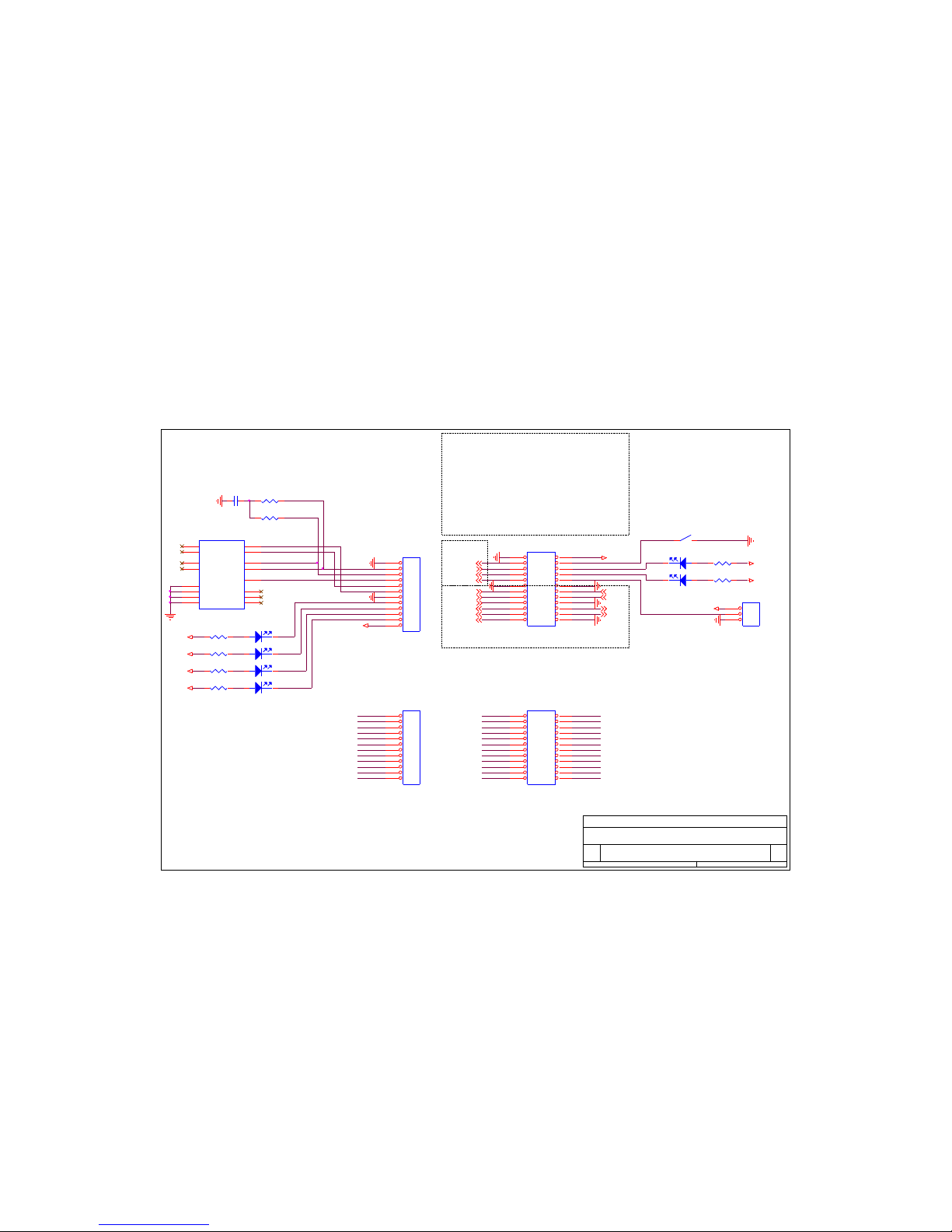
9.5 Schematic of the evaluation board
JP4
HEADER 12X2
1 2
3 4
5 6
7 8
9 10
11 12
13 14
15 16
17 18
19 20
21 22
23 24
JP2_18
TP_OUT-
VCC_33
JP2_17
JP1_7
MISO2
JP2_20
CN0
DRXD, DTXD: FOR FACTORY USE
JP1_11
D3
LED
1 2
RXD12
JP2_23
C1
100nF
JP1_1
JP2_11
JP2_24
JP1_8
JP5
HEADER 3
1
2
3
JP1_4
JP2_14
D1
LED
12
R7
330
JP1_9
JP2
HEADER 12X2
1 2
3 4
5 6
7 8
9 10
11 12
13 14
15 16
17 18
19 20
21 22
23 24
JP3
HEADER 12
1
2
3
4
5
6
7
8
9
10
11
12
ISP-
VCC_33
JP2_6
JP2_4
D6
LED
1 2
R4
330
SYS_RST-
TP_IN-
LAN_TX_LED-
JP2_13JP1_6
JP2_19
PWFBOUT
D2
LED
12
JP1_3
JP2_6
JP2_10
JP1_2
JP2_24
JP2_17
JP2_8
JP1_12
JP1_2
VCC_33
JP2_13
JP2_3
JP2_15
JP2_14
JP2_16
TXD0 2
JP2_7
JP1_5
DTXD2
JP1_1
JP2_1
R8
330
JP1
HEADER 12
1
2
3
4
5
6
7
8
9
10
11
12
JP2_19
VCC_33
JP1_8
JP2_21
JP2_12
CTS12
JP1_7
JP2_20
UART
SYS_RST-: INPUT
HIGH - NORMAL,
LOW - RESET
CON1
RD1-126BAG1A
1
2
3
7
8
4
5
6
13
14
15
16
12
11
10
9
TD+
TD-
CT
RD+
RD-
NC
NC
NC
CH_GND 1
CH_GND 2
HOLE1
HOLE2
LED_A+
LED_A-
LED_B+
LED_B-
JP1_10
SCK2
JP1_11
JP1_6
R5
330
CN0, CN1: OUTPUT
HIGH - WHEN TCP DISCONNECTED
LOW - WHEN TCP CONNECTED
LINK_LED-
JP2_10
JP1_10
LAN_RX_LED-
JP1_4
D4
LED
1 2
TXD12
JP1_5
JP2_18
STS_LED-
CN1
VCC_33
RTS12
JP2_16
JP2_12
JP1_3
VCC_33
JP1_12
R3
330
JP2_22
JP2_7
JP2_2
JP2_22
MAIN V1.1
CSE-M30 EVALUATION B/D
A4
1 2화요일, 1월 16, 2007
Title
Size Document Number Rev
Date: Sheet of
CTS0 2
JP2_5
R6
330
VCC_33
JP2_21
TP_IN-
JP1_9
SPI
RTS0 2
NSS2
JP2_9
JP2_3
JP2_2
TP_IN+
TP_IN+
D5
LED
1 2
ISP-: INPUT
HIGH - NORMAL, LOW - F/W UPGRADE
TP_OUT+
JP2_5
JP2_8
DRXD2
JP2_15
MOSI2
RXD0 2
R1 49.9 (1%)
JP2_1
R2 49.9(1%)
JP2_11
VCC_33
JP2_4
S1
SWITCH
JP2_23
VCC_33
JP2_9

CSE-M32 User Manual Ver. 3.2
Sollae Systems Co., Ltd. - 1 - https://www.ezTCP.com
VCC_33
H2
HOLE-2
1
1
VCC_33
VCC_33
U2 AMS1117-3.3
23
1
4
VOUTVIN
G
TAB
+
C6 100nF
12
H1
HOLE-2
1
1
SPI
VCC_33
VCC_33
RXD0
D7
1N4001
12
CTS01
RXD1
R12
330
TXD01
CTS1
EN_COM1
+
C9
10uF
R17
330
CTS11
VCC_33
U1
SP3243
4
5
6
7
8
19
18
20
17
16
15
14
13
12
9
10
11
26
25
28
24
1
2
27
3
23
22
21
R1IN
R2IN
R3IN
R4IN
R5IN
R1OUT
R2OUT
R2OUT
R3OUT
R4OUT
R5OUT
T1IN
T2IN
T3IN
T1OUT
T2OUT
T3OUT
VCC
GND
C1+
C1-
C2+
C2-
V+
V-
ONLINE
SHUTDOWN
STATUS
R14
330
RXD1
VCC_33
CTS0
+
C5 100nF
1 2
SCK1
D10
LED
1 2
D9
LED
1 2
H3
HOLE-2
1
1
NSS1
BP2
100nF
1
2
B1
ACH3218-152
1
2
3
IN
GND
OUT
VCC_33
+
C2 100nF
12
VCC_33
RTS1
TXD11
D11
LED
1 2
P1
CONNEC TOR DB9
5
9
4
8
3
7
2
6
1
10
11
+
C8
10uF
RXD01
JP7
HEADER 6
1
2
3
4
5
6
D12
LED
1 2
CONSOLE
+
C10 100nF
1 2
VCC_33
DRXD1
VCC_EXT
EN_COM2
TXD0
D16
LED
1 2
EN_COM1
VCC_5
VCC_33
CTS0
R10
330
HIGH: ENABLE RS232 DRIVER
LOW: DISABLE RS232 DRIVER
VCC_33
TXD0
H4
HOLE-2
1
1
D13
LED
1 2
POWER V1.1
CSE-M30 EVALUATION B/D
A4
2 2화요일, 1월 16, 2007
Title
Size Document Number Rev
Date: Sheet of
+
C3
100nF
1 2
R11
330
VCC_5
VCC_33
RXD11
DTXD1MISO1
RTS1
R9
330
VCC_33
+
C4 100nF
1 2
CTS1
RTS11
JP10
HEADER 3
1
2
3
D15
LED
1 2
VCC_33
JP6
POWER J ACK
1
2
3
5V
GND
GND
VCC_33
D14
LED
1 2
+
C11 100nF
1 2
EN_COM2
JP9
HEADER 3
1
2
3
R13
330
VCC_33
RXD0
D8
LED
1 2
R15
330
VCC_33
BP1
100nF
1
2
U3
SP3243
4
5
6
7
8
19
18
20
17
16
15
14
13
12
9
10
11
26
25
28
24
1
2
27
3
23
22
21
R1IN
R2IN
R3IN
R4IN
R5IN
R1OUT
R2OUT
R2OUT
R3OUT
R4OUT
R5OUT
T1IN
T2IN
T3IN
T1OUT
T2OUT
T3OUT
VCC
GND
C1+
C1-
C2+
C2-
V+
V-
ONLINE
SHUTDOWN
STATUS
JP8
HEADER 4
1
2
3
4
RTS0
MOSI1
RTS01
TXD1
TXD1
VCC_33
R16
330
RTS0
+
C7
100nF
1 2
P2
CONNEC TOR DB9
5
9
4
8
3
7
2
6
1
10
11

10 Related material
10.1 Technical Documents
You can find the technical documents at our website.
⚫ DataSheet
⚫ IP Change Notification (DDNS)
⚫ How to use SSL
⚫ How to use SSH
⚫ Sending MAC Address function
⚫ Telnet COM Port Control Option
⚫ etc
10.2 Smart phone application
⚫ ezManager (iOS)
⚫ ezManager (Android)
⚫ TCP/IP Client (Android)

CSE-M32 User Manual Ver. 3.2
Sollae Systems Co., Ltd. - 1 - https://www.ezTCP.com
11 Technical Support and Warranty
11.1 Technical Support
If you have any question regarding operation of the product, visit Customer Support FAQ
corner and the message board on Sollae Systems’ web site or send us an email at the
following address:
⚫ E-mail: support@eztcp.com
⚫ Website Address for Customer Support: https://www.eztcp.com/en/support/
11.2 Warranty
11.2.1 Refund
Upon the customer’s request to refund the product within two weeks after purchase,
Sollae Systems will refund the product.
11.2.2 Free Repair Services
For product failures occurring within two years after purchase, Sollae Systems provides
free repair services or exchange the product. However, if the product failure is due to
user’s fault, repair service fees will be charged or the product will be replaced at user’s
expense.
11.2.3 Charged Repair Services
For product failures occurring after the warranty period (two years) or resulting from
user’s fault, repair service fees will be charged and the product will be replaced at user ’s
expense.

CSE-M32 User Manual Ver. 3.2
Sollae Systems Co., Ltd. - 2 - https://www.ezTCP.com
12 Precaution and Exemption from Liability
12.1 Precaution
⚫ Sollae Systems is not responsible for product failures occurring due to user’s
alternation of the product.
⚫ Specifications of the product are subject to change without prior notice for
performance improvement.
⚫ Sollae Systems does not guarantee successful operation of the product if the
product was used under conditions deviating from the product specifications.
⚫ Reverse engineering of firmware and applications provided by Sollae Systems is
prohibited.
⚫ Use of firmware and applications provided by Sollae Systems for purposes other
than those for which they were designed is prohibited.
⚫ Do not use the product in an extremely cold or hot place or in a place where
vibration is severe.
⚫ Do not use the product in an environment in which humidity is high or a lot of oil
exists.
⚫ Do not use the product where there is caustic or combustible gas.
⚫ Sollae Systems does not guarantee normal operation of the product under the
conditions a lot of noise exists.
⚫ Do not use the product for a purpose that requires exceptional quality and
reliability relating to user’s injuries or accidents – aerospace, aviation, health care,
nuclear power, transportation, and safety purposes.
⚫ Sollae Systems is not responsible for any accident or damage occurring while using
the product.

CSE-M32 User Manual Ver. 3.2
Sollae Systems Co., Ltd. - 3 - https://www.ezTCP.com
12.2 Exemption from Liability
12.2.1 English version
In no event shall Sollae Systems Co., Ltd. And its distributors be liable for any damages
whatsoever (including, without limitation, damages for loss of profit, operating cost for
commercial interruption, loss of information, or any other financial loss) from the use or
inability to use the CSE-M32 even if Sollae Systems Co., Ltd. Or its distributors have been
informed of such damages.
The CSE-M32 is not designed and not authorized for use in military applications, in
nuclear applications, in airport applications or for use in applications involving explosives,
or in medical applications, or for use in security alarm, or for use in a fire alarm, or in
applications involving elevators, or in embedded applications in vehicles such as but not
limited to cars, planes, trucks, boats, aircraft, helicopters, etc..
In the same way, the CSE-M32 is not designed, or intended, or authorized to test,
develop, or be built into applications where failure could create a dangerous situation that
may result in financial losses, damage to property, personal injury, or the death of people
or animals. If you use the CSE-M32 voluntarily or involuntarily for such unauthorized
applications, you agree to subtract Sollae Systems Co., Ltd. And its distributors from all
liability for any claim for compensation.
Sollae Systems Co., Ltd. And its distributors entire liability and your exclusive remedy
shall be Sollae Systems Co., Ltd. And its distributors option for the return of the price paid
for, or repair, or replacement of the CSE-M32.
Sollae Systems Co., Ltd. And its distributors disclaim all other warranties, either expressed
or implied, including, but not limited to, the implied warranties of merchantability and
fitness for a particular purpose, with respect to the CSE-M32 including accompanying
written material, hardware and firmware.
12.2.2 French version
⚫ Documentation
La documentation du boîtier CSE-M32 est conçue avec la plus grande attention. Tous les
efforts ont été mis en œuvre pour éviter les anomalies. Toutefois, nous ne pouvons garantir
que cette documentation soit à 100% exempt de toute erreur. Les informations présentes
dans cette documentation sont données à titre indicatif. Les caractéristiques techniques
peuvent changer à tout moment sans aucun préavis dans le but d'améliorer la qualité et les
possibilités des produits.

CSE-M32 User Manual Ver. 3.2
Sollae Systems Co., Ltd. - 4 - https://www.ezTCP.com
⚫ Copyright et appellations commerciales
Toutes les marques, les procédés, les références et les appellations commerciales des
produits cités dans la documentation appartiennent à leur propriétaire et Fabricant respectif.
⚫ Conditions d’utilisations et limite de responsabilité
En aucun cas Sollae Systems Co., Ltd. ou un de ses distributeurs ne pourra être tenu
responsable de dommages quels qu'ils soient (intégrant, mais sans limitation, les
dommages pour perte de bénéfice commercial, interruption d'exploitation commerciale,
perte d’informations et de données à caractère commercial ou de toute autre perte
financière) provenant de l'utilisation ou de l'incapacité à pouvoir utiliser le boîtier CSE-M32,
même si Sollae Systems Co., Ltd. ou un de ses distributeurs a été informé de la possibilité
de tels dommages.
Le boîtier CSE-M32 est exclusivement prévu pour un usage en intérieur, dans un
environnement sec, tempéré (+10 °C à +40°C) et non poussiéreux. Le boîtier CSE-M32 n’est
pas prévu, ni autorisé pour être utilisé en extérieur, ni de façon embarquée dans des engins
mobiles de quelque nature que ce soit (voiture, camion, train, avion, etc…), ni en milieu
explosif, ni dans des enceintes nucléaires, ni dans des ascenseurs, ni dans des aéroports, ni
dans des enceintes hospitaliers, ni pour des applications à caractère médical, ni dans des
dispositifs de détection et d’alerte anti-intrusion, ni dans des dispositifs de détection et
d’alerte anti-incendie, ni dans des dispositifs d’alarme GTC, ni pour des applications
militaires.
De même, le boîtier CSE-M32 n’est pas conçu, ni destiné, ni autorisé pour expérimenter,
développer ou être intégré au sein d’applications dans lesquelles une défaillance de celui-ci
pourrait créer une situation dangereuse pouvant entraîner des pertes financières, des
dégâts matériel, des blessures corporelles ou la mort de personnes ou d’animaux. Si vous
utilisez le boîtier CSE-M32 volontairement ou involontairement pour de telles applications
non autorisées, vous vous engagez à soustraire Sollae Systems Co., Ltd. et ses distributeurs
de toute responsabilité et de toute demande de dédommagement.
En cas de litige, l'entière responsabilité de Sollae Systems Co., Ltd. et de ses distributeurs
vis-à-vis de votre recours durant la période de garantie se limitera exclusivement selon le
choix de Sollae Systems Co., Ltd. et de ses distributeurs au remboursement de votre
produit ou de sa réparation ou de son échange. Sollae Systems Co., Ltd. et ses distributeurs
démentent toutes autres garanties, exprimées ou implicites.

CSE-M32 User Manual Ver. 3.2
Sollae Systems Co., Ltd. - 5 - https://www.ezTCP.com
Tous les boîtiers CSE-M32 sont testés avant expédition. Toute utilisation en dehors des
spécifications et limites indiquées dans cette documentation ainsi que les court-circuit, les
chocs, les utilisations non autorisées, pourront affecter la fiabilité, créer des
dysfonctionnements et/ou la destruction du boîtier CSE-M32 sans que la responsabilité de
Sollae Systems Co., Ltd. et de ses distributeurs ne puissent être mise en cause, ni que le
boîtier CSE-M32 puisse être échangé au titre de la garantie.
⚫ Rappel sur l’évacuation des équipements électroniques usagés
Le symbole de la poubelle barré présent sur le boîtier CSE-M32 indique que vous ne
pouvez pas vous débarrasser de ce dernier de la même façon que vos déchets courants.
Au contraire, vous êtes responsable de l’évacuation du boîtier CSE-M32 lorsqu’il arrive
en fin de vie (ou qu’il est hors d’usage) et à cet effet, vous êtes tenu de le remettre à un
point de collecte agréé pour le recyclage des équipements électriques et électroniques
usagés. Le tri, l’évacuation et le recyclage séparés de vos équipements usagés permettent
de préserver les ressources naturelles et de s’assurer que ces équipements sont recyclés
dans le respect de la santé humaine et de l’environnement. Pour plus d’informations sur les
lieux de collecte des équipements électroniques usagés, contacter votre mairie ou votre
service local de traitement des déchets.

CSE-M32 User Manual Ver. 3.2
Sollae Systems Co., Ltd. - 6 - https://www.ezTCP.com
13 Revision History
Date
Version
Comment
Author
Jan.15.2007
0.5
○ Initial touch
May.25.2007
1.0
○ Initial release
Aug.31.2007
1.1
○ Add Serial Interface
○ Add Ethernet Interface
○ Add Telnet COM Port Control Option
Sep.27.2007
1.2
○ Add DDNS(Dynamic DNS) Function
Dec.4.2008
1.3
○ Add SSL, SSH function
○ Modify ISP- pin function
○ Modify RTS/CTS Flow-control
○ Modify Test Method
○ Add AT+PNIP, AT+PRHN
○ Add Connect with a host name in ATC Mode
○ Add Close TCP function
Dec.11.2008
1.4
○ Add recommended RJ45 connectors
Jan.08.2009
1.5
○ Add Security Function in the ISP mode
Feb.26.2009
1.6
○ Add DC Electric Characteristics
Mar.04.2009
1.7
○ Add description of serial I/O data capture by using
telnet. (sd command)
○ Add description of U2S echo
○ Correct Some Expressions
Mar.31.2009
1.8
○ Add 10.4 System LEDs
○ Modify the table of 7.7.1
○ Modify 11.1 Technical Support
○ Correct Some Expressions
Apr.18.2009
1.9
○ Correct overlapped schematics
Jul.13.2009
2.0
○ Add description of Send MAC Address function
○ Add description of AT+PSE command
○ Add description of changing local port in ATC mode
○ Add description of Termination of TCP connection in
9.1.2
○ Add description of sc command in TELNET
○ Update most of pictures including ezManager and
Telnet
○ Modify the table of 10.4 System LEDs

CSE-M32 User Manual Ver. 3.2
Sollae Systems Co., Ltd. - 7 - https://www.ezTCP.com
○ Modify the 4.2 Configuration with ezManager
○ Modify the description about F/W upgrade
○ Modify the 4.6 Notify IP change
○ Change the form of document
○ Correct some expressions
Dec.02.2009
2.1
○ The table of “JP2” has been modified.
○ Form of Revision History has been modified.
○ Operating/Storage temperature has been added.
Roy LEE
Aug.03.2011
2.2
○ Add description of serial options. (FIFO, Data frame
interval… etc)
○ Update a screenshot of ezManager.
Amy KIM
Jan.11.2012
2.3
○ Caution about service using of DynDNS has been
added
○ Descriptions of FIFO function has been deleted.
Peter LEE
June.21.2012.
2.4
○ Extend the warranty period to two years
○ Remove description about PPPoE and DHCP
Peter LEE
Feb.14.2013
2.5
○ Add description of reset time
Peter LEE
May.14.2013
2.6
○ Add related material
○ Add exemption from liability
Peter LEE
Oct.28.2013
2.7
○ Modify current consumption
Peter LEE
Jan.02.2014
2.8
○ Correct some expressions
○ Modify the description about ATC mode
○ Modify the description about UDP
Peter LEE
Mar.22.2016
3.0
○ Add explanation for telnet login.
Peter LEE
Apr.25.2018
3.1
○ Change explanation for 3.3V TTL
Sara Lee
May.30.2018.
3.2
○ Update the application circuit
Roy LEE
 Loading...