

Solinst Levelogger Series, Rainlogger 3001, Leveloader Gold, Barologger 3001 Gold, Levelogger 3001 Gold User Manual
...
User Guide - Software Version 3.2.3
June 5, 2008
Levelogger Series
(Levelogger Gold, Barologger Gold, Levelogger Junior, and Rainlogger)

Levelogger User Guide - Table of Contents
1 Introduction to Solinst Levelogger Series and Software 4
1.1 Level 9
1.1.1 Pressure Calibration 9
1.2 Barologger 9
1.3 Temperature 10
1.4 Total Precipitation 10
1.5 Backwards Compatibility 10
2 System Requirements 11
3 Software Installation 11
3.1 Installing USB Drivers for Software V3.2.3 or Higher 12-15
- USB Installation for Windows 98 12
- USB Installation for Windows 2000 13
- USB Installation for Windows XP (Service Pack 2 or less) 14-15
4 Startup, Configuration and Settings 16
4.1 Communicating with a USB Port 16-17
4.2 Com Port Designation Setup 17
4.3 Data Directory 17
5 Levelogger Settings 18
5.1 Levelogger Information Settings 17-20
- Project ID 18
- Location, input specific site / location information 18
- Altitude 18
- Density Adjustment 19
- Sample Mode 19
- Memory Mode Selection 19
- Linear 19
- Event-based Sample Collection 19
- Schedule Sampling 19
5.2 Setting up Channel Information 20
- For Channel 1: ‘Level’... 21
- Identification 21
- Units 21
- Offset 21
- Range 21
- For Channel 2: ‘Temperature’... 21
5.3 Levelogger Status 22
5.4 Setting up the Levelogger Time 22
5.5 Program Levelogger Settings 22
5.6 Starting and Stopping the Levelogger 22-23
5.7 Saving and Retrieving Levelogger Settings Files 23
6 Rainlogger 24
6.1 Rainlogger Communication Interface 24
- Rainlogger Gauge Connector 24
6.2 Rainlogger Setup 25-26
7 Data Control Window (Downloading and Compensating Data) 27
7.1 Downloading Options 27-29
7.2 Graph Manipulation and Zoom Function 29-30
7.3 Data Compensation 31-32
- Barometric Compensation 32
- Manual Data Adjustment 32
- Density Adjustment 32
- Barometric Efficiency Adjustment 32

Levelogger User Guide - Table of Contents
8 Real Time View Window 33
9 File Export and Print Function 34
10 Installation and Maintenance of Levelogger
35-50
10.1 Installation 35
10.1.1 Free Suspended Installations 36-37
- Suspension Wire Installation 36
- Direct Read Cable Assembly Installation 37
10.1.2 Fixed Installation 37-45
- Open Channel Installations 37-39
- Installation at Weirs 40-41
- Installation in Flumes 41-42
- The California Pipe Method 42
- Orifice Discharge Monitoring 43
- Artesian Monitoring 43-44
- Vacuum/Vapor Monitoring 44-45
10.1.3 Barologger Installation 45
- Barometric Efficiency 45-46
10.1.4 Installation in Extreme Thermal and Marine
Environments 47-48
- Freezing or High Temperature Conditions 47
- Marine or Brackish Installations 48
10
.1.5 References 49
10.2 Levelogger Maintenance 50
11 Manual Barometric Compensation 51-54
12 Diagnostic Utility 54
12.1 Read Levelogger Information 54-55
12.2 Run Self-Test 55
12.3 Read Memory Dump 56
12.4 Create Report 57
13 Firmware Upload Utility 58
14 Trouble Shooting Guide 59-62
14.1 Problems During Installation of Levelogger Gold Software 59
14.2 Error During Software Uninstall Process 59
14.3 Problems During Installation of RS232 to USB Converter 59
14.4 Data Has Been Erased Accidentally 60
14.5 Error Messages During Use of Software 60-62
Appendix
i) 3001 Levelogger Gold Quick Start Guide
ii) 3001 Leveloader Gold User Guide
iii) 3001 Leveloader Gold Quick Start Guide

Levelogger User Guide - Software Version 3.2.3 or Higher
Page 4
1 Introduction to Solinst Levelogger Series and Software
Levelogger Gold Software Version 3.2.3 is intuitive and easy-to-use. It is
designed to support the Levelogger Gold Series of products.
Levelogger Gold
The Levelogger Gold is an absolute (non-vented) data logger, which measures
groundwater and surface water levels and temperature. Water levels are
displayed as temperature compensated pressure readings, and can be
barometrically compensated with the aid of a Barologger Gold.
- Solinst recommends customers use Version 3.2.3 Software using with
V2.000 firmware or higher
Levelogger Gold Technical Specifications
Level Sensor: Piezoresistive Silicon in 316L Stainless Steel
Accuracy (Typical): 0.05% FS
Stability of Readings: Superior, low noise, 6 times better than previously
Resolution: 0.002 to 0.0006% FS
Normalization: Automatic Temp Compensation
Temperature Sensor: Platinum Resistance Temperature Detector
Temp. Sensor Accuracy: ± 0.05°C
Temp. Sensor Resolution: 0.003°C
Temp. Comp. Range: -10 to +40°C
Response Time: < 1 minute
Battery Life: 10 Years - based on one reading/min
Clock Accuracy: ± 1 minute /year
Operating Temperature: -20°C to 80°C
Maximum # Readings: 40,000 of level and temperature
Memory: Superior reliability EEPROM Slate, rollover
and redundant backup of last 1200 readings
Communication: Optical Infra-Red Interface, Serial at 9600 Baud,
Conversion to RS232 or USB Computer Connection
Size: 7/8" x 6" (22 mm x 154 mm)
Weight: 6.3 oz (179 grams)
Backwards Compatibility: Full
Corrosion Resistance: Zirconium Nitride (ZrN) Coating
Other Wetted Materials:
316-L Stainless Steel, Delrin, Viton
Sampling Modes: Linear, Event and User-Selectable with
30 separate line items
Measurement Rates: 0.5 sec to 99 hrs
Barometric Compensation: Software Wizard and one Barologger in local area
(approx. 20 miles/30 km) radius
LT Models
Full Scale
(FS)
Water Fluctuation
Range
Accuracy
(typical)
Resolution
F15, M5 16.4 ft., 5 m 13.1 ft., 4 m ± 0.010 ft., 0.3 cm 0.001% FS
F30, M10 32.8 ft., 10 m 29.5 ft., 9 m ± 0.016 ft., 0.5 cm 0.0006% FS
F60, M20 65.6 ft., 20 m 62.3 ft., 19 m ± 0.032 ft., 1 cm 0.0006% FS
F100, M30 98.4 ft., 30 m 95.1 ft., 29 m ± 0.064 ft., 1.5 cm 0.0006% FS
F300, M100 328.1 ft., 100 m 325 ft., 99 m ± 0.164 ft., 5 cm 0.0006% FS
Note:
This version of software
is not compatible with
older models of the
Levelogger (Silver LT
and LTC, Black LTC and old Rain
Loggers).
To program and use
the old versions, Levelogger
3.1.1 or 2.0.3 Software and
User Guides can still be
accessed at:
www.solinst.com/Downloads/

Levelogger User Guide - Software Version 3.2.3 or Higher
Page 5
Barologger Gold
The Barologger Gold uses algorithms based on air pressure only. It measures
and logs changes in atmospheric pressure, which are then used to compensate
water level readings recorded by a Levelogger Gold, or a Levelogger Junior.
Models
Full Scale
(FS)
Water Fluctuation
Range
Accuracy
(typical)
Resolution
Barologger Air Only ± 0.003 ft., 0.1 cm 0.002% FS

Levelogger User Guide - Software Version 3.2.3 or Higher
Page 6
Levelogger Junior
The Levelogger Junior provides an inexpensive alternative for measuring
groundwater and surface water levels and temperature. The Levelogger Junior
is compatible with all Levelogger Gold accessories.
- Solinst recommends customers use Version 3.2.3 Software with V2.000
firmware or higher
A comparison between Levelogger Gold and Levelogger Junior technical
specifications can be found in the appendix of this User Guide.
3001 Junior - Technical Specifications
Level Sensor: Piezoresistive Silicon in 316L SS
Ranges: F15/M5, F30/M10
Accuracy (typical): 0.1% FS
Resolution: 0.028%, 0.021%
Normalization: Automatic Temp Compensation
Temperature Sensor: Platinum RTD
Accuracy: ± 0.1˚C
Resolution: 0.1˚C
Temp Compensation Range: - 10˚C to 40˚C
Response Time: 3 to 5 minutes
Battery life: 5 Years
Clock Accuracy: ± 1 minute/year
Operating Temperature: - 20˚C to 80˚C
Memory: Non-volatile EEPROM, FRAM back-up
Maximum # Readings 32,000 sets of readings
Communication: Optical Infra-Red to USB or RS232
Size: 7/8” x 5.5” (22 mm x 140 mm)
Weight: 154 g (5.4 oz)
Wetted Materials: 316L Stainless Steel, Delrin®, Viton®
Sampling Mode: Linear, SDI-12, Real Time View
(from 0.5 sec to 99 hrs)
Barometric Compensation: Software Wizard and Barologger Gold
Junior
Models
Full Scale
(FS)
Water Fluctuation
Range
Accuracy
(typical)
Resolution
F15, M5 16.4 ft., 5 m 13.1 ft., 4 m ± 0.010 ft., 0.3 cm 0.001% FS
F30, M10 32.8 ft., 10 m 29.5 ft., 9 m ± 0.016 ft., 0.5 cm 0.0006% FS

Levelogger User Guide - Software Version 3.2.3 or Higher
Page 7
Rainlogger
The Rainlogger is designed for use with most standard tipping-bucket rain
gauges with a reed switch output. It measures rainfall level per sampling period
and a five-minute maximum rainfall. Now users can add precipitation data to
their Levelogger network.
- Compatible with Version 3.2.3 Software using V1.000 firmware or higher
Rainlogger Technical Specifications
Battery Life: 10 years (logging two parameters/10 minutes)
Clock Accuracy: ± 1 minute/year
Operating Temperature: -20˚C to 80˚C
Resolution: 0.004 to 0.008" (100 to 200 mm) (dependent on rain gauge type)
Maximum # Readings: 40,000 sets of readings
Memory: Non-volatile EEPROM / FRAM back-up
Communication: Optical infra-red to RS232 or USB
Sampling Mode: Linear
Sampling Rate: 5 minutes to 99 hours
Size: 7/8" x 7" (22 mm x 175 mm)
Weight: 4.8 oz (135 grams)
Materials: Stainless Steel

Levelogger User Guide - Software Version 3.2.3 or Higher
Page 8
Leveloader Gold
The Leveloader Gold is a data transfer device for use with all versions of
Leveloggers. It can be used to download, store, and transfer data from
Levelogger to PC, as well as, save settings files for transfer to a Levelogger.
Also allows real-time viewing of Levelogger readings.
- Compatible with Version 3.2.3 Software or higher using V1.000 firmware
or higher
Software Communication
Leveloggers connect to a laptop or desktop PC with an optical reader cable.
The optical reader cable uses an infrared data reader/port connected to the
Levelogger and an RS232 or USB Com Port to transfer information between
the Levelogger and computer.
Version 3.2.3 Software provides Levelogger Gold users with many convenient
features. Users can view and program Levelogger settings, begin logging
sessions, monitor real-time readings, download data, manage data files, perform
compensations, and save and export files, with this software version.

Levelogger User Guide - Software Version 3.2.3 or Higher
Page 9
1.1 Level
The Levelogger Gold and Levelogger Junior use a high quality piezoresistive silicon
pressure transducer packaged in 316L stainless steel housing. It gives high accuracy
and high stability. The Levelogger Gold body is coated with Zirconium Nitride (ZrN) to
give corrosion resistance. All Leveloggers measure total or absolute pressure. When
the Levelogger is operating in open air, it is recording barometric pressure and
converting that pressure reading to its water level equivalent above the datalogger’s
pressure zero point of 950cm (31.17ft). When submerged, it is recording the
combination of barometric pressure and water pressure. The Levelogger converts the
total pressure reading to its corresponding water level equivalent. Actual water level is
obtained by compensating for barometric pressure. The best method to compensate
for barometric pressure is to employ a Barologger above the water level, somewhere
on site, to obtain records of barometric pressure. The Levelogger Software includes
a Barometric Compensation Wizard, which guides the user through the automated
process of barometric compensation. Manual methods can be employed to determine
the absolute water level using barometric records collected on-site or available from a
local weather station (i.e. Airport). Water level readings from the Levelogger Gold and
Levelogger Junior models are temperature-compensated.
1.1.1 Pr
essure Calibration
The Levelogger Gold and Levelogger Junior are calibrated against a range of set
reference points to an accuracy of 3 decimal places. The units of pressure are in
pounds per square inch. The conversion factor for pounds per square inch relates to
pressure as follows:
1 pound per square inch = 0.0689476 bar
= 0.703070 m
= 6.895 kPa
= 2.31 ft. H
2
0 @ 4°C.
During the calibration procedure, the Levelogger is fully submerged in a highly
accurate water bath. The bath is set to 15°C and allowed to stabilize.
The pressure is then calibrated to six separate pressure points covering the
entire range of pressure for that particular Levelogger to check for any
non-linearity. The process is repeated again at 35°C to check for temperature
effects. Once done, the Levelogger is approved after all specifications for
accuracy, precision, stability and hysteresis have been met.
1.2 Barologger
The Barologger Gold is designed for use in air only. It has a small range and firmware
algorithms based on air pressure rather than water pressure. This makes the
Barologger less accurate if used in water, but more accurate if used as intended, in air.
Using a Barologger is the most accurate and convenient method of obtaining
atmospheric pressure. When programmed with the same sampling parameters as the
Leveloggers on site, a Barologger can avoid barometric data time lags and any errors
introduced due to moisture buildup, kinking or damage to vented cable.
The Barometric Compensation Wizard in the Levelogger Software simplifies the
adjustment of the level measurements for barometric pressure changes, by using the
synchronized data from all Leveloggers on site and the site Barologger.

Levelogger User Guide - Software Version 3.2.3 or Higher
Page 10
1.3 T
emperature
Levelogger Gold and Levelogger Junior, record temperature compensated water
levels. Groundwater and surface water temperature measurements are
particularly important in situations where temperatures may fluctuate
significantly, and when temperature is used in determining liquid level, viscosity
and hydraulic conductivity. Temperature monitoring is vital in the calculation of
certain temperature dependent contaminant reaction rates.
A Platinum Resistance Temperature Detector is used to accurately compensate
for temperature changes within the range of -10 to +40˚C. The Leveloggers
will record temperature in its thermal range of -20 to +80˚C, but outside the
range of -10 to +40˚C compensation will be less accurate. The Levelogger
Gold reacts very quickly to changes in temperature (<1 minute) to give high
accuracy. The thermal response time of the Levelogger Junior is 3-5 minutes.
1.4 Total Pr
ecipitation
The Solinst Rainlogger is designed to count the tips of an external tipping-bucket rain
gauge within a user defined sample interval and output the total rainfall over that
sample interval. The Rainlogger can store 40,000 readings. The Rainlogger is
designed to be compatible with the Solinst Levelogger series of products. The
Rainlogger is programmed and data viewed and exported using the Levelogger
Software from a PC, it can be communicated with using a Leveloader and can be
integrated into an STS Telemetry System.
1.5 Backwards Compatibility
The Levelogger Gold and the Software Versions 3.2.3 or higher are backward
compatible, with limitations. If a Levelogger Gold is to be used with the Leveloader I,
Leveloader II, a Protocol Converter or an STS or RRL Telemetry System, the
data logger must be programmed with the old Levelogger Version 2.03 Software.
Programming Levelogger Gold loggers using Version 2.03 Software limits the
capabilities of the Gold unit, to be the same as the older stainless steel Levelogger units.
If the user has a mix of Levelogger Gold and older units, they can use the Levelogger
Gold Software to program and read all the loggers. They will get the accuracy and
features inherent in the older stainless steel loggers, but will obtain the higher accuracy
and enhanced features and functions of the Levelogger Gold loggers.

Page 11
Levelogger User Guide - Software Version 3.2.3 or Higher
2 System Requirements
The minimal hardware and software requirements for software installation
and operation are:
Communication Port Setting for Levelogger Communications:
3 Software Installation
• Place the Levelogger CD in the CD ROM drive or download the
software from www.solinst.com/Downloads/ and save to hard drive.
• Open Windows Explorer and double click the setup.exe icon.
• At this point Windows will prompt you through the remainder of the
installation process. Figure 3-1 shows the Levelogger Installation
Wizard.
• Restart the computer after installation is completed. Default Directory
is C:\Program Files\Solinst\Levelogger 3-2 (or higher)
FFiigguurree 33--11 SSooffttwwaarree IInnss ttaallllaattiioonn WWiizzaarrdd
Hardware Software
Memory: 32MB or more OS: Windows 98, ME, 2000 or XP
Display: VGA: 800 x600 pixels, 256 colour
Ports: USB or RS232 Serial Port
Bits per second 9600
Data bits 8
Stop bits 1
Flow control None

Levelogger User Guide - Software Version 3.2.3 or Higher
Page 12
3.1 Installing USB Drivers for
Levelogger Software V3.2.3 or Higher
Levelogger Software V3.2.3 or higher, for use with Solinst USB Optical Reader, PC
Interface Cable and Leveloader Gold, comes equipped with USB drivers for:
Windows 98, 2000, XP and Vista.
USB Installation for Windows 98
1) Plug the USB device into the computer, and Windows will automatically
detect the connected device and start the Hardware Installation Wizard.
2) A message may prompt the user that an ‘FTDI USB Drives Disk’ must
be inserted (Figure 3-2). A disk is not needed. Just click ‘OK’.
FFiigguurree 33--22 IInnsseerrtt DDiisskk WWiinnddooww
FFiigguurree 33--33 AAdddd NNeeww HHaarrddwwaarree WWiizzaarrdd WWiinnddooww
3) On the next screen select ‘Display a list of all the drivers in a specific
location, so you can select the driver you want’ (Figure 3-3).
4) On the next screen use the ‘Browse’ function to select the appropriate
driver. The directory should be:
C:\Program Files\Solinst\Levelogger3_2\USB Drivers\win98_XP
Complete and finish the installation. Please note that a system restart may
be required.

Levelogger User Guide - Software Version 3.2.3 or Higher
Page 13
USB Installation for Windows 2000
1) Plug the USB device into the PC and Windows will automatically detect
the connected unit.
FFiigguurree 33--44 FFoo uunndd NNee ww HHaarrddwwaarree PPoopp--uupp WWiinnddooww
FFiigguurree 33--55 FFoo uunndd NNee ww HHaarrddwwaarree WWiizzaarrdd
2) This will start the ‘Found New Hardware Wizard’, click next.
3) In the ‘Install Hardware Device Drivers’ window, select ‘Search for a
suitable driver for my device (recommended)’.
4) In the ‘Locate Driver File’ window (Figure 3-5), select ‘Specify a location’
and click ‘Next’.
5) In the next window point the browser to the USB driver folder located
in the Levelogger 3_2 folder. Default Destination:
C:\ProgramFiles\Solinst\Levelogger3_2\USB Drivers
6) Once the installation completes, a system restart may be required.

Levelogger User Guide - Software Version 3.2.3 or Higher
Page 14
USB Installation for Windows XP (Service Pack 2 or less)
1) Plug the USB device into the computer, and Windows will automatically
detect the connected device. Click ‘Install’ from a list or specific location’,
then click the ‘Next’ Button. Start the Hardware Installation
Wizard (Figure 3-6).
FFiigguurree 33--66 FFoo uunndd NNee ww HHaarrddwwaarree WWiizzaarrdd WWiinnddooww
FFiigguurree 33--77 FFoo uunndd NNee ww HHaarrddwwaarree WWiinnddooww aanndd FFiigg uurree 33--88 BBrroowwssee ffoo rr FFoollddeerr WWiinnddooww
2) Select the installation option, ‘Include this location in the search’ (Figure3-7),
then click the ‘Browse’ Button to search for the appropriate directory:
C:\Program Files\Solinst\Levelogger3_2\USB Drivers\win98_XP

Levelogger User Guide - Software Version 3.2.3 or Higher
Page 15
FFiigguurree 33--99 FFoo uunndd NNee ww HHaarrddwwaarree SSeeaarrcchh WWiinnddooww
FFiigguurree 33--1111 FFoouunndd NNeeww HHaarrddwwaarree CCoommpplleetteedd WWiinnddooww
3) A warning message will then prompt that the software has not passed
the Windows Logo Test. Select ‘Continue Anyway’ (Figures 3-10).
This will complete the installation process. A system restart may
be required.
FFiigguurree 33--1100 HHaarrddwwaarree IInnssttaallllaattiioonn WWiinnddooww

Page 16
Levelogger User Guide - Software Version 3.2.3 or Higher
4 Startup, Configurations and Settings
Startup
To start the Levelogger PC Software, click the icon, or click the Start
button and select:
Programs > Solinst > Levelogger > Levelogger 3.2.3 (or higher).
Communication Port Settings
Note that if using a USB port, plug in the USB cable before starting
the Levelogger Software. Once the user starts the program, they can set up
the parameters for the Software. Choose the Com Port Setting from the
Configuration menu to set up the RS232 or USB communication port for
the computer. Figure 4-1 shows the Application Setting Window.
FFiigguurree 44--11 AApppplliiccaa ttiioonn SSeetttt iinngg WW iinnddooww
In the Com Port Selection field, select the communication port that is
connected to the Levelogger by clicking the drop down list. The program
automatically detects the available Com ports on your computer. If using an
RS232 serial port (9-pin male DB9 Com port), identify the Com port number
and select it in the Com Port Selection window.
Note that you may have to restart your computer after adding a new
USB device, before that port will be detected by the Levelogger Software.
4.1 Communicating with a USB Port
USB port communication requires the installation of USB driver software and
the setting up of a Virtual Com port. If communicating via a USB port, the
user will either:
1) connect a Levelogger Optical Reader or PC Interface Cable to the USB port
2) use a USB to RS232 Adapter
If 1) during the installation of Levelogger V3.2.3 or higher Software, the
virtual com port driver will be installed automatically. The Levelogger
Version 3.2.3 or higher Software Installation Wizard also copies a folder to
the Levelogger 3 folder containing all the Solinst USB drivers. When you
plug in the Solinst USB device, check the com port designation.

Page 17
Levelogger User Guide - Software Version 3.2.3 or Higher
Note:
Do not install generic
drivers that Windows
will locate.
Generic drivers are completely
incompatible with Solinst USB
devices.
If 2) Solinst strongly recommends the use of either Keyspan™ or IO Gear™
USB to RS232 Serial Adapters. These adapters have a sufficiently large buffer
to accommodate the size of data bundle and bit transfer rate of the Levelogger.
Follow the manufacturer's USB Driver and Com port setup installations found
on the CD accompanying the adapter.
If you have installed another brand-name adapter, but cannot communicate
with the Levelogger, in most cases the problem is that the adapter does not
have a large enough internal memory buffer. The minimum buffer size should
be 96 bytes.
4.2 Com Port Designation Set Up:
1) Click Start Settings Control Panel
2) Click Systems to open the System Properties
3) Click the Hardware tab and click ‘Device Manager’
4) Double Click the Ports Icon and select the ‘USB Serial Port’
5) Right click and select Properties
6) Click the ‘Port Settings’ tab and click ‘Advanced’
7) Select the Com Port Number and click ‘OK’
4.3 Data Directory
The program will save data downloaded to the following default directory:
<C:\Program Files\Solinst\Levelogger3.2\Data> unless otherwise specified
in the Default Directory field of the Application Settings Window.
After completing Application Settings, click the OK button to confirm and save
the settings.
Levelogger V3.2.3 or higher Software is based on 3 functional windows:
Levelogger Settings, used to set up, start and stop the Levelogger,
Data Control, used to download, view and compensate data and Real Time
View, used to actively view data as it is being collected by the logger.

Levelogger User Guide - Software Version 3.2.3 or Higher
Page 18
5 Levelogger Settings
After the user starts the Levelogger V3.2.3 or higher Software, the Levelogger
settings window will open.
Click the button to retrieve the current settings from the connected Levelogger.
5.1
Levelogger Information Settings
The Levelogger Information Settings window includes Levelogger
identification, Project ID and Location fields, sampling settings, altitude and
fluid density input fields. The following is a description of each of the fields:
• Project ID, input your own Levelogger identification system.
The Project ID is limited to 32 characters.
• Location, input specific site / location information. The location
is limited to 32 characters.
• Altitude in feet or meters above sea level, at which the logger is actually
deployed, is input in the altitude field. Water column equivalent pressure
decreases with altitude at a rate of approximately 1.2:1000 in the lower
atmosphere below 5000 m. You can compensate for this by entering
an elevation between -1000 ft below sea level and 16,500 ft
(or -300 m and 5000 m) above sea level. The readings will then be
automatically compensated for elevation. See Section 11.1.3 for more
information on how the Levelogger and Barologger adjust for altitude.
FFiigguurree 55--11 LLeevveelloo ggggeerr SSeettttiinnggss WWiinnddooww

Page 19
Levelogger User Guide - Software Version 3.2.3 or Higher
• Sample Mode, allows you to choose the sampling measurement type.
Options are Linear, Event-based and Schedule.
• Memory Mode Selection will be grayed-out if not in Linear Mode
sampling. When using a Levelogger Gold in Linear Mode, there is a
choice of Continuous Logging (wrap around) or Slate Logging.
In Continuous Logging the new log is started at the end of any previous
log and continues logging, eventually recording over the first logged
data. As one of the download options is to ‘Append Data’, Continuous
Logging can be a preferred choice when logging long-term. In Slate
Logging the new log is also started at the end of any previous log, but
will stop recording after 40,000 readings, so that the beginning of the
current log will not be written over.
• Linear refers to a set time interval between collection of readings.
Sample Rate can be any number from 0.5 seconds to 99 hours. The
time unit and number of time unit intervals between each reading are set
up in the Sample rate fields. The Levelogger Gold and Barologger Gold
can store 40,000 readings of level and temperature. The Levelogger
Junior can store 32,000 readings.
• Event-based Sample Collection is the most memory efficient means
of data collection. In Event mode, the Levelogger will activate every
sampling interval defined in Sample rate and check if readings have
changed by the selected percentage (0.1 - 25% of Full Scale) from the
last recorded reading. For Levelogger Gold level is the selected
parameter where change is monitored. The Levelogger will record a
new reading only if the specified change in level has occurred. Note that
the percentage of change for sample collection is set in the Percentage
field beside the Sampling mode and that the threshold change is a
percentage of the Levelogger's Full Scale for that particular parameter.
An important reminder is that, although actual memory usage in stable
water level conditions may be relatively small, battery power
consumption is partially a function of the sample reading rate.
Therefore, a small sample reading interval will consume battery power at
a higher rate whether readings are stored or not. In Event-based sampling
mode, the Levelogger Gold has a total memory of 25,000 readings of level
and temperature.
• Density Adjustment is used to adjust the range of the Levelogger based
on the sample fluid density. The range for the density adjustment is from
0.9 kg/L to 1.1 kg/L. Uncheck the Density Adjustment field to
disable the Density Adjustment function.
Note:
The Levelogger Junior
records using the linear
samlping mode only.
Note:
The battery life of the
Levelogger Gold is 10
Years, based on 1
reading per minute. More rapid
readings will reduce the battery life.
For example, if a Levelogger Gold
is setup in Continuous Mode at a
sampling rate of 1 second, the
battery will be depleted in
approximately 4 months.

Levelogger User Guide - Software Version 3.2.3 or Higher
Page 20
• Schedule Sampling is set by selecting Schedule and clicking the Edit
button in the Levelogger Settings screen to bring up the Schedule Setup
Window. Buttons allow adding and deleting of lines, updating, opening
and saving of *.sci schedule files. The maximum number of line items in
a schedule is 30, each with its own sampling interval of seconds, minutes
or hours and duration of seconds, minutes, hours, days or weeks.
Running totals of the number of readings still available, from the total
possible 40,000, and the run time to date are shown. If the number of
readings selected exceeds 40,000 an error message appears. Schedule
sampling allows the user to select a logarithmic style sampling schedule
adapted to the needs of each application.
FFiigguurree 55--22 LLeevveelloo ggggeerr SScchheedduullee SSeettuupp WWiinnddooww

Levelogger User Guide - Software Version 3.2.3 or Higher
Page 21
5.2 Setting up Channel Information
In the lower portion of the Levelogger Settings window is the window for setting
channel parameters. The software will detect the available channels when the
Levelogger settings are read.
For Channel 1: ‘Level’, you can set the following parameters:
• Identification describes the measurement parameter of the channel and
has already been configured as ‘level’. The level channel monitors water
column equivalent pressure. The Identification field will be the data
column heading and graph line name when viewing the data.
The Identification is limited to 32 characters.
• Units refers to the channel’s units of measurement. There are three units
of measure available for the user to select: cm, m or ft. When the user
changes the unit, the value of the range and altitude will change
according to the Unit Conversion formula. Note that when a metric unit
is used, the unit of altitude is meters. When feet are the level channel
units, feet are the units of altitude.
• Offset refers to an offset correction, such as the distance between the tip
of the Levelogger and the monitoring well cap or static water level. It is
recommended that the value of 0.00 be used for offset as this keeps all
subsequent readings relative to the tip of the Levelogger. The offset
range for Levelogger Gold, the Levelogger Junior and Barologger Gold
units is -3280 to 16400 ft or -1000 m to 5000 m.
• Range refers to the full scale water fluctuation range capability of your
particular Levelogger model. The full scale reading of any Levelogger
Gold unit is based on its metric range. Therefore, the Levelogger Gold,
which is available in F15 (M5), F30 (M10), F60 (M20), F100 (M30) and
F300 (M100) ranges have actual water level ranges of 16.40 ft
(5 meters), 32.80 ft (10 meters), 65.60 ft (20 meters), 98.40 ft
(30 meters) and 328.0 ft (100 meters), respectively.
For Channel 2:
‘Temperature’, includes the following parameters:
Identification and Units, Reference and Range
• The Temperature channel has been pre-configured by Solinst in °C and
cannot be changed.
Note:
Readings can be
corrected or offset
with respect to a
specific reference elevation or
datum for a much wider spectrum
of numeric Offsets as part of the
Data Compensation Wizard.

Page 22
Levelogger User Guide - Software Version 3.2.3 or Higher
5.3 Levelogger Status
The Levelogger Status Section of the Levelogger Settings Window shows the
Firmware Version of the attached Levelogger, an accurate battery level, the
number of free readings, the current date and time, and the start date and time
of all Leveloggers.
5.4 Setting up the Levelogger Time
The ‘Time Synchronization’ section at the middle right of the Levelogger
Settings window provides the controls for setting the Levelogger clock. The
default setting in the Enable box is off, or unchecked. If you want to
synchronize the Levelogger’s clock, check the Enable box and select the time
and click the synchronize button to set the time in the Levelogger. If you start
the Levelogger without synchronizing the clock and the time difference between
the Levelogger and the PC is more than 3 seconds, the software will give you
a message asking ‘Do you want to synchronize the clock?’. Click ‘Yes’ to
synchronize the clock. It can be very useful to synchronize the clocks of all the
Leveloggers and Barologgers going to one site.
5.5 Pr
ogram Levelogger Settings
At this point you have completed editing the settings for your logging session,
click the button to send all the settings to the Levelogger.
The Levelogger will store all the new settings. Now that the data logger has
been programmed with your new settings, you can move on to Starting the
Levelogger.
5.6 Starting and Stopping the Levelogger
To begin logging, click the button and the Start Levelogger dialog box will open.
FFiigguurree 55--44 SS ttaarrtt LLeevveellooggggeerr WWiinnddooww

Page 23
Levelogger User Guide - Software Version 3.2.3 or Higher
There are two ways to start logging. Choose ‘Now’ to start logging
immediately. The Status field in the Levelogger Status window will state:
Started and will indicate the logger time and the Start time. Free memory
indicates the number of readings remaining at the time of communication.
Choose to start the logging at a later date and/or
time. This Start mode is referred to as Future Start in the Status field. After
confirmation, the starting time is stored in the Levelogger and it will start
collecting readings at the specified time. When the Future Start time is reached,
the Status will change to Started.
After the Levelogger is started, it will begin collecting readings. The Start
icon will change to a Stop icon .
The Levelogger can be stopped at any time before it reaches the maximum
reading capacity. Starting begins a new recording session and clears previously
stored data readings.
It is critical to note that when Leveloggers log data in Slate mode, it means they
will record data until stopped or their memory is full. When the memory fills,
the data logger will Stop recording. For this reason, it is important to
determine, based on your start time and sampling rate, the date and time at
which the memory will be full and the data logger will stop recording.
Levelogger Gold units record in Slate mode if Event or Schedule logging, but in
Linear mode they can be set to Slate or to Continuous logging.
You can stop logging from the Levelogger Settings window, by clicking the
Stop icon .
5.7 Saving and Retrieving Levelogger Settings Files
To store settings as defaults, click the icon. It will store the settings of the
Levelogger into an *.lls file as a series of defaults. The *.lls file will save the
Project ID, Location, Sample Mode, Event Percent, Sample Rate, Altitude,
Density, Channel ID, Unit and Offset.
To retrieve settings from defaults click the icon from an *.lls file. This is
particularly useful if programming several Leveloggers with similar identical
settings. Keep in mind that Project ID and Location identification information
will be identical and should be distinguished from logger to logger or monitoring
point to point.

Page 24
Levelogger User Guide - Software Version 3.2.3 or Higher
6 Rainlogger
The Solinst Rainlogger (Fig 6-1) is designed to count the tips of an external
tipping-bucket rain gauge within a user defined sample interval and output the
total rainfall over that sample interval. The Rainlogger can store
40,000 readings. The Rainlogger is designed to be compatible with the Solinst
Levelogger series of products and is therefore programmed and data is viewed
and exported using the Levelogger Software. It can be communicated with using
a Leveloader Gold and can be integrated into an STS Telemetry system or
PLC/SDADA network.
The Rainlogger can be set up to log rainfall depth at intervals from 5 minutes to
99 hours and also calculates and presents the maximum 5 minute rainfall
intensity within the sampling interval. The waterproof housing is made of
stainless steel. Direct exposure to rainfall should be avoided, and the Rainlogger
should not be submerged.
6.1 Rainlogger Communication Inter
face
The Rainlogger is compatible with Solinst Levelogger Gold accessories. It is
programmed using the Levelogger Gold Software. It connects to a laptop or
desktop PC using a Solinst Optical Reader, or a Direct Read Cable and PC
Interface Cable combination. Stored data can be accessed using a PC or
Leveloader Gold. Settings files can be uploaded to the Leveloader Gold and
used to program the Rainlogger in the field. The Leveloader Gold comes
ready with Optical Reader and PC Interface connections.
The Rainlogger is also able to integrate into a Solinst Telemetry System. It is
connected to a Direct Read Cable, which is then connected to an armored
reader cable to the remote telemetry station.
Rain Gauge Connector
The rain gauge connected to the Rainlogger is supplied by the customer and is
a reed-switch type gauge most commonly known as a tipping-bucket rain
gauge. The rain gauge connector is 3-pin (Fig 6 -2) and connects to the 3-pin
cable supplied with the Rainlogger. Longer cables up to 30m (100 ft) can be
supplied when the Rainlogger is ordered. The connector cable has 3 wires,
however only two, the blue and brown wires, are connected to the tipping
bucket device. As the tipping bucket is just an electrical switch, it does not
matter to which terminal on the tipping bucket the blue or brown wire is
connected. There is no need for a ground or third wire since the Rainlogger is
electrically isolated from any other system. Longer, exposed cables should be
protected from rodents and vandalism by cable armoring or installation within
electrical conduit.
FFiigguurree 66--11 SS oolliinnsstt RRaaiinnlloo ggggeerr
FFiigguurree 66--22
TThhee TTiippppiinngg BBuucckkeett RRaa iinn GGaauuggee
CCoonnnneeccttoorr ooff tthhee RRaaiinnllooggggeerr
3 Pin Rain
Gauge Connector

Page 25
Levelogger User Guide - Software Version 3.2.3 or Higher
6.2 Rainlogger Setup
The Rainlogger is programmed using the Levelogger Settings Window of
the Levelogger Software. The appearance of the Window when in
communication with a Rainlogger is shown in Fig 6-4.
Setting up and Starting a Rainlogger is a quick and simple process.
Identify the logging session and location in the Project ID and Location
fields. The Sample Mode for the Rainlogger is Linear. Input the
Sample Rate from 5 minutes to 99 hours, and input the Unit (mm or in)
you will be using for rainfall measurement.
Channel 1 will provide the total rainfall depth within the sample
interval. It does so by multiplying the number of tips within the interval
by the tipping bucket's calibration factor. The calibration factor is the
amount of rainfall depth (mm, in) per tip. The calibration factor should
be indicated on a label on the tipping bucket device or in the
manufacturer's documentation. Input the calibration factor in mm or
inches in the Rainfall Cal Constant field.
FFiigguurree 66--44 TT hhee LLeevveellooggggeerr SSeettttiinnggss WWiinnddooww ooff tthh ee RRaa iinnllooggggeerr..
Note:
The Rainlogger
must be
programmed at a
specific sample rate in all
applications, as there is no Real
Time View option for the
Rainlogger.

Page 26
Levelogger User Guide - Software Version 3.2.3 or Higher
Channel 2 does not require any setup or user input. The readings in channel
2 are of maximum 5 minute peak intensity within the sampling interval. This
rainfall intensity value is derived by subdividing the sample interval into 5 minute
sub-intervals and temporarily recording the number of tips in each 5 minute
sub-interval. The Peak intensity reading is calculated by multiplying the number
of tips in the 5 minute interval with the largest number of tips by 12 and
presenting peak intensity/hr.
After the user has setup the Rainlogger, click the button to start logging.
A Message Box will pop up to ask for confirmation. When logging, the
logging lamp in the transparent cap on the Rainlogger will flash once every
sampling interval.
FFiigguurree 66--55
RRaaiinnllooggggeerr SSttaarrtt LLooggggiinngg MMeess ssaaggee BBooxx

Page 27
Levelogger User Guide - Software Version 3.2.3 or Higher
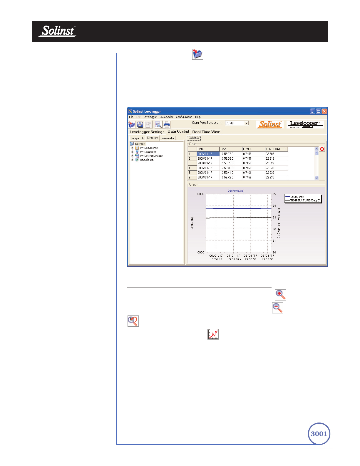
7 Data Control Window
(Downloading and Compensating Data)
Click the Data Control Tab from the Main Window, the Data Control window
will appear. From the Data Control window, the user can download data from
a Levelogger or Leveloader, display data in tabular or graphic form perform
data compensations and export.
FFiigguurree 77--11 DDaattaa CCoonnttrrooll WWiinn ddooww
7.1 Downloading Options
Click the Download icon from the Data Control window to download data
from the Levelogger. There are four options for downloading data. They are:
All Data, Append Data, Partial Download and Recover Previous Log. If the
users select All Data, the program will download all the data from the current
logging session of a Levelogger into a *.lev file. If the users select Append Data,
the program will append the data in the opened *.lev file from the Levelogger.
The opened *.lev file and the attached Levelogger should have the same serial
number and start time, otherwise an error will occur.
• Click the tab
to communicate with a
Levelogger.
• Click the tab
to communicate with a
Leveloader.
• Click the tab
to view the current file
pathway or to open a
specific file.
Note:
The first thing you
should do in this
window is click one
of the following tabs:

Levelogger User Guide - Software Version 3.2.3 or Higher
Page 28
FFiigguurree 77--33 FFiillee WWrriittee EErrrroorr MMeessssaaggee
If the user selects Partial Download, a Partial Download Selection Window will
open. The window shows the time stamp of the last reading in the logging session.
The users can select the number of hours before the data end time. Once the users
click OK, all the data within that time will be downloaded to a *.lev file.
If the user selects the Recover Previous Log, the software will try to recover the
data from the previous log session and download the data to a *lev file.
Once the data is downloaded from a Levelogger, it is automatically saved in a
temporary file.
Click the Save icon to save the data in a specific *.lev file. The default
directory for saved data is in the ‘Data’ folder. However, the default directory
for saved files can be changed by clicking the Configuration tab at the top of the
program window, selecting ‘Application Settings’ and inputting or navigating to
a different folder destination. If an error is experienced in saving your first data
file such as depicted in Fig 7-3, you may not have file writing privileges to the
default directory. It this case, create and set as the default file save folder, a new
Levelogger data folder within the My Documents folder and attempt the file save
procedure again.
FFiigguurree 77--22 PP aarrttiiaall DDoowwnnllooaadd WWiinnddooww
Page 29
Levelogger User Guide - Software Version 3.2.3 or Higher
Click the File Open icon to open a *.lev file. Multiple files can be opened
at the same time and are available for viewing by clicking the File Name Tab on
top of the data table. All the Levelogger settings and the channel information
effective during data collection are shown on the left of the window. Click the
Directory tab on the left of the window to show a directory list of the computer.
Click on the *.lev file from the directory list to open a specific *.lev file.
The Data Control window with the directory list is shown in Fig 7-4.
FFiigguurree 77--44 DDaattaa CCoonnttrrooll WWiinn ddooww wwiitthh DDiirreeccttoorryy LLiisstt
7.2 Graph Manipulation and Zoom Function
To perform the Zoom In function on the graph, click the button.
To perform a Zoom Out function on the graph click the button. Click the
button to undo all the zoom functions.
Click the Graph Option icon to open the Graph Option Dialog. The
Graph Dialog is shown in Figure 7.5.

Page 30
Levelogger User Guide - Software Version 3.2.3 or Higher
FFiigguurree 77--55 LLiinnee OOppttiioonn WWiinnddooww
FFiigguurree 77--66 TT iittllee aanndd AAxxiiss WWiinnddooww
The Line Option is used to adjust the style and colour of the line in the graph
for each channel. The user can also select the shape of the data marker or
remove the data marker.
The Title and Axis Option is used to enter the title of the graph and change the
Y axis label or user selected scale. Check the Best Fit box to enable the software
to determine the best fit scale. If the Best Fit box is not checked, the user has
to enter a maximum and minimum value of the selected channel. The X axis is
logging time.

Page 31
Levelogger User Guide - Software Version 3.2.3 or Higher
FFiigguurree 77--77 CChhaannnneell SSeelleeccttiioonn WWiinnddooww
FFiigguurree 77--88 DDaattaa CCoommppeennssaattiioonn WWiinnddooww FFiillee TTyyppee SSeelleeccttiioonn
The Channel Selection Option is used to control the visibility of each channel
on the graph. A check mark beside the channel name indicates that the channel
is visible on the graph. Click the Select All button to select all the channels.
7.3 Data Compensation
Click the Data Compensation icon to open the Data Compensation
Wizard. The Data Compensation Wizard is shown in Figure 8-8.
In the first window of the wizard, the user identifies the currently opened file
type. There are two file types: Barometric files (data that is retrieved from a
Barologger) and Submerged Levelogger files (data that is retrieved from
Levelogger Gold or Levelogger Junior. After the selection of the file type, click
Next and the Data Compensation selection window will open.
There are four data compensation options available: Barometric
Compensation, Manual Data Adjustment, Density Adjustment and
Barometric Efficiency.

Page 32
Levelogger User Guide - Software Version 3.2.3 or Higher
FFiigguurree 77--99 DDaattaa CCoommppeennssaattiioonn WWiinnddooww -- CCoommppeennssaattiioonn SSeelleeccttiioonn
• Manual Data Adjustment allows the user to enter a manual water
level measurement as a reference datum or field zero, which all
Levelogger water level readings can then be adjusted to. If the reference
datum is above water level (e.g. top of well casing), the datum must be
input as a negative value. If the reference datum is below water level
(e.g. sea level), a positive value is input. The date and time of
measurement of the reference datum must be recorded and input to
complete the adjustment. The program computes a correction factor
based on the time-stamped reference datum, and adjusts all the data in
the selected file after barometric, density, and other data compensations
are performed.
• Density Adjustment corrects the range of the level channel in the data
file based on a user input adjustment of fluid density.
• Barometric Efficiency Adjustment is used to proportionally adjust
Barologger data in relation to a particular Levelogger. Barometric
efficiency is often expressed as a percentage or proportion. The input
field is proportional and has a default value of 1.00. For more
information about Barometric Efficiency, see Section 11.1.3.
The barometric efficiency can be set from 0.01 to 3.00.
The compensated data will be saved in a new *.lev file. The default file
name will be the <Submerged Levelogger file name> with the word
<compensated> added to the file name prefix. Alternatively, the user
can name the compensated file. Do not change or delete the file
extension.
• Barometric Compensation requires the Barometric file and the
submerged Levelogger file and simply involves subtraction of the
barometric reading from the Levelogger reading. If there is an
inconsistency of the time stamp between the Barometric file and the
Submerged Levelogger file, a linear approximation on the barometric
data will be performed.

Page 33
Levelogger User Guide - Software Version 3.2.3 or Higher
FFiigguurree 88--11 RReeaall TTii mmee VViieeww WWiinnddooww
8 Real Time View Window
Click the Real Time View tab from the main software window and the Current
Readings Window will appear (Fig 8-1). The purpose of this window is to
provide on-screen measurement as data is being recorded by the connected
logger. The data is displayed in tabular and graphical format. All the channel
information and Levelogger settings are displayed in the bottom left window.
First, select a Non-Logged View Rate (middle left). This rate can be set
independently of the logging period of the Levelogger and does not interfere
with any logging taking place in the Levelogger itself. Real Time View readings
can be displayed as a graph or in tabular format. If one channel is not required,
it can be removed by unchecking the check box to the right of the data display.
If not displayed, it is not being recorded. Real Time View readings are being
recorded within the Levelogger Software and prior to closing the window, they
can be saved by exporting the data into a *.csv file, by choosing the file export
option.
To start the current readings, click the Start icon. Immediately the
readings will be displayed.
To take a reading at any specific time, click the button and that reading
will be added to the displayed data. To turn the Real Time View monitoring
off, decide if you want to save the data as described above, and simply click the
Real Time View Tab or the Levelogger Settings Tab.
Note:
Real Time View is
not available with
the Rainlogger.

Page 34
Levelogger User Guide - Software Version 3.2.3 or Higher
FFiigguurree 99--11 PP rriinntt PP rreevv iieeww WWiinnddooww
9 File Export and Print Function
Data can be exported in *.csv (comma separated value) file format by clicking
File > Export > Data. The *.csv file format is supported and can be imported
by most spreadsheet programs. Also, the data graph can be exported to a
*.bmp file or a *.wmf file by clicking File > Export > Graph.
The Logger Settings, data table and data graph can be printed. Click the Print
Preview Icon to open the Print Preview window. Figure 9-1 shows
the print preview of the Logger Settings. The Levelogger Settings are always
on the first page of the document. The data graph is on the second page of the
document and the rest of the document is data table.
Click the Print Icon to open the print dialog and print the document.

Page 35
Levelogger User Guide - Software Version 3.2.3 or Higher
FFiigguurree 1100--11
LLeevveell ooggggeerr TTrraa nnssdduucceerr
MMeeaassuurreemmeenntt LLiinnee aanndd
DDiimmeennssiioonn
10 Installation and Maintenance of Leveloggers
10.1 Installation
Many options exist for installation of the Levelogger, but essentially these
installation methods can be classified into two broad categories: free
suspended or fixed installations.
1. In free suspended installations, the Levelogger is hung via
suspension wire or Direct Read Cable from the well cap, or some
fixed tie-off location, at the well head.
2. In fixed installations the Levelogger is fixed in place by a
compression fitting, a clamping mechanism or simple metal straps.
Prior to commencing the discussion of installation techniques several
general points related to Levelogger installation should be made. First, it
is recommended that the Levelogger be installed in a vertical orientation.
However, inclined or horizontal installation is acceptable. The level
sensor in the Levelogger is indicated by the machined line about the body
of the logger just above the pressure access holes. The pressure
transducer is oriented in a plane normal to the long axis of the body and
detects pressure directed along the plane of the long axis (Fig 10-1).
In vertical orientations, the sensor detects pressure above the pressure
transducer line, where as in non-vertical orientations, the pressure zero
point is proportional to the angle of inclination.
Care should be taken to avoid dropping the Levelogger against a
hard surface. Further, the pressure transducer can be damaged if
the data logger is over-pressurized by submergence greater than its
level range. The Levelogger is warranted to pressures up to 150%
of its full scale level range.
Other important considerations when installing the Levelogger in
pressurized or intermittently pressurized locations such as pressure
vessels, pressurized pipes, pulse flow conditions, drop structures or near
hydraulics works, is to keep in mind the potential effect of water or steam
hammer and hydraulic jump. Water hammer is caused by an abrupt
alteration of flow direction resulting in pressure surges. Steam hammer
occurs when steam enters a cold pipe partially filled with water.
The hammer effect has the potential to significantly increase hydraulic
pressure possibly exposing the pressure sensor to pressures beyond its
maximum rating. Hydraulic jump is a phenomenon that occurs when
water is ‘lifted’ or ‘ramped’ by velocity or flow obstructions. Hydraulic
jump causes turbulence and creates non-representative head conditions
in the water column. Care should be taken to avoid logger installation at
points susceptible to hydraulic jump.
Note:
When using Direct
Read Cables, the
following maximum
lengths apply to the cable
according to which PC
Interface Cable is to be used:
• USB PC Interface Cable:
1,000 ft (300m)
• RS232 PC Interface Cable:
500 ft (150m)
• RS232 PC Interface Booster:
1650 ft (500m)
Measurement Line

Page 36
Diagram 1
Diagram 2
Diagram 3
Diagram 4
Coil 1
Coil 2
Coil 3
Coil 1
Coil 2
Coil 3
Wireline
Coil 3
Coil 1
Coil 2
Wireline
Coil 3
Coil 1
Coil 2
Wireline
FFiigguurree 1100--33 WWiirreelliinnee HHooookk
IInnssttaallllaattiioonn
Levelogger User Guide - Software Version 3.2.3 or Higher
10.1.1 Fr
ee Suspended Installations
Suspension Wire Installation
When installing using a suspension wire, the Levelogger is pre-programmed
and started using the software. It is then deployed using a suspension wire
connected to the installation cap of the Levelogger to the underside of a well
cap. The data is retrieved manually, by withdrawing the Levelogger, removing
the installation cap and attaching an Optical Reader directly to the data logger.
Data is downloaded to a desktop or laptop PC or by using a Leveloader Gold.
Solinst supplies stainless steel suspension wire assemblies including SS stranded
wire and hooks available in a variety of lengths from 50 ft (15 m) to +500 ft
(+150 m). Solinst also supplies a specially designed, tamper-proof, vented,
locking well cap known as the Enviro-Cap™ from which the Levelogger can be
suspended.
This type of installation is applicable to both submerged and barometric record
applications. Follow these steps to install the Levelogger using stranded cabling
and hooks:
1. Loop the cable through the coil 2 of the hook assembly, then wind the
looped strands several times around the hook shaft and pass through coil 1.
2. Pass coil 3 through the Enviro-Cap™ eyelet or Levelogger/Barologger eyelet
and snap coil 3 to the hook shaft.
3. If the Enviro-Cap™ is not used then some secure tie-off point should be used
or installed.
4. If installing a Barologger, ensure the suspension level is above the highest
expected water level.
5. When retrieving data and/or reprogramming the Levelogger, extract it from
the monitoring location, unthread the installation cap, interrogate and
re-suspend the unit rechecking the security of the wireline clamps each time.
FFiigguurree 1100--22
LLoocckkiinngg,, ttaammppeerr--pprrooooff
EEnnvviirr oo--CCaapp SStteepp 11
Tighten
(clockwise)
Loosen
(counterclockwise)
HOLD
HERE

Page 37
Levelogger User Guide - Software Version 3.2.3 or Higher
FFiigguurree 1100--44
DDiirreecctt RReeaadd AAsssseemmbbllyy CCoommppoonneennttss
Direct Read Cable Assembly Installation
When installing using a Direct Read Cable Assembly, the Levelogger can be
deployed before it is programmed and started with the software. The
Levelogger is installed using a Direct Read Cable to a Direct Read Wellhead,
where a PC Interface cable is connected allowing the Levelogger to
communicate with a desktop or laptop PC, or a Leveloader Gold.
The Direct Read Cable system is composed of the ordered length of Direct Read
Cable, the Direct Read Wellhead and the PC Interface Cable. The Direct Read
cable threads to the Levelogger, while the socket at the opposite end of the
Direct Read Cable fits into the specially designed Direct Read Wellhead. The PC
Interface Cable connects to the Direct Read socket at surface and to either a
USB or RS232 port on the PC (Fig.10-4). While use of the Direct Read
Wellhead is recommended and convenient, it is optional as long as a
satisfactorily secure alternative tie-off point is found for the Direct Read Cable.
Follow these steps to install a Direct Read Cable Assembly to the Levelogger:
1. Remove the installation cap from the Levelogger, align and connect the
optical socket (two glass ‘eyes’ using the alignment pin) of the Direct
Read cable to the Levelogger by threading the coupling onto the
Levelogger tightly.
2. The Levelogger and optical socket will fit through the hole in the Direct
Read wellhead. Use the eyelet at the bottom of the wellhead to securely
tie-off the cable and logger. Do not suspend the logger and cable from
the surface socket.
3. Remove the protective cap from the non-optical socket at the wellhead end
of the Direct Read cable, seat the socket in the Direct Read Wellhead and
align and thread it to the round socket of the PC Interface Cable.
4. Connect the USB or RS232 socket of the PC Interface Cable to the
USB or RS232 Com Port on your PC.
5. The plugged hole in the wellhead can be removed to provide an access
port for a water level meter probe.
10.1.2 Fixed Installations
Open Channel Installations
Open channel flow is flow defined as gravity flow in any stream, canal, ditch,
flume, or partially full pipe or tunnel not under pressure. It is different from
closed channel flow in which the closed channel is full and under pressure. This
section provides installation and monitoring advice in such open channels as
natural streams and engineered conduits such as concrete channels as well as
installation recommendations in monitoring water level in flow control structures
such as weirs, flumes, pipes and orifice discharge devices.
To ensure the integrity of monitoring data, it is vital to choose the monitoring
location with care. In natural channels, choose a location on the stream where
the flow is least turbulent without surcharging, yet representative of the
immediately upstream reach of the channel in slope and bottom surface
roughness. In streams or channels with deep or rapid flow, or of uneven or
slippery bottom materials, take extra care for your personal safety in installing

Levelogger User Guide - Software Version 3.2.3 or Higher
Page 38
equipment. Do not install equipment by attaching to structures that may
interfere with debris flow, threaten the stability of flow at that location or the
security of the equipment. When possible, install the Levelogger in a stilling well
device. The stilling well will protect the logger from floating debris and rock
saltation as well as dampen the effects of surface waves or turbulence. If a stilling
well cannot be used and the logger must be affixed to an anchor structure
instream such as a concrete slab or large stable boulder, consider protecting the
logger from floating debris and rock saltation by placing it inside a short
perforated section of protective 1” dia. pipe. Avoid monitoring in the vicinity of
flow obstacles that can cause hydraulic jump. In pipes, the logger should be
located at least 2 – 4 pipe diameters down and upstream of pipe turns,
junctions, inlets, outlets, turbulent joints or valves. Place the logger upstream of
zones potentially subject to surcharging. Always bear in mind that the logger
does not have to be at the deepest point in the stream or at the bottom of the
pipe, it need only be located in the safest location within the stream/pipe profile
just below the lowest anticipated water line. In this case use an offset value or
the Reference Datum adjustment to compensate the data for the level offset.
This Section discusses flow in open channels determined by one of the following
methods: Area-Velocity, Slope-Hydraulic radius and Hydraulic structure(s).
Using the Area-Velocity method the Levelogger provides readings of the
head of water above the pressure transducer. The practitioner will use the water
depth to determine the cross-sectional area of water, then the water velocity to
ultimately derive flow:
Flow = Area x Velocity
The cross-sectional area of water in natural channels is most commonly
determined by surveying the shape of the channel bottom at the monitoring
station. In circular pipes the wetted area can be determined by using a section
of a circle equation and in other engineered channels, by determining the
channel geometry. Either water head will be related to area by using and
equation, where head is the only variable, or the Head: Area information is
compiled in a Look-up table. The water velocity can be determined in a number
of ways, by estimation taking into account the channel geometry, area and
surface roughness, by spot measurement in which the stream is velocity profiled
both vertically and across its cross-sectional area to develop a rating curve, or
by deployment of a logging velocity meter that can accurately characterize the
velocity over the cross-sectional area. Together the area multiplied by average
velocity to derive flow.

Page 39
Where: Q = Flow rate
K = Constant dependent on units used
A = Cross sectional area of low
R = Hydraulic radius (cross sectional area divided by the
wetted perimeter)
S = Slope of the hydraulic gradient
n = Manning’s roughness coefficient
Q =
KAR
n
2
_
3
1
_
2
S
Hydraulic structures are among the most common and reliable means
of measuring flow. Four types of hydraulic structures and the methods
used to measure them are discussed here: weirs, flumes, pipes and orifice
discharge devices.
Levelogger User Guide - Software Version 3.2.3 or Higher
In the Slope-Hydraulic radius method, techniques like the Manning
formula or variations such as Lanfear and Coll or Chezcy’s equations are
used to estimate flow based on changes to the cross sectional area and
wetted perimeter. The cross sectional area and wetted perimeter must be
predetermined and are proportional to head. The Manning formula:

Page 40
Levelogger User Guide - Software Version 3.2.3 or Higher
Installation at W
eirs
Weirs are very common and reliable flow control and measurement structures.
A wide variety of weir types have been designed and their flow characterized in
discharge equations. The most common weirs are sharp-crested rectangular,
V-notch, trapezoidal (Cipolletti) and compound weirs combining elements of
two or more of these types. Other special weir configurations are designed to
create a specific type of relationship between head and flow rate. The Sutro
weir creates a hydraulic condition where discharge is directly proportional to
head. The approximate linear weir creates a hydraulic condition where the
head: discharge relationship is linear. Other weirs such as the Poebing and
Approximate exponential weir have an exponential relationship between head
and discharge. However, no weir design is more common and better
understood than the rectangular, V-notch or trapezoidal configurations.
From a monitoring point of view it is extremely important to place the pressure
transducer at the appropriate location at the weir. Figure 10-5 illustrates the
appropriate location of the pressure transducer upstream of the weir crest and
the draw-down zone.
3-4 H
2-3 H
Channel Floor
FFiigguurree 1100--55 SShhaarrpp CCrreesstteedd WWeeiirr
The formuli for the three most common weir designs are:
V-Notch: Q = KH
2.5
Rectangular:
a. Suppressed (no end contractions) : Q = KLH
1.5
b. Contracted (with end contractions): Q = K(L - 0.2H) H
1.5
Trapezoidal or Cipolletti: Q = KLH
1.5
Where: Q = Flow rate
H = Head on the weir
L = Crest length of the weir
K = Constant dependent on units
Location of
Measurement Point
Drawdown
Crest
HH
Ventilation
3-4 H
3-4 H
2-3 H
2-3 H
Weir Plate
Channel Floor
Channel Floor

Page 41
Levelogger User Guide - Software Version 3.2.3 or Higher
K values for V-notch weirs for metric of US Customary units vary with the
V-notch angle and can be found in hydraulic texts. K values for the sharpcrested rectangular weirs and the Cipolletti weir, in which the slope of the
trapezoid is 4:1, are provided in Table 10-1
CFS GPM MGD L/s
m3/hr
Unit of L & H
ft ft ft m m
K suppressed & contracted
3.33 1495 2.152 1838 6618
K Cipolletti trapezoidal
3.37 1511 2.176 1859 6692
K California pipe method
8.69 3900 5.62 4680 16900
TTaabbllee 1100--11 CCoonnssttaanntt VVaalluuee ss ffoorr RReeccttaanngguullaarr WWiieerrss
Installation in Flumes
After weirs, flumes are the most common hydraulic control structures and use
flow restriction followed by flow expansion so that flow rate may be determined
by head measurement at a specific point in the flume. In general flumes are
used where weirs are not feasible due to inadequate channel slope or channel
space footprint restrictions. Flumes are grouped into one of three categories
based on the Froude number of flow set up by the flume. The Froude number
is the ratio Inertia : Gravity. If the Froude number is unity, the flume flow is
considered critical. When the Froude number is less than unity, sub-critical
(gravity predominates) and when greater than unity, supercritical (inertia
predominates). Most flumes are designed for critical or supercritical flow.
Critical flow flumes typically use width reduction to set up the critical flow
conditions. Supercritical flow flumes utilize a sloping bed, bed drop and or width
reduction to create supercritical conditions from the converging section,
through the throat to the diverging section. The most common flume types are
Parshall, Trapezoidal, Palmer-Bowlus, Leopold-Lagco, USDA Soil
Conservation Service HS, H and HL flumes as well as Cutthroat, British
rectangular and San Dimas flumes.
As in weirs, the head measuring point(s) in flumes is very specific. Figure 10-6
illustrates the recommended upstream free flow head monitoring point for a
Parshall flume. This point is defined as upstream of the start of the throat, 2/3
the total length of the converging section. The head vs flow rate equation for
free flow via a Parshall flume is:
Where: Q = Flow rate
H = Head measured at point 2/3 A
n = Constant power, dependent on throat width
K = Constant dependent on throat width and units
Q = KH
n

Page 42
Levelogger User Guide - Software Version 3.2.3 or Higher
FFiigguurree 1100--66 PPaarrsshhaallll FFlluu mmee
The Parshall flume is characterized as supercritical by width reduction and drop
in bed. An alternative head measurement is in the throat upstream of the zone
of submerged flow. Care must be taken when using head measurement in the
throat that backwater or surcharging effects in the diverging section during
periods of higher flow do not reach the throat monitoring point.
The California Pipe Method
The California pipe method of flow measurement is for use with circular pipe,
partially filled and horizontal for at least 6 pipe diameters prior to pipe
discharge into air. Water should not enter the horizontal section at an excessive
rate and if flows create near pipe-full conditions, a vent hole should be installed
several pipe diameters upstream of the outfall. To determine pipe discharge
using head at the outfall the California pipe method may be written as:
Where: Q = Flow rate
H = Head of liquid at pipe outlet
d = Pipe diameter
K = Constant dependent on units
Q = Kd
0.6 H1.88
A - Length of converging section
2/3 A
Location of Monitoring Points
Submerged
Flow
Free flow

Levelogger User Guide - Software Version 3.2.3 or Higher
Page 43
Orifice Dischar
ge Monitoring
Discharge through orifices such as in a Hickenbottom perforated riser is a
common water detention and flow control approach. The Hickenbottom device
typically uses a series of circular holes drilled both around the circumference
and along the vertical length of a section of riser pipe connected via an elbow
joint to a lateral discharge pipe. Hickenbottom devices are commonly used to
detain stormwater in ponds, wetlands, ditches, swales or depressions at the
Hickenbottom riser to reduce downstream erosion and prolong the settling
period for suspended solids prior to discharge thereby improving water quality.
Hickenbottom devices enable the practitioner to derive discharge rate by head
measurement outside the structure. Discharge from a Hickenbottom structure
can be calculated as the iteration of individual single orifice discharge equations.
A typical orifice equation is derived from Bernoulli’s equation and can be
written as follows for metric units:
Where: Q = Orifice discharge in m
3
/sec
C = The discharge coefficient (CcCv≈ 0.647), where Cc,
the coefficient of contraction, for a sharp-edged
orifice is ≈ 0.66 and Cv, the coefficient of velocity
through the orifice is ≈ 0.98.
A = Orifice area in m
2
g = Acceleration due to gravity (9.81 m/sec2)
h = Head in m of water above the orifice
Q = CA(2gh)
0.5
Artesian Monitoring
Monitoring of artesian conditions in which the piezometric surface is above
ground surface or more particularly above the top of well casing elevation using
Leveloggers can be quite straight forward. Three artesian scenarios are
discussed: a) continuous artesian conditions where i) freezing is not a concern,
ii) or where freezing is a concern and b) intermittently artesian conditions.
Continuous artesian conditions infer that the piezometric surface never drops
below the level the ground surface or particularly the top of casing elevation and
the casing is sealed with a sealed wellhead. In this case, where freezing is not a
concern, the Levelogger need only be installed in the wellhead itself by means
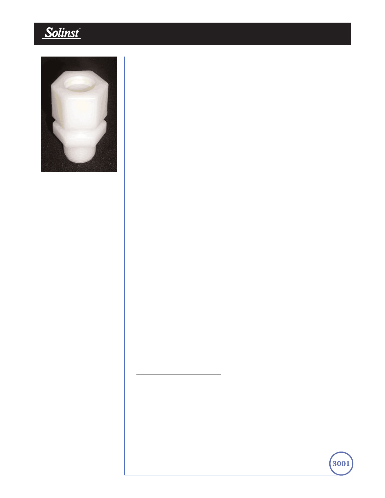
of a large compression fitting as illustrated in Figure 10.7. Solinst can supply a
7/8” nylon compression fitting for this purpose. First, a 7/8” NPT hole is
tapped into the wellhead, then the base of the compression fitting is threaded
into the hole and the threads sealed. The collar and ferrule are slid on the
Levelogger just above the transducer measurement line (collar below ferrule),
the logger inserted in the base and the nut slide down over the body of the
logger. The nut is tightened and threads sealed to form a hydraulic seal against
the body of the Levelogger leaving the upper portion of the Levelogger and cap
exposed above the compression fitting. The user can communicate with the
logger simply by removing the logger cap and attaching the Optical reader.
Ensure that the logger and sealed wellhead are enclosed within an outer
protective well cap or enclosure.
When freezing is a concern in a continuous artesian well, the well is typically
sealed below the frost line with a packer. Again, Solinst can build specially
adapted mechanical packers for this purpose. The special packer is typically
built on 1 – 2” PVC pipe that extends from below the frost line to the wellhead
and is actuated at the wellhead by turning a threaded tube that runs within the
pipe. Direct Read cable for communication with the Levelogger is built into the
packer. The Direct read cable runs through the threaded tube and sealed by use
of a small compression fitting that tightens onto the Direct Read cable. When
installing the Levelogger is threaded to the Direct Read cable and
the Levelogger and packer assembly lowered into the well. When in place, the
packer is actuated, the well sealed and standing water in the well above
the packer is evacuated.
Intermittently artesian conditions imply that the peizometric surface fluctuates
above and below ground surface or particularly the top of casing elevation.
The methods described above can be used in intermittently artesian conditions.
However, a third option exists in that whereby the 7/8” nylon compression
fitting described above can be slid nut first, ferrule above collar, over the optical
connector and length of the Direct Read cable and tightened to the underside
of the surface connector. The Levelogger attached to the Optical connector and
cable can be inserted through a 7/8” NPT hole tapped into the sealed wellhead
as described above and the threaded base of the fitting threaded into the tapped
hole in the sealed wellhead. One caveat to this installation is that we
recommend an eyelet be installed on the underside of the sealed wellhead and
the Direct Read cable be suspended from the eyelet instead of suspending free
from the surface connector.
When conducting artesian monitoring with Leveloggers a number of
considerations must be kept in mind. First, ensure that the maximum hydraulic
pressure the Levelogger will encounter within the well at its installation point
will not exceed the hydraulic range of the logger. Second, artesian conditions
do not preclude the necessity for barometric compensation of Levelogger data.
Artesian conditions are caused by aquacludes forming confined aquifers.
Confined aquifers, while not acted on by barometric pressure to the same
extent as unconfined aquifers, are typically subject to barometric pressure at
some barometric efficiency (See Section 10.1.3). Finally, bear in mind that the
total pressure and subsequent water column equivalent depth measured by the
Levelogger after barometric compensation may not represent the actual water
level within the artesian well. Sealed intermittent artesian wells can be
pressurized when artesian, but can also be de-pressurized when non artesian.
The Levelogger’s reading after barometric compensation represent the height
of the piezometric surface.
V
acuum/ V
apor Monitoring
Vacuum/Vapor monitoring is conducted to determine the explosive potential of
the vadose zone, to assess the volatilization rate of hydrocarbon contaminants
or to determine hydrocarbon Vapor chemical concentrations. Vacuum
monitoring is usually conducted by first installing pressure transducers such as
the Levelogger in monitoring wells and then shutting-in or sealing those wells
to the atmosphere with pressure sealed wellheads. Air is pumped out from an
extraction well amongst the cluster or matrix of monitoring wells, theoretically
dropping air pressure in the vicinity of the extraction well. For short-term tests
in which data is not required during the extraction event, the Leveloggers can
be programmed and simply suspended from hooks or eyelets on the
Levelogger User Guide - Software Version 3.2.3 or Higher
Page 44
FFiigguurree 1100--77
77//88”” NNyylloonn CCoommpprreessssiioo nn FFiittttiinngg
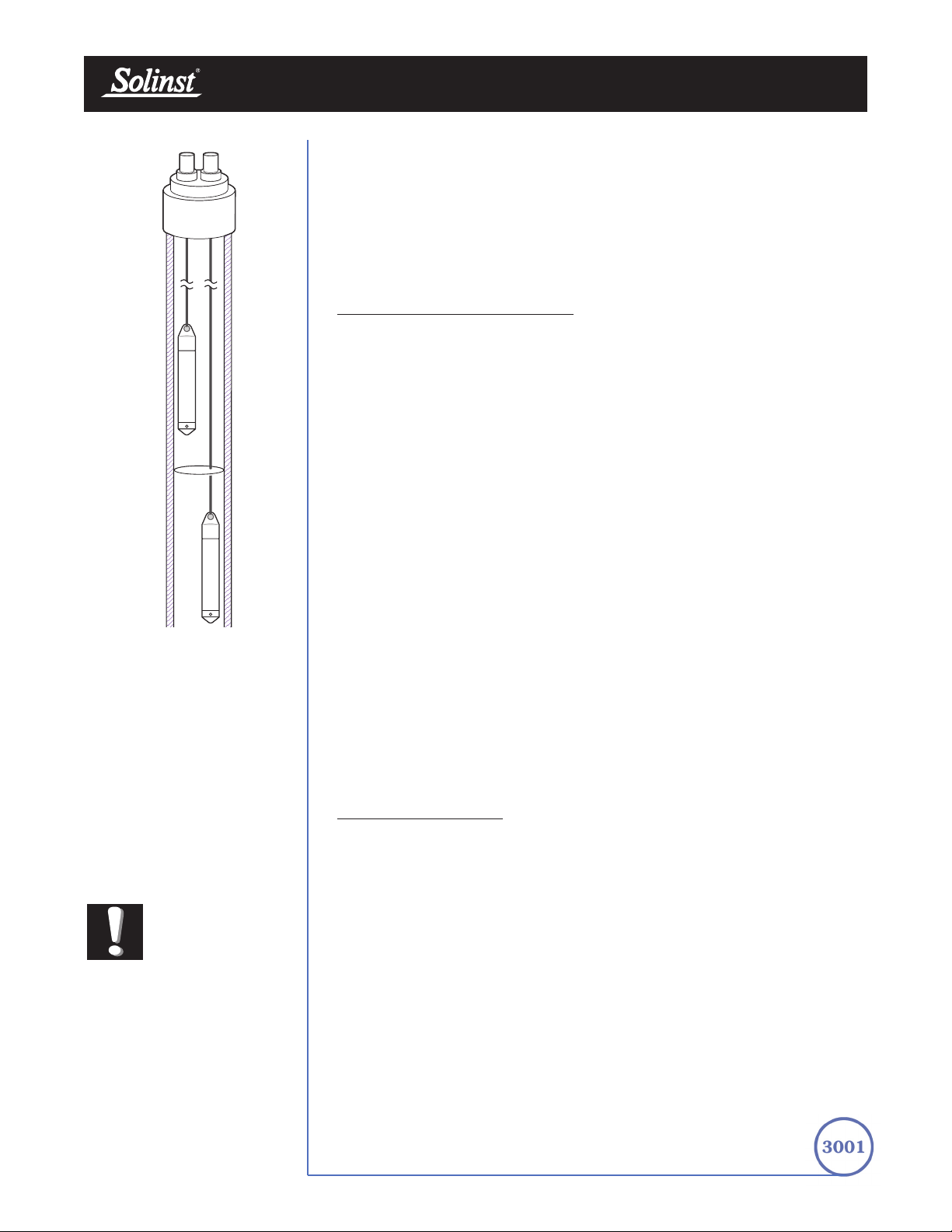
Levelogger User Guide - Software Version 3.2.3 or Higher
Page 45
underside of the sealed wellheads, the test run and the data collected at the end
of the test by extraction and downloading of the loggers. However, if ongoing
data from the Leveloggers is required during the extraction event, the loggers
must be installed in a manner similar to the artesian monitoring scenarios
described in previously in this section. Leveloggers or Barologgers can be used
to monitor the drop in pressure. However, if using Barologgers in the well
headspace ensure that adequate range exists above net barometric pressure to
monitor the anticipated drop in pressure.
10.1.3 Barologger Installation
The Barologger is a Levelogger with a small range of 4.92 ft (1.5 m) adequate
to monitor the fluctuations that occur in barometric pressure. The Barologger’s
readings are used to barometrically compensate Levelogger readings. Typically,
Barologger readings range from 1 – 3.3 ft (30 – 100 cm) when the Barologger
is programmed with its operating altitude. Failure to input the correct altitude
with result in incorrect readings and may cause the pressure transducer to go
out of range. It is strongly recommended that the altitude input be accurate
to ≤10 m. When the Barologger is programmed at its operating altitude, its
readings can be used to directly compensate for barometric pressure, the
readings of any Levelogger programmed at the Levelogger’s operating altitude.
As a rule or thumb, a Barologger can be used to compensate all the
Leveloggers in a 20 mile (30 km) radius.
To monitor barometric pressure correctly, the Barologger should never be
submerged. In well installations, it is recommended that the Barologger be
suspended in one of the monitored wells above the high water point (Figure 9-8).
For best reading accuracy, the Barologger should be installed in a similar
thermal environment to that of the Levelogger. In groundwater wells, the
Barologger should be suspended beyond the frost line and deep enough to
avoid large temperature fluctuations. In surface water applications, the
Barologger is best deployed in a dry well – a well embedded in the bottom of
the water body, but sealed at the base from water entry and vented to the
atmosphere. If a dry well cannot be installed, the Barologger can be installed on
a float in the stilling well. Further information on the Barologger and barometric
pressure can be found in Section 11.
Bar
ometric Efficiency
The influence of barometric pressure on a groundwater surface can follow three
scenarios. In confined aquifers with capillary or vadose head space, increased
atmospheric pressure can tighten the pore spaces in the overlying soil and
produce a capillary effect as the water level rises in response to having nowhere
else to go but up. Second, some deeper aquifer systems can be quite
barometrically isolated from the relatively small change in level that barometric
influences can produce. The third scenario occurs in an unconfined aquifer,
with high barometric efficiency, in which a barometric pressure change results
in an equivalent or highly proportional drop or rise in groundwater pressure. In
essence, depending on the aquifer type and depth, increased barometric
pressure can result in either increased, static or decreased water levels.
Barometric efficiency, the relationship of a barometric change on groundwater
pressure, in confined aquifers generally ranges from 20 to 75%, whereas in
unconfined aquifers the efficiency can range from 80 - 100%.
FFiigguurree 1100--88 LLeevveellooggggeerr
aanndd BBaarroollooggggeerr iinn WWeellll
LLeevveellooggggeerr
BBaarroolloogggg eerr
Note:
The
Barologger
Gold should not
be used to
monitor water, as the
internal mathematics are
based on air pressure rather
than water pressure.

A second important element of Barometric efficiency is time lag – the time
differential between a unit change in barometric at the surface to the time of
transmission of that change to the aquifer. Calculating general barometric
efficiency should not be done on a single barometric event, but rather on a
statistically significant number of events. As a result, it may take a month or
more of submerged Levelogger and Barologger data to determine barometric
efficiency and time lag. As Barometric pressure fluctuates over time in excess
of 60 cm water column equivalent pressure and as barometric efficiency can be
such an important factor in accurately monitoring groundwater levels, it is vital
that barometric compensation of the Levelogger data be performed.
Barometric efficiency and time lag cannot be determined with vented pressure
transducers in which barometric efficiency is assumed to be 100% no time lag.
The inherent error these assumptions can cause in the incumbent data can be
quite significant. The absolute pressure method used in the Levelogger and
Barologger provide the user with the data necessary to determine barometric
efficiency. If a barometric efficiency value has been determined from the
Levelogger and Barologger data, that value can be applied to Barologger data
in the Compensation Wizard. Application of this feature can produce
net groundwater level data of an accuracy that cannot be produced by
vented transducers.
Wells puncturing an aquifer have a negligible to non-existent effect on directly
transmitting barometric changes to the larger aquifer. Barometric pressure is
transmitted through overlying layers. To obtain the best and most accurate
long term water level readings from Leveloggers, the user must first
understand how the Levelogger calculates a depth of water above the
transducer and second whether barometric efficiency should be considered in
barometric compensation.
Levelogger User Guide - Software Version 3.2.3 or Higher
Page 46

Levelogger User Guide - Software Version 3.2.3 or Higher
Page 47
10.1.4 Installation in Extreme Thermal and Marine Environments
Freezing or High Temperature Conditions
Levelogger installation at submerged depths that may be at risk of freezing
during the monitoring session is not recommended without taking adequate
precautions to avoid transducer damage. When water freezes it expands
approximately 9% by volume. 9% expansion can equate to extreme pressure
as demonstrated in Example 10.1. Therefore, solid freezing has the potential
to damage the pressure transducer, which is rated to withstand up to 150% of
its depth fluctuation range. Pressures beyond this threshold may damage the
transducer. With certain precautions, the Levelogger can be used in freezing
liquid environments. If monitoring shallow water bodies or groundwater zones
susceptible to freezing, the easiest way to avoid transducer damage is to lower
the transducer to a point in the water column below the frost line or ice
formation depth. In water bodies such as shallow streams, wetlands or ponds
where freezing may penetrate to the bottom, install the Levelogger in a vented
stilling well imbedded into the bottom of the water body beyond the frost line.
In cases where the above noted precautions cannot be taken and the
Levelogger must be installed in the freezing zone, it is recommended that the
logger be placed inside two elongated silicon, rubber or latex balloons, the
balloons be filled with a non-toxic, non-corrosive anti-freeze solution and sealed
(Figure 10-9). Place the balloons in a section of perforated, 1.25" (30 mm) ID
pipe and install the logger in the monitored water. The antifreeze solution will
protect the Levelogger from ice expansion at the pressure transducer, yet
transmit any pressure fluctuations that occur. Please note that a similar
installation protection can be used when the Levelogger is monitoring liquids
which are incompatible with its wetted materials. The operating temperature
range for Leveloggers is -20° - 80°C (-4° - 180°F). At the opposite end of the
thermal scale, exposing the Levelogger to temperatures beyond 80°C may
damage the thermistor and otherwise affect the Levelogger.
1100--99
IInnssttaallllaattiioonn iinn FFrreeeezziinngg LLiiqquuii dd
Example 10.1 Solid Freezing Effects
The pressure exerted by the physical expansion or ice crystallization process
on a retaining or enclosing contact surface is related to the temperature
gradient over which the process occurs. For example, liquid freezing at -22ºC,
can create expansion pressures of 22 kg/cm2 or 313 psi or the equivalent of
721ft or 220m water column depth.

Levelogger User Guide - Software Version 3.2.3 or Higher
Page 48
Marine or Brackish Installations
When installing the Levelogger in salt or brackish water or in a liquid having a
specific gravity (density) different than fresh water, the density difference is
compensated for by checking the Density Adjustment checkbox in the
Levelogger Settings window and inputting the density of the monitored fluid.
See Section 5.1 for details in compensating the Levelogger for fluid density
differences.
The LT Levelogger can be used for monitoring in salt or brackish water.
However, continuous use of the first generation stainless steel body LTC
Levelogger or LT Levelogger in salt or brackish water is not recommended, as
the salt or other pollutants may cause pitting which can lead to perforation of
the Levelogger’s casing. To minimize this effect, regularly lift the Levelogger
from the liquid; within seconds a thin protective layer will be formed by
oxidation. Again, this precaution applies to the first generation stainless steel
LTC and the LT Levelogger. If using an LT Levelogger in a continuous
salt/brackish monitoring scenario, the stainless steel body of the data logger
can be protected in a manner similar to the freezing protection method
described in Section 10.1.4. The LT can be placed in balloons and the balloons
filled with non-corrosive/ non-toxic fluid. As pressure changes, the fluid
encasing the loggers will transmit the pressure differential to the logger’s
pressure transducer. Care must be taken in the selection of the balloon material
or filling fluid such that the balloon material prevents diffusion of salts across
the concentration gradient or that the filling fluid is comprised of polymeric
molecules too large to diffuse out of the balloon material.

10.1.5 Refer
ences
American Sigma, 2001. An Introduction to Open-channel Flow
Measurement Technology. American Sigma, Loveland, CO
Bedient, P.B. and Huber, W.C. 1988. Hydrology and floodplain analysis.
Addison-Wesley Publishing Co., Don Mills, ON
Chow, T.V., 1959. Open-channel hydraulics. McGraw-Hill Book Co, New
York
Daugherty, R.L., Franzini, J.G and Finnemore, E.J. 1985. Fluid
mechanics with engineering applications. McGraw-Hill, New York
Ferguson, B. and Debo, T.N. 1990. On-site stormwater management.
Van Nostrand Reinhold, New York
Freeze, R.A., and Cherry, J.A. 1979. Groundwater. Prentice-Hall Inc.,
Englewood, NJ
Grant, M.D. and Dawson, B.D., 1997. Isco open channel flow
measurement handbook. (5th Ed.) Isco, Lincoln, NE
ISO 4559-1983, 1983. Liquid flow measurement in open channels –
rectangular, trapezoidal and U-shaped flumes. ISO, Geneva
Kilpatrick, F.A., 1965. Use of flumes in measuring discharge at gaging
stations. Surface Water Techniques, Book 1, USGS, US DOI,
Washington, DC
Kulin, G. and Compton, P.R., 1975. A guide to methods and standards
for the measurement of water flow. National Technical Information
Service, Springfield, VA
Lanfear, K.J. and Coll, J.J., 1978. Modifying Manning’s equation for
flow rate estimates. Water & Sewage Works (March)
Manning, R., 1891. On the flow of water in open channels and pipes.
Transactions of Civil Engineers of Ireland, V20(1891):161-207 and
V24(1895):179-207
Parshall, R.L. 1950. Measuring water in irrigation channels with Parshall
flumes and small weirs. US SCS Circular 843 (May)
US DOI 1967. Water Measurement manual. US Dept of Interior, Bureau of
Reclamation, Denver, CO
Vanleer, B.R., 1924. The California Pipe Method of water management.
Engineering News record (Aug 3/22, Aug 21/24)
Viessman, W. and Lewis, G.L. 1996. Introduction to Hydrology, (4th
Ed). Harper Collins College Publishers, New York
Wilson, E.M. 1990. Engineering Hydrology. MacMillan Education Ltd.,
London
Levelogger User Guide - Software Version 3.2.3 or Higher
Page 49

10.2 Levelogger Maintenance
Levelogger maintenance consists of cleaning the outside stainless steel casing,
the circulation holes and the optical infrared eyes. The required frequency of
cleaning is dependent on several aspects of the monitored water quality.
In freshwater with good to excellent water quality, the Levelogger cleaning
requirements will be very minimal; amounting to a seasonal or even annual
maintenance inspection. In most cases cleaning can be accomplished by rinsing
the Levelogger and using mild, non-residual, non-abrasive household cleaners
using a very soft-plastic, bristled, pipe-cleaner type brush. Do not insert any
object through the circulation holes at the sensor end of the Levelogger.
In some cases simple cleaners are insufficient to properly clean the Levelogger.
Several commonly occurring water conditions require specific maintenance
methods, these include hard water, high suspended solids loading, biological or
chemical fouling and salt or brackish water conditions.
Hard water monitoring can result in the precipitation of calcium and
magnesium deposits on the pressure transducer as well as other components
of the Levelogger. These deposits can be safely dissolved using a diluted
solution (typically ≤ 10% strength) of acetic or phosphoric acid.
Commercially available products for dissolving hard water scaling are also
available and can be used if designed for household use. Some industrial
strength hard water scaling removers are much higher strength and are not
recommended for cleaning the Levelogger.
High suspended solids load may block the circulation ports or clog the
internal pressure cell of the Levelogger. The potential clogging effect of solids
deposition can be minimized by placing the Levelogger in zones of flow.
To remove solids build up, rinse the Levelogger under a low flow of tap water
until particles have been washed away.
Bacteriological or chemical fouling can be an important consideration in
many ground and surface water monitoring projects. Sessile bacteria will often
utilize installed instrumentation as an attachment substrate. Chemical deposit
can be the result of electrical charge differential between the instrumentation of
the monitored liquid or the result of biological or algal activity. Both forms of
fouling can result in difficult to remove deposits on the Levelogger transducer,
the conductivity wires and the Levelogger casing. To remove fouling use a
diluted (≤ 10%) solution of sulfuric acid. Persistent material may require soaking
for several hours.
Levelogger User Guide - Software Version 3.2.3 or Higher
Page 50

11 Manual Barometric Compensation
This section describes how to perform manual barometric compensation on
Levelogger data files when a Barologger was not dedicated as a barometric
recorder. This section describes available sources of barometric record,
conversion factors for common barometric units to water column equivalent
and how to perform the compensation in spreadsheet formats using available
barometric information. Finally, this section describes the most accurate and
representative methods of obtaining barometric data and performing
barometric compensation on submerged Levelogger data.
For short term tests during which the barometric pressure varies insignificantly,
the collection of continuous barometric data may be unnecessary. In this event,
take a reading from an open air exposed Levelogger prior to running the short
term test and record this level. This level represents the barometric pressure.
Similarly, at the end of your test, take another barometric reading and record
this measurement. After the submerged Levelogger data has been exported to
a spreadsheet program compensate your submerged Levelogger data files for
barometric pressure. If no appreciable change in barometric reading occurred,
you may write in the first cell of a new column a simple calculation that
subtracts the water column equivalent of your barometric reading from the
submerged data file, then copy and paste this calculation to all the cells in that
new column. The new column will represent the barometrically compensated
liquid level.
Barometric data can be collected on site using a recording barometer or from
a local weather station. If setting up the barometer, set the recording interval to
that of the Levelogger sampling interval or some multiple of the Levelogger
interval. To compensate submerged Levelogger data using barometric data
collected from an on site barometric data logger or a nearby weather station
several steps must be taken:
1. Export both the Levelogger data file and the barometric file to a
spreadsheet.
2. In the spreadsheet, convert the barometric data column from its
barometric measurement units (typically atm, mm Hg, psi, mb or kPa)
to feet or meters of water column equivalent using the conversion factors
in Table 11-1.
Levelogger User Guide - Software Version 3.2.3 or Higher
Page 51

3. Then write another calculation in another column to subtract the
Levelogger’s pressure zero point offset value from the converted
barometric data. The Levelogger’s zero point offset is 31.17 ft (9.5 m)
of water column less an altitude correction. 31.17 ft (9.5 m) is the lowest
expected barometric pressure at mean sea level. As elevation increases
above mean sea level, the lowest expected barometric pressure
decreases at a rate of approximately 1.21/1000 ft or m (altitude/826)
of altitude. Therefore the Leveloggers barometric pressure offset at
1500 ft elevation will be:
(Zero Point Offset at MSL) – (Altitude Correction) =
(Elevation-Corrected Zero Point Offset)
(31.17) – (1500/826) = 29.35 ft
The Levelogger Gold automatically adjusts to this elevation-corrected
zero point offset when the altitude is input into the programming setup
accurately. The altitude used to calculate the altitude correction MUST
be the altitude input in the altitude field of the Levelogger setup.
Therefore, if the altitude at time of the above Levelogger setup was
uncertain and an altitude value of 1200 ft was input in the altitude field,
then 1200 ft must be used to calculate the elevation-corrected zero point
offset. The elevation-corrected zero point offset is subtracted from the
barometric pressure expressed in water column equivalent to determine
the amount of barometric pressure the Levelogger is recording above its
elevation-corrected barometric pressure zero offset.
For previous Levelogger versions use an altitude correction of 1:1000.
4. This net barometric pressure expressed as water column equivalent is
the amount of barometric pressure the Levelogger is currently sensing.
This value is then subtracted from the Levelogger submerged data file.
Example 11.1 provide a case study of how manual barometric
compensation is performed.
Levelogger User Guide - Software Version 3.2.3 or Higher
Page 52
Table 12-1
Common barometric units to water column equivalent
Barometric unit
W
ater column
equivalent (ft)
W
ater column
equivalent (m)
1 psi
1 atm
1 kPa
1 mm - Hg
1 in - Hg
1 mb
2.3108
33.959
0.3352
0.04469
1.1330
0.03352
0.7043
10.351
0.1022
0.01362
0.3453
0.01022
TTaabbllee 1111--11 CCoommmmoonn BBaarroommeettrriicc UUnniittss ttoo WWaatteerr ccoolluummnn EEqquuiivvaalleenntt CCoonn vveerr ssiioonnss
Levelogger User Guide - Software Version 3.2.3 or Higher
Page 53
EXAMPLE 11.1
A Levelogger Gold is monitoring at 1625 m (5332 ft) AMSL in Colorado. A recording
barometer is also logging at the same sample interval in barometric units of psi. If we
examine how to perform manual barometric compensation on Levelogger Gold data
from a particular reading time, we will understand how to perform the manual
barometric compensation process. The Levelogger’s altitude field was set at the
accurate elevation of 1625 m and the level reading at the start of submerged data
collection was 10.25 ft. The barometric data reading at that time was 12.18 psia which
converts to a water column equivalent of 28.15 ft.
The Levelogger’s elevation-corrected barometric pressure offset value was:
31.17 ft – (5332/826) ft = 24.715 ft
This value is subtracted from the recording barometer’s reading to obtain the
amount of barometric pressure the Levelogger is sensing:
28.15 ft – 24.715 ft = 3.43 ft
Therefore, at the time of these readings the Levelogger’s level reading was
being influenced by 3.43 ft of effective barometric pressure. The actual water
level above the Levelogger therefore is the total level measurement it records
less the effective barometric pressure it sensed:
10.25 ft – 3.43 ft = Actual Water Level
= 6.81 ft of Water Level
When analyzing barometric data it is important to keep in mind that storm
events commonly reduce total atmospheric pressure by about 1.7% from
pre-existing high pressure conditions. 1.7% converts to approximately 0.6 ft or
0.2 m of water level equivalent barometric fluctuation.
The most accurate and reliable method of obtaining representative barometric
compensation of water level readings is to employ an accurate surface
barometric recorder (ie. the Barologger). The traditional convention has been
to use a vent tube reaching from the surface to the transducer. This vent tube
terminates behind the transducer diaphragm, theoretically filtering barometric
effects on level readings from total pressure. After much experience with
erroneous barometric compensation due to crimped, damp, wet and cut tubing,
unacceptably slow response to small barometric change and many situations
where barometric compensation was not required, we decided vented tubing
did not offer the level of integrity in barometric compensation our clients
deserved. A recording barometer does and will provide the data necessary to
access barometric compensation requirements.
Vented tubing has been used in the past for several reasons. One it was a
cheap, low tech method of balancing out the effect of barometric pressure on
a monitored water surface. Second, when the tubing is cared for, inspected and
tested for failure regularly, it responds reasonably well to steep barometric
gradients such as when a large scale atmospheric front moves across the
surface. The seldom discussed problem is that the response time to the much
more common incremental barometric change is unacceptable. The vented
tubing often leaked or its connection to the pressure probe leaked, causing the
transducer to fail and experience irreparable damage. Some manufacturers,
recognizing the inherent inferiority of passive venting, have adopted a method
of automatic vent tube testing whereby a small vacuum pump at the surface

12 Diagnostics Utility
The Levelogger Gold Diagnostics Utility can be used for troubleshooting the
Levelogger Gold and obtaining information about that Levelogger that can assist
the Solinst Technical Support representative to identify and fix any problems
you may encounter with your Levelogger Gold.
The utility can be used to read Levelogger information, run a self-test, do a
Memory Dump and create reports.
12.1 Read Levelogger Information
The ‘Read Levelogger Information’ function reads the following information
from the Levelogger:
1. Model Number
2. Serial Number
3. Firmware Version
4. Battery Voltage
5. Charge Level
6. Current Temperature Reading
7. Current Level Reading
This information can be used to identify firmware, battery and/or
temperature/pressure sensor problems. To execute this function simply click the
‘Read Levelogger Info’ button.
constantly clears the vent of water and in some cases provides a warning when
the integrity of the tubing has been compromised. This elaborate method of
making a cumbersome technology work, requires significant battery power to
operate. The use of a Barologger as an on-site barometer or the use of local
weather station barometric data is less expensive and provides more reliable
results than the real hidden costs associated with the use of vented cable
technology to provide barometric compensation.
Levelogger User Guide - Software Version 3.2.3 or Higher
Page 54

FFiigguurree 1122--22 RRuunn SSeellff TTeesstt
12.2.1 Run Self-Test
The ‘Run Self-Test’ function performs a series of self-tests on the Levelogger to
check for problems with the battery, memory, and pressure/temperature
sensors. If any of these tests fail then a report should be created and sent to
Solinst Technical Support.
To execute this function simply click the ‘Run Self-Test’ button.
FFiigguurree 1122--11 RReeaadd LLooggggeerr IInnffoo
Levelogger User Guide - Software Version 3.2.3 or Higher
Page 55

Levelogger User Guide - Software Version 3.2.3 or Higher
Page 56
12.3 Read Memory Dump
This function is used as a last resort if the problem still cannot be resolved after
performing the above steps. It creates a complete dump of the Levelogger’s
memory, which can then be sent to Solinst Technical Support for analyzing.
To execute this function simply click the ‘Read Memory Dump’ button.
FFiigguurree 1122--33 RReeaadd MM eemmoorryy DDuummpp
Note:
It is recommended
that, before
attempting to use
this function, you use the
‘Create Report’ function to
send a report to the Solinst
Technical Support.

Levelogger User Guide - Software Version 3.2.3 or Higher
Page 57
12.4 Create Report
This function simply creates a text file containing the information obtained from
steps 1 and 2. When you click the ‘Create Report’ button, a window will pop
up asking you to fill out your company information. Simply fill this out and the
resulting report can be sent to Solinst Technical Support for troubleshooting.
FFiigguurree 1122--55 CCrreeaattee RReeppoorrtt
FFiigguurree 1122--44 CCuussttoommeerr IInnffoo IInnppuutt WWiinnddooww

Levelogger User Guide - Software Version 3.2.3 or Higher
Page 58
Note:
It is important that
the communication
between the PC
and the Levelogger is not
interrupted during a
firmware/calibration upload
so please make sure to close
any other running programs,
including screen savers, and do
not disconnect the Levelogger
before the upload is finished.
FFiigguurree 1133--11
FFiirrmmwwaarree UUppddaattee UUttiilliittyy WWiinnddooww
13 Firmware Uploader Utility
The Firmware Uploader Utility can be used to upload new firmware files
into a Levelogger Gold. The firmware file can be obtained from
http://www.solinst.com/Downloads/.
T
o upload new fir
mware to a Levelogger Gold, follow these steps:
1. Open the Solinst Firmware Update Utility (LLGfirmwareUpdate.exe),
which is located in the ‘Utility’ folder in the Levelogger 3 folder and pick
the Com Port to which the Levelogger is connected. Make sure the
Baud Rate is set to 9600.
2. Click the leftmost ‘Open’ button , which should open a file dialog
asking for the firmware file (*.ssf) to upload. Navigate to the directory
where the firmware file is located then click on the file and click ‘Open’.
3. Check the ‘Firmware File Information’ box to make sure that the opened
file is the right one.
4. Click the ‘Upload Firmware’ button , which is the second button
from the left, to start the firmware upload process.
5. If a communication error occurs and is indicated in the Levelogger
Information Window (Fig.14-1) either before the ‘Verified Program
Checksum’ message or after the ‘Program Information Section’, then
restart the upgrade process.
6. If, however, a communication error occurs between the ‘Verified
Program Checksum’ and the ‘Program Information Section’ messages,
then please contact Solinst. You will need to give the Levelogger Serial
Number and explain the exact positioning of the error message.

Levelogger - Trouble Shooting Guide
Page 59
14 Trouble Shooting
14.1 Problems During Installation of Levelogger Gold Software
‘Class not Registered’ or ‘DLL not found’ or ‘Access violation’
1. You may not have Administrator Rights to install the software in the
Windows NT/Windows 2000/Windows XP environment.
- Ask your System Administrator for assistance.
2. Some files got corrupted during installation of the Levelogger software.
Use ‘Add/Remove Programs’ to uninstall then re-install Levelogger
software.
14.2 Error During Software Uninstall Process
The ‘Add/Remove Program’ cannot locate the Levelogger Gold <setup.exe>
file of the software or the link between the software and the ‘Add/Remove
Program’ is damaged.
The record in the Registry Table must be removed:
1. Ask your System Administrator to remove this.
2. Refer to the following link from Microsoft Website for instructions:
http://support.microsoft.com/default.aspx?scid=kb;en-us;247501
14.3 Problems During Installation of RS232 to USB Converter
Unable to install the RS232/USB converter from Keyspan or IO Gear
1. After plugging in the RS232/USB Converter, a Hardware Installation
Wizard will open. Follow the instruction from the Wizard and make sure
to select the RS232/USB Converter Driver from the Keyspan or IO
Gear Installation CD.
2. If the Hardware Installation Wizard does not open after plugging in the
RS232/USB Converter, follow the steps below to open the Hardware
Installation Wizard:
a. Select Control Panels
b. Double click on System
c. Select the Device Manager Tab
d. Double click on Other devices
e. Right click on USB Serial Converter
f. Select Update Driver …
Note:
Solinst recommends
Keyspan or
IO Gear. For
problems with converters from
other manufacturers, please
contact the manufacturer.)

Levelogger - Trouble Shooting Guide
Page 60
14.4 Data Has Been Erased Accidentally
If Levelogger Gold has been restarted and old data has not been saved, go to
Download Options and choose Data Recovery. It downloads the immediately
previous log.
14.5 Error Messages During Use of Softwar
e
‘Communication Time Out’ or ‘Communication Error’ or
‘The Command that is sent to the Levelogger Gold is not defined’
1. Try communicating with another Levelogger Gold, Optical Reader or
Direct Read Cable. The communication cable, Optical Reader or
Levelogger Gold may be damaged.
2. Clean the optical ‘eyes’ on the Levelogger and the cable, with a soft cloth.
3. Check that the communication cable is connected to the same Com Port
that is chosen in the upper middle of the Main Window of the Levelogger
software.
4. Check the Com port settings. They should be as follows:
• Bits per second: 9600
• Data bits: 8
• Parity: None
• Stop bits: 1
• Flow control: None
(This may have been set to Xon/Xoff – change it to None, Select [OK]
and back out of this pathway.)
The route to view your Com port settings is as follows:
a. Select Control Panels
b. Double click on System
c. Select the Device Manager Tab
d. Double click on Ports
e. Double click on Communications Port(s)
f. Choose the Port Settings Tab
5. Try using a different computer, to see if this is the cause of the problem.
6. If using a laptop (especially in conjunction with a Direct Read Cable) your
Com Port may not be powered adequately to receive/transmit data.
Try using a desktop computer to test this, or contact Solinst to obtain a
PC Interface Booster Cable.
7. If problem persists, contact Solinst.

Levelogger - Trouble Shooting Guide
Page 61
‘Port Cannot Open’
1. Ensure the correct Com Port is selected in the upper middle of the Main
Window of the Levelogger Gold software.
2. Check if some other software is using the same Com Port in the
background. Shut that software down or choose another Com Port if
available. Such background software may be anti-virus software or
PDA software.
3. Make sure your Com Port has been enabled:
a. Select Control Panels
b. Double click on System
c. Select the Device Manager Tab
d. Double click on Ports
e. Double click on Communications Port(s)
f. Choose General
g. Uncheck ‘Disable in this hardware profile box’
4. If you are using a virtual Com Port, like a USB optical reader or
USB/RS232 converter, refer to the ‘Problems During Installation of
RS232 to USB Converter’ section to make sure they are installed
properly.
‘File Cr
eate Error’ and ‘File Write Error’
1. If you do not have file-writing privileges to the Levelogger Gold default
data folder, change the folder as follows: in the Levelogger Gold
software, click ‘Configuration’ then ‘Application Settings’. Under
‘Default Directory’, enter a new destination folder, to which you have file
writing privileges, e.g. ‘My Documents’. Follow the same procedure if
you have the same problem when you export the data file in csv format.
2. Ask your System Administrator for assistance.
‘File Open Err
or’ and ‘File Read Error’
1. Shut down or disable any other software that is active and using the
same file.
2. In Notepad or Wordpad, open the <*.lev> or <*.lls> file to check for
corruptions in the file. How are the Levelogger files ended?
3. If problems persist contact Solinst for assistance.
‘Time Span Error, some data cannot be compensated’
1. Find another barometric data file that has the same time stamp as the
Levelogger.
2. Perform the compensation (a simple subtraction) in a spreadsheet
program for any missing time stamps.

Levelogger - Trouble Shooting Guide
Page 62
‘A different type of Levelogger is detected’
Replace the Levelogger currently in the Optical Reader with the one that was
previously being worked on, and complete the operation.
‘The selected file is not a barometer’
Select a Barologger for the compensation process.
‘Data Corrupted’
Contact Solinst for assistance. Use Levelogger Gold Diagnostic Utility to do a
memory dump and sent the dump file to Solinst for further analysis.
‘Internal Err
or’
Contact Solinst for assistance.
‘Fail to append data - A dif
ferent Levelogger has been
detected!’ or ‘Fail to append data - A different start time has
been detected!’ or ‘Fail to append data - New data is not
available in the Levelogger!’
The Levelogger software can only append data to a file that has the same
serial number and start time as the connected Levelogger. Find the correct
file, or use ‘All Data’ to download the complete file.
‘Only Levelogger Gold supports this function’
The ‘Append Data’, ‘Partial Download’ and ‘Data Recovery’ functions are only
supported by the Levelogger Gold loggers, not previous version Leveloggers.
‘Schedule cannot be empty’
When using the ‘Schedule’ sampling option in a Levelogger Gold, the schedule
must contain at least one item.
‘Readings in schedule exceed the maximum’
The number of readings in a schedule should not result in more than 40,000
individual readings.

Quick Start Guide
Levelogger Gold Series
March 19, 2008
For further information contact: Solinst Canada Ltd.
Fax: +1 (905) 873-1992: (800) 516-9081 Tel: +1 (905) 873-2255: (800) 661-2023
35 Todd Road, Georgetown, Ontario Canada L7G 4R8
Web Site: www.solinst.com E-mail: instruments@solinst.com
High Quality Groundwater and Surface Water Monitoring Instrumentation
USB Installation Guide
Notes: 1. Levelogger Gold Software comes preloaded with necessary USB drivers.
2. The following steps are based on the Windows
®
XP operating system, if using
another operating system, refer to the Levelogger User Guide.
Note: During the USB Installation, a message may appear stating that the USB Serial
Converter has not passed Windows Logo testing, select “Continue anyways”.
Tip It is important to ensure the installation cap or direct read cable is attached to the Levelogger during
storage to prevent the battery from draining.
Note: If the ‘Found New Hardware Wizard’ does prompt once again, please continue through with
the same process (steps 1 – 4).
1. Connect the USB device into the computer. This will begin the ‘Found New Hardware Wizard’.
2. The ‘Found New Hardware Wizard’ will give the option to connect to Windows Update to search
for software components, select “No, not at this time”.
3. Two options are provided:
i. If you have the Levelogger Software CD, select “Install the software automatically”.
ii. If you do not have the CD, select “Install from a list or specific location”. In the next
window select “Search for the best drivers in these locations” and “Include this location in
the search”. Select the browse button and choose this location:
C: Program Files Solinst Folder Levelogger Folder USB Drivers
4. Windows will confirm that the unit is now installed.
5. Restart your computer.
Troubleshooting Guide
Levelogger Software:
1. You must have administrator privileges to install software on a computer..
2. Windows 98, 2000, and XP operating systems support the Levelogger Gold Software.
Levelogger data has been accidentally erased:
If the Levelogger has been restarted and the old data has not been saved, select the download option
‘Recover Previous Log’. This will download your previous data set.
Communication Errors:
“Port Cannot Open”, “Check Com Port”
1. Reason: Software was started before USB device was connected to computer.
Solution: Restart computer, connect USB device, start software.
2. Reason: Incorrect Com Port is selected in Com Port selection menu.
Solution: Check the Com Port location for the installed device, by accessing the “Device
Manager” (through the Control Panel), and selecting the “Ports” section. This will
state the Com Port the device is installed on.
3. Reason: Another device shares the same Com Port or is causing a communication conflict.
Solution: Ensure that software for PDA or other devices, which automatically synchronize,
are disabled. Ask your system administrator for assistance.
4. Reason: RS-232 Adaptor to USB converter is improperly installed.
Solution: Reinstall supplied driver for converter device.
Note: Not all converters are compatible with all makes and models of computers.
“Communication Time-out”
1. Reason: Levelogger, Direct Read Cable, or communications device has failed.
Solution: Narrow down the failure by using a different Levelogger, Direct Read Cable, or
another communications device. Contact a Solinst technical representative.

Levelogger Gold Series Quick Start Guide
Using the Levelogger Gold
To begin using your Levelogger Gold, download the newest version
of Levelogger Gold Software and User Guide by visiting
www.solinst.com/Downloads/ or insert the software CD provided.
Installing the Software
1. To activate the software install, click on the ‘setup.exe’ file
located on the software CD.
2. The Software Installation Wizard will guide you through the
remaining installation process.
Installing the Hardware
1. Connect the communications device, either the Optical
Reader or PC Interface Cable, to the computer.
Starting and Stopping the Levelogger
1. To start the Levelogger, click on the ‘Start’ icon.
Downloading and Working with Data
1. Click the ‘Data Control’ tab to access the ‘Data Control’ window.
This window is laid out in three sections: Levelogger settings,
tabular data, and graphical data.
2. To download the data from a connected Levelogger,
select the ‘Logger Info’ sub-tab, and then the
‘Download Data from Levelogger’ icon. The data will be
presented in both tabular and graphical format.
3. To save data, click the ‘Save Data’ icon and input
desired name for the saved file.
4. To export the file for use in other software, click the
‘Export’ icon. The file will be exported to a *.CSV file.
2. The ‘Start Levelogger’ window will appear. This will provide
the option to start the Levelogger ‘Now’ or program ‘At’ a future
start time.
3. To stop the Levelogger, click on the ‘Stop’ icon.
Note: The USB connections require the installation of a
driver to the assigned device. See the USB Installation
Guide for details (back page).
Note: When the ‘Start’ icon is selected, two windows will
pop-up. One will alert that the previous data will be
erased; the other will allow the option to synchronize
the Levelogger clock to your PC clock.
Tip
If a number of
Leveloggers are to
be programmed with
identical inputs,
clicking the ‘Save
Default Settings’
icon will create
a template.
Tip The’future start’
option is ideal for
synchronizing the
data collection
of multiple
Leveloggers.
Programming the Levelogger
1. Connect the Levelogger to the communications device and
start the software.
2. Select the appropriate COM or USB port for the connected
communications device from the centre drop-down menu.
3. Click the ‘Retrieve Settings from Levelogger’ icon.
This will retrieve and display the current programmed
settings for the connected Levelogger. You can now
customize the Levelogger by entering your Project ID,
Location, Altitude (above sea level), and Sampling Mode
and Rate.
4. When programming is complete, click the ‘Program
Settings to Levelogger’ icon.
High Quality Groundwater and Surface Water Monitoring Instrumentation
PC Interface Cable
RS-232
RS-232
USB
USB
Optical Reader Connection
Levelogger Settings Window
Data Control Window
Start Levelogger Window
Compensate the Data
Once a data file is opened, the user can select the ‘Data
Compensation Wizard’ icon to perform Barometric, Manual Data
Adjustments or other data compensations. Please refer to the
Levelogger User Guide for more information
on performing compensations.
 Loading...