

Page 1
Controller Board Assembly Replacement
Tools and Materials Needed
1. 464 Mk3 250 psi Controller Board Assembly (#113871)
(Includes Circuit Board and LCD)
2. 3/32" Allen Key
3. 3/16" Nut Driver
4. Needle Nose Pliers
Instructions
1. Turn the Pump Control Unit off and remove the batteries.
2. Use the 3/32" Allen key to undo the four hex screws on the sides
of the Control Unit.
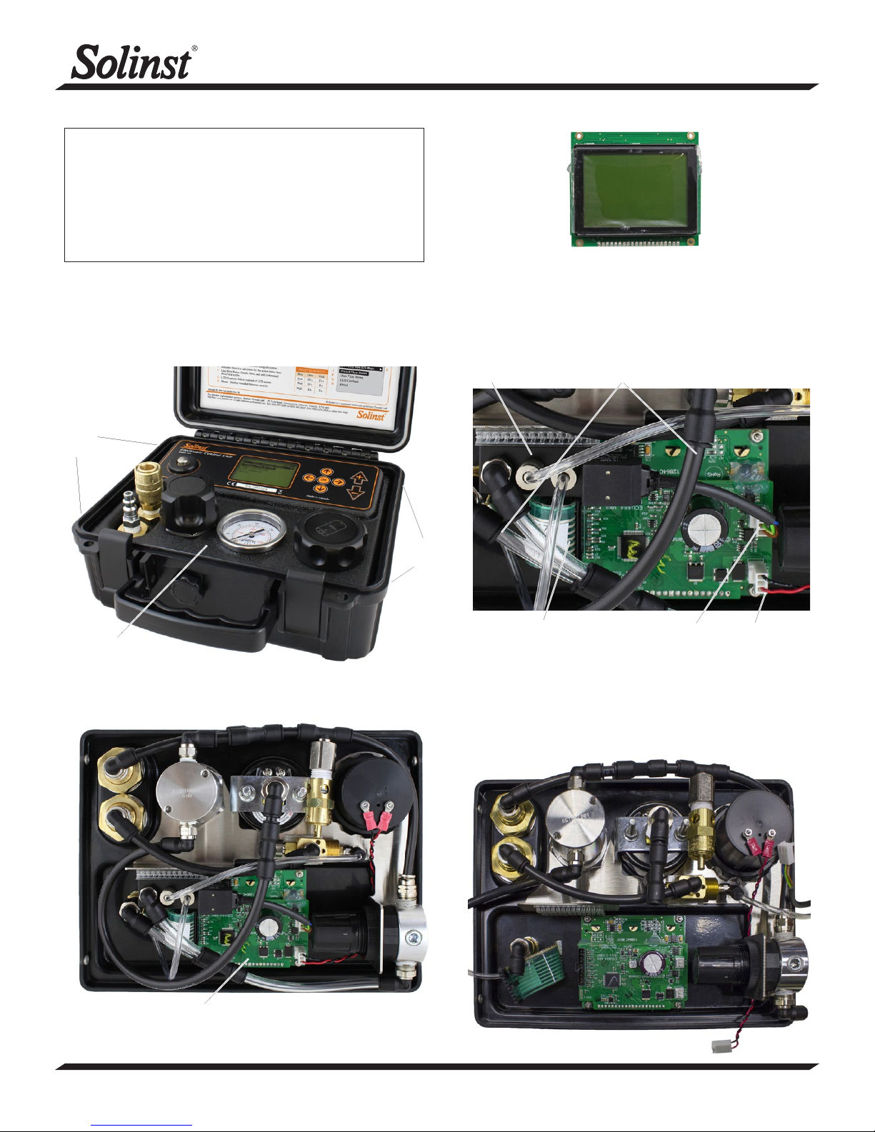
Hex
Screws
Model 464 Mk3 250 psi
464 Mk3 250 psi Controller Board Assembly (#113871)
4. To gain better access to the controller board, disconnect any
tubing that may be in the way. To remove the tubing, push on the
“grasping ring” of the black tubing fitting (to release tubing) and pull
the tubing out. Remember where the tubing was connected.
Solenoid Assembly
Disconnect Tubing
Hex
Screws
Panel
3. Remove the panel from the Control Unit and flip it over to access
the controller board assembly.
Label Ribbon Cable
5. Pull to remove the battery connector and solenoid connector from
the circuit board.
6. Disconnect tubing as required from the solenoid assembly. Pull to
remove the solenoid assembly from the panel. Remember how it
was connected.
7. Press the tabs on the label ribbon cable to unlock and pull it from
the circuit board. You may need to use needle nose pliers.
Solenoid Connector
Battery Connector
Controller Board
Assembly
®
Solinst is a registered trademark of Solinst Canada Ltd.
(Page 1 of 2)
High Quality Groundwater and Surface Water Monitoring Instrumentation
Page 2
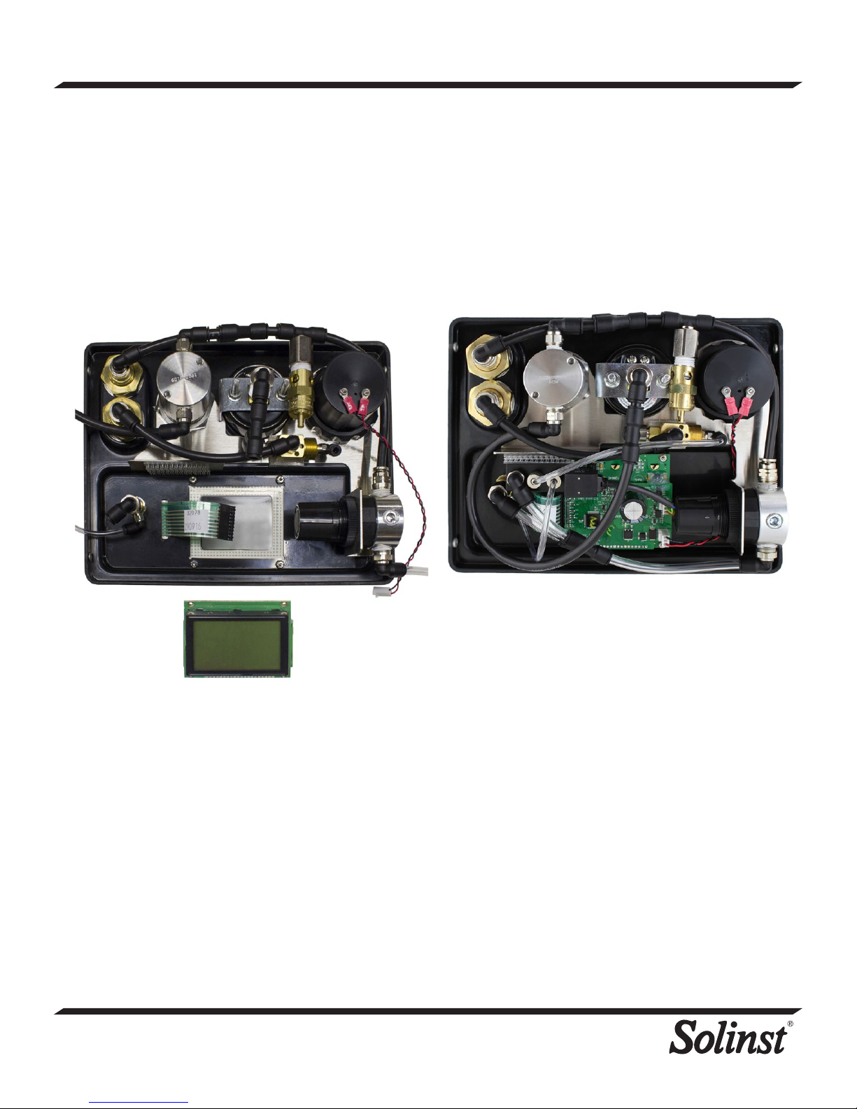
8. Use the 3/16" nut driver to undo the four nuts holding the controller
board assembly in place. Remove any washers. Be careful not to
lose any washers or nuts.
9. Slowly pull to remove the controller board assembly from the back
of the panel. This may take some force as the assembly may be
stuck to the adhesive on the back of the button faceplate label.
10. Leave any washers below the controller board assembly in place on
the mounting screws.
12. Place the new controller board assembly over the four mounting
screws on the back of the panel. Make sure the controller board
assembly is oriented correctly.
13. Put any washers back over the four screws. Use the nut driver
to tighten the for nuts, securing the controller board assembly in
place.
14. Reconnect the label ribbon cable to the circuit board.
11. Peel any protective plastic from the LCD on the new controller
board assembly.
15. Refasten the solenoid assembly to the panel and reconnect any
tubing by pushing into the fittings.
16. Plug the battery and solenoid connectors into the circuit board.
17. Reconnect any other tubing removed by pushing back into the
fittings.
18. Place the panel in the Control Unit case.
19. Reinstall the batteries. Test the Control Unit to ensure proper
connections were made.
20. Reinstall the four hex screws.
Printed in Canada
February 5, 2018
(#113872)
(Page 2 of 2)
35 Todd Road, Georgetown, Ontario Canada L7G 4R8
Web Site: www.solinst.com E-mail: [email protected]
For further information contact: Solinst Canada Ltd.
Fax: +1 (905) 873-1992; (800) 516-9081 Tel: +1 (905) 873-2255; (800) 661-2023
 Loading...