

Page 1
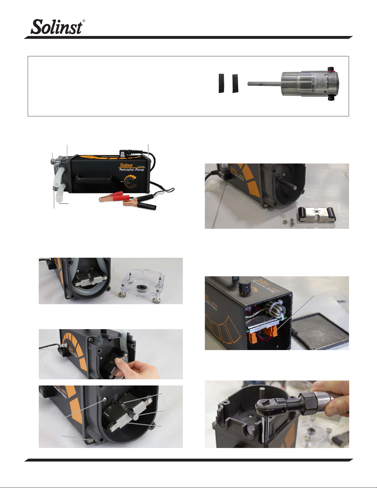
Tools and Materials Needed
1. Replacement Motor Assembly (#114331)
2. 9/64" (3.60 mm) Allen Key
3. 11/32" (8.70 mm) Nut Driver
4. Phillips Screwdriver
5. 5/16" (8 mm) Hex Socket Driver
Instructions
Pump Head
Cover
Thumbscrews
Pump Head
Tubing Inlet
and Outlet
End Plate
Motor Replacement
Model 410 Mk4
Replacement Motor Assembly (#114331)
3. Use the 9/64" (3.60 mm) Allen key and 11/32" (8.70 mm)
nut driver to unscrew and remove the socket screw, nut,
and washer from the head roller. Remove the head roller
from the motor shaft.
Model 410 Mk4 Peristaltic Pump (#112981)
1. Disconnect the pump from the power supply and loosen
the four thumbscrews on the pump head by hand. Remove
the pump head cover.
2. Manually rotate the head roller while pulling gently on the
tubing to pull it from the pump head.
Socket
Screw
4. Use the socket driver to remove the four tapping screws
from the end plate (opposite end from pump head).
5. Carefully slide the control board out of the pump housing.
6. Unplug the 4-pin connector (with red and black wires) from
the control board.
4-pin
Connector
7. Use the socket driver to remove the four tapping screws
from the pump head. Remove the pump head, with motor
connected, from the pump housing.
Phillips
Screw
Tapping
Screw
(Page 1 of 2)
Motor
Shaft
Head
Roller
...continued overleaf
High Quality Groundwater and Surface Water Monitoring Instrumentation
Page 2
Motor Replacement
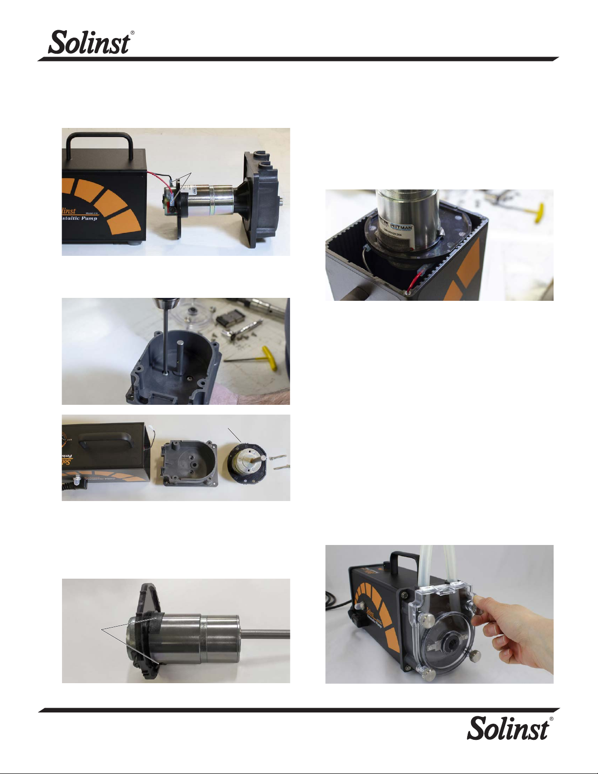
8. Disconnect the black and red wires from the motor
assembly.
Black & Red
Wires
9. Unscrew the Phillips screws from the pump head and
remove it from the motor assembly.
Motor Brace
10. Remove the foam tape and slide the motor brace from the
old motor.
11. Slide the motor brace onto the new motor until it seats
against the two terminals. Secure in place using the two
new pieces of foam tape.
12. Use the Phillips screws to connect the pump head to the
new motor assembly.
13. Attach the black and red wires to the new motor assembly
(black wire to the black negative terminal, and red wire to
the red positive terminal on the motor assembly).
14. Align the tabs on the motor brace with the grooves in the
pump housing and insert the new motor assembly into the
pump housing.
15. Secure the pump head to the pump housing with the four
tapping screws.
16. Plug the 4-pin connector back into the control board.
17. Slide the control board back into the pump housing using
the slots in the sides of the housing.
18. Carefully push all wires into the housing and screw the end
plate back on the pump housing.
19. Rotate the shaft of the motor so the screw hole in the shaft
is vertically facing. Slide the head roller onto the motor
shaft, centre it, and secure it using the screw, washer,
and nut. Make sure the head roller turns freely and is not
touching the pump head.
20. Position the tubing around the impeller in a “U” shape with
equal lengths. Turn the impeller to the 6 and 12 o’clock
position and push the right hand tubing into the tubing
pathway, holding near the bottom. Rotate the impeller
clockwise until tubing is in place. Push the left half of the
tubing into place and rotate the impeller.
21. Position the pump head cover and screw it firmly in place
by hand. Thumbscrews should be finger tight. Do not use a
wrench or over-tighten.
Foam
Tape
Printed in Canada
April 11, 2019
(#114332)
(Page 2 of 2)
For further information contact: Solinst Canada Ltd.
Fax: +1 (905) 873-1992; (800) 516-9081 Tel: +1 (905) 873-2255; (800) 661-2023
35 Todd Road, Georgetown, Ontario Canada L7G 4R8
Web Site: www.solinst.com E-mail: [email protected]
®
Solinst is a registered trademark of Solinst Canada Ltd.
 Loading...