

Page 1
Peristaltic Pump Operating Instructions
IMPORTANT
• Pump is water resistant but not waterproof. Do not submerge in water.
• Pumping rates will decrease with elevation, and as the amount of
lift increases.
• Remove tubing when stored.
• Replace the tubing regularly. The pump will be inefficient if the
tubing is worn. This will show as a limited ability to lift water. If the
tubing looks worn, flattened or cracked, replace the tubing.
• If used in cold weather, ensure that there is no ice in the tubing
before starting the pump.
• Pump is not designed for long-term continuous uninterrupted use.
• To avoid motor damage due to over-heating, allow pump to cool fully
at least every 7 - 8 hours, or more often under high ambient heat
conditions.
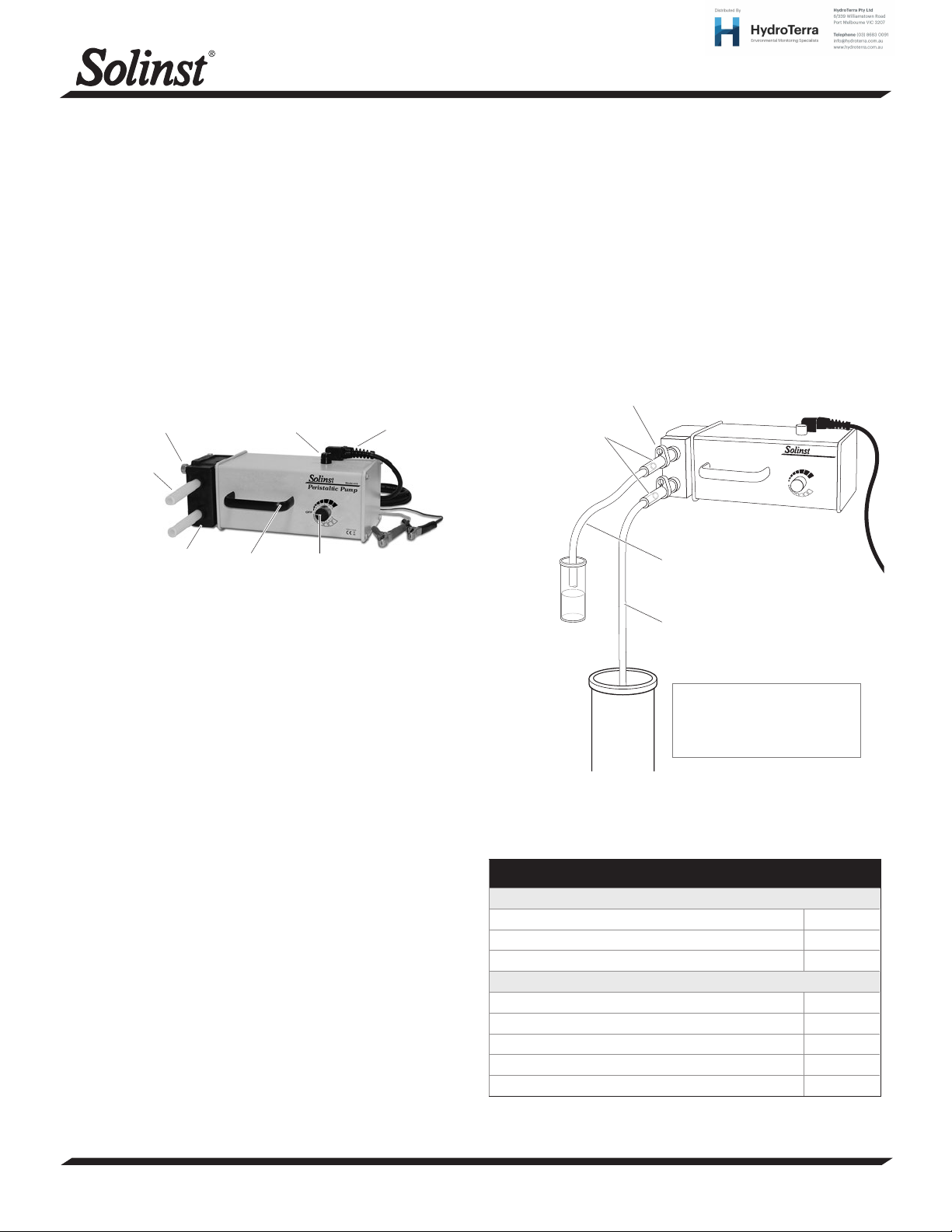
Thumbscrews
5/8" Silicone
Tubing
Fuse
Power Cable
Model 410
1. Ensure that the chosen silicone tubing has been properly installed
in the pump head, with clamps close to the Drive Head.
2. Connect one end of the silicone tubing to the down-hole sample
line. See diagram below.
3. Either connect the other end of the silicone tubing to a discharge
tube, or simply discharge out of this end of the tubing. See diagram
below.
4. Connect the negative (black) battery clip to the negative terminal
post on a 12V DC battery and the positive (red) battery clip to the
positive terminal.
5. Turn the dial in the direction required and adjust the flow as desired.
Tube Clamps
Drive Head Tubing
(5/8" or 3/8")
Peristaltic Pump
Model 410
Drive Head
Handle
Dial
Model 410 Peristaltic Pump (#108592)
Power
The pump operates from an external 12V DC power supply such as a
car, truck or marine 12 volt battery and has a 12 ft (3.6 m) power cable
with connector clips for direct battery connection.
The power cable clips are oversized for use with automotive batteries.
The red clip connects to the positive (+) battery terminal, black to negative (-) battery terminal. If the battery is connected with reverse polarity
the pump will not be harmed, but it will NOT operate until the polarity
is connected correctly.
An externally accessible fuse holder is located on the side of the pump
case. In the event of a blown fuse due to a stalled pump head, replace
fuse with an 8 AMP, type 3AG (1/4" x 1 1/4") ‘Slo-Blow’ fuse.
Do not use a larger amperage fuse.
If the pump is to be powered by a vehicle battery for more than 3
continuous hours, start vehicle and run for 15 minutes to recharge the
battery.
Operation
• The Solinst Peristaltic Pump has an integral Forward/Reverse,
variable flow dial with an OFF position, which has a central detent.
When turning the unit OFF, ensure you feel the dial snap into
position.
• The pump should always be kept with the control in the OFF
position when it is being attached to a power source or stored.
• Once attached to a power source, turn the dial in the direction
required and adjust the flow as desired.
• The standard 5/8" (16 mm) OD medical grade silicone tubing can
be attached to 1/2" (13 mm) OD down-hole sample tubing and
gives purge rates up to 3.5 L/min and 120 mL/min at the low end.
• The optional 3/8" (10 mm) OD silicone tubing and adaptor kit allows
the use of 1/4" (6 mm) OD down-hole sample tubing, giving flow
rates up to 900 mL/min and sampling rates as low as 40 mL/min.
Extra tubing may be connected,
or the sample can just discharge
out of the drive head tubing
Down-hole Tubing
(1/2" or 1/4")
Down-hole tubing is inserted
inside the drive head tubing by
about 1" (25 mm). The friction-
t holds the tubing together.
Model 410 Peristaltic Pump Setup
Down-hole Tubing Specications
Use with Standard 5/8" OD
1/2" OD x 3/8" ID LDPE (100 ft coil) 109490
1/2" OD x 3/8" ID LDPE (250 ft coil) 109489
1/2" OD x 3/8" ID LDPE (500 ft coil) 109488
Use with Optional 3/8” OD (with Adaptor Kit)
1/4" OD x 0.17" ID LDPE Tubing (100 ft coil) 109465
1/4" OD x 0.17" ID LDPE Tubing (250 ft coil) 109464
1/4" OD x 0.17" ID LDPE Tubing (500 ft coil) 109463
1/4" OD x 0.17" ID Teon-lined LDPE Tubing (100 ft coil) 109454
1/4" OD x 0.17" ID Teon-lined LDPE Tubing (250 ft coil) 109444
Continued overleaf...
®
Solinst is a registered trademark of Solinst Canada Ltd.
(Page 1 of 2)
High Quality Groundwater and Surface Water Monitoring Instrumentation
Page 2
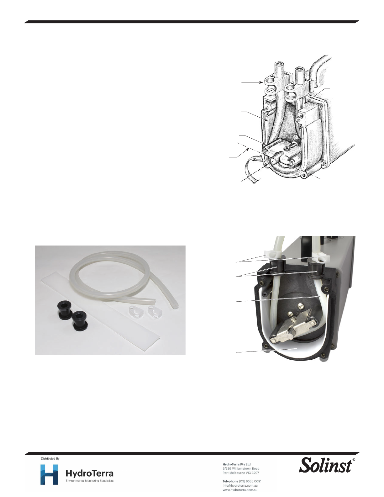
Changing or Installing 5/8" Silicone Tubing
1. To install or replace the tubing, disconnect the pump from its
power supply, then undo the four thumbscrews on the drive head
(black plastic end). Remove the drive head cover.
2. Remove tube clamps from the old tubing.
3. Manually rotate the pump impeller in any direction while gently
pulling on the tubing to pull it out of the drive head.
4. Position the new tubing around the impeller in a “U” shape with
equal lengths. Turn the impeller to the 6 and 12 o’clock position
and push the right hand tubing into the tubing pathway, holding
near the bottom. Rotate the impeller clockwise until tubing is in
place. Push the left half of the tubing into place and rotate the
impeller.
5. Replace clamps onto the tubing close to the drive head to prevent
the tubing from being pulled into the drive head.
6. Reposition the pump head cover and screw firmly in place, but
only finger tight. Do not use a wrench or over tighten.
Installing Optional Adapter Kit & 3/8" Tubing (#105055)
Includes:
• 3 ft of 3/8" OD Silicone Tubing
• 2 Tube Clamps
• 2 Tube Bushings
• 1 Drive Head Insert
Position clamps
above tubing
inlet/oulet
Tubing Pathway
Impeller
Rotate until
both sides of the
tubing are pinched
by the impeller
Tubing
Inlet/Oulet
Silicone Tubing
Bushings
Drive Head Insert
Tube Clamps
1. Disconnect the pump from the power supply, then undo the four
thumbscrews on the drive head (black plastic end). Remove the
drive head cover. Remove the existing tubing.
2. Make a “U” shape with the white plastic drive head insert and place
around the tubing pathway in the drive head.
3. Position the new tubing around the impeller, following instruction
#4 at left.
4. Place the bushings onto the tubing making sure they are placed
INTO the drive head tubing inlet/outlet.
Tubing Clamps
Bushings
3/8" OD
Silicone Tubing
Drive Head Insert
Peristaltic Pump with Tubing Adaptor Kit Installed
5. To prevent the tubing from being pulled into the drive heads, place
the clamps onto the tubing, close to the bushings and using the
narrower clamp position.
6. Re-position the pump head cover and screw it firmly in place, but
only finger tight. Do not use a wrench or over tighten.
Printed in Canada
August 22, 2014
(#106995)
(Page 2 of 2)
For further information contact: Solinst Canada Ltd.
Fax: +1 (905) 873-1992; (800) 516-9081 Tel: +1 (905) 873-2255; (800) 661-2023
35 Todd Road, Georgetown, Ontario Canada L7G 4R8
Web Site: www.solinst.com E-mail: [email protected]
®
Teflon is a registered trademark of DuPont Corp.
 Loading...