

Page 1
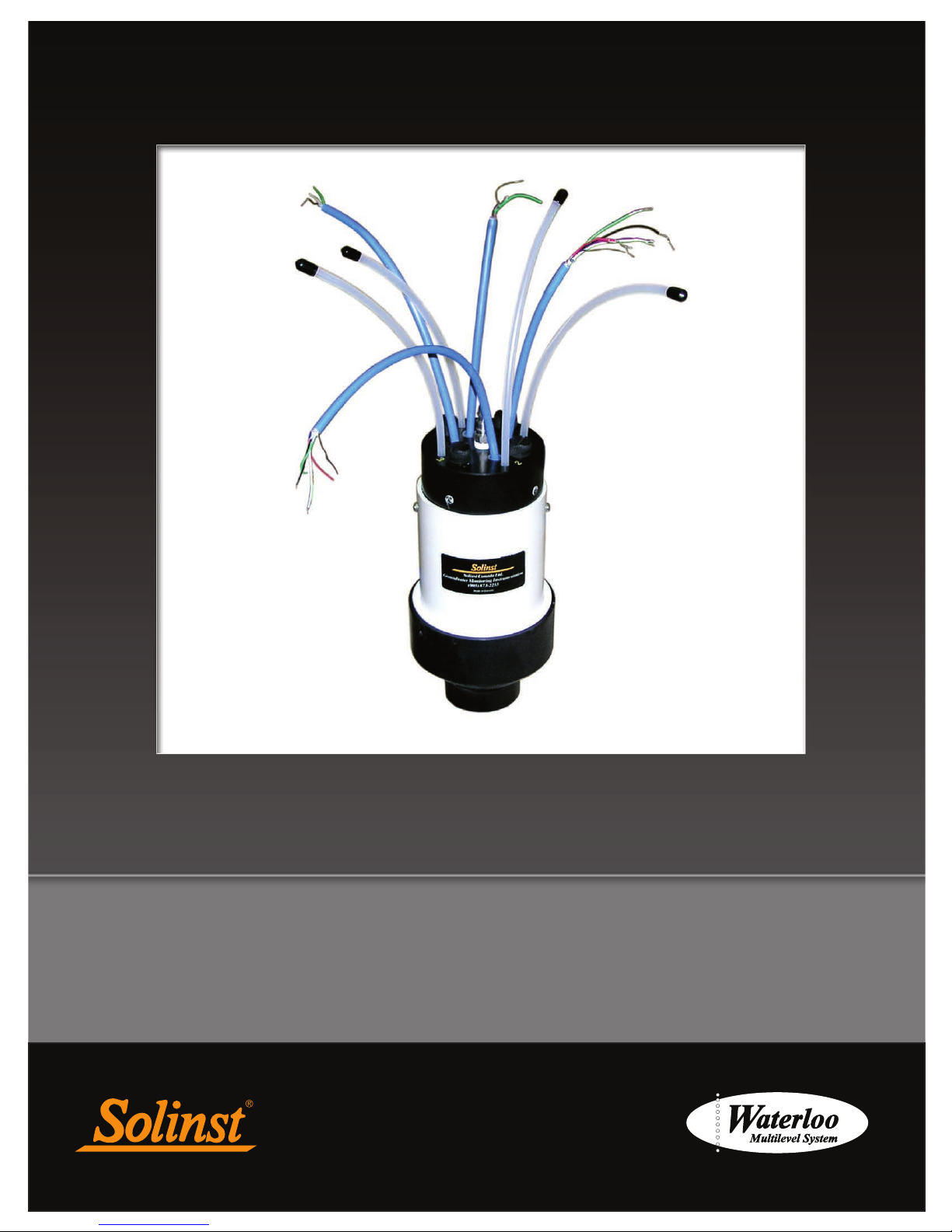
Groundwater Monitoring System
Waterloo Multilevel
Assembly Manual
April 2, 2018
Page 2

Page 3

Waterloo Multilevel System Assembly Manual
Table of Contents
Waterloo Multilevel System Pre-installation Requirements 1
1.0 Introduction 2
2.0 Installation Components 3
3.0 Preparation 4
4.0 Assembling the System 5
5.0 Joint Connections 8
6.0 Port Connections 10
6.1 Attaching Open Tubes 10
6.2 Attaching Vibrating Wire Transducers (VWT) 11
6.3 Attaching a Pump (Bladder or Double Valve) 14
7.0 Testing Monitoring Equipment 16
8.0 Packer Activation 17
9.0 Wellhead Manifold Completion 18
9.1 Standard Option 18
9.2 Multipurge Option 19
9.3 Wellhead Protection 20
10.0 Monitoring Options 21
Appendix
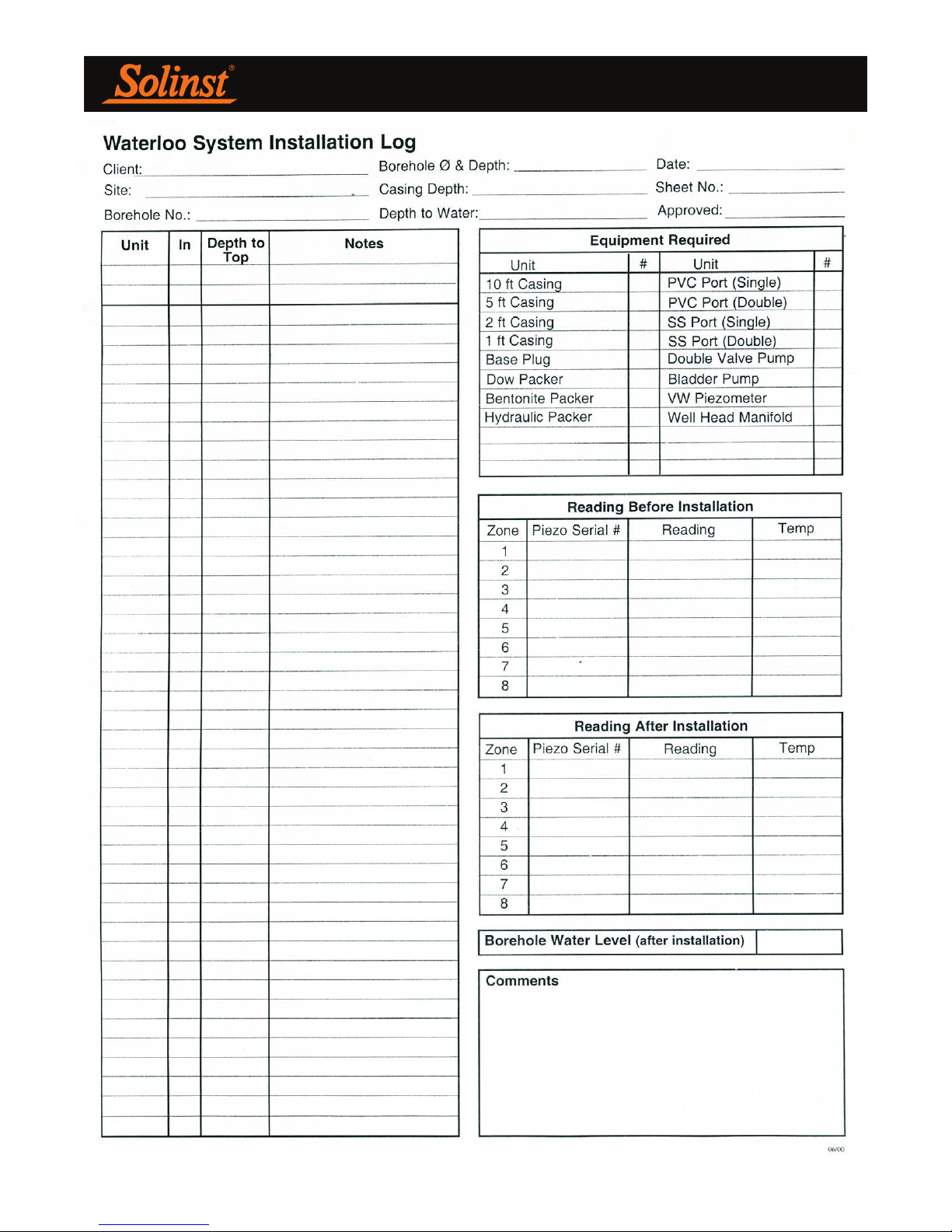
- Waterloo System Installation Field Log I
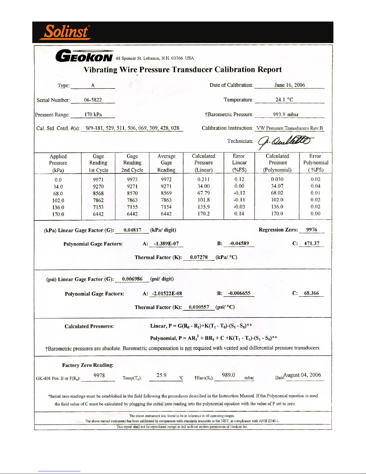
- Vibrating Wire Transducer Calibration Report II
- Sample Vibrating Wire Calculation III
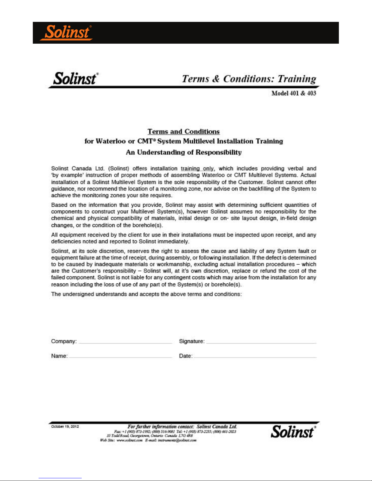
- Training Terms and Conditions IV
Page 4

Page 5

Waterloo Multilevel System Assembly Manual
Waterloo Multilevel System Pre-installation Requirements
Please complete this form to verify that proper consideration has been given to design and borehole specifications for
each Waterloo Multilevel System to be installed.
1/ Minimum information required for effective design of the Waterloo Multilevel System:
Accurate borehole depth ________________ Borehole angle _____________________
Depth to which Waterloo System is to be installed _______________________
Borehole geology __________________ Drilling method ______________________
Casing size (minimum ID) _________________ Depth to base of well casing ______________________
*Borehole diameter (max and min) ________________________
Approximate depth to static water level _____________________
Expected pressure heads at each monitoring zone _____________________
Number of monitoring zones ________________________
Desired port and packer locations/depths _______________________
Site conditions (e.g. dry field, bush, swamp, paved, etc.) ___________________________________________
Any special surface requirements for completion __________________________________________________
of installation (e.g. flush mounted, angled, etc)
Monitoring equipment required ________________________________________________________________
(double valve pumps, bladder pumps, vibrating wire transducers, water level meters for open tubes, etc.)
*Note: Boreholes must be stable, circular, smooth and straight for best packer seal.
Using the layout of monitoring equipment at the proposed depth, Solinst can assist the client in
determining the appropriate number of components to achieve your proposed monitoring scenario for
the Waterloo Multilevel System. Final design and installation details remain the responsibility of the
purchaser. Call for details about installation training.
2/ Ensure that these additional items are available on site during installation:
• Suitable and safe working area
• Clean water (~20 US gal (75 L)/100 ft. (30 m) installation)
• Compressed air or nitrogen to test pumps if installed
• Proper regulator for compressed air or nitrogen cylinder
• Pump Controller for testing pumps
• Readout unit to read Vibrating Wire Transducers
• Water Level Meter to check levels during installation
• Device to check total depth of borehole
• At least two client representatives for the installation
• Support device to assist in lowering Systems where depth to water is deeper than 100 ft. (30 m)
Page 1
Page 6

Waterloo Multilevel System Assembly Manual
1.0 Introduction
The Waterloo Multilevel Monitoring System is comprised of modular units
designed to allow discrete monitoring from several zones within a single
borehole. A variety of portable and dedicated instrumentation allows users to
retrieve samples, determine piezometric head, temperatures, and conduct basic
hydraulic conductivity tests at each zone.
The System uses modular components of various casing lengths, which form
a sealed casing string. Sampling Ports are usually isolated using Packers, or
alternating layers of sand and seal for direct burial option. All instrument tubing
and cabling is contained within these modules and collected at the top of the
system into an efficient and simple Wellhead Manifold.
This manual describes the above-ground assembly of the Waterloo System,
including: preparation, joint connections, port connections, testing monitoring
equipment, packer activation, and manifold completion.
For best results, please review this entire manual before proceeding with your
installations.
Page 7
Waterloo Multilevel System Assembly Manual
2.0 Installation Components
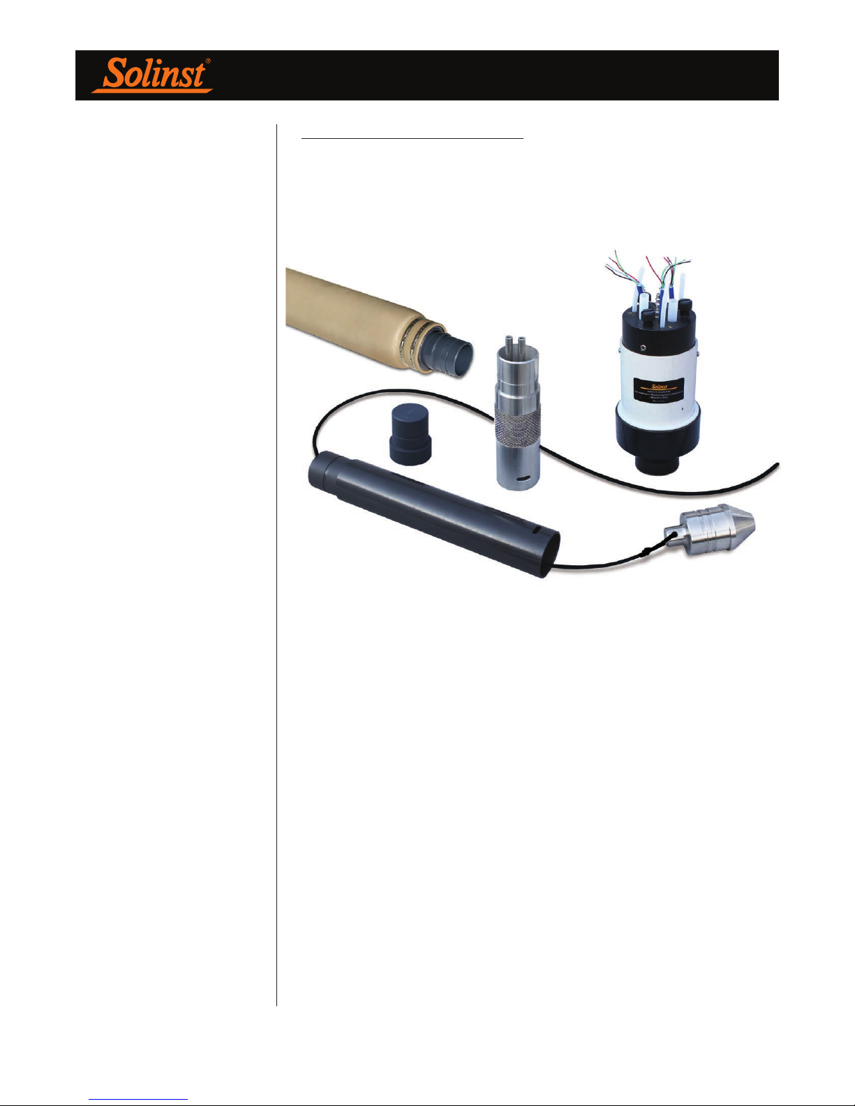
Individual components of the Waterloo Multilevel System include: PVC Casing,
stainless steel Base Plug or PVC Base Plug, stainless steel Ports (single and dual
stem), Permanent Packers, and Wellhead Manifolds. Components are shown in
Figure 2-1.
Figure 2-1 Installation Components
Page 8
Waterloo Multilevel System Assembly Manual
NOTE
In designing the layout, it is
preferable to allow one to two feet
of clearance above the bottom
of the borehole. Problems of
measurement inaccuracy, sloughing
during installation, and other
unforeseen events which may
prevent well completion are thus
minimized.
NOTE
If the depth to water is greater than
100 ft. (30 m) below ground surface,
lower the system with the support
cable and drilling rig.
3.0 Preparation
The number and specific order in which each component of the System are to
be assembled must be determined ahead of time. The depths of the desired
monitoring zones and layers of backfill (where applicable) must be determined in
advance of the installation. The design log will serve as a reference during the
install. Ensure that an ‘as built’ installation log is maintained. See Appendix I for
an example of a “Waterloo System Installation Log”.
Before the install date, reconfirm that the borehole is still open to its target
depth. Once the Waterloo System is received, make sure that the shipment
looks complete and that nothing appears damaged. Contact Solinst immediately
to resolve any issues before proceeding with the install.
If a Solinst Trainer is requested, the training will be completed in its entirety,
prior to starting the installation. See Appendix IV for the Terms and Conditions
of training.
The System weighs about 1 lbs/ft., which doesn’t include the weight of the
Packers. Therefore, at least two physically strong field assistants will be needed
to lower the System by hand. If the depth to water is more than 100 ft. (30 m)
below ground surface, then a hoisting winch (drilling rig) will be needed to assist
with holding and lowering the System via an optional support cable.
Tools and equipment you should bring for the installation:
NOTE
Be sure to document the position
and placement of each downhole
component, during the installation.
An ‘as built’ installation log is a
crucial part of knowing where each
monitoring zone is placed.
• Appropriate safety precautions and equipment to ensure a safe
working environment at your site
• Water Level Meter/Well Depth Indicator
• Lights and/or security if the installation goes beyond daylight hours or
more than 1 day is needed to complete the installation
• Plastic sheeting to keep the Waterloo casing, tubing, etc. clean when
being laid out on the ground during installation
• Pylons or traffic cones for safety and to identify the lay down area or
work zone
• Hand-spray water bottle used to lubricate pipe joints
• Two 5 gal pails
• One roll of black electrical tape to temporarily identify the ports and
associated pump tube discharge ends
• 11/16" (18 mm) and 5/8" (16 mm) wrenches
• Hacksaw - to achieve desired System stick-up
• Large dowel or spindle
• Small piece of sand paper to assist in pushing tubing over the pump
stems
Page 4
Page 9
Waterloo Multilevel System Assembly Manual
NOTE
A System about 100 ft. (30 m) below
water will most likely require water
added to the casing string during
installation in order to counter
System buoyancy (see Section 8.0).
When packers are used, the water
inside the casing string should not
exceed the static water level of the
borehole during installation.
4.0 Assembling the System
One person should be assigned as ‘Team Leader’ for the installation. This Team
Leader is key in directing and ensuring that the components of the System are
installed in the correct sequence. The Team Leader will keep an ‘as built’ record
of the Multilevel System.
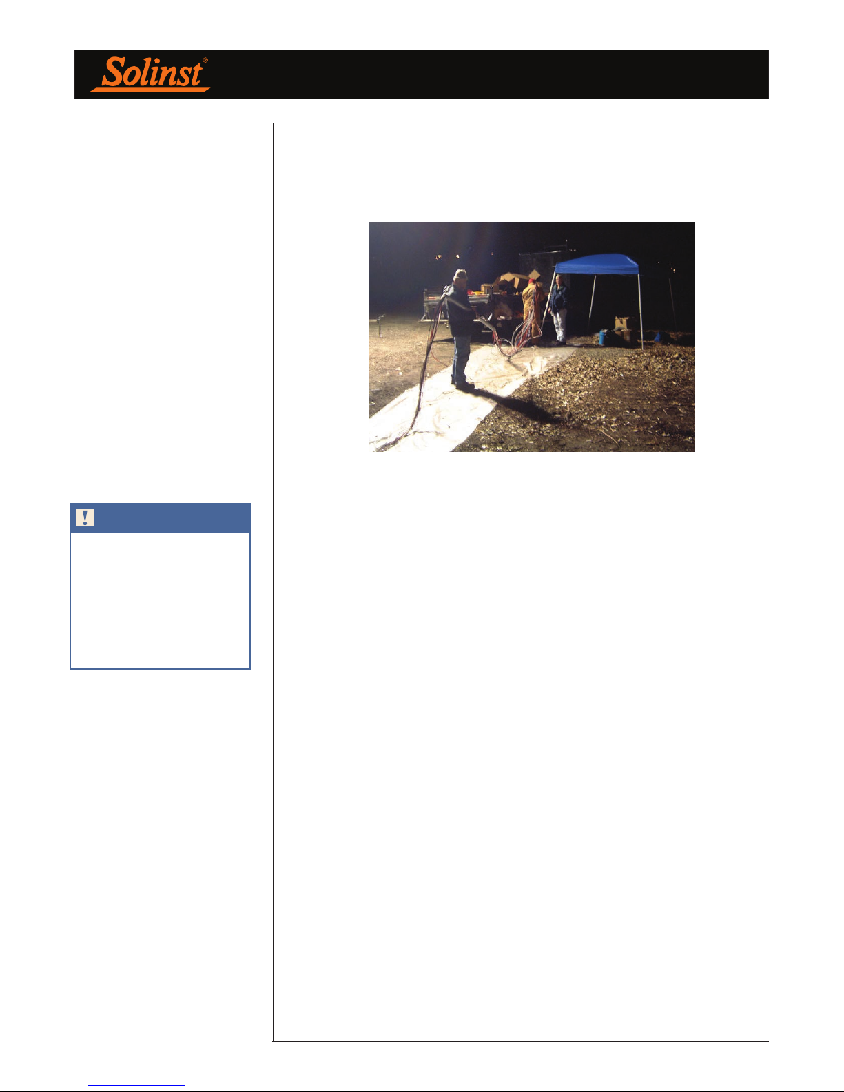
Arrange and group all of the equipment for each separate System near the
borehole. Inventory and record each piece, as is proposed for the System on the
Waterloo System Installation Field Log (see Appendix I for example).
Unpack the (optional) vibrating wire transducers (VWT) and soak them in water.
Preferably submerse them in the borehole or in a bucket of water close in
temperature to borehole groundwater. These need to stabilize prior to obtaining
their individual ‘zero value’ (head/pressure) reading (see Section 6.2).
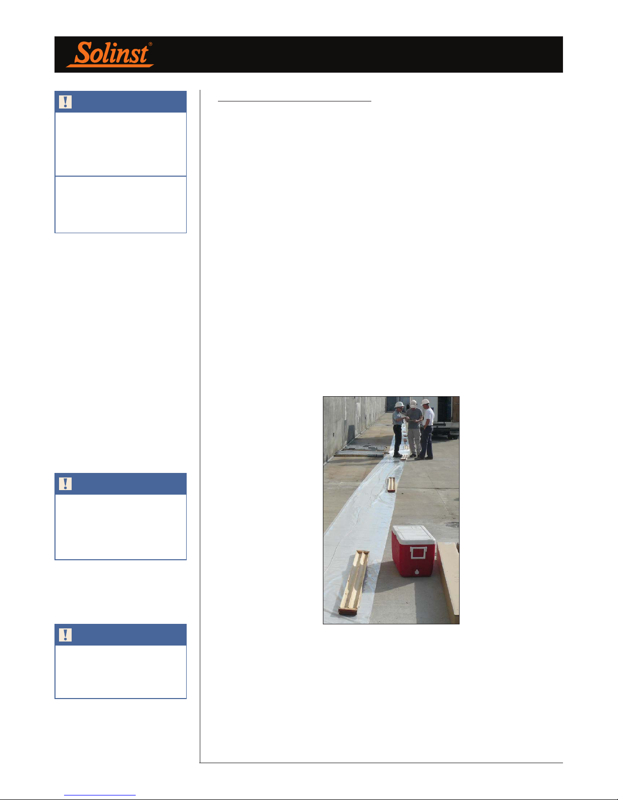
On the most suitable ground surface, measure off and mark a line out from the
borehole 10% longer then the depth to the deepest Port. By example, if the
deepest Port is at 100 ft. (30 m), measure off and make a reference mark at 110
ft. (~33 m). This is your initial reference for cutting tubing. If required, unroll a
~3 ft. (1 m) wide length of thin mil plastic (Visqueen) polysheeting to this mark.
If used, uncoil and lay out the support cable. The outstretched cable will likely be
about 5 ft. (1.5 m) beyond the length of your plastic and reference mark.
NOTE
If not using a support cable,
begin with the Base Plug near
the borehole, and simply follow
the design log to attach the
components in sequence.
NOTE
See Section 5.0 for joint connection
instructions and Section 6.0 for
connecting tubing and/or cabling
to each Port.
Figure 4-1 Plastic & SS Support Cable Laid Out
(Wood core boxes are used here to weigh down plastic)
To begin, attach the stainless steel Base Plug to the end of the support cable
nearest the borehole. Following the sequence as set in your Installation Log, each
component is walked to the far end of the plastic and threaded over the support
cable, female joint end first, and walked back to the borehole for connection to
the previous component. Section 5.0 discusses how to connect each joint.
Page 5
Page 10
Waterloo Multilevel System Assembly Manual
Lock
Adjustment
Knob
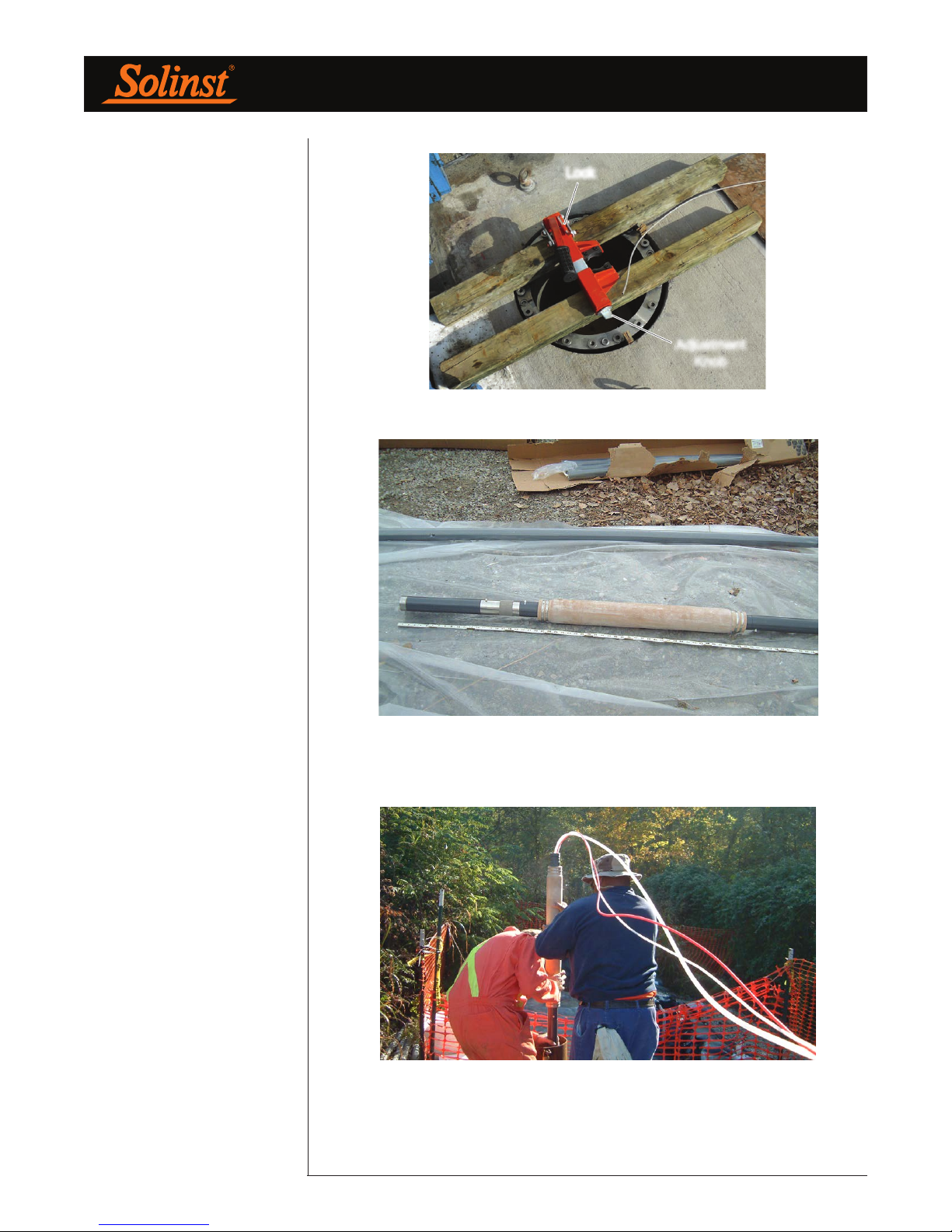
Figure 4-2 An Installation Clamp Over a Borehole
Figure 4-3 A Base Plug, Casing, Port, and Packer Section
Figure 4-4 Initial Section Being Installed Down-hole
Page 6
Page 11
Waterloo Multilevel System Assembly Manual
When adding each Port to the sequence you will connect the monitoring tubing
and/or transducer or pump to be used at that Port. Each successive component
will be threaded over the support cable, as well as the monitoring tubing and
cabling as it is added. Section 6.0 discusses Port connections.
Figure 4-5 Casing Section Being Threaded Over Monitoring Tubing
NOTE
To use the installation clamp, slide
the unlocking bar to the unlocked
position and open the clamp by
lifting the handle. Adjust the width
of the jaws via the adjustment knob
so the casing is held tightly when
the clamp is closed. Return the
locking bar to the locked position.
Once at least 5 ft. (1.5 m) of the System has been assembled, start lowering
the System into the borehole. Adjust and lock the installation clamp onto this
assembly to hold it in place. The System is now hanging in the borehole and
supported by the installation clamp.
Continue to install the System in the sequence shown in your Log, making
each connection as described in the following section. Be sure to record the
components as they are assembled over the borehole on the Installation Log
(see Appendix I).
Page 7
Page 12
Waterloo Multilevel System Assembly Manual
5.0 Joint Connections
Connecting Casing, Packers, & Ports
Figure 5-1 Packer and Casing Joint with Shear Tie
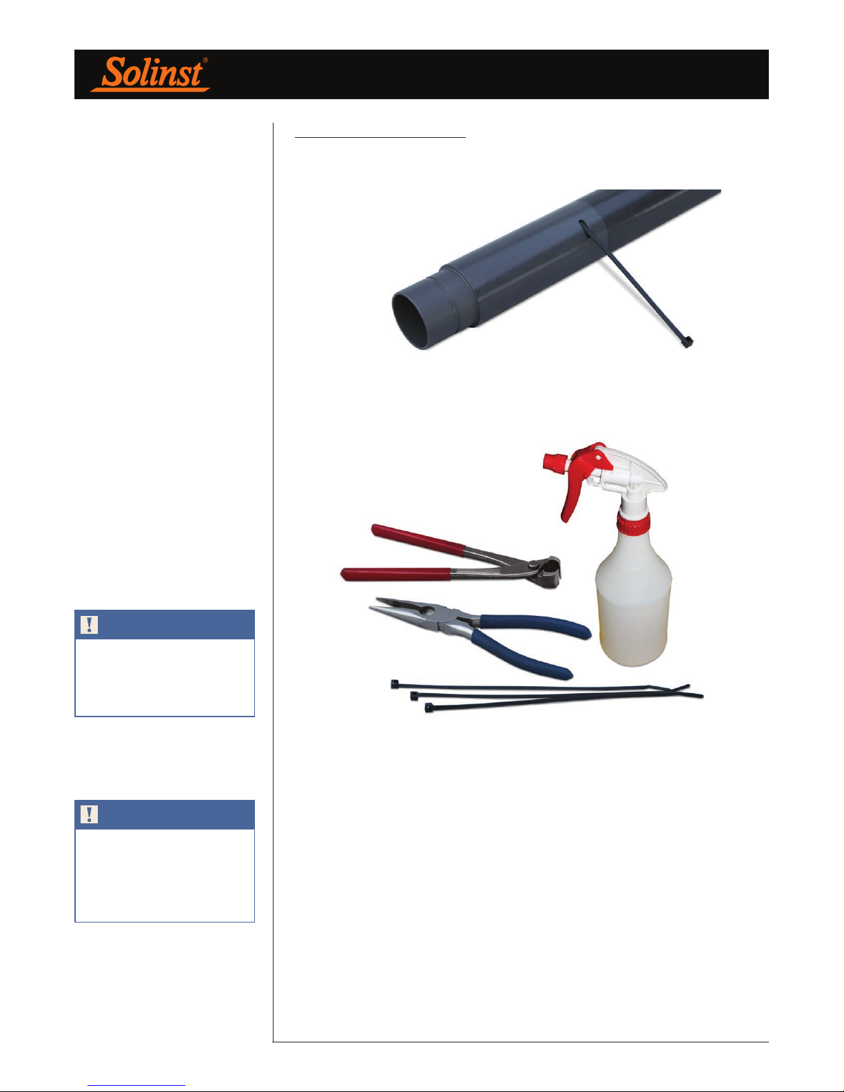
Tools and accessories required: needle nose pliers, Oetiker pliers, hand spray
water bottle, shear ties.
NOTE
Before threading component
sections over the cables/tubing,
feel inside the female joint end to
ensure an o-ring is present.
NOTE
DO NOT place the installation clamp
on the Packers. Simply connect the
next length of casing above the
Packer. This next casing will be the
hold point for the assembly.
Figure 5-2 Tools and Accessories Required
All joints are pushed / twisted together over the borehole while components are
held in-place by the installation clamp or support cable. The male joint end of
the component faces up and the female joint end faces downhole.
Spray the inside of the female and male ends of the components to be attached.
The water spray serves to lightly lubricate the joint to make for an easier
connection, as well as to reduce the risk of tearing the o-ring. When you are
making this connection, be sure not to kink or pinch the monitoring tubes inside
the Multilevel System.
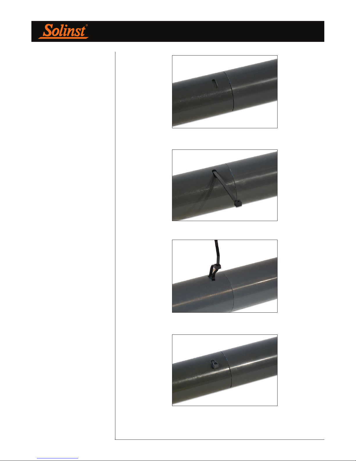
Once the joint is coupled, push the shear tie through the shear window and
around until it exits out the same window. To help with this, needle nose pliers
can be used to grab the tail of the shear tie. Lock and pull the shear tie tight.
Use the Oetiker pliers to snip off the excess ‘tail’.
Page 8
Page 13
Waterloo Multilevel System Assembly Manual
Figure 5-3 Coupled Joint
Figure 5-4 Push Shear Tie Through the Window
Figure 5-5 Pull Shear Tie Tight
Figure 5-6 Cut Off the Excess Shear Tie
Page 9
Page 14
NOTE
1/2”OD x 3/8”ID or 5/8”OD x 1/2”ID
tubing can be used. The 1/2”OD
tubing is clamped directly onto
the Port Stem with an Oetiker #14
clamp, while the 5/8”OD tubing fits
over a 3” length of 1/2”OD tubing
before being clamped to the Port
Stem with an Oetiker #17 clamp.
Waterloo Multilevel System Assembly Manual
6.0 Port Connections
6.1 Attaching Open Tubes
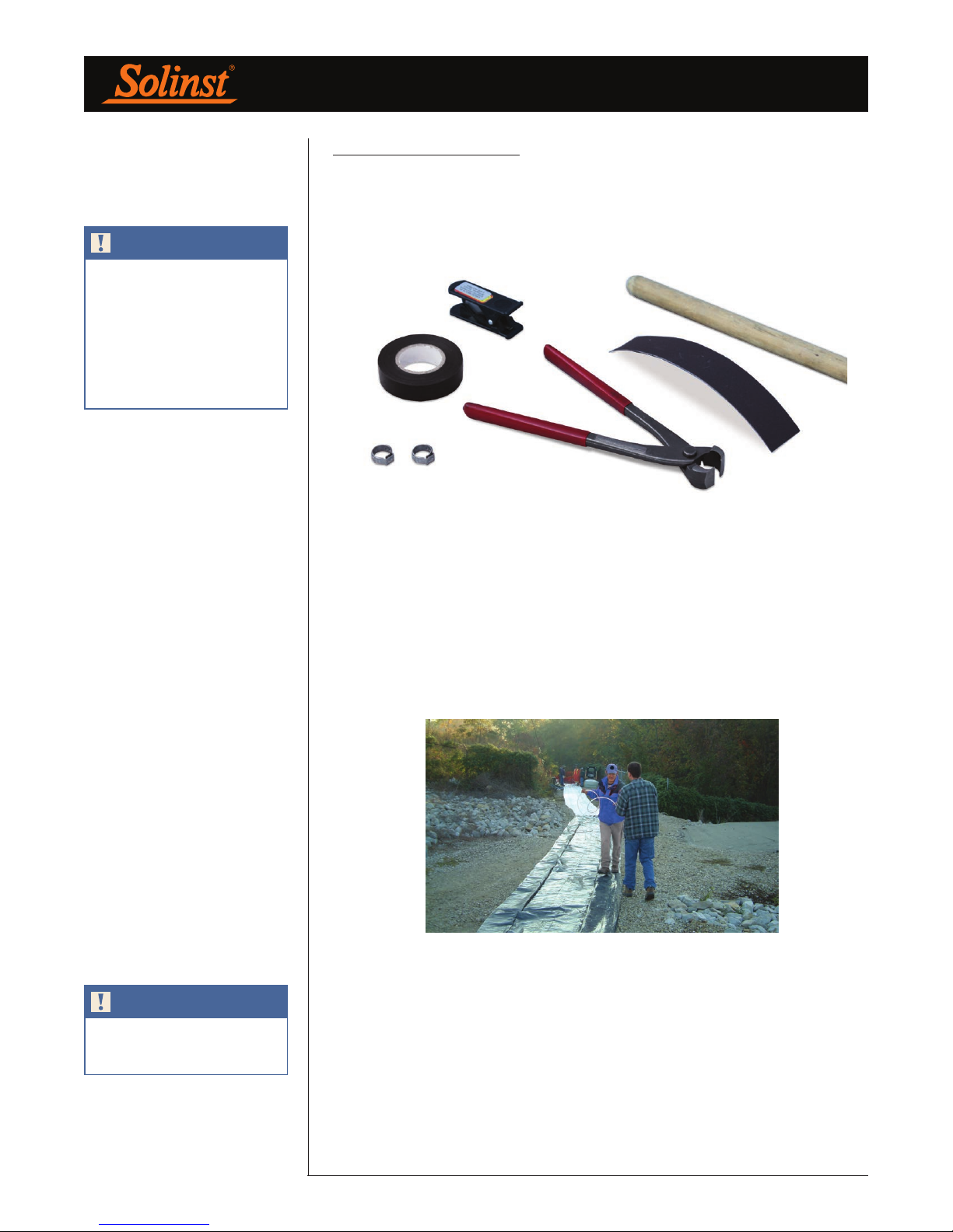
Tools and accessories required: Oetiker pliers, tubing cutter, black electrical
tape, rod/broom handle, sand paper.
Figure 6-1 Tools and Accessories Required
NOTE
Remember to label each tubing/
cable end.
Beginning with the deepest Port (Port 1), stand at the borehole holding the spool
of tubing (1/2"OD x 3/8"ID or 5/8"OD x 1/2"ID). A broom handle or equivalent
pole works well to hold the spool. A second person will ‘walk’ the end of the
tubing to the measured reference mark (Section 4.0). Once the tubing end is
pulled to this reference mark, label the tube about 1 ft. (30 cm) from the tubing
end. Black electrical tape works well. Use the black tape to wrap the number of
bands corresponding to the Port number around the tubing end (i.e. 1 band of
black tape represents Port 1). Cut the tubing at the spool.
Figure 6-2 Tubing Being Pulled to Reference Mark
At the next Port, roll off the tubing to the end of the previous cut tubing length,
and cut at this new reference mark. Use this reference for the remaining Ports,
so as more Ports are added the tubing and cable ends will meet at the same
point. Remember to label each length of tubing as you progress.
Page 10
Page 15
Waterloo Multilevel System Assembly Manual
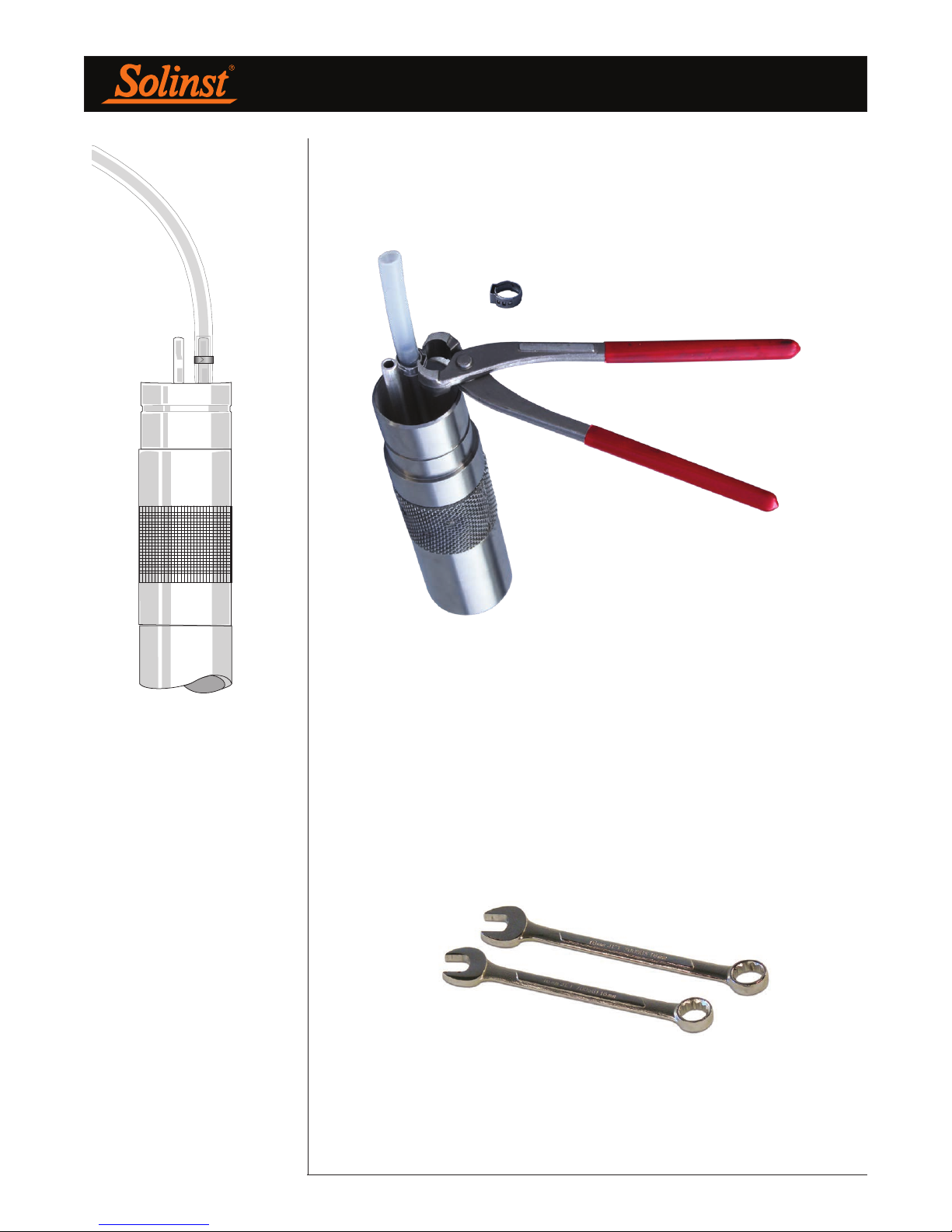
Be sure there is a clean cut to the tubing end at the Port. Place one single ear
Oetiker #14 clamp over the tubing and push the tubing end onto the stainless
steel Port Stem. Using the Oetiker pliers, squeeze the clamp ‘shoulders’ together
to securely attach the tubing to the stem.
5/8"OD x 1/2"ID tubing attached over
Figure 6-3
3" of 1/2"OD x 3/8"ID tubing to Port
Stem Using Oetiker #17 Clamp
Figure 6-4 1/2"OD x 3/8"ID tubing attached to Port Stem Using Oetiker #14 Clamp
Note: if using 5/8"OD tubing, a 3" length of 1/2"OD tubing has to be first pushed
onto the Port Stem. Then the 5/8"OD tubing is pushed over the 1/2"OD tubing
and clamped to the Port Stem with an Oetiker #17 clamp (see Figure 6-3).
6.2 Attaching Vibrating Wire Transducers (VWT)
Tools and accessories required: 11/16" (18 mm) and 5/8" (16 mm)
wrenches.
Figure 6-5 Tools and Accessories Required
Page 11
Page 16
Waterloo Multilevel System Assembly Manual
NOTE
Match the serial number on the
body of the VWT with the label at
the end of the cable.
NOTE
Record the VWT ‘zero value’ on
the Installation Log. It is needed
to benchmark against all future
readings.
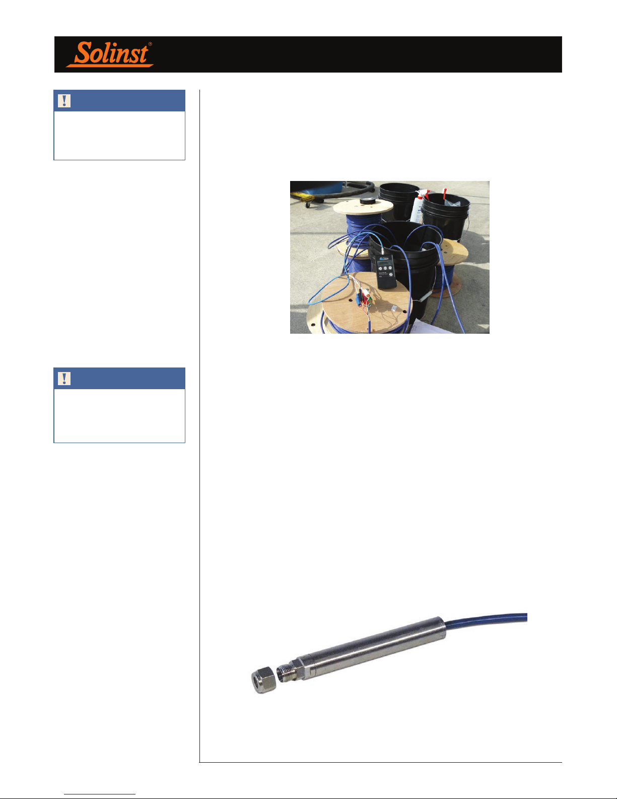
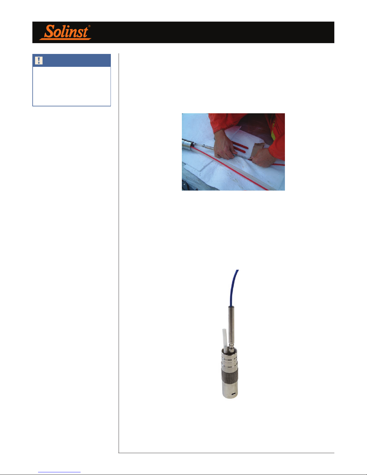
Each one of the VWT’s cables has been cut to the length requested in the original
order. This length also includes an additional 10% contingency. The total cable
length is labeled on the cable’s end.
Match the serial number on the VWT body with the labeled cable end, and its
corresponding “Vibrating Wire Transducer Calibration Report” provided in the
shipment (see Appendix II).
Figure 6-6 Presoaking the Vibrating Wire Transducers
Soak all of the VWTs for about 30 minutes, in either the borehole, or in a bucket
of water at the same temperature as the borehole water. Once the VWT has
stabilized, lift the VWT just out of the water and record the measured transducer
temperature and vibration reading. Record this value on the Installation Log as
the VWT’s ‘zero value’.
Compare this ‘zero value’ to the ‘Factory Zero Reading’ on the Calibration
Report. These values should not differ by more than 0.1% of full scale. Remember
that pressure varies with elevation (your site vs. factory calibration location),
temperature, and barometric pressure.
The ‘zero value’ is used to subtract from all future pressure/head readings to
calculate final depth to water measurements. See Appendix III for a sample
depth to water calculation.
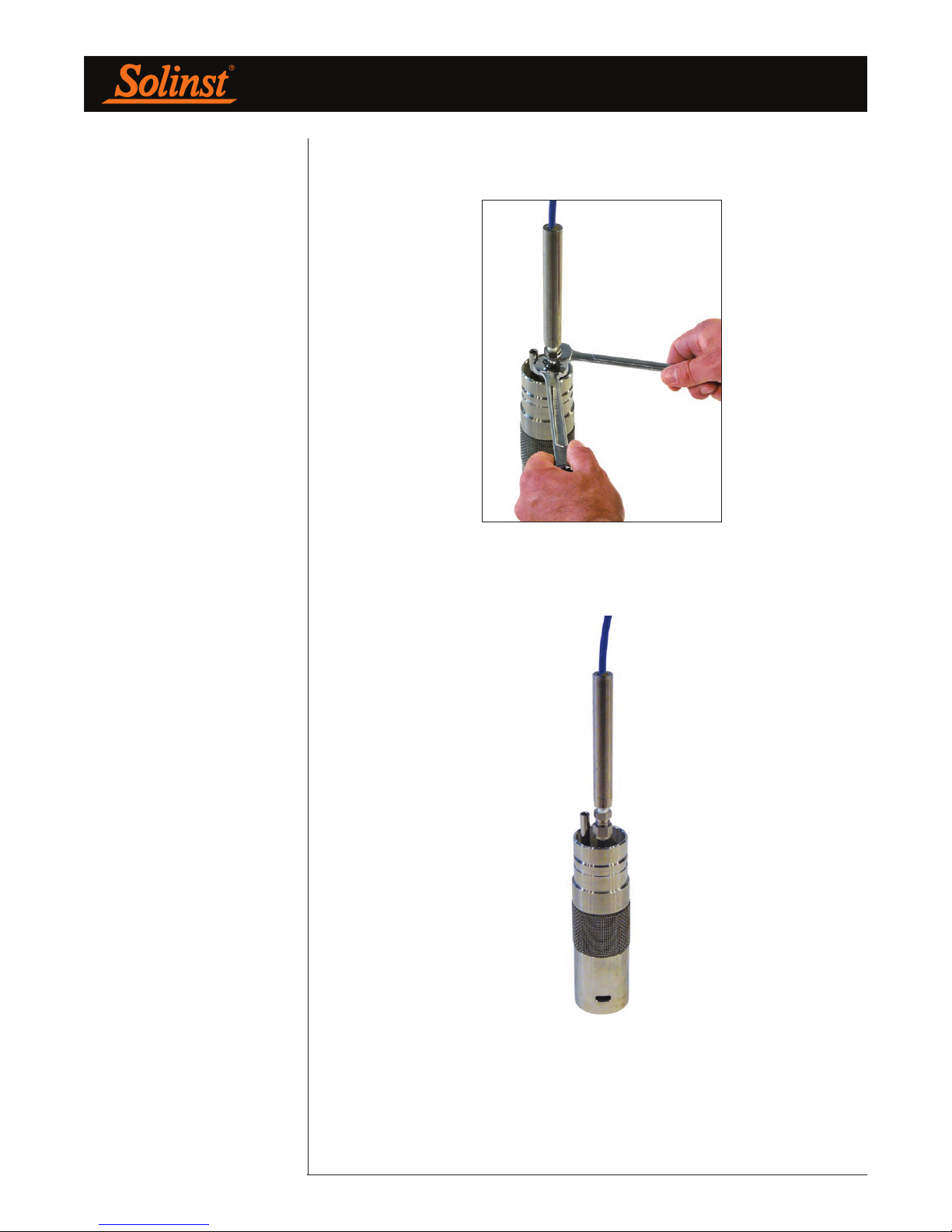
Uncoil the VWT’s cable out to its full length. Push the 3/8" SS compression
fitting with attached VWT onto the Port Stem. Using the 11/16" and 5/8"
wrenches, tighten the two compression fitting nuts onto the Port Stem by 1 and
1/4 turns.
Figure 6-7 Vibrating Wire Transducer
Page 12
Page 17
Waterloo Multilevel System Assembly Manual
Figure 6-8
Figure 6-9
Page 13
Page 18
Waterloo Multilevel System Assembly Manual
6.3 Attaching a Pump (Bladder or Double Valve)
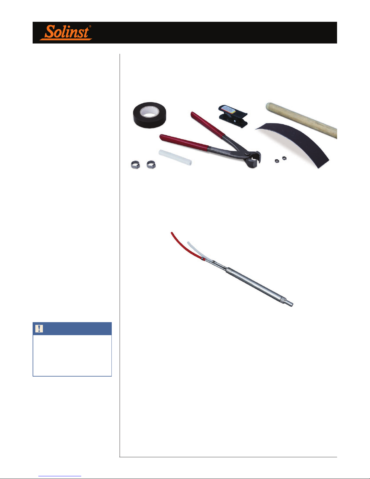
Tools and accessories required: tubing cutter, Oetiker pliers, Oetiker clamps,
sand paper, 4" (10 cm) of 1/2"OD x 3/8"ID tubing, black electrical tape,
rod/broom handle.
Figure 6-11 Tools and Accessories Required
Figure 6-10 Tools and Accessories Required
There are two stems on each pump. The shorter stem is the sample stem, which
the sample line (white/natural) will be connected to. The longer stem is the drive
gas stem, which the drive line will be connected to. Depending on whether you
use LDPE or PTFE-lined, the drive line may be red colored or white/natural,
respectively.
NOTE
Use the black tape to wrap the
number of bands corresponding
to the Port number around the
tubing end (i.e. 1 band of black tape
represents Port 1).
Figure 6-11 5/8"x6" Double Valve Pump
Beginning with the deepest Port (Port 1), stand at the borehole holding the spool
of tubing. A broom handle or equivalent pole works well to hold the spool.
Identify/label the end of this tubing by wrapping a 1" (25 mm) piece of black
electrical tape around the tubing to form a ‘black band’. Let each band represent
the Port number. Here, one band of the tape on the tubing end will represent
that this tubing will be connected to Port 1. If using PTFE tubing, use a different
colour tape to represent the drive line tubing.
A second person will ‘walk’ the end of the labelled tubing to the measured
reference mark. Once the tubing end is pulled to this reference mark. Cut the
tubing at the spool.
At the next Port, roll off the tubing to the end of the previous cut tubing length,
and cut at this reference mark. Use this reference for the remaining Ports, so
as more Ports are added, the tubing and cable ends will meet at the same point.
Remember to label each length of tubing as you progress.
Page 14
Page 19
Waterloo Multilevel System Assembly Manual
NOTE
If you are using PTFE-lined tubing,
be careful not to allow the PTFE
lining to become separated and
cause a visible ‘bubble’ at the Port
Stem.
Make a clean fresh cut to both tubing ends at the borehole. Place one small
double ear Oetiker clamp over each pump stem. Wrap a small piece of sandpaper
around the tubing for ‘traction’ and push the sample tubing over the shorter
pump stem. Use the sandpaper to help push the drive tubing over the longer
pump stem. If you are using PTFE-lined tubing, be sure to check that the PTFE
lining has not become separated from the tubing while pushing it onto the pump
stem. If you see a ‘bubble’ through the tubing, pull it off the stem, make a fresh
cut, and restart this step.
Figure 6-12 Using Sand Paper to Push Tubing onto Pump Stem
Using the Oetiker pliers, incrementally crimp both ears on each clamp. Alternate
from one ear to the other, slowly pinching the ears closed. Repeat this cycle 2 or
3 times to achieve a proper crimp. Once the clamp is closed properly you should
not be able to see light through the ears of the clamp.
Cut a piece of 1/2"OD x 3/8"ID tubing about 4" (100 mm) long. Push this onto
the Port Stem by about 2" (50 mm). Using the Oetiker pliers, crimp a #14
Oetiker clamp over the tubing, attaching it to the Port Stem.
Figure 6-13 Tubing Attached to Port Stem
Page 15
Page 20
Waterloo Multilevel System Assembly Manual
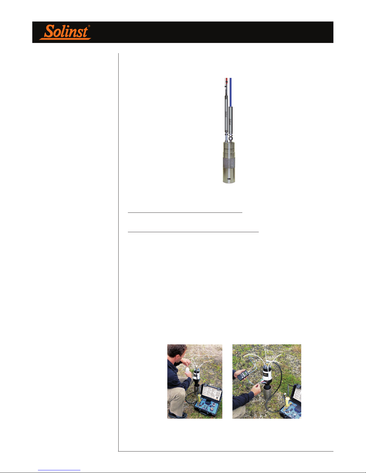
Place another #14 Oetiker clamp over the open 1/2"OD x 3/8"ID tubing end.
Push the pump intake into the tubing end. You will notice that the pump intake
is recessed to receive the Oetiker clamp. Crimp the clamp to the pump.
Figure 6-14 Pump Connected to Port Stem
7.0 Testing Monitoring Equipment
Before Packer Expansion or Backfilling
Tools and accessories required:
For testing pumps: 466 Pump Controller, 466 Drive Line Adaptor to 1/4"OD
tubing (push), drive gas.
For testing Vibrating Wire Transducers: VWT readout unit.
For testing open tubes: Water Level Meter, Peristaltic Pump.
With the Multilevel installed to depth, before adding water to activate the packers
or backfilling the System, (if applicable) individually check and record VWT
readings and pumping discharges to confirm proper connections, installation,
and performance.
Figure 7-1 Testing Pumps and Transducers
Page 16
Page 21
Waterloo Multilevel System Assembly Manual
NOTE
After the addition of water, the
Packers may take 1 - 3 days to
expand. This primarily depends on
the Head differential between the
water in the borehole and the water
in the System. A higher differential
will put more pressure on the
Packers, therefore expanding them
more quickly.
NOTE
Water is used to counter buoyancy
and for ‘sinking’ the System during
installation.
8.0 Packer Activation
Adding Water
Tools and accessories required: water.
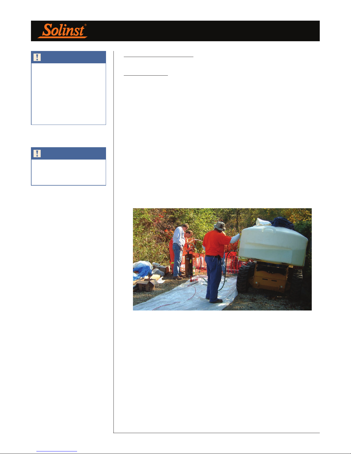
Depending on how many Packers are used, eventually your System will likely
require water to counter buoyancy. As a rule of thumb, when the ratio of the
total length of casing versus the depth to water is greater than 2:1, the System
will float. For example, if the installed length of casing is 50 ft. (15 m) and the
depth to water is 25 ft. (7.5 m), be ready to add water. Add just enough water
to ‘sink’ the System. Do not overfill.
To activate the Packers for expansion you will need about 0.2 USgals/ft.
(2.5 L/m) of clean water (Therefore, a 200 ft. (60 m) Waterloo System requires
about 40 USgals (150 L) of water). Do not overfill the System, and remember
to leave the water level in the PVC Casing below the frost line (if applicable).
Repeated addition of small amounts of water may be required as the Packers
inflate. The water level within the System, versus in the borehole, should not
differ by more than 100 ft. (30 m).
Figure 8-1 Adding Water to the System
Page 17
Page 22
Waterloo Multilevel System Assembly Manual
NOTE
Allow for at least 20” (50 cm) of
clearance above the final PVC
Casing ‘stick-up’ and the underside
of your protective outer enclosure.
This will ensure that you do not
pinch the monitoring tubes and
cables above the completed
manifold.
NOTE
Take a water level reading in the
borehole and record it in the “Water
Level at End” box on the Installation
Log, after the System is installed to
depth.
9.0 Wellhead Manifold Completion
9.1 Standard Option
Tools and accessories required: tubing cutter, Phillips screwdriver, PVC pipe
saw/cutter.
Determine the desired ‘stick-up’ of PVC casing when the system is at its final
depth. If applicable, cut the last piece of PVC Riser to the appropriate length
and install the Riser Clamp to achieve your desired ‘stick-up’. The Riser Clamp
ensures that the proper stick-up is maintained when the System is hung. For
safety, use a casing clamp and lower the System to depth. If you have used the
SS support cable to lower the System, be sure to continue to use this cable to
support the System during the packer expansion (up to three days).
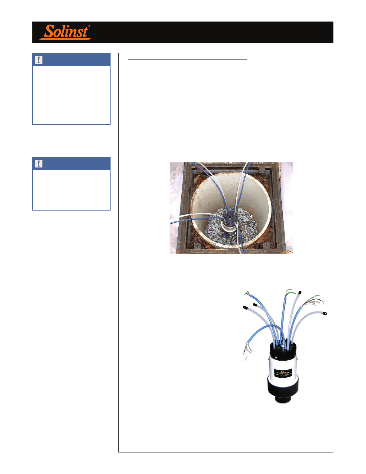
Figure 9-1 Tubing Organized Around the Wellhead
Remove the two Phillips screws from
the white protective housing of the
Wellhead Manifold Base and then
remove the Manifold Base from the 4”
(100 mm) diameter protective housing.
Install this lower (black) portion of
the Manifold (small end first) onto the
completed installed PVC Casing. Using
the numbered Wellhead as a guide,
separate and organize the tubes and/
or cables into a ‘wagon wheel’ pattern
around the Wellhead.
Thread the open tubes, sample tubes
(white) and/or blue VWT cables through
the numbered Wellhead. Re-attach and
screw the numbered Wellhead to the
Manifold Housing at the Wellhead.
Figure 9-2 Tubing and Cables Installed Through a Wellhead
Page 18
Page 23
Waterloo Multilevel System Assembly Manual
9.2 Multipurge Option
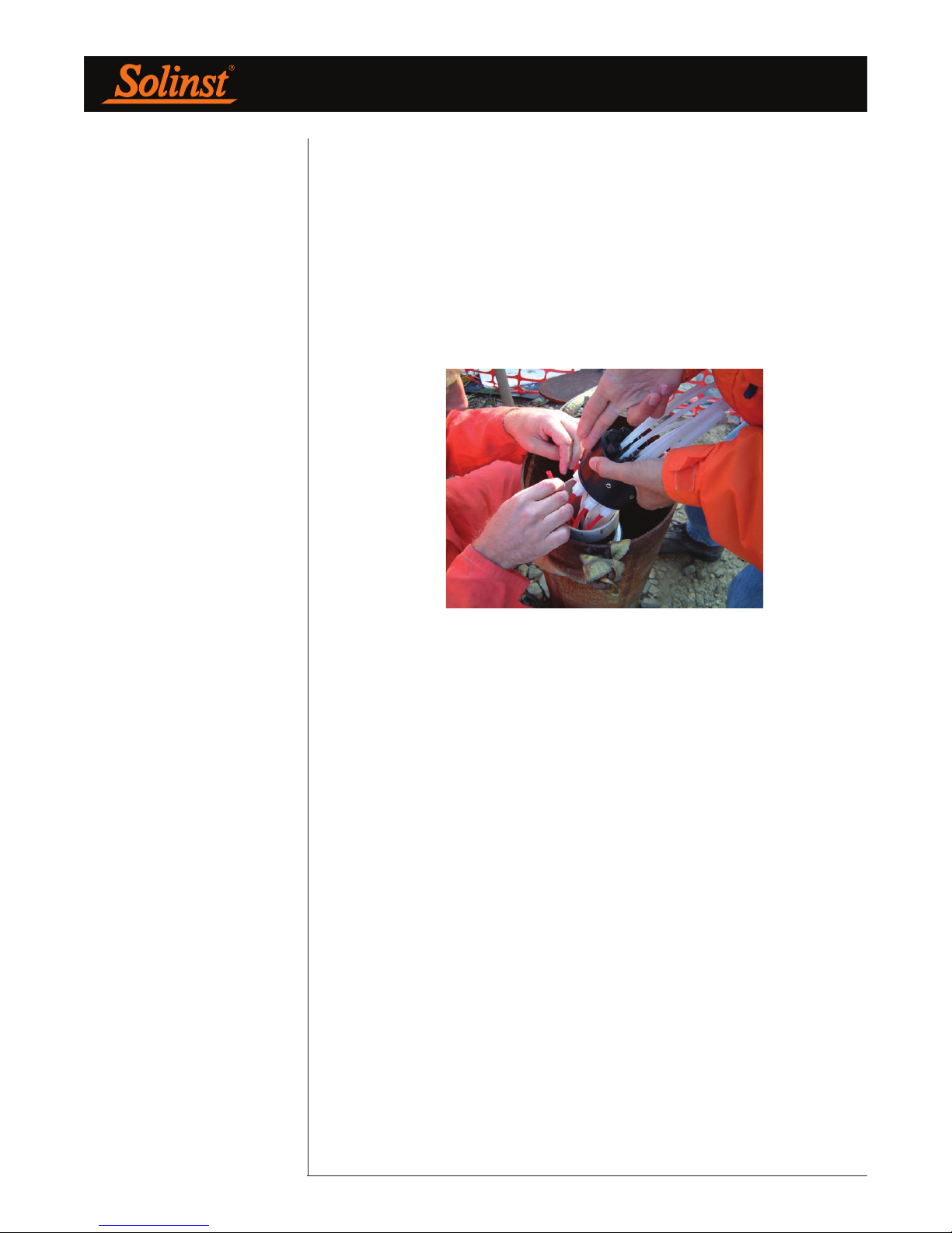
If pumps are used, follow the steps above, but before attaching the Wellhead,
choose one drive line tube and hold it up against the 4” (100 mm) diameter
white protective housing which is at its final elevation at the wellhead. Trim
the red drive line tube at a point about 2” (50 mm) above the white protective
housing. Insert this tubing end into the white (translucent) plastic compression
fitting on the base of the numbered Wellhead. You should be able to see the red
tubing pass through this fitting. Hand tighten the fitting. Repeat this procedure
on the remaining drive tubes. Re-attach the numbered Wellhead to the Manifold
Housing at the Wellhead and tighten the screws.
Figure 9-3 Pump Tubing Being Attached to a Wellhead
Page 19
Page 24
Waterloo Multilevel System Assembly Manual
9.3 Wellhead Protection
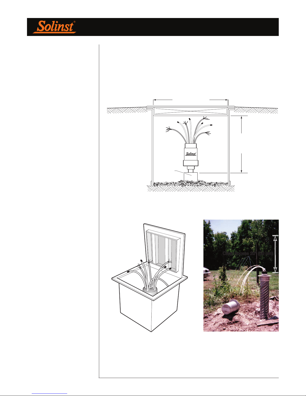
Allow sufficient wellhead access when you install a protective cover over the
well. Use a large well cover to allow plenty of room to access the wellhead. The
following diagrams show some suggested completions for the 401 Multilevel
System. These enclosures are not available at Solinst, however they are available
from most drilling contractors.
Min. 24" (60cm)
20" (50 cm)
Min.
Steel
Casing
Waterloo Multilevel Wellhead Inside Flushmount Vault
Figure 9-5
Typical Road Box or Vault
Figure 9-4
Clear Access 20” (50 cm)
Figure 9-6
Above ground completion
Minimum 6” dia. (15 cm) and
20”(50 cm) clearance is required
Page 20
Page 25
Waterloo Multilevel System Assembly Manual
10.0 Monitoring Options
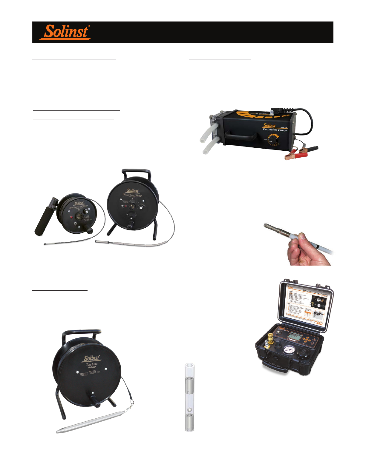
Water levels and samples can be accurately obtained using
the following high quality Solinst instruments:
Water Level Measurement
Model 102 Water Level Meter
The narrow coaxial cable Model 102 Water Level Meter
and 102M Mini Water Level Meter with a 0.157" (4 mm)
diameter P4 Probe can be used to monitor water levels in
open tubes. The coaxial cable is accurately laser marked
every 1/100 ft or mm.
Sampling Methods
Depending on the depth to water at your site, and your
sampling protocol, Solinst offers various sampling options.
Model 410 Peristaltic Pump
Ideal for sample retrieval from shallow water levels less than
30 ft. (9 m).
Model 408M (3/8" Dia.)
Micro Double Valve Pump
The Small and flexible design makes this gas drive pump
ideal for delivering high quality samples, in combination with
the Model 466 Electronic Control Unit. Flow rates of 20 to
150 mL/min make the 408M suitable for low flow sampling
applications. Constructed of stainless steel and PTFE tubing
for any depths up to 240 ft.
(73 m) applications. This is
the only viable option in wells
with depth to water over
150 ft. (45 m).
Well Completion
Model 103 Tag Line
The Tag Line is ideal to aid accurate placement of sand
and bentonite during borehole completion.
Model 464
Electronic Control Unit
Durable & easy to operate with
the 408M by using the presets
and fine tuning capabilities
built into the Solinst Model
464 Electronic Control Unit.
Mini Inertial Pump
This Mechanical pump uses 1/4" LDPE tubing.
Typical flow rates of 50 to 250 ml/min. Suitable for
use to depths of approximately 150 ft. (45 m). If the
water level on your site is deeper than 50 ft. (15 m),
PTFE tubing is recommended.
Page 21
Page 26
Waterloo Multilevel System Assembly Manual - Appendix
Page I
Page 27
Waterloo Multilevel System Assembly Manual - Appendix
Page II
Page 28
Waterloo Multilevel System Assembly Manual - Appendix
Sample Calculation
Converting a VWT reading from the GK-404 to a depth to water
In our example, let's assume the VWT is connected to a monitoring port that is located at a depth of 100 ft (30.48 m)
below ground surface.
From the GK-404 readout:
Zero Reading (pre installation) of VWT: 9978 digits
Submerged Reading of VWT: 7978 digits
Difference between Zero Reading & Submerged Reading: 2000 digits
From the "Vibrating Wire Pressure Transducer Calibration Report" (sample in Appendix III), locate the "Linear Gage
Factor" for each specific transducer serial number. In our example:
To calculate the pressure head (psi or kPa) on the VWT, multiply the appropriate "Linear Gage Factor", by the
difference between the zero reading and submerged reading. From our example:
0.006986 (psi/digit) x 2000 digits = 13.972 psi (96.33 kPa)
Therefore, VWT serial number 06-5822 has a pressure head of 13.972 psi (96.33 kPa).
To calculate the depth to water, simply convert psi (kPa) to feet (meters):
13.972 psi x 2.307 foot of head/psi = 32.23 feet of head.
96.33 kPa x 0.1020 meter of head/kPa = 9.826 meters of head
Now subtract the depth to the Port inlet (100ft/30.48m) from the pressure head.
100 ft - 32.23 feet of head = 67.77 ft.
30.48 m - 9.826 meters of head = 20.65 m
Page III
Page 29
Waterloo Multilevel System Assembly Manual - Appendix
Page IV
 Loading...