

Page 1
TLC Meter Faceplate Replacement Instructions
Tools and Materials Needed
1. 107 SC1000 Faceplate Assembly (spare) for the
TLC Meter (#107719)
2. Phillips or Robertson Screwdriver
3. Soldering Wire and Iron
4. Small Flat Screwdriver
5. Socket Screwdriver (or 10-32 Hex Key)
6. External C-Ring Pliers
7. Any Available Plastic Adhesive/Sealant (e.g. silicone)
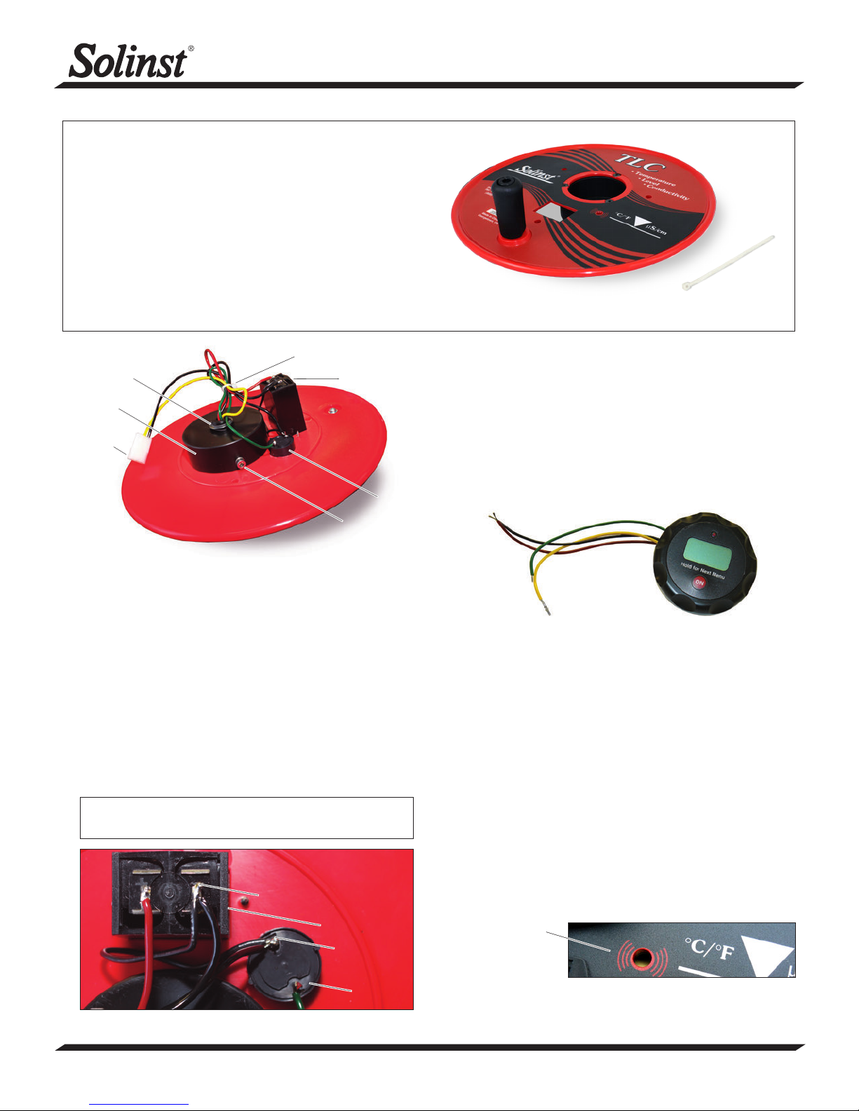
Model 107
Front of the Model 107 TLC Meter Replacement Faceplate
Cable Tie
Retaining Ring
Display
Retainer
Molex
Connector
Battery Tray
Sonalert
#10-32
Screw and
Washer
Back of the Model 107 TLC Meter Faceplate
Instructions
1. Place the reel on a flat workbench with the faceplate up.
Make sure the TLC Meter is turned off. Remove the battery.
2. Undo the three screws from the faceplate, and slowly
remove it from the reel.
3. Disconnect the white Molex connector inside the reel hub.
4. Cut the cable tie that is wrapped around the wires in the reel
hub.
5. Using the soldering iron, unsolder the wires from the
connections on the battery tray and Sonalert.
6. Pull to remove the Sonalert from the faceplate, noting the
position of the positive and negative pins (negative pin
beside the battery tray).
Note: Removing the Sonalert will require a small amount of force,
as the Sonalert is attached to the faceplate with sealant.
Negative Pin
Battery Tray
Negative Pin
Sonalert
Unsolder the Wire Connections and Note the Pin Positions
7. Undo the two screws holding the battery compartment and
remove it from the faceplate.
8. Push the two pins (on black and yellow wires) out of the
Molex connector.
9. Using the socket screwdriver, unscrew the #10-32 screw
and washer from the display retainer.
10. Using the external C-ring pliers, remove the washer and
retaining ring from the display retainer.
11. Push the display assembly and attached wires through the
front of the faceplate.
Display Assembly
12. From the front of the new faceplate assembly, feed the
wires of the display assembly through the opening in the
display retainer. Position the display assembly in the display
retainer until the base of the display assembly (rotating part
of the assembly) becomes flush with the front of the new
faceplate.
13. Refasten the #10-32 screw and washer to the display
retainer.
14. Position and refasten the washer and retaining ring using
the external ‘C’ ring pliers.
15. Insert the battery tray into the opening in the new faceplate
(ensure it is facing the right way). Secure it to the faceplate
using the two screws.
16. Apply a thin layer of plastic adhesive to the flat end of
Sonalert. Avoid getting any adhesive in the hole.
17. Line up the hole in the Sonalert with the hole in the new
faceplate and apply the Sonalert to the back of the faceplate
(negative pin beside the battery tray).
Clear away any
excess adhesive
from the hole in the
front of the TLC
Meter faceplate.
18. From the front of the faceplate, clear away any excess
adhesive from the hole. Allow sufficient time for the adhesive
to set.
Continued overleaf...
(Page 1 of 2)
High Quality Groundwater and Surface Water Monitoring Instrumentation
Page 2
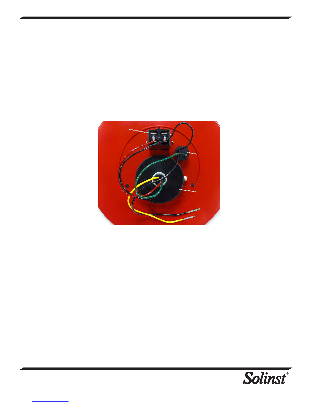
19. Looking at the photo below, resolder the wires to the
appropriate pins:
i) Solder the shorter black wire to the negative pin on the
Sonalert and the other end to the negative pin on the battery
tray.
ii) Solder the black wire from the display assembly to the
negative pin on the battery tray.
iii) Solder the red wire from the display assembly to the positive
pin on the battery tray.
iv) Solder the green wire from the display assembly to the
positive pin on the Sonalert.
v) Solder the longer black wire to the negative pin on the
Sonalert (opposite end will still have a Molex pin connected).
Battery Tray
Sonalert
Display
Assembly
Back of the TLC Meter Faceplate Showing Soldered Connections
20. Insert the yellow wire with the Molex pin back into the Molex
connector. The pin is inserted into the middle terminal of
the connector.
21. Insert the black wire with the Molex pin into the terminal on
the pointed side of the Molex connector (the third terminal
is left unused).
22. Reconnect the Molex connector to the connector on the
tape inside the reel hub.
23. Tie all the wires together with the new cable tie.
24. Replace the battery in the TLC Meter.
25. With the Probe in a glass of tap water, turn the TLC Meter
‘ON’. If the buzzer or light do not activate, or the LCD does
not show temperature or conductivity, check the soldered
and Molex connections.
26. Secure the new faceplate to the reel with the three screws.
Note: Conductivity calibration is not required, but is an option.
See the TLC Meter Operating Instructions for the calibration
procedure.
®
Solinst is a registered trademark of Solinst Canada Ltd.
Printed in Canada
September 23, 2013
(#111238)
(Page 2 of 2)
35 Todd Road, Georgetown, Ontario Canada L7G 4R8
Web Site: www.solinst.com E-mail: [email protected]
For further information contact: Solinst Canada Ltd.
Fax: +1 (905) 873-1992; (800) 516-9081 Tel: +1 (905) 873-2255; (800) 661-2023
 Loading...