

Page 1
Water Level Meter Faceplate with Electronics Replacement
Tools and Materials Needed
1. One of the following Replacement Mk2 Faceplates
with Electronics
• #112765 - 101 P7 SC1000 Faceplate w Electronics
• #112759 - 101 P7 SC2000 Faceplate w Electronics
• #112670 - 101 P2 SC1000 Faceplate w Electronics
• #112656 - 101 P2 SC2000 Faceplate w Electronics
• #112020 - 102 SC1000 Faceplate w Electronics
• #111921 - 102M SC100 Faceplate w Electronics
2. Phillips or Robertson Screwdriver
3. Wire Cutters (only required for Mk1 Water Level Meters –
see photo below)
4. Pliers (only required for Mk1 Water Level Meters –
see photo below))
Instructions
1. Place the reel on a flat surface, with the faceplate up.
Remove the battery from the Meter.
Note: The battery is located inside the reel hub of a 102M Water Level
Meter. Remove it in step 2.
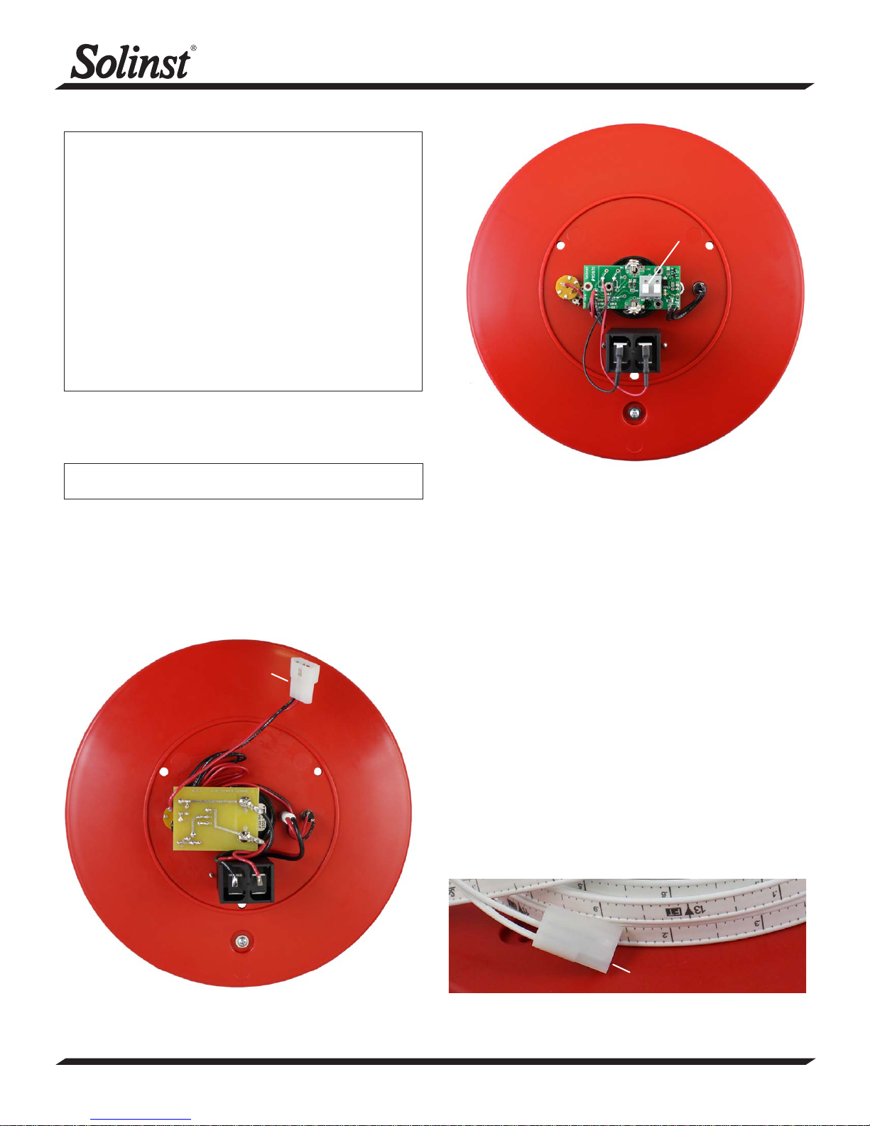
Model 101/102
Push-Release Fittings
Back of Mk2 101 Water Level Meter Faceplate
2. Use the screwdriver to undo the three screws holding the
faceplate to the hub. Remove the faceplate.
3. If this is a Mk1 Water Level Meter, disconnect the Molex
connector that connects the circuit board to the tape/cable.
If this is a Mk2 Water Level Meter, press down on the white
terminals of the push-release fittings on the circuit board
and pull out to remove the tape/cable leads.
Molex
Connector
4. To connect the new faceplate with electronics, connect the
tape/cable to the new circuit board assembly:
a) If this is a Mk2 Water Level Meter, press down
on the white terminals on the circuit board and insert
the tape/cable leads. Release the terminals and the
leads should be secured.
For 101 Water Level Meter, the lead on the bottom of
the tape (numbers facing up) is inserted into the
terminal with a white square below it on the circuit
board (see next page for images).
For 102 Water Level Meters, the positive lead is
inserted into the terminal with a square etched
below it on the circuit board. The positive lead has
the pin connected to insulated wire, the negative pin is
connected to the braided wire.
b) If this is a Mk1 Water Level Meter, with a Molex
connector on the tape/cable leads, remove the Molex
connector by pushing out the two pins. Cut each pin
in half (see image on next page for correct location).
Use pliers to flatten the remainder of the pins against
the tape/cable lead, so it fits easily into the terminals
on the circuit board. Connect each tape/cable lead to
the new circuit board assembly, as described above in
step a.
Back of Mk1 101 Water Level Meter Faceplate
(Page 1 of 2)
High Quality Groundwater and Surface Water Monitoring Instrumentation
Molex Connector
Remove the Pins from the Tape Molex Connector (Mk1)
Continued overleaf...
Page 2
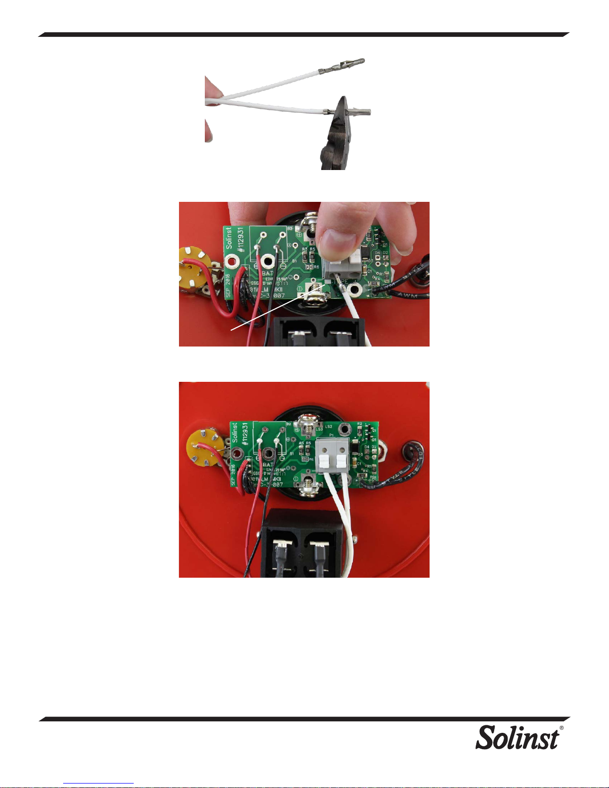
Cut the Pins on Each Tape/Cable Lead in Half (as shown)
Square
Press Down on the White Terminals on the Circuit Board and
Insert the Tape/Cable Leads
Release the White Terminals and the Leads Should be
Secured.
5. Install the battery.
6. With the probe in a glass of tap water, turn the Water Level
Meter to the ‘ON’ position. If the connections are correct
the buzzer and light will activate. If the buzzer or light do
not activate, check all connections and the polarity of the
battery.
7. Reattach the faceplate to the reel using the three screws.
Printed in Canada
June 5, 2018
(#113261)
(Page 2 of 2)
35 Todd Road, Georgetown, Ontario Canada L7G 4R8
Web Site: www.solinst.com E-mail: [email protected]
For further information contact: Solinst Canada Ltd.
Fax: +1 (905) 873-1992; (800) 516-9081 Tel: +1 (905) 873-2255; (800) 661-2023
 Loading...