

Page 1
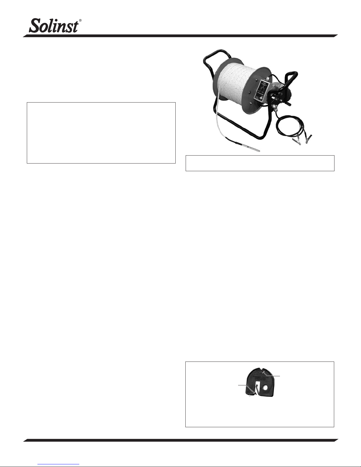
12V Power Reel Operating Instructions
Operation of the Controller
1. Set the speed dial on zero.
2. Connect to a 12V DC power supply using the clips provided.
3. Slowly turn the speed dial clockwise or counterclockwise
until the motor just starts to turn.
Model 101
Caution: Motor must be grounded in accordance with the
national electrical code and local codes by trained
personnel to prevent serious electrical shocks.
Ensure the air in-take fan at the end of the motor is
clear.
If down-hole component gets stuck, do not use power
motor. To avoid injury, turn motor off immediately,
and attempt retrieval manually.
Lowering the Tape
When lowering the tape, the speed will be about 2 ft/s,
increasing by 2 ft/s for each additional 1000 ft of tape downhole. To reduce the speed increase during lowering, turn the
speed dial down gradually. If the speed dial is at its lowest
setting (1) and the speed is still too fast, decrease the speed
by reversing the reel direction (i.e. rewind). This serves as a
dynamic brake, and enables you to stop at the desired depth.
Retrieving the Tape
When rewinding the tape, the speed also depends on the length
of tape down-hole. At maximum depth (for longer tapes with
5000 ft down-hole), the speed will be less than 0.2 ft/s, even
at the maximum speed setting (8). The speed will gradually
increase to 2 ft/s as the tape winds closer to the top of the well.
Controller
Input Ratings
10 - 16V DC @ 25A
Front Panel Controls
Speed dial: starts and stops motor, adjusts motor speed and
direction of rotation
Reset: 25A rating
Ambient Temperature Conditions
Temperature: 0 - 40˚C
Humidity: 90% RH or less, non-condensing
Motor
Lubrication
The shaft bearings contain grease fittings. After one year,
insert multipurpose chassis grease, and re-apply once per
year. The gear box is lubricated for life, and should never
need to be lubed.
Servicing
Disconnect power source from motor and any accessory
devices and allow motor to come to a complete stand still
Note: The Power Reel can use heat embossed polyethylene flat
tape or Solinst laser-marked PVDF flat tape
Water Level Meter Operation
Equipment Check
1. The level of sensitivity can be adjusted higher or lower by
turning the switch clockwise or counter clockwise.
2. Depress the Battery Test button to test the battery and
circuitry.
3. Submerse the probe in tap water. This completes the circuit
and activates the buzzer and light.
Water Level Measurement
The zero measurement point is at the tip of the sensor pin,
located at the centre of the P2 Probes, and where the black
Delrin tip meets the stainless steel body of the P7 Probes.
The light and buzzer activate when the zero point enters water.
To ensure accuracy, lower and raise the probe a few times and
then record the depth measurement from the tape at the top
of the well.
Using the Tape Guide
Feed the tape into and out of the well using the groove in the
top of the Tape Guide.
The tape guide has been designed to:
• improve accuracy when reading water levels,
• easily obtain repeatable measurements,
• prevent tape being cut by well casing,
• allow the tape and probe to hang straight from the side of
the well.
Tape Guide
Measurement Point
Fit onto well
casing
When using the tape guide, the measuring point is offset from
the top of casing. To adjust your measurements to the top of the
casing, simply subtract the amount indicated on the front of the
tape guide (i.e. 6 cm or 2/10 ft.).
® Solinst is a registered trademark of Solinst Canada Ltd
(Page 1 of 2)
High Quality Groundwater and Surface Water Monitoring Instrumentation
Continued overleaf...
Page 2
Routine Care
1. After the depth to water has been recorded, the tape should
be carefully rewound onto the reel, the probe wiped dry and
placed into the probe holder.
2. The probe, tape and reel can be cleaned with phosphate
free (non-abrasive) detergent and warm water.
3. Remove any dirt or water from around the central sensor
pin. If the central sensor pin is corroded or coated, use
emery cloth to polish it.
4. Check the P2 probe seal/strain relief and replace the black
heat shrink if there is any cracking or other damage.
5. Use of the Tape Guide adds to the life of the tape.
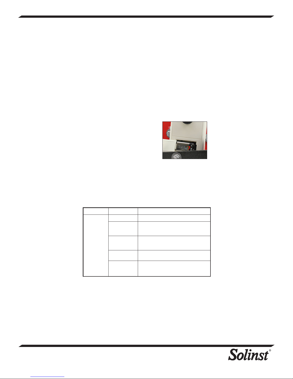
Battery Replacement (battery type - alkaline, 9 volt.)
1. The battery is housed conveniently
on the front of the grey box with
the sensitivity switch.
2. To replace the battery, open the
compartment with a screw driver.
3. Note the polarity and place a new
battery in the compartment. Snap
the compartment cover back into
place.
Replacement Parts
The following parts can be provided should they become lost
or damaged:
Probes and seal kits, splice kits, lights, switches, etc., reels, and
replacement tape with probes (complete) or probe seals.
SYMPTOM CAUSE REMEDY
No sound
when
probe
immersed
in water
®
Solinst is a registered trademark of Solinst Canada Ltd.
Printed in Canada
November 16, 2012
(#110370)
(Page 2 of 2)
35 Todd Road, Georgetown, Ontario Canada L7G 4R8
Web Site: www.solinst.com E-mail: [email protected]
For further information contact: Solinst Canada Ltd.
Fax: +1 (905) 873-1992; (800) 516-9081 Tel: +1 (905) 873-2255; (800) 661-2023
Dead battery. Replace with 9V Alkaline.
Water
conductivity is
very low.
Disconnected
wires on circuit
board.
Broken wire in
tape.
Disconnected
wire inside
probe.
Increase sensitivity switch setting (turn
clockwise) or call Solinst for assistance.
Check all connections inside hub of reel
for loose/disconnected wires - solder or
reconnect.
Locate break in tape - splice and seal
(contact Solinst).
Contact Solinst to obtain parts/repair
instructions.
 Loading...