


BiG SiX
User Guide
www.solidstatelogic.com
BiG SiX

Visit SSL at:
www.solidstatelogic.com
© Solid State Logic
All rights reserved under International and Pan-American Copyright Conventions
®
and Solid State Logic® are ® registered trademarks of Solid State Logic.
SSL
BiG SiX™, SiX™ and SuperAnalogue™ are trademarks of Solid State Logic.
All other product names and trademarks are the property of their respective owners and are hereby acknowledged.
No part of this publication may be reproduced in any form or by any means, whether mechanical or electronic,without the written
permission of Solid State Logic, Oxford, OX5 1RU, England.
As research and development is a continual process, Solid State Logic reserves the right to change the features and
specications described herein without notice or obligation.
Solid State Logic cannot be held responsible for any loss or damage arising directly or indirectly from any error or omission in
this manual.
PLEASE READ ALL INSTRUCTIONS, PAY SPECIAL HEED TO SAFETY WARNINGS.
E&OE
November 2021
Revision History
Revision V1.0, September 2021 - Initial Release
Revision V1.1, November 2021 - Updated 'Sum to Mix Bus' details
Revision V1.2, November 2021 - Updated compressor details

Introduction to BiG SiX
In the mid '70s Solid State Logic designed the rst A Series Console and Studio Computer. The idea behind the project was to
build a system for the company’s studio which was buried deep in the Oxfordshire countryside, in a small village called Stoneseld.
SSL’s development of advanced analogue mixing consoles has been continuous since those early days.
As the name implies, BiG SiX is the natural expansion of SSL’s successful SiX desktop console. Both BiG SiX and SiX are studio
grade, SuperAnalogue consoles that deliver all of the quality and exibility audio professionals expect from SSL, but in very
compact footprints. SiX is designed to be small enough to t into hand luggage or a half 19” rack space, BiG SiX is over twice the
size, ts a full 9U of 19” rack space and has many additional features, but with the same focus on audio quality and exibility of use.
Like SiX, but bigger...
BiG SiX is the big sister to SSL's acclaimed SiX console. Although both BiG SiX and SiX are small by SSL standards they carry
the same values and inherited DNA. What follows are some of the key elements that make BiG SiX a professional product for the
highest quality audio applications.
Fully balanced inputs and outputs
All of BiG SiX’s inputs and outputs are fully balanced (with the exception of the Phones output). This means professional equipment
with balanced connections can be properly interfaced allowing longer cable lengths without noise/hum pick-up penalties and the
best signal to noise performance from the whole signal chain.
Short is beautiful…
To provide the purest audio signal paths, BiG SiX has several features not normally found on small footprint mixing consoles e.g.
the channel processing is switched, allowing it to be removed from the signal path if it’s not being used. It’s denitely worth taking
some time to understand the BiG SiX block diagram and reading the examples later in this manual. We hope you’ll really unlock
the versatility of the console when discovering the many signal paths that are available and the multiple ways they can be used.
Meter scales and response
The upper LED meter points on BiG SiX’s main meters have been carefully chosen. The console is designed with a huge +27
dBu headroom and the meters have dened segments for +24 dBu and +18 dBu, this is to match the two most common 0 dB
Full Scale (dBFS) alignment standards, i.e. European/EBU at 0 dBFS=+18 dBu and the US/SMPTE standard at 0 dBFS=+24 dBu
ensuring optimum performance for converters and proper gain structure throughout the signal chain. The meters in BiG SiX have
been designed with a fast ‘peak’ response (rise time to 60% Full Scale Deection approx 1 ms @ 1 kHz) and a slower release time
to give the ability to meter fast peaks while still being able to show useful signal levels.
Converter alignment levels
The sixteen A to D and D to A converters in BiG SiX are aligned for 0 dBFS=+24 dBu to give the optimal performance from the
console's dynamic range.
Power and power management
You will have noticed that BiG SiX is powered by an external power supply with a multipin connector. This signicantly helps the
design and performance of BiG SiX. It moves the power supply's electromagnetic interference away from the SuperAnalogue
circuits inside BiG SiX. This allows us to design the internal electronics to have a bandwidth as wide as possible and thus deliver
the great phase and transient response SSL large format console users have come to expect in a very small footprint package.
Another thoughtful design feature for an analogue console is how the power rails are ramped on power-up to minimise thumps
on monitor and headphone outputs.

This Page Is Intentionally Almost Blank!
BiG SiX User Guide

About SuperAnalogue
SSL’s SuperAnalogue technology is the sum of an applied design philosophy, constant invention, and dedication to optimising
every detail of our precision audio products. There are many contributing aspects, including our bespoke circuits, ground-breaking
low-noise gain control, servo-coupled amplier stages, and many more. The design of BiG SiX is unique amongst small footprint
mixers in that it uses SuperAnalogue technology to bring large console sonics and processing into a very compact design.
Listed below are some of the main benets SuperAnalogue philosophy brings to BiG SiX.
Wideband audio
Typically a 20 kHz upper frequency limit is recognised as adequate for audio. A lucky few people can identify frequencies beyond
20 kHz. However, there is a secondary hearing mechanism, directly related to ‘rise-time’ (the transient performance of components)
and evidence to show that even though the basic frequency spectrum of human hearing degrades over time, our sensitivity to
rise-times does not. In addition, Transient Intermodulation Distortion (TIM) is a real - if difcult to measure - issue that brings high
frequency ‘waste’ to bear on the audible spectrum in poor or bandwidth-limited designs. Feedback paths in amplier circuitry are
a good example. For fast, accurate rise times and low TIM, SSL implements precision, high-frequency analogue technologies and
tests everything to better than 80 kHz. BiG SiX’s main signal path frequency response extends to beyond 100 kHz.
Elimination of signal path electrolytic capacitors
The physical construction of electrolytic capacitors means that their performance is imprecise and they are vulnerable to
electromagnetic interference so even expensive ‘high-quality’ electrolytics do not meet our standards. In addition, over time and
with temperature variations, electrolytic capacitors degrade and become ‘leaky’ resulting in signicant noise issues, altered sonic
character, and shortened product life. SSL avoids using electrolytic capacitors for decoupling between analogue stages wherever
possible. Instead we use advanced DC servo coupling techniques for wide bandwidth, low noise and high precision DC offset
control.
Discrete design and innovation
Many modern analogue audio products are the result of the ‘cookbook’ approach where off-the-shelf blocks are strung together to
full a practical brief, but lack the additional details that take them from functional to fantastic. To do that, you have to understand
how to augment commercially available components with discrete elements, do original research and sometimes even design
your own components.
SSL does not do ‘data-sheet design’ and continues to optimise and improve upon data-sheet specications and ‘serving
suggestions’ - we have even licensed our advances back to semiconductor manufacturers. BiG SiX represents the cumulation
of over 40 years of experience and expertise in improving the canon of analogue music electronics to continually exceed and
progress our own high standards.
Not one component, a whole design philosophy
Our philosophy is simple, we spare nothing in designing and manufacturing the best precision music tools available anywhere.
There is no single magic stage in BiG SiX - everything from the pre-amps through the line level electronics, signal processing and
output stages plays its part.
BiG SiX User Guide

Table of Contents
Introduction ..........................................................................................................................................1
Unpacking ....................................................................................................................................................................... 2
Safety Notices .................................................................................................................................................................2
Heat & Ventilation and Rack Mounting Option ................................................................................................................ 2
USB-C Digital Interface ...................................................................................................................................................3
USB Cables & Power ....................................................................................................................................................................3
USB Hubs .....................................................................................................................................................................................3
USB Drivers, Mac and Windows. ..................................................................................................................................................3
Console Overview ................................................................................................................................ 4
Front panel ......................................................................................................................................................................4
Rear Panel ....................................................................................................................................................................... 5
Detailed Description ............................................................................................................................7
SuperAnalogue Mono Channels .....................................................................................................................................7
SuperAnalogue Pre-Amp input .....................................................................................................................................................7
Mic Input (XLR) .............................................................................................................................................................................7
Line Input (¼” TRS) .......................................................................................................................................................................7
USB Return (From USB 'n') ...........................................................................................................................................................7
Channel EQ ...................................................................................................................................................................................8
Channel Compressor ....................................................................................................................................................................9
Channel Insert ...............................................................................................................................................................................9
Stereo Cue Sends .......................................................................................................................................................................10
Channel Fader and Pan ..............................................................................................................................................................10
USB Send....................................................................................................................................................................................10
Stereo channels ............................................................................................................................................................. 11
SuperAnalogue Stereo Input.......................................................................................................................................................11
Stereo Cue Sends .......................................................................................................................................................................11
Stereo EQ ....................................................................................................................................................................................11
Channel Fader and Pan ..............................................................................................................................................................11
USB Send....................................................................................................................................................................................11
Monitor section .............................................................................................................................................................. 12
MAIN and ALT monitor outputs...................................................................................................................................................12
Headphone (Phones) outputs .....................................................................................................................................................13
Monitor Source section ...............................................................................................................................................................13
External 1 and 2 Levels...............................................................................................................................................................13
Stereo Cue Master Section (including Talk Input) ......................................................................................................... 14
Talk Input Pre-amplier and LMC ...............................................................................................................................................14
Talk Input and LMC.....................................................................................................................................................................15
Artist Cue Mixes ..........................................................................................................................................................................15
Foldback Outputs as Effects Sends ...........................................................................................................................................15
Main Meter ..................................................................................................................................................................... 16
Bus B Master ................................................................................................................................................................. 16
Main Bus ........................................................................................................................................................................ 16
External to Main Bus Summing ...................................................................................................................................................16
Main Bus Insert ...........................................................................................................................................................................16
BiG SiX User Guide

SUM INPUT TO MAIN BUS ........................................................................................................................................................ 17
ST CUE 1 TO G COMP & SUM TO MAIN BUS .......................................................................................................................... 18
G-Series Bus Compressor .............................................................................................................................................19
USB-C Interface ............................................................................................................................................................20
USB Cables & Power ................................................................................................................................................................. 20
USB Hubs .................................................................................................................................................................................. 20
USB Drivers, Mac and Windows. ............................................................................................................................................... 20
USB Signal Routing and Block Diagram .......................................................................................................................25
USB Returns 1 - 16 (Signal ow from the DAW to BiG SiX) ....................................................................................................... 25
USB Sends 1 - 16 (Signal ow to the DAW from BiG SiX) ......................................................................................................... 25
Application Examples - Desktop Studio ........................................................................................................................28
Application Examples - Small Project Studio, Record/Overdub ...................................................................................30
Application Examples - Small Project Studio - Hybrid SuperAnalogue Mixdown .........................................................32
Application Examples - Post Production - ADR or Foreign Language Dubbing ...........................................................34
Application Examples - Podcast Studio ........................................................................................................................36
Troubleshooting & FAQs ................................................................................................................... 37
Troubleshooting Tips .....................................................................................................................................................37
Warranty ........................................................................................................................................................................38
All returns ................................................................................................................................................................................... 38
Appendix A - Physical Specication ................................................................................................39
Connector Details ..........................................................................................................................................................39
Mono Channels .......................................................................................................................................................................... 39
Stereo Channels......................................................................................................................................................................... 39
Insert Sends/Returns.................................................................................................................................................................. 40
DC Power Inlet ........................................................................................................................................................................... 40
Appendix B - Performance Specication ........................................................................................41
Audio Performance ........................................................................................................................................................41
SuperAnalogue Channel Microphone Amplier ............................................................................................................41
SuperAnalogue Channel Line Input Amplier ...............................................................................................................41
Channel Equaliser .........................................................................................................................................................42
Channel Compressor ....................................................................................................................................................42
SuperAnalogue Stereo Channel Line Input Amplier ....................................................................................................42
Overall Channel Signal Chain Specications ................................................................................................................43
Overall Console Noise ...................................................................................................................................................43
ADC and DAC Converter ..............................................................................................................................................43
Environmental Requirements ........................................................................................................................................43
Appendix C - BiG SiX Block Diagram ..............................................................................................44
Appendix D - Recall Sheet ................................................................................................................45
BiG SiX User Guide

Introduction
This Page Is Intentionally Almost Blank!
H
BiG SiX User Guide

Introduction
Introduction
BiG SiX is a studio grade, SuperAnalogue mixing console that delivers all of the quality and exibility audio professionals expect
from an SSL console, but in a package that is designed to t the compact footprint needed for smaller personal studios. Its
design doesn't compromise on performance because of its size, but delivers a powerful set of professional features in a 9U 19"
rack width package.
BiG SiX incorporates professional quality A to D and D to A converters and a multi-channel USB DAW interface, however the
connections and signal ow is such that it can be used as a wholly analogue mixing console, without reliance on the digital
connection.
Audio Excellence
➤ Four SuperAnalogue wide gain range mic pres for pristine recording quality
➤ Four wide gain range stereo line inputs
➤ Individually switchable phantom power on each Mic Input
➤ Line level input with true HiZ (1 MΩ) impedance switch for passive coil inputs (e.g. guitar pickups)
➤ Four recording channels with fully balanced inserts, simple three band SSL EQ and Dynamics and true bypass processing
switching
➤ Fast, accurate peak response LED meters
➤ Inbuilt 16 channel high quality AD and DA Converters with USB-C interface for DAWs
Mixing Versatility
➤ 18 channel stereo SuperAnalogue summing
➤ Main bus with fully balanced insert
➤ Simplied SSL Bus Compressor
➤ 100 mm studio grade long throw faders
➤ Stereo Mix Bus Summing Input to cascade mixing consoles.
Application Flexibility
➤ A ‘proper’ foldback section with two stereo send/cue buses with talkback, local monitoring plus two stereo cue feeds
➤ Versatile B-Bus/Mute switching provides record and mix buses for simple overdubs
➤ Useful, exible signal routing and summing
➤ Versatile ‘summing’ monitor section with two external source selectors
➤ Two Headphone Outputs with separate source selectors
➤ ‘Listen mic compressor’ with exible routing for studio talkback or more creative applications
BiG SiX User Guide
1

Introduction
Unpacking
The unit has been carefully packed and inside the box you will nd the following items.
➤ BiG SiX Console
➤ IEC power cord or cords (depending on territory)
➤ 1.8 m, 6 A IEC mains Cable - UK Plug (SSL Part # 32VGL3A1)
➤ 1.8 m, 6 A IEC mains Cable - EU Plug (SSL Part # 32VGL3A3)
➤ 1.8 m, 6 A IEC mains Cable - US Plug (SSL Part # 32VGL3A2)
➤ 1.8 m, 10 A IEC mains Cable - JPN Plug (SSL Part # 32VGL3J3)
➤ External Power Supply with multi-pin connector (SSL Part # 37147HHJ)
➤ 1.5 m USB-C to USB A cable (SSL Part # 66AURM20)
➤ 1.5 m USB-C to USB-C cable (SSL Part # 66AURM00)
➤ Safety Guide
➤ Quickstart Guide
➤ Registration card
It is always a good idea to save the original box and packaging, just in case you ever need to send the unit in for service.
Safety Notices
IMPORTANT: Please read the safety notice information included in the Safety Guide supplied inside the box before using BiG SiX.
Heat & Ventilation and Rack Mounting Option
BiG SiX packs a lot of SuperAnalogue electronics into its compact size. It is designed to get warm in normal operation. Please
consult the operational specications in Appendix B of this User Guide to make sure that it is used within its designed environmental
parameters.
Optional rack mounting kits to t a BiG SiX console within a standard 19-inch rack are available.
The rack mount kit has the SSL Part Number: 729752XR
Whenever rack mounted, or mounted in furniture, please ensure at least 1 inch (2cm) of ventilation space is left available in the
front and rear of the console. You will see the ventilation holes in the console chassis - these need to have clear airow to cool the
unit correctly.
2
BiG SiX User Guide

Introduction
USB-C Digital Interface
BiG SiX contains a class compliant USB interface to connect to a PC or MAC. The interface is paired with 16 high quality A to D
and D to A converters that are connected to the SuperAnalogue signal chain in BiG SiX.
USB Cables & Power
Please use one of the provided USB cables ('C' to 'C' or 'C' to 'A') to connect BiG SiX to your computer. The connector on the rear
of BiG SiX is a 'C' type. The type of USB port you have available on your computer will determine which of the two included cables
you should use. Newer computers may have 'C' ports, whereas older computers may have 'A'. As this is a USB 2.0 compliant
device, it will make no difference to the performance as to which cable you use.
BiG SiX is powered independently from the computer's USB-bus power. When the unit is locked to USB correctly, the green
USB LED will light a steady green colour. For best stability and performance, we recommend using one of the included USB
cables. Long and low quality USB cables (especially 3m and above) should be avoided as they tend to suffer from inconsistent
performance.
USB Hubs
Wherever possible, it is best to connect BiG SiX directly to a spare USB port on your computer. If you do need to connect via a USB
2.0 compliant hub, then it is recommended that you choose one of high enough quality to provide reliable performance - not all
USB hubs were created equal. With BiG SiX, we optimise the audio performance of a USB interface and as such, some low-cost
self-powered hubs might not always be up to the task. Usefully, you can check out our FAQs at solidstatelogic.com/support to
see which hubs we've successfully used and found to be reliable with BiG SiX.
USB Drivers, Mac and Windows.
Mac
The USB interface in BiG SiX is Core Audio compliant, which means it should be seen by a Apple's OSx software without the need
for any additional drivers. Core Audio was introduced by Apple in OSx version 10.3 (Panther), however the BiG SiX USB interface
has only been tested with Apple OSx version 10.14 (Mojave) or later.
Windows
Windows based PCs will need to install the SSL USB Audio ASIO/WDM driver, which can be found in the Support/Downloads
section of the SSL website at www.solidstatelogic.com/
More information about the use of the USB interface can be found in the USB section of this Guide.
Safety Notices
Please read the Important Safety Notices at the end of this User Guide before use.
System Requirements
Mac and Windows operating systems and hardware are constantly changing. Please search for 'BiG SiX Compatibility' in our online
FAQs to see if your system is currently supported.
BiG SiX User Guide
3
Console Overview
Console Overview
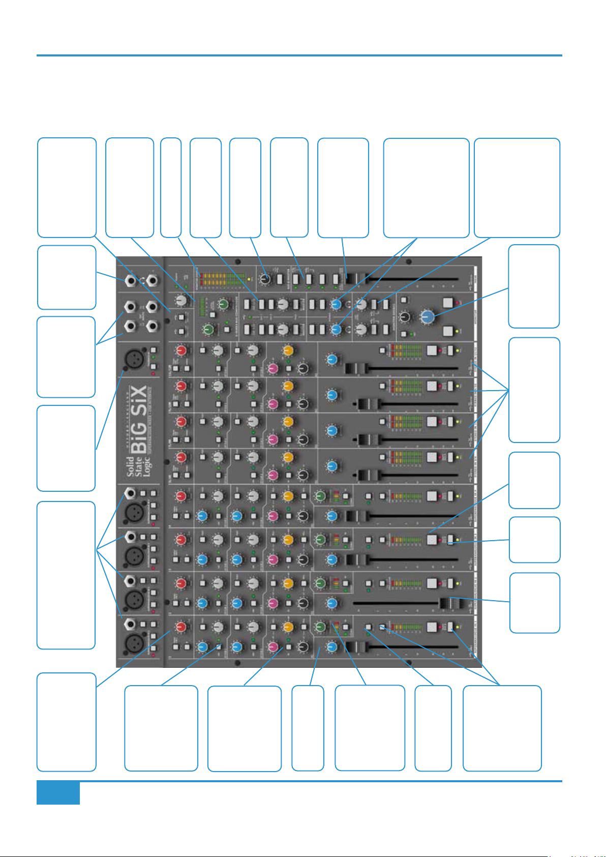
Front panel
Switches
Return Selector
External From USB
Two Stereo
Two Fully
Talkback
Talkback Level Master
Outputs
Headphone
Inputs
Balanced External
Switch
48V and LMC
Microphone Input,
Release Switch
SSL G-Series Bus
Compressor with Auto
12 LED Main Meter
and Mute
Summing Cue &
Foldback Masters
Bus B Master Level
Master Section
Summing Main Output
Parallel Mix Feature
with Cue/Bus Comp
100 mm Main Fader
Selector
Two Independent
Headphone Level
Controls and Source
Controls
Summing Monitor
External Input Level
Source Selector and
Control
Output Switch
Monitor Level and
Stereo Sends
SuperAnalogue Stereo
Channels with Switched
switch
Mute/Bus B
Microphone(XLR) or
Fully Balanced SuperAnalogue
Line (TRS Jack) Preamp Inputs
USB Source Select
Mic/Line Input Level
Polarity Invert Switch
switch, level and
Two Stereo Cues
switched with Post
4
pan controls
3 Band HF/MF/LF
HF & LF Bell
Frequency Shift
Curve with Centre
EQ with switchable
Channel Pan
Channel
Compressor with
switch and meter
Threshold control
Fully Balanced
Channel Insert
USB Channel
Output with Post
BiG SiX User Guide
PFL
switch
Fader
100 mm
Channel
Switch
Fader Option
Console Overview
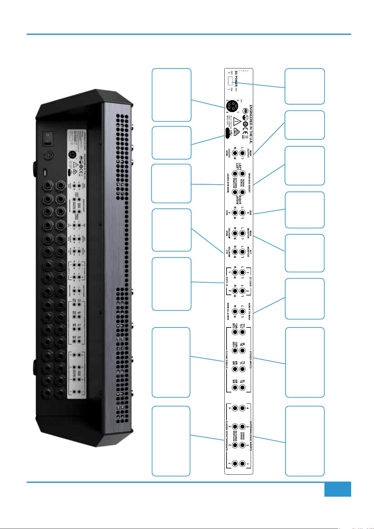
Rear Panel
The rear panel of SiX is shown below. The connectors are identied on a panel above the connector panel. All audio connectors
are Balanced TRS 1/4" Jacks.
(4 Pin mini DIN
Connector)
Connector
Connector
USB-C
Main Bus
Returns
Insert
DC Power
DC Power
Switch
Main Bus
Outputs
Insert Sends
Main Bus
Outputs
Bus B
Alternate
Outputs
Monitor
Stereo Cue 1 & 2
Outputs
Right Stereo Channel
Inputs
Main Monitor
Outputs
Bus Summing
Stereo Main
Inputs
Left Stereo Channel
Inputs
BiG SiX User Guide
Channel Balanced Insert
Returns
Channel Balanced Insert
Sends
5

Console Overview
This Page Is Intentionally Almost Blank!
6
BiG SiX User Guide

Console Overview
SUPER ANALOGUE IN (1 of 4)
BELL
BELL
LF
HF
EQ IN
T/HOLD
MF
Detailed Description
SuperAnalogue Mono Channels
There are four SuperAnalogue mono channels on BiG SiX; each channel has identical facilities. This
section explains the features found in each.
SuperAnalogue Pre-Amp input
BiG SiX’s pre-amp is a wide gain range SuperAnalogue design inherited from SiX and developed
from the mic pre-amps of the larger SSL Duality and AWS consoles. In these consoles, line and mic
inputs are served by separate pre-amps. In BiG SiX, a wide gain range, ultra low noise SuperAnalogue
design provides both Line and Mic facilities with a [Line] gain range switch to cover a wide range of
source levels.
The pre-amp consists of a microphone input (XLR) and line level input (¼” TRS Jack Socket).
Mic Input (XLR)
The default microphone input uses SSL’s SuperAnalogue design and includes individually switched 48 V phantom power. The Mic
(XLR) input’s nominal impedance is 1.2 kΩ.
Line Input (¼” TRS)
The XLR is the default source input, the source can be switched to the ¼” TRS jack line input by pressing the ‘LINE’ switch on the
channel. The nominal Line Input impedance is 10 kΩ this can be changed to 1 MΩ using the Hi-Z switch. This input impedance
makes this input suitable for very high impedance sources such as passive guitar pickups without the need for an external DI box.
The Gain control adjusts either the microphone pre-amp gain (+6 dB to +72 dB), or the Line amp gain (-3 dB to +63 dB), depending
on the selected input source. Following the pre-amplier is a switched 12 dB/oct, 75 Hz High Pass Filter (HPF) to reduce unwanted
LF such as Microphone Rumble, AC noise etc.
USB Return (From USB 'n')
These are the D/A Converter outputs from USB Returns 1-4 and they are selectable as unity gain inputs after the Mic/Line Pre-Amp
and are before the polarity invert and High Pass Filter (HPF) sections as shown in the block diagram below.
Input Section Block Diagram
GAIN
48V
MIC
+48V
1.2K
HI-Z
LINE
10K
LINE
1M
+dB
+6 to +72dB
[-3 to +63dB]
-9dB
USB
Ø
75 Hz
HPF
USB
RETURN
1..4
BiG SiX User Guide
7

Console Overview
Channel EQ
The channel EQ on BiG SiX has its roots in SSL’s classic E series EQ. It is a gentle, broad stroke
three-band design with high and low shelving lters at 3.5 kHz and 60 Hz, adjustable from +15
dB to -15 dB of gain and a xed Mid Frequency control at 700 Hz. The HF and LF bands can be
independently switched between shelving and bell curves using the BELL switch. A useful feature
of the bell curves is that they change centre frequency to operate at 5 kHz and 200 Hz giving
greater versatility from the HF and LF sections.
The EQ is switched 'in' circuit or completely bypassed using the IN switch. This small detail
guarantees no inuence on the channel’s exceptionally at frequency response from the tolerance
of the EQ control centre detent positions.
HF & LF Shelf & MF Frequency Response
HF & LF Bell & MF Frequency Response
8
BiG SiX User Guide

Console Overview
USB
Channel Compressor
The channel compressor in BiG SiX is an evolution of the design in SiX. As with the design in SiX, it is inspired
by the sophisticated channel dynamics sections of earlier SSL analogue consoles, but with some clever design
features to give powerful and versatile performance from its deceptively simple appearance.
The attack time of the compressor is somewhat program dependant and varies between approximately 8 ms
and 30 ms. This allows the compressor to operate smoothly when working with a wide variety of content. The
release time is approximately 300 ms and the ratio is a gentle 2:1. The knee of the compressor has been slightly
softened from the version in SiX to reduce artefacts on bass signals. The single user control is for the compressor
Threshold adjustable between +10 and -20 dBu and is accompanied with three LEDs indicating the amount of
gain reduction being applied. The circuit has automatic make-up gain to help maintain signal level for the full
range of threshold settings.
As with the EQ circuit, the compressor can be completely bypassed using the IN switch, providing a simple way to compare the
compressed and uncompressed signals. This also prevents component tolerances from inuencing the sound of the channel strip
when the Threshold is turned to minimum.
Channel Processing Overview
POST
FADER
USB
SEND
MAIN
BUS B
MIX AFL
1..4
L R
L R
L R
L R
MAIN
BUS B
MIC
LINE
USB
RETURN
1..4
48V
+48V
HI-Z
10K
GAIN
LINE
1.2K
1M
+6 to +72dB
[-3 to +63dB]
USB
+dB
Ø
-9dB
LF
MF
BELL
HPF
75 Hz
ST CUE 1
POST
POST
T/HOLD
HF
BELL
EQ IN
LEVEL
PAN
to 0dB
ST CUE 2
LEVEL
to 0dB
PFL
PFL
COMP
IN
SEND
+
-
ST CUE 2
MIX
ST CUE 1
L R
L R
L R L R
ON
ON
PAN
PFL
L R
RETURN
+
-
INSERT
PAN
Channel Insert
BiG SiX User Guide
Following the EQ and compressor in the channel signal ow is a fully balanced insert point. In common
with larger SSL consoles, the Insert Send is always active, while the Insert Return switches into the signal
path when selected.
The primary use of the insert is to bring external processing into the channel signal path. For example,
to insert a more surgical EQ or fully featured dynamics unit such as those found in SSL’s X-Rack or 500
series modules.
Another benet of this conguration and the unity gain design is that the Insert Send can be used as a
pre-fade, post-processing direct channel output to act as a record feed. This leaves the Insert Return
free to be used as a pre-fader/pre-pan path input by selecting the Insert IN switch and feeding a
separate line level signal into the Insert Return. This is the shortest signal path to the A/D converter for
the USB channel output connected to the SuperAnalogue channel.
The channel insert sends and returns are found on the dedicaed rear panel Channel Insert Send and
Return 1/4" balanced TRS connectors.
9
Console Overview
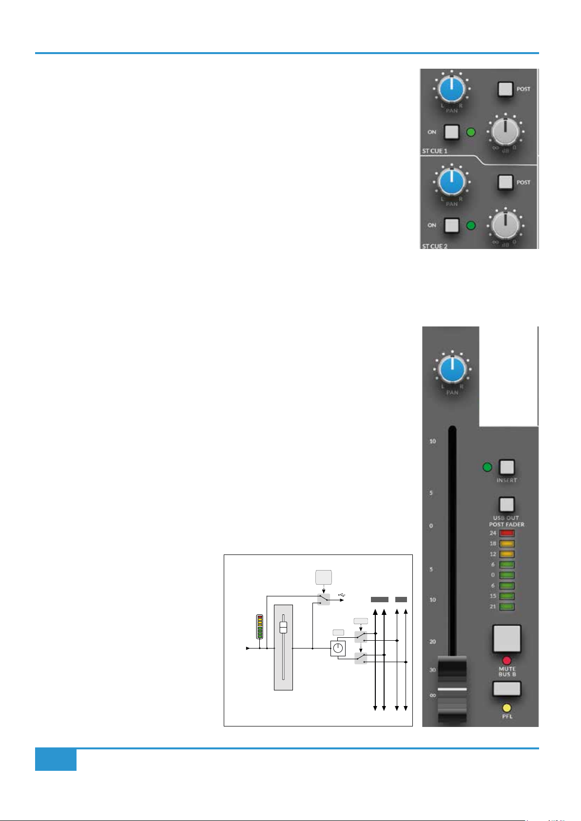
Stereo Cue Sends
Each mono channel can access two Stereo Cue sends with independent Level and Pan controls.
The ON switch sends the channel signal to the cue bus indicated by a green LED.
Both sends are fed from channel pre-fade, post-insert, but can be switched to Post Fader by
engaging the corresponding CUE POST switch in the Foldback master section.
The channel signal is unity gain to the Cue Bus when the Send Level control is fully clockwise
and the Pan control is hard left or right. The centre Pan level is -4.5 dB from 0 dB to each bus,
- a traditional SSL compromise between typical mono -3 and -6 dB centre points for constant
perceived level or power.
Channel Fader and Pan
The channel signal level is controlled by a high quality 100 mm fader. The Pan pot directly above this pans the signal to the Main
Mix Bus. Next to the Fader is the Channel Meter, as well as the channel Mute/Bus B switch and PFL switch.
The Fader law is designed to provide more resolution around the 0 dB point, allowing subtle level
changes from modest fader movements. The fader output is unity gain to the bus when the Pan
control is hard left or right. The centre Pan level is -4.5 dB from 0 dB to each bus.
The Mute/Bus B switch mutes the channel feed to the Main Mix Bus, whilst also sending the channel
signal post-fader to the additional stereo Mix Bus B.
The PFL (Pre Fade Listen) switch sends the channel signal to the PFL bus and interrupts the monitor
bus without affecting the main signal output to the Main Mix Bus.
The eight LED Channel Meter is fed from before the fader but after the channel processing. The fast
response peak meter has dened segments for +24 dBu and +18 dBu as well as 0 dBu. The meter
has a fast ‘peak’ response (rise time to 60% Full Scale Deection approx 1 ms @ 1 kHz), and a
slower release time to meter peaks while still showing useful signal levels.
USB Send
By default there is an A/D converter connected
to the USB Send Pre Fader output of each
SuperAnalogue channel strip. This can be
individually switched to Post Fader using the
USB OUT POST FADER switch. These USB
Sends are always post processing and so can
be used for per path outputs for recording in
a DAW.
The "TO USB n" legend at the base of each
SuperAnalogue channel fader shows which
USB send the channel is connected to.
FROM
CHANNEL
POST INSERT
RETURN
USB
POST
FADER
USB
SEND
1..4
PAN
MAIN
BUS B
MAIN
MIX AFL
L R
L R
L R
BUS B
L R
10
BiG SiX User Guide

Stereo channels
USB
SuperAnalogue Stereo Input
The inputs to the stereo channels are on ¼” TRS balanced jack connectors on the rear of the unit. These are
labelled 5L, 6R, 7L, 8R, 9L, 10R, 11L and 12R for the four pairs of inputs. Optionally the stereo channel inputs
can be switched from DA converters from relevant USB returns by selecting the USB switch at the top of the
strip. The USB input is before the input Trim gain control. The Trim control adjusts the stereo Line amp gain from
-10 to +20 dB with a centre detent at unity gain.
The rear TRS Jack inputs have an automatic ‘Mono From Left’ feature, i.e. if only a single jack connector is used
in the Left input, then the same signal is fed to the Right input. When a jack is inserted into the right input, the
Left and Right signals are passed separately through the channel. Additionally, there is a front panel MONO
switch which mono's both left and right inputs.
Stereo Cue Sends
There are two stereo Cue sends on each stereo channel with independent level controls. These can be switched
on or off using the ON switch; a green LED indicates that the Cue send is switched on.
Console Overview
The sends are fed from channel pre-fader post-insert, but can be switched to post fader with the individual
POST switches. The channel signal is unity gain to the Cue Bus when the Send Level control is fully clockwise.
Stereo EQ
The stereo EQ is similar to the channel EQ in that it's a gentle,
broad stroke three-band design with high and low shelving
lters at 3.5 kHz and 60 Hz, adjustable from +15 dB to -15
dB of gain and a Mid Frequency control centred at 700 Hz.
Channel Fader and Pan
The channel level is controlled by the 100 mm stereo fader,
with a Balance control directly above. This adjusts the balance between the left and right input signals to the
main mix bus.
POST
The Mute/Bus B switch mutes the channel feed to the Main
FADER
Mix Bus, whilst also sending the channel signal post-fader to
the additional stereo Mix Bus B.
The PFL (Pre Fade Listen) switch sends the channel signal
to the PFL bus and interrupts the monitoring to switch to this
bus without affecting the signal output to the Main Mix Bus.
FROM ST
CHANNEL L
BALANCE
The eight LED Stereo Channel Meter is fed before the fader,
but after the channel processing.
FROM ST
USB Send
CHANNEL R
By default there is a A/D converter connected to the the USB
Send Pre Fader output of each SuperAnalogue channel strip, for the stereo channel, these are conneced in odd/
even pairs, e.g. Send 5/6. The sends can be switched in pairs to Post Fader using the USB OUT POST FADER
switch.
TO
MIX/BUS B L
TO
MIX/BUS B R
USB
SEND
5,7,9,11
BiG SiX User Guide
11

Console Overview
ST CUE 1
Monitor section
The monitoring facilities in BiG SiX are very comprehensive given the size of the console. The block diagram below shows the
structure of the Main Monitor, Alternate Monitor and Headphone outputs.
L
MAIN
BUS
BUS
B
MON SOURCE
MIX
L R
L R
MON
MAIN
L R
BUS B
PFL
MONO
LEVEL
CUT
DIM
MONITOR
LEVEL
+
-
+
PHONES 1
LEVEL
to 0dB
PHONES 2
LEVEL
-
+
MIX
L R
L R
PFL
3dB
-3 to -30dB
to 0dB
ST CUE 2ST CUE 1
ST CUE 2ST CUE 1
ALT MON
R
ALT
L
MAIN MON
R
Headphone Jack 1
Headphone Jack 2
MIX
MIX
L R
L R
L R
L R
ST CUE 2
to 0dB
MAIN and ALT monitor outputs
The monitor section has two sets of balanced outputs for loudspeakers labelled MAIN MONITOR
and ALT MONITOR (See rear connector layout below). By default, the MAIN MONITOR output
is used. Pressing the ALT key on the front panel switches the Monitor feed to the ALT MONITOR
output. Both Main and Alt outputs use balanced ¼” jack Sockets on the rear connector panel.
The Monitor outputs are Off when the Monitor Level is fully anti-clockwise (0) and at unity when
fully clockwise (11).
Below the Monitor Level control are buttons for DIM and CUT. The CUT button mutes all of the
monitor outputs. The DIM button lowers the monitor output level as controlled by the DIM level
knob which is directly above the Monitor Level control in the Monitor Source section.
The MONO switch sums the monitor output to Mono with a -3 dB level drop.
BiG SiX Rear Connectors
12
BiG SiX User Guide

Headphone (Phones) outputs
In addition to the Main and Alt loudspeaker outputs, BiG SiX has two stereo headphone output on ¼” Stereo Jacks
on the upper connector panel above the Power indicator.
Each headphone level is independently controlled by the two PHONES knobs
above the Monitor Level control. By default, the headphone outputs follows the
MONITOR SOURCE selection. However, the headphone outputs can also be
switched to monitor Stereo Cue buses 1 & 2 independently of the Monitor selection,
using the ST CUE 1 and ST CUE 2 switches above the level controls. These
switches intercancel with the lower switch (CUE 2) taking priority. The Stereo Cue
feeds to these switches are after the additional features of the Foldback section,
i.e. after Talkback and the External Source selection. This allows these outputs to
be used for artist feeds, however care needs to be taken to prevent the Talkback
feeding back into the headphones when both the Foldback/Talkback Mic and the Headphone outputs are being
used.
Monitor Source section
The MONITOR SOURCE section controls the signals fed to the Monitor Level and the Headphone
Outputs. A block diagram of this section can be seen on the next page. A powerful and unusual
feature of the Monitor Source section is that the sources sum, rather than switch. This allows
monitoring of external signals alongside the main mix buses while using these buses to feed audio
recorders or other ‘clean’ feeds.
Console Overview
Buttons in the MON SOURCE section SUM signals into the monitor outputs as follows:
- MAIN - Main Bus - after fader, insert, compressor and source summing
- BUS B - Bus B after the level control and MUTE switch
- EXT 1 - External Input 1 after the level control
- EXT 2 - External Input 2 after the level control
The EXT inputs show a USB symbol, this is because the EXT inputs can be sourced from the USB
D/A returns. A pair of switches next to the TALK LEVEL knob allow the EXT 1 and EXT 2 signals
to be sourced from USB Returns 13/14 and 15/16 respectively. These switches over-ride the External Input TRS Jacks.
PLEASE NOTE: IF NONE OF THE ABOVE BUTTONS ARE SELECTED, THERE WILL BE NO SIGNAL TO THE
MONITORS
External 1 and 2 Levels
Above the EXT 1 and EXT 2 monitor source switches are the level controls for the relevant External inputs. These level controls
adjust the External level between off and +20 dB, with a detent at unity (0 dB). The law of these controls is designed to offer more
ne control around unity gain, with a greater degree of tapering in the level control law towards the end positions. The External
level set by these controls affects wherever the Ext signals are fed in the console (e.g. to the external summing into the Main Bus).
They also effect the level of the USB Returns, if selected.
The block diagram for the Monitor Source and External Input section is shown on the next page.
BiG SiX User Guide
13

Console Overview
Cue Outputs and External Inputs
EXT 1 TO
EXT 2 TO
MAIN
MAIN
L R
L R
USB RTN
L
USB RTN
13
EXT 1
R
USB RTN
14
L
USB RTN
15
EXT 2
R
USB RTN
16
13/14
TO EXT 1
USB RTN
15/16
TO EXT 2
EXT IN
LEVEL
+
-
+
-
to +20dB
LEVEL
+
-
+
-
to +20dB
EXT 1
EXT 2
L R
L R
MON
L R
CUE 1 TO
MON & B/C
CUE TO USB
L R
CUE 1 TO 9/10
STEREO
CHANNEL
USB FEEDS
9/10 & 11/12
MIX
MIX
L R
L R
EXT 1
CUE 1
L R
ST CUE 1
LEVEL
EXT 2
to +10dB
TALK
EXT 1
EXT 2
+
-
+
-
USB
SEND
9
USB
SEND
10
STEREO
CUE 1 OUT
MIX
L R
L R
CUE 2
L R
CUE 2 TO
MON
L R
1L
1R
ST CUE 2
LEVEL
to +10dB
+
-
+
-
CUE TO USB
CUE 2 TO 11/12
STEREO
CUE 2 OUT
USB
SEND
11
USB
SEND
12
2L
2R
TALK INPUT
TALK
LMC
48V
+
+48V
+45dB
-
+20dB
TB
IN
LEVEL
to 0dB
CUE OUTPUTS
Stereo Cue Master Section (including Talk Input)
The two Stereo Cue buses in BiG SiX feed the Stereo Cue Master section. This section is split
vertically with the left column controlling Stereo Cue 1 and the right controlling Stereo Cue 2.
The knobs in this section control the master level of the individual Cue outputs. As can be seen
in the block diagram above, they are the last controls before the output (i.e. after the selected
sources).
The upper switches in this section re-route the Cue Output via A/D converters to the relevant USB
Sends. These signals replace the outputs from the relevant Stereo Channels. i.e. the Switch CUE
1 TO USB 9/10 replaces the Stereo Channel USB Sends to USB 9/10 with the output of the Stereo
Cue 1 Master and similarly for the CUE 2 TO USB 11/12 switch. A green LED illuminates if either
switch is selected.
Three switches sum TALK, EXT 1 and EXT 2, with the following functions:
- TALK - sums the output of the Talk section with the Cue Bus to the selected Cue Output
- EXT 1 - sums the External Source 1 input with the Cue Bus to the selected Cue Output
- EXT 2 - sums the External Source 2 input with the Cue Bus to the selected Cue Output
Talk Input Pre-amplier and LMC
BiG SiX’s Talk Input is an additional pre-amplier and compressor circuit nominally designed to provide talkback facilities to the
Stereo Cue outputs of the console, but with several other possible applications when the design is explored more fully.
14
BiG SiX User Guide

Talk Input and LMC
The Talk input is a balanced female XLR connector. Below the connector
are switches for Phantom Power and the LMC. LMC is the legendary SSL
Listen Mic Compressor (here being used for Talkback, which is arguably
its original design purpose).
The Talk Input feeds a xed +45 dB high quality mic pre-amplier and
then optionally the LMC compressor. The LMC adds an additional
+20 dB of make-up gain to restore signal level after the severe amount
of gain reduction it introduces by design. The output level of the Talk
circuit is controlled by the TALK LEVEL knob.
The LMC circuit is designed to allow a microphone connected to the Talk
Input to maintain similar level signals regardless of whether the source
is close or distant. i.e. if an engineer is close to the console and another
person is sat on a couch behind the engineer, the artist will hear both of
their voices legibly and at a similar level.
Console Overview
The TALK key in the ST CUE master section latches to allow a secondary use of the Talk Input pre-amplier and compressor as
an effect, using the Cue send as the output.
Artist Cue Mixes
The master Cue features of BiG SiX are designed to provide a separate artist mix from the engineer’s monitoring and headphone
feed using the Mono and Stereo Channel’s Cue Send buses. Typically, the fully balanced outputs will be connected to a dedicated
Headphone amplier or Cue system, although there is enough level to drive many headphones directly with suitable wiring
(balanced left and right outputs wired to unbalanced left/right headphone connection).
The EXT 1 and EXT 2 switches in the Foldback master section provide a simple way to feed an external source to the Foldback
outputs. These are typically used when it would be useful to play something directly to the artist - for example a rough mix from a
phone/DAW.
Foldback Outputs as Effects Sends
It is perfectly feasible to use the Cue Outputs as stereo feeds to external effects processors such as delays and reverbs. Typically,
the processor’s output would be connected to one of the External returns, then summed to the main bus using the External
summing switches to the Main Bus above the Main Fader.
The CUE to USB feature provides a simple way to use effects in the DAW with send levels from BiG SiX. Similarly the USB to
External Input feature provides a way to bring wet/processed signals back from the DAW.
BiG SiX User Guide
15

Console Overview
Main Meter
The twelve Segment LED ‘main’ meter in BiG SiX follows the Monitor Source selector to provide a more versatile
output metering solution. The fast response peak meter has specic segments for +24 dBu and +18 dBu as
with the channel meters, it also has a +15 dBu segment for other standards as well as 0 dBu. The meter has a
fast peak response (rise time to 60% Full Scale Deection approx 1 ms @ 1 kHz) and a slower release to meter
peaks while still showing useful signal levels.
Bus B Master
The secondary BUS B in BiG SiX provides an alternate routing for the channel signal outputs when the channel
MUTE keys are pressed. At the rear of the console there are a pair of 1/4" TRS output jacks for Bus B. The LEVEL
control provides a master output level and the MUTE switch mutes the output signal.
The Monitor Source section has a BUS B switch to allow the monitoring of signals on the BUS B output. BUS B
is also routed to via a pair of A/Ds to the USB channel 13 & 14 Sends.
Main Bus
The Main Stereo Bus on BiG SiX connects to dedicated MAIN 1/4" TRS output jacks on the rear connector panel.
These are balanced TRS connectors. Additionally, the Main Bus is connected via a pair of A/Ds to the USB
channel 15 & 16 Sends.
The high quality 100 mm Main Bus stereo fader controls the Main Bus level to the Main outputs and has gain
up to +10 dB. As with the channel faders, the fader law is designed to provide more resolution around the 0 dB
point, allowing subtle level changes from modest fader movements.
External to Main Bus Summing
Above the Main Fader are switches for the Main Bus Insert (See below), EXT 1 and EXT 2. These last three
switches sum these signals onto the Main bus. This provides the ability to sum four additional signals into the
Main bus. An example of how this can be used is to add additional analogue summing from DAW outputs, or to
return effects signals into the main mix.
Main Bus Insert
In the Main Output signal ow is a fully balanced stereo insert. In common with larger SSL consoles, the Insert
Send is always active, while the Insert Return switches into the signal path when selected.
The primary use for this is to insert external processing into the Main Bus signal path. For example to insert an
analogue colouration processor, such as SSL’s Fusion. As the Insert Send is at unity gain, it also provides a
useful pre-processing and pre-fader Main Bus split output.
The switched Insert Return also provides a direct, pre-fader input into BiG SiX's Bus Compressor circuit so that
this circuit can be used outside of the normal BiG SiX signal ow.
The Main Bus stereo insert send and return are connected with 1/4" TRS jacks on the rear panel.
16
BiG SiX User Guide
Console Overview
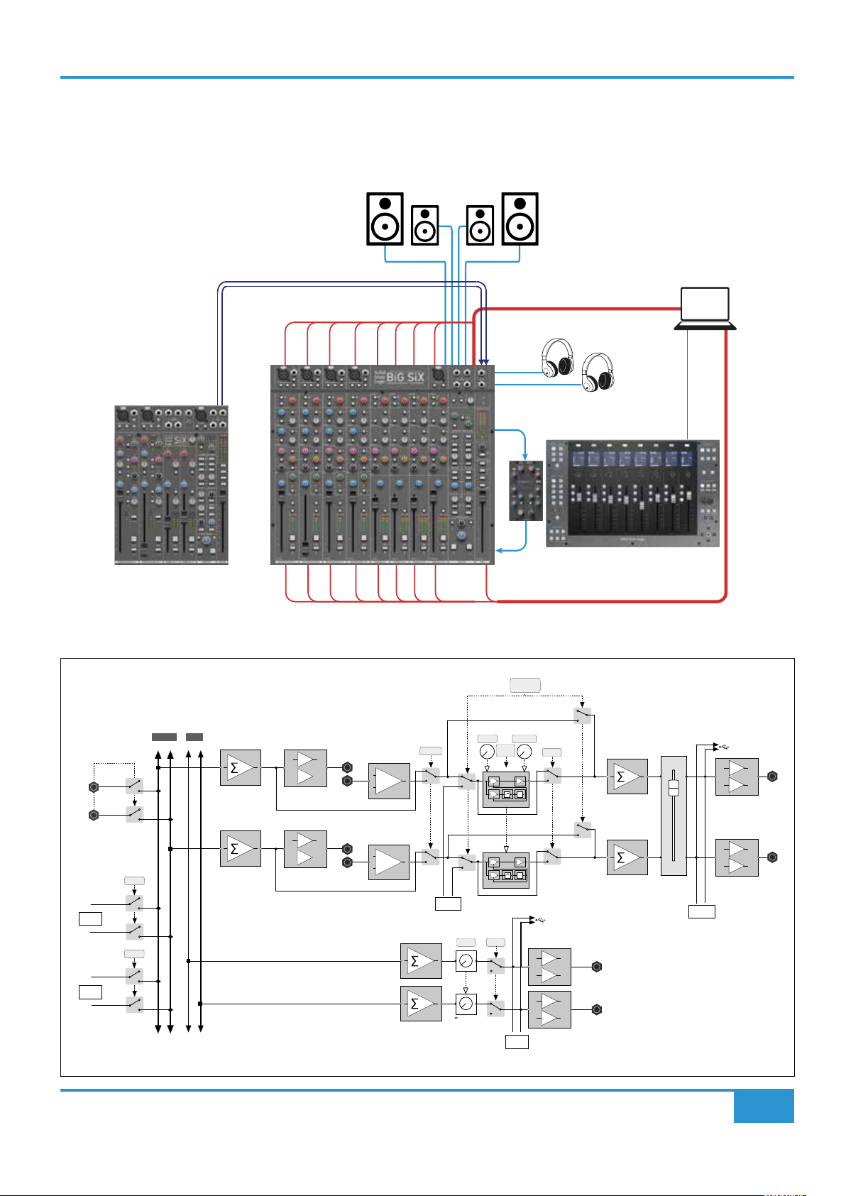
SUM INPUT TO MAIN BUS
The "SUM I/P TO MAIN connections on the rear panel are a simple pair of unity gain, stereo, buffered line input connections that
sum directly onto the Main Left and Right buses. Typically these might be used to cascade the mix bus signals from another sub-
mix console onto the BiG SiX Main bus, such as an SSL SiX console as illustrated below.
MAIN MONITORS
ALTERNATIVE MONITORS
DIGITAL
AUDIO
WORKSTATION
USB
1
USB
6
A
U
D
I
O
I
N
MAIN MIX
OUTPUT
16 AUDIO OUT
G
K
V
o
x
1
BDS
B
A
S
S
D
R
N
U
R
M
S
B
T
E
K
R
Y
G
S
S
V
X
SUM I/P
TO MAIN
SEND
PHONES 1
PHONES 2
MAIN BUS INSERT
MIX
EQ
RETURN
G
K
V
o
x
1
BDS
B
A
S
S
D
R
N
U
R
M
S
B
T
E
K
R
Y
G
S
S
V
X
M
I
X
Main Mix Bus Block Diagram showing 'Sum I/P to Main' connection on left hand side.
BUS COMP to
∑ ST CUE 1
G SERIES BUS COMP
MUTE
MAKE UP
AUTO
RLS
VCA
S/C
VCA
VCA
S/C
VCA
BUS B
TO MON
SUM IP
TO MAIN
FROM
EXT 1
FROM
EXT 2
MAIN
BUS B
MIX AFL
L R
L R
L R
L R
L
R
EXT 1
EXT 2
SEND
+
-
SEND
+
-
RETURN
+
-
RETURN
+
-
INSERT
FROM
ST CUE 1
T/HOLD
LEVEL
to +10dB
DAW CONTROLLER
IN
USB
SEND
13/14
+
-
+
-
BUS B
OUT
USB
SEND
15/16
+
-
L
MAIN
OUT
+
-
MAIN BUS
TO MON
L
R
R
BiG SiX User Guide
17

Console Overview
ST CUE 1 TO G COMP & SUM TO MAIN BUS
This somewhat strangely named switch/feature allows the use of Stereo Cue 1 to create parallel mixes. A typical example is where
you want to use the bus compressor to act on a drum mix and this to then be summed in parallel to the main mix i.e. creating a
compressed drum mix, but with other elements left uncompressed. By creating the parallel drum mix on Stereo Cue 1 from the
console's channels, if you then press ST CUE 1 TO G COMP & SUM TO MAIN BUS the Stereo Cue 1 mix passes through the G
Series Bus Compressor and it is summed with the Main mix, while the Main mix bypasses the G-Series Bus Compressor. e.g.
Normal signal ow:
Main Bus Main InsertChannel OP G Bus Comp Main Fader Main Output
St Cue 1 OP St Cue 1 Output
St Cue 1 Bus
St Cue 1 Master
(+Ext/Talk Sum)
With ST CUE 1 TO G COMP & SUM TO MAIN BUS selected:
St Cue 1 OP
Main Bus Main InsertChannel OP
St Cue 1 Bus
St Cue 1 Master
(+Ext/Talk Sum)
SUM
G Bus Comp
Main Mix Bus Block Diagram
FROM
ST CUE 1
LEVEL
to +10dB
G SERIES BUS COMP
T/HOLD
SUM IP
TO MAIN
FROM
EXT 1
FROM
EXT 2
MAIN
BUS B
MIX AFL
L R
L R
L R
L R
L
R
EXT 1
EXT 2
SEND
+
-
SEND
+
-
RETURN
+
-
RETURN
+
-
INSERT
MUTE
Main Fader Main Output
St Cue 1 Output
BUS COMP to
∑ ST CUE 1
MAKE UP
AUTO
RLS
VCA
VCA
IN
S/C
USB
SEND
15/16
+
-
L
MAIN
OUT
VCA
S/C
VCA
MAIN BUS
BUS B
TO MON
USB
SEND
13/14
+
-
+
-
L
BUS B
OUT
R
+
-
TO MON
R
18
BiG SiX User Guide

Console Overview
G-Series Bus Compressor
The G Series Bus Comp in BiG SiX is a stereo compressor applied across the Main Mix bus, using exactly the same circuit topology
as the original design found on the SL4000 G-Series console released in 1989 (which in-turn was
evolved from the earlier E-Series consoles).
The T/HOLD pot adjusts the Threshold for the compressor, with ve LEDs indicating the amount
of gain reduction applied (-1, -3, -6, -9, -15 dB). The compressor uses the 4:1 ratio, 30 ms attack
and 100 ms release settings from the original processor which are preferred settings for many
SSL large format console users. BiG SiX also features a selectable AUTO RELEASE switch. This
changes the 100 ms release setting and uses the same dual rate Auto Release characteristic as
the original G-Series Bus Compressor, which is another popular setting option from the larger
consoles for some users. The dual release time constant Auto Release circuit automatically increases the release time once the
compression acts over a longer time period. This results in shorter release times after short transient compression and longer
release times from more continuous compression action. Auto Release can result in longer release times depending on signal
content which may appear as if the LED meters are 'stuck on', however this is normal behaviour. Adjustable MAKE UP gain and a
bypass ‘IN’ switch allow level matching and switching for direct comparisons of the clean and processed signals.
The bus compressor side chain also has a 1st order High Pass Filter at approx 50 Hz, a feature of more modern SSL bus
compressor designs to give smoother performance from mixes with prominent bass content.
MAIN
BUS B
MIX AFL
L R
L R
L R
L R
L
SUM IP
TO MAIN
R
EXT 1
FROM
EXT 1
EXT 2
FROM
EXT 2
Main Bus Block Diagram
SEND
+
SEND
+
BUS COMP to
∑ ST CUE 1
G SERIES BUS COMP
RETURN
-
+
-
INSERT
T/HOLD
MAKE UP
AUTO
RLS
VCA
VCA
IN
S/C
USB
SEND
15/16
+
-
L
MAIN
RETURN
-
+
-
FROM
ST CUE 1
LEVEL
to +10dB
VCA
VCA
MUTE
BUS B
TO MON
S/C
MAIN BUS
USB
SEND
13/14
+
-
+
-
L
BUS B
OUT
R
TO MON
OUT
+
-
R
BiG SiX User Guide
19

Console Overview
USB-C Interface
BiG SiX contains a class compliant USB interface to connect to a PC or MAC. The interface is paired with 16 high quality A to D
and D to A converters that are connected to the SuperAnalogue signal chain in BiG SiX.
USB Cables & Power
Please use one of the provided USB cables ('C' to 'C' or 'C' to 'A') to connect BiG SiX to your computer. The connector on the rear
of BiG SiX is a 'C' type. The type of USB port you have available on your computer will determine which of the two included cables
you should use. Newer computers may have 'C' ports, whereas older computers may have 'A'. As this is a USB 2.0 compliant
device, it will make no difference to the performance as to which cable you use.
BiG SiX is powered independently from the computer's USB-bus power. When the unit is locked to USB correctly, the green USB
LED will light a steady green colour. For best stability and performance, we recommend using one of the included USB cables. Long
and low quality USB cables (especially 3 m and above) should be avoided as they tend to suffer from inconsistent performance.
USB Hubs
Wherever possible, it is best to connect BiG SiX directly to a spare USB port on your computer. If you do need to connect via a USB
2.0 compliant hub, then it is recommended that you choose one of high enough quality to provide reliable performance - not all
USB hubs were created equal. With BiG SiX, we optimise the audio performance of a USB interface and as such, some low-cost
self-powered hubs might not always be up to the task. Usefully, you can check out our FAQs at solidstatelogic.com/support to
see which hubs we've succesfully used and found to be reliable with BiG SiX.
Safety Notices
Please read the Important Safety Notices supplied in the BiG SiX packaging before use.
System Requirements
Mac and Windows operating systems and hardware are constantly changing. Please search for 'BiG SiX Compatibility' in our online
FAQs to see if your system is currently supported.
Drivers and Downloads
USB Drivers, Mac and Windows.
Mac
The USB interface in BiG SiX is Core Audio compliant, which
means it should be seen by a Apple's OSx software without the
need for any additional drivers. Core Audio was introduced by
Apple in OSx version 10.3 (Panther), however the BiG SiX USB
interface has only been tested with Apple OSx version 10.14
(Mojave) or later.
Once connected to OSx, the audio driver for BiG SiX should
be visible in the Sound Preferences panel.
20
BiG SiX User Guide

Console Overview
To manage the routing of the Mac System Audio to BiG SiX, this is set-up using the AUDIO DEVICES menu of the AUDIO MIDI
SETUP menu, typically found in the Applications/Utilities Menu of OSx e.g.
Also in this menu is where the Mac's audio routing to the BiG SiX may be set-up, using the
CONFIGURE SPEAKERS menu on this page. For example, you may want to configure the
Mac output to send to EXT 2 on BiG SiX, in which case routing the 'Speakers' to Outputs
15/16 will enable this, shown in this diagram on the right...
By selecting BiG SiX as the audio interface in the DAW, all 16 USB channels will be visible to the DAW. How these are displayed
is controlled by the DAW, for example, in Logic Pro, this is how BiG SiX appears in the PREFERENCES/AUDIO/DEVICES menu...
BiG SiX User Guide
21

Console Overview
The outputs from BiG SiX now appear as discrete sources for the input routing of the DAW again
an example for Logic Pro is shown on the right...
Similarly the inputs to BiG SiX appear as discrete sources for the
output routing of the DAW again an example for Logic Pro is shown
on the right...
It's worth noting that a quirk of Logic Pro is that the 'Stereo Output'
routing is 'attached' to Logic's outputs 1 and 2. This can be changed
in Logic's PREFERENCES/AUDIO/IO ASSIGNMENTS menu, however
changing the default stereo output (for example to 15/16), doesn't
release outputs 1 & 2 to be discretely routed from the DAW paths.
This can be resolved in Logic by creating an Aggregate Device in
OSx. An internet search for "Logic Pro - Changing stereo output
from 1-2" should discover some suggested solutions and further
discussion of the issue.
22
BiG SiX User Guide

Console Overview
Windows
Windows based PCs will need to install the SSL USB Audio ASIO/WDM driver, which can be found in the Support/Downloads
section of the SSL website at www.solidstatelogic.com/. The USB Driver for BiG SiX is also shared with other SSL USB interfaces,
if other SSL USB interfaces are connected then there will be a drop-down selector for the connected SSL USB devices.
After selecting 'Next' the screen changes to ask where the Driver is to be installed. A default location will be automatically chosen,
but this can be over-ridden if required...
Windows Driver Installation
Open the driver installer software.
There should be a screen similar to this...
After selecting 'Next' the screen changes to ask where the
Driver is to be installed.
A default location will be automatically chosen, but this can be
over-ridden if required...
The install process should start and show the activity of the
installer.
BiG SiX User Guide
After a short while the installer should nish with the completion
screen.
The nal install procedure may be a prompt to re-start the
computer or reconnect the device to complete the install
process.
23

Console Overview
USB Interface in Windows
The BiG SiX Windows driver supports both ASIO and standard Windows audio support. The ASIO support will allow the 16
individual audio channels to appear to DAWs as discrete channels. You may need to set up your DAW to both see the SSL ASIO
driver and also have the 16 inputs and outputs appear. For example, here's the Audio Device Preferences panel from Cockos'
Reaper DAW. The Audio System is set to use ASIO driver and see USB inputs 1-16 and outputs 1-16.
For the best and most exible performance with DAW's ASIO is the preferred choice. For other Windows audio formats, the driver
arranges the USB signals to and from BiG SiX in pairs, the output from the PC to BiG SiX are labelled as Output 1/2, Output 3/4,
etc. to Output 15/16. Windows controls the order these pairs appear, so they may not be in sequence!
The inputs to the PC from BiG SiX are similarly labelled Input 1/2, etc. up to Input 11/12, the remaining Inputs are labelled according
to their source, i.e. Input Bus B L/R and Input Main Mix L/R these are USB inputs 13/14 and 15/16 respectively.
24
BiG SiX User Guide

Console Overview
USB Signal Routing and Block Diagram
BiG SiX retains all the SuperAnalogue signal quality attributes of its smaller sister SiX console, however with a larger footprint BiG
SiX also incorporates 16 high quality Analogue to Digital and Digital To Analogue converters and a class compliant USB interface.
This interface is capable of interfacing all 16 digital channels of digital audio to and from a connected workstation at sample
frequencies of 44.1, 48, 88.2 and 96 kHz with 24 bit resolution.
The block diagram opposite shows how the A to D and D to A circuits are connected within BiG SiX.
USB Returns 1 - 16 (Signal ow from the DAW to BiG SiX)
USB returns 1 to 4 from the workstation are connected to a switched input to the four Mono SuperAnalogue channels. They are
connected after the pre-amp and therefore are at unity gain (0 dB) into the mono channel signal path.
USB returns 5 to 12 are connected to a switched input to the four stereo channels. They are connected prior to the line amplifier
and therefore are at unity (0 dB) in the centre detent position of the Trim control with +20 to -10 dB of gain available.
USB returns 13/14 and 15/16 are connected to the External Inputs by way of a pair of switches
located next to the TALK LEVEL control. These switches override the TRS External Input
connections at the top of the front panel. There are also small USB labels next to the EXT 1 and
EXT 2 switches to act as reminders.
USB Sends 1 - 16 (Signal ow to the DAW from BiG SiX)
USB sends 1 to 4 to the workstation are connected to the pre-fader output of the four Mono SuperAnalogue channels. This feed
can be switched Post Fader by selecting the individual USB OUT POST FADER switches next to each of the 100 mm faders for the
channel. This is useful if you want to record the channel signal including its level back to the DAW. Typically this is used where a
summing mix of stems is recorded back to the workstation, so that to re-create the mix at a later date, the stems are simply returned
to the console with the channel at unity gain, re-creating the original summing mix for re-mixing/re-balancing.
USB sends 5 to 12 are similarly** connected to the pre-fader output of the four stereo channels. Again, this feed can be switched
Post Fader by selecting the individual USB OUT POST FADER switches next to each of the 100 mm faders for the channel. These
Post Fader feeds are also post the Balance control to make it easy to return a stereo stem mix at unity gain for later re-mixing.
** USB Sends 9/10 and 11/12 can be re-directed to be fed from Stereo Cue 1 and Stereo Cue 2
respectively using a pair of switches at the top of the Stereo Cue Master section. If either switch
is pressed, the green LED will light. This feature is useful if you want to use the Stereo Cue Sends
to feed effects processing created in the workstation. The effects return would typically be fed to the External Inputs and summed
to the Main Bus using the EXT 1 and/or EXT 2 switches above the Main Fader.
USB Sends 13/14 are connected to the output of Bus B, after the Bus B MUTE and stereo Level Control.
USB Sends 15/16 are connected to the output of the Main Bus after the Main Fader, providing a simple way to print a mix back to
the workstation.
BiG SiX User Guide
25

Console Overview
USB
Send 1-16
USB
Rtn 1-16
Input
Ext 2
USB 13/14 USB 15/16
Input
Ext 1
Stereo
In 11/12
From
EXT 2
EXT 1
USB 11/12
From
USB 15/16
From
USB 13/14
Cue 1 to
USB 9/10
Line
Amp
Cue 2 to
USB 11/12
St Cue 1
Out
St Cue 1 Bus
St
Cue 1StCue 2
St Cue 2
Out
St Cue 2 Bus
USB 15/16
USB 13/14
Bus B Output
Main Bus Output
USB Out
Post Fader
St
EQ
BUS B
USB 9/10 USB 11/12
Key
From
In 9/10
In (x 2)
USB 9/10
From
USB 5/6
Pre
(7/8)
Amp
Line
Line
Amp
Amp
From
USB 1
St
St
(2,3,4)
St
Cue 1StCue 2
Cue 1StCue 2
Cue 1StCue 2
St
St
EQ
EQ
EQ
Dyn
Insert
FaderFader Fader
Fader
USB Out
Post Fader
USB Out
Post Fader
USB Out
Post Fader
BUS B
BUS B BUS B
Bus B
USB 5/6
(7/8)
USB 1
(2,3,4)
Main Bus
USB 9/10 USB 11/12
Stereo
USB 5/6
(7/8)
Stereo
USB Return From DAW
USB Send To DAW
USB 1
(2,3,4)
In (x 4)
Channel
SuperAnalogue
26
BiG SiX User Guide
DIGITAL
AUDIO
WORKSTATION
Application Examples
USB
16 AUDIO OUT
16 AUDIO IN
PHONES 2
(STEREO CUE 2)
MAIN MONITORS
ALTERNATIVE MONITORS
TALK
BACK
MIC
PHONES 1
S
T
E
C
1
U
S
B
U
EXT 1
EXT 2
STEREO 11/12
STEREO 5/6
STEREO 7/8
STEREO 9/10
BiG SiX User Guide
DI 2
DI 1
MIC 2
MIC 1
27

Application Examples
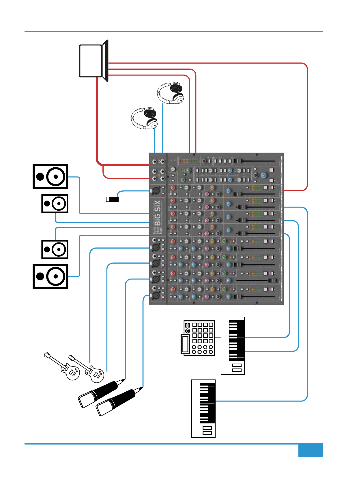
Application Examples - Desktop Studio
Opposite is a simple application of BiG SiX in a typical desktop studio application.
The mics for the vocals and guitars are connected to the SuperAnalogue XLR microphone inputs then processed with the SSL
Channel Compression and EQ. The headphone 2 output is used to feed the artists with the Phones source being Stereo Cue 2.
Sequenced drum machines and keyboards are connected to the Stereo Line Input channels 5-10.
Stereo Cue Send 1 is being routed to USB sends 9-10 and hence to the DAW, where they are being fed to reverb effects. The
effects outputs are being returned via USB 13-14 to EXT 1 summed to the Main Mix (or into the Monitor Source, if the main mix is
to be recorded dry).
The mics are recorded to the Digital Audio Workstation (DAW) from the Main mix bus, using the Stereo Bus Compressor to smoothly
manage the combined transients.
DAW playback is sent into Stereo Channel 11/12, which is routed to Bus B, and then to the artists using the Stereo Cue 2 control.
If useful, two separate DAW feeds can be used into two Stereo Channels allowing for separate click-track and playback level
controls to the artist's cue feed.
The talkback system keeps the producer in touch with the artist using a phantom powered condenser Mic and the Listen Mic
Compressor and TALK level control conveniently manage the talkback levels.
The Studio has two sets of monitors connected to the Main and Alternate monitor outputs, the monitor controls allow listening on
large and small monitors and at different levels using the Dim switch and level control, the Mono selection allows simple mono
compatibility check, for example to check if any 'wide' signals are disappearing in a mono listening environment, e.g. when listening
on a single small speaker.
28
BiG SiX User Guide
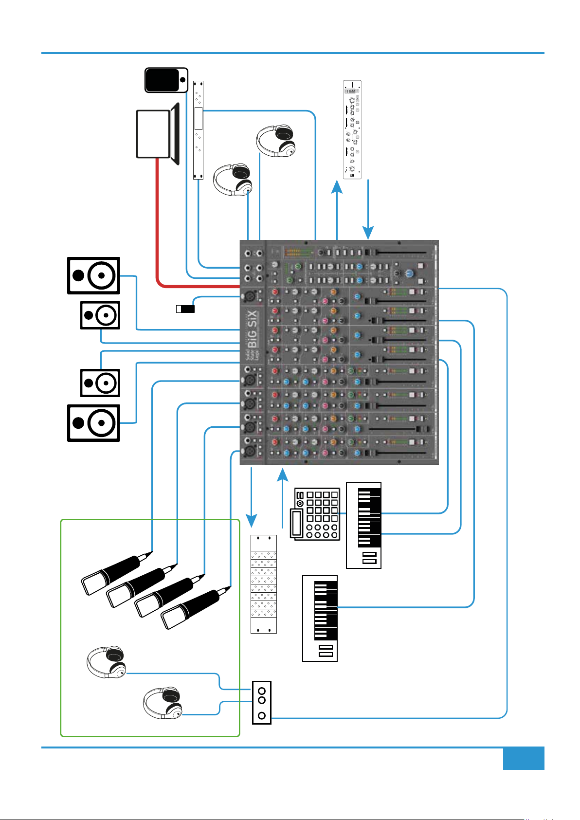
IN
IN
IN
IN
IN
INSERT
PRE EQ
BYPASS
DIGITAL
AUDIO
WORKSTATION
16 AUDIO IN
TALK
USB
16 AUDIO OUT
U
BACK
S
MIC
Application Examples
FUSION
FUSION
STEREO ANALOGUE COLOUR
STEREO ANALOGUE COLOUR
96404
6
2421181512
121518
21
[POST I/P TRIM]
[POST I/P TRIM]
+8
+8
+4
+4
+12
+12
0
0
dB
dB
[M/S MODE]
[M/S MODE]
–12
–12
OUTPUT TRIM
OUTPUT TRIM
–4
–4
–8
–8
+6–6
+6–6
0
0
dB
dB
WIDTH
WIDTH
–2 +2
–2 +2
–4 +4
–4 +4
+12–12
+12–12
STEREO IMAGE
STEREO IMAGE
0
0
dB
dB
SPACE
SPACE
–4 +4
–4 +4
–8 +8
–8 +8
10
10
203
203
kHz
kHz
57
57
X-OVER
X-OVER
4
4
–6
–6
–10
–10
–2
–2
HF COMPRESSOR
HF COMPRESSOR
dB
dB
+2
+2
+10
+10
THRESHOLD
THRESHOLD
+6
+6
+9–9
+9–9
0
0
20
20
dB
dB
HIGH
HIGH
16
16
–3 +3
–3 +3
kHz
kHz
–6 +6
–6 +6
12
12
8
8
90
90
VIOLET EQ
VIOLET EQ
70
70
Hz
Hz
50
50
+9–9
+9–9
30
30
0
0
dB
dB
LOW
LOW
–3 +3
–3 +3
–6 +6
–6 +6
8
8
MAXMIN
MAXMIN
6
6
4
4
DENSITY
DENSITY
2
2
9
9
111
111
7
7
VINTAGE DRIVE
VINTAGE DRIVE
MIX PROCESSING
DRIVE
DRIVE
5
5
3
3
50
50
40
40
Hz
Hz
HPF
HPF
30
30
OFF
OFF
+8
SEND
+4
+12
0
dB
O/L
O/L
INPUT TRIM
–12
–4
–8
INSERT
MAIN BUS
RETURN
FX
PHONES 2
EXT 2
EXT 1
PHONES 1
ST CUE 2
B
MAIN MONITORS
ALTERNATIVE MONITORS
MIC 4
MIC 3
MIC 2
MIC 1
SEND
INSERTS
CHANNEL
RETURN
RACK EQ & DYN PROCESSING
STEREO 5/6
STEREO 7/8
STEREO 9/10
ST CUE 1
HP AMP
ISO BOOTH
BiG SiX User Guide
29

Application Examples
Application Examples - Small Project Studio, Record/Overdub
Opposite is a simple application of BiG SiX in a typical small project studio application. A key difference in this example is that
the artists are in an isolation booth and the two console headphone outputs are being used by a separate engineer and producer
each with their own level control.
The microphones are connected to the SuperAnalogue XLR microphone inputs, the SuperAnalogue Channel Insert points are being
used to send the amplified mic signals to external 500 series rack mounted EQ and Dynamics processor for precise control over
signal levels and shaping. The Stereo Cue 1 output is used to feed the artists headphones via a dedicated headphone amplifier.
Sequenced drum machines and keyboards are connected to the Stereo Line Input channels 5-10.
Stereo Cue Send 2 is being used to feed an external rack effects processor. The processor output is being returned via EXT 2 and
summed to the Main Mix and into Stereo Cue Send 1 to feed the artist foldback (or into the Monitor Source, if the main mix is to
be recorded dry).
A phone/tablet is connected to EXT 1 to allow a rough idea of the musical piece to be played in to the studio and also, via Stereo
Cue Send 1, to the artists.
The mics are recorded to the Digital Audio Workstation (DAW) directly from USB Sends 1-4 from the channels, pre-fader, or from
the Main mix bus as a submix, using the Stereo Bus Compressor to smoothly manage the combined transients.
DAW playback is sent into Stereo Channel 11/12, which is routed to Bus B, and then to the artists using the Stereo Cue 2 control.
If useful, two separate DAW feeds can be used into two Stereo Channels allowing for separate click-track and playback level
controls to the artist's cue feed.
The talkback system keeps the producer in touch with the artist using a phantom powered condenser Mic and the Listen Mic
Compressor and TALK level control conveniently manage the talkback levels.
The Studio has two sets of monitors connected to the Main and Alternate monitor outputs, the monitor controls allow listening on
large and small monitors and at different levels using the Dim switch and level control, the Mono selection allows simple mono
compatibility check, for example to check if any 'wide' signals are disappearing in a mono listening environment, e.g. when listening
on a single small speaker.
30
BiG SiX User Guide

Application Examples
DIGITAL
AUDIO
WORKSTATION
USB
16 AUDIO OUT
1
USB
6
A
U
I
D
O
PHONES 1
I
N
PHONES 2
SEND
DAW CONTROLLER
EQ
MIX
MAIN BUS INSERT
RETURN
I
M
X
MAIN MONITORS
ALTERNATIVE MONITORS
BiG SiX User Guide
K
B
V
X
G
S
E
Y
K
S
T
R
G
S
R
U
D
M
S
R
N
B
D
S
S
B
A
x
o
V
1
K
B
V
X
G
S
E
Y
K
S
T
R
G
S
R
U
D
M
S
R
N
B
D
S
S
B
A
x
o
V
1
31

Application Examples
Application Examples - Small Project Studio - Hybrid SuperAnalogue Mixdown
In this example, BiG SiX is being used as part of a hybrid mixdown setup.
Individual signals and stereo stems are being fed to BiG SiX via USB from the DAW, with separate stem mixes for the various
components of the mix. The detailed balance of the stems is controlled using the external DAW controller (in this case SSL's UF8).
The stems are mixed/summed in BiG SiX over USB and the mix balanced using the faders, pan controls and SuperAnalogue
processing. The overall mix is compressed using the Bus Compressor with a stereo EQ placed in the Main Bus Insert.
The output of the channel paths of BiG SiX are being recorded back to additional tracks the DAW using the Post Fader USB output,
allowing the balanced stem tracks to be printed to separate tracks on the DAW. This enables simple re-balancing at a later date by
sending the stem tracks back to BiG SiX with its paths and faders at unity gain. The Main Mix is also being sent back to the DAW
to print the main mix alongside the stems.
32
BiG SiX User Guide

DIGITAL
AUDIO
WORKSTATION
Application Examples
USB
CONNECTIONS
ANALOGUE
CONNECTIONS
KEY
MAIN MONITORS
ALTERNATIVE MONITORS
MIC 4
TALK
PHONES 2
PHONES 1
FX STEM to ST 7/8
MUSIC STEM to ST 9/10
DIALOGUE FX/REVERB RETURN to ST 5/6
MIC
BACK
MIC 3
MIC 2
MIC 1
DIALOGUE MIX
ST CUE 2 SEND TO DIALOGUE FX/REVERB
ST CUE 1
/
V
O
/
V
O
/
V
O
/
V
O
4
M
3
M
2
M
1
M
BiG SiX User Guide
HP AMP
VOICE BOOTH
33

Application Examples
Application Examples - Post Production - ADR or Foreign Language Dubbing
In this example, BiG SiX is being used as the hub of a multi-mic ADR or foreign language dubbing suite.
The key elements are low latency headphone feeds for the actors, Talkback from the studio to the VO booth and separate record
feeds and cue send for both artist headphone mix and dialogue reverb.
The guide Effects (FX) and Music stems are being fed via USB from the DAW to Stereo Channels 7/8 and 9/10 respectively. These
are then sent to Cue 1 to feed the actors' headphone mix using the Stereo Cue 1 output to feed a Headphone distribution amplifier.
The Actors' microphone(s) are being fed into SuperAnalogue Channels 1 to 4, and the outputs of these record channels are being
fed independently to the DAW for recording via USB outputs 1-4.
Dialogue reverb effects created in the DAW are fed from Stereo Cue 2 mixes from SuperAnalogue Channels 1-4, using the Cue 2
Output to USB 11/12 Send feature. The output of these reverb effects from the DAW are then fed back to BiG SiX on USB to Stereo
Channels 5/6 where they are sent to the actor's headphone mixes on Stereo Cue 1. The dialogue reverb could either be recorded
directly within the DAW, or could be fed from the console back to the DAW on the USB output to the DAW from Stereo Channels
5/6. This may be useful if, as part of managing the dialogue reverb, the use of the console fader to manage the reverb balance
was useful.
The stereo dialogue sub-mix is being recorded from the Main bus, via USB outputs 15/16. If desired, the reverb mix could be
separated from the dry dialogue sub-mix by sending the reverb mix to Bus B on Stereo Channels 5/6 and then recording the Bus
B output via USB outputs 13/14.
34
BiG SiX User Guide

Application Examples
MAIN MONITORS
ALTERNATIVE MONITORS
DIGITAL
AUDIO
TALK
BACK
WORKSTATION
USB
MIC
REMOTE
PLAYBACK
USB
REMOTE SOURCES
PHONES 2
PHONES 1
ST CUE 2
S
E
T
R
S
A
B
U
M
ST CUE 1
STEREO 5/6
LOCAL SOURCES
BiG SiX User Guide
MIC 4
FX REPLAY
MIC 3
MIC 2
MIC 1
HP AMP
35

Application Examples
Application Examples - Podcast Studio
BiG SiX is a powerful choice for professional online content creation.
It’s ideal for vloggers, producers and podcasters who need to achieve high fidelity audio recordings quickly and intuitively.
Here, BiG SiX acts as the nerve centre, with local sources including, four mic inputs connected to BiG SiX’s high quality
SuperAnalogue mic pre’s, with SSL Compression and EQ, local playback connected to one of the Stereo Channels and remote
playback feeds connected to the second stereo channel. Additional stereo sources can be incorporated via External Inputs 1 & 2.
There are separate local headphone and monitor mixes and a separate cue mix can be created for remote contributors.
The main mix is enhanced by the stereo Bus Compressor for an upload-ready record feed.
36
BiG SiX User Guide

Troubleshooting & FAQs
Troubleshooting & FAQs
Frequently Asked Questions and additional support contacts can be found on the Solid State Logic Website at:
https://www.solidstatelogic.com/support/
Troubleshooting Tips
My BiG SiX is warm to the touch
BiG SiX’s SuperAnalogue audio circuits are designed to run warm and BiG SiX contains a lot of electronics in a small space.
BiG SiX is designed to cool front to back, so ensuring ventilation inlets and outlets (front and rear) have clearance is important to
reliable operation.
There is no output from the monitors
Check that there is something selected in the monitor source section of the console (see page 13). A monitor source needs to be
selected (typically MAIN) to hear something from the monitor outputs. Also check that the ALT button isn't pressed with nothing
connected to the Alternate Monitor connections.
When I connect only to a Left Input, there is also a signal on the Right
This is a feature of the stereo inputs of BiG SiX (see page 11). If an input is only connected to the left input of the stereo input pair
(i.e. Stereo Channel inputs and External Inputs) then the signal is automatically sent to both left and right paths.
There is no signal from the B-Bus output
Check that the the B-Bus Mute button is not pressed. This can be found under the B-Bus output level control which is to the left of
the Main Fader. This button is a simple way to turn the Mute/B-Bus switches on the channel strips into permanant Mute buttons or
simply mute the B-Bus Output if it is being used as a secondary bus output.
There is no signal from the SuperAnalogue Channels
Check the Channel Insert button. If this is ON with no Insert Return connected to the TRS connector then the channel signal will
be muted. The Insert Send is always present and only the Insert Return is switched.
There is no signal to the Main Bus
Check the Main Fader Insert button. If this is ON with no Insert Return connected to the D-Type connectors then the Main Fader
signal will be muted. The Insert Send is always present and only the Insert Return is switched.
BiG SiX User Guide
37

Troubleshooting & FAQs
Warranty
Warranty claims will only be accepted if the purchased product has been used for its intended purpose. Any purchased product
used for an unintended purpose will not be eligible for warranty protection. For all warranty inquiries or claims please address your
claim to the dealer that you purchased the product from or to Solid State Logic if the purchase was directly from Solid State Logic.
Claims must be submitted within a period of two months from the date on which you detected its lack of conformity with the terms
of the warranty. Please include your original proof of purchase when initiating the claim.
➤ Within the EU: Pursuant to the Solid State Logic Terms and Conditions under European consumer law the purchaser has full
statutory warranty rights for two years from the date of purchase of the product. The warranty is valid only in those Member
States of the European Union (EU) who have adopted the applicable EU law into their national legislation. The applicable
national legislation governing the sale of consumer goods is not affected by this warranty.
➤ Outside of the EU: Outside of the European Union a 12 month warranty from date of purchase is applicable.
All returns
➤ No unit will be accepted for repair by Solid State Logic unless accompanied by a valid RMA (Return Material Authorisation)
number, obtainable from Solid State Logic prior to shipping.
➤ All units should be shipped to Solid State Logic in suitable rigid packaging – Solid State Logic cannot be held responsible
for any damage caused by shipping units in other packaging.
38
BiG SiX User Guide
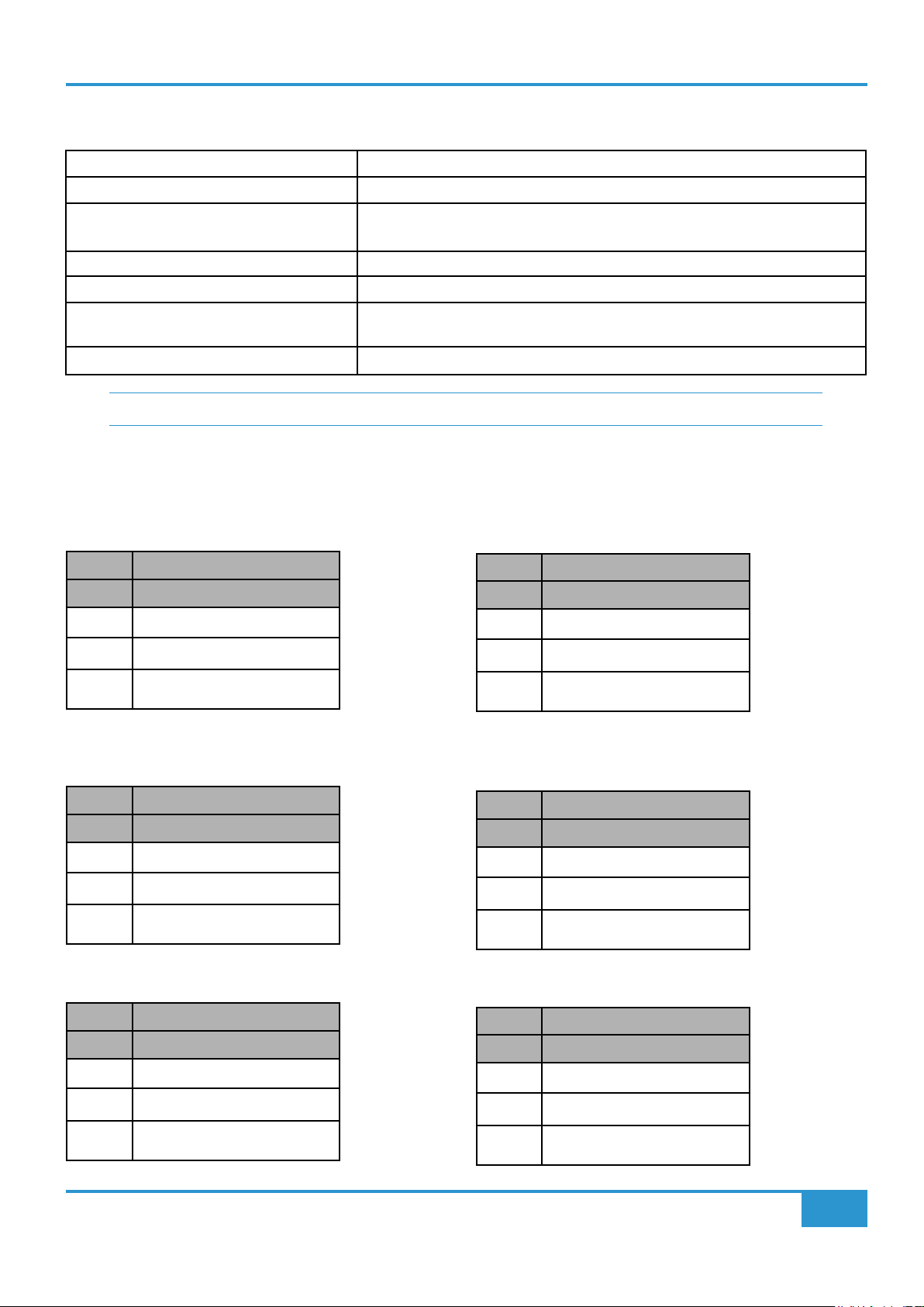
Appendix A - Physical Specication
Front to Back Depth 390.2 mm / 15.4"
Height (from table top inc. feet) 141.2 mm / 5.6"
Width 437.2 mm / 17.2" (Excluding Trim)
489.4 mm / 19.3" (Including Trim)
Power 70 Watts
Unboxed Weight 6.8 kg / 15.0 lbs (Console excluding PSU)
Boxed Size Width x Height x Depth
600 mm x 260 mm x 540 mm (23.6" x 10.2" x 21.3")
Boxed Weight 10.1 kg / 22 lbs
Note: All physical specication values are approximate.
Connector Details
Appendix A
Mono Channels
Microphone Inputs
3-pin XLR Male
Pin Description
1 0 V Chassis
2 Signal +ve (Hot)
3 Signal -ve (Cold)
Stereo Channels
Stereo Channel Line Inputs
1/4" TRS Jack Socket
Pin Description
Tip Signal +ve (Hot)
Ring Signal -ve (Cold)
Sleeve 0 V Chassis
Line Inputs
1/4" TRS Jack Socket
Pin Description
Tip Signal +ve (Hot)
Ring Signal -ve (Cold)
Sleeve 0 V Chassis
External Inputs
Stereo External Line Inputs
1/4" TRS Jack Socket
Pin Description
Tip Signal +ve (Hot)
Ring Signal -ve (Cold)
Sleeve 0 V Chassis
Talkback Microphone Input
3-pin XLR Female
Pin Description
1 0 V Chassis
2 Signal +ve (Hot)
3 Signal -ve (Cold)
BiG SiX User Guide
Foldback/Stereo Cue Outputs
1/4" TRS Jack Socket
Pin Description
Tip Signal +ve (Hot)
Ring Signal -ve (Cold)
Sleeve 0 V Chassis
39

Appendix A
Main Bus Outputs
1/4" TRS Jack Socket
Pin Description
Tip Signal +ve (Hot)
Ring Signal -ve (Cold)
Sleeve 0 V Chassis
Main Monitor Outputs
1/4" TRS Jack Socket
Pin Description
Tip Signal +ve (Hot)
Ring Signal -ve (Cold)
Sleeve 0 V Chassis
Insert Sends/Returns
Bus B Outputs
1/4" TRS Jack Socket
Pin Description
Tip Signal +ve (Hot)
Ring Signal -ve (Cold)
Sleeve 0 V Chassis
Alternate Monitor Outputs
1/4" TRS Jack Socket
Pin Description
Tip Signal +ve (Hot)
Ring Signal -ve (Cold)
Sleeve 0 V Chassis
1/4" TRS Jack Socket
Pin Description
Tip Signal +ve (Hot)
Ring Signal -ve (Cold)
Sleeve 0 V Chassis
DC Power Inlet
4-pin DIN Male
Pin Description
1,4 +15 V, 3.3 A
2,3 0 V Common
Shell Chassis
40
BiG SiX User Guide

Appendix B
Appendix B - Performance Specication
Audio Performance
Default test conditions (unless otherwise stated):
- Source impedance of Test Set: 40 Ω
- Input impedance of Test Set: 200 kΩ
- Reference frequency: 1 kHz
- Reference level: 0 dBu where 0 dBu = 0.775 V into any load
- All unweighted measurements are specied as 22 Hz to 22 kHz band limited RMS and are expressed in units of dBu
- The onset of clipping (for headroom measurements) should be taken as 1% THD
- All distortion measurements are specied with a 36 dB/Octave low pass lter at 20 kHz and are expressed as a percentage
- All levels are intended balanced
Unless otherwise quoted all gures have a tolerance of ±0.5 dB or 5 %.
SuperAnalogue Channel Microphone Amplier
Measurement Conditions Value
Gain **dependent on potentiometer tolerances Variable from +6 dB to +72 dB**
Input Impedance 1.2 kΩ
Max Input Level 1% THD 21 dBu
Output Headroom >+27 dBu at onset of clipping
Frequency Response - 20 Hz to 20 kHz
- -3 dB high rolloff
THD+Noise (-20 dBu applied, +30 dB gain) @ 1 kHz (lter 22 Hz to 22
kHz)
CMRR (-10 dBu applied, +30 dB gain) @100 Hz - > 90 dB
Equivelent Input Noise (EIN) 150 Ω termination, maximum gain - <-127.5 dBu
- +0.0/-0.2 dB
- > 80 kHz
- < 0.0015 %
- typically -129 dBu
SuperAnalogue Channel Line Input Amplier
Measurement Conditions Value
Gain **dependent on potentiometer tolerances Variable from -3 dB to +63 dB**
Input Impedance 10 kΩ
Hi-Z Input Impedance 1 MΩ
Max Input Level 1% THD >+27 dBu before clipping
Output Headroom >+27 dBu at onset of clipping
Frequency Response - 20 Hz to 20 kHz
- -3 dB high rolloff
THD+Noise (-20 dBu applied, +30 dB gain) @ 1kHz (lter 22 Hz to 22
kHz)
CMRR (-10 dBu applied, +30 dB gain) @100 Hz > 80 dB
Equivelent Input Noise (EIN) 150 Ω termination, maximum gain <-120 dBu
+0.0/-0.2 dB
> 80 kHz
< 0.0015 %
BiG SiX User Guide
41
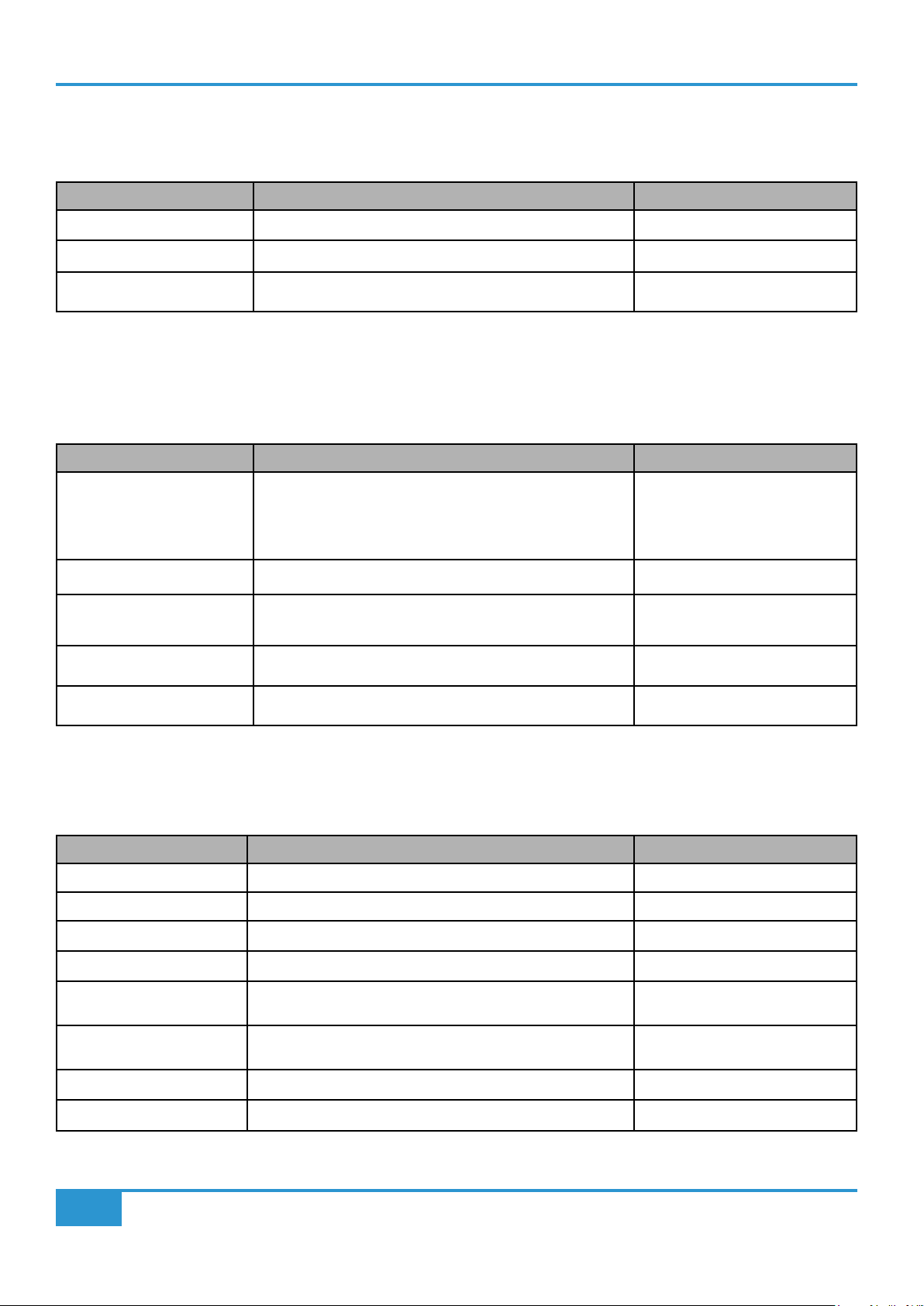
Appendix B
Channel Equaliser
Signal applied to line input and measured at the channel insert send. EQ switched in with EQ controls centred in shelf mode.
Measurement Conditions Value
Output Headroom >+27 dBu at onset of clipping
THD+Noise +20 dBu @ 1 kHz (lter 22 Hz to 22 kHz) < 0.0015 %
Noise <-87.5 dBu
Channel Compressor
Signal applied to line Input and measured at the channel insert send. Compressor switched into channel path with the compressor’s
threshold set to +10 dB.
Measurement Conditions Value
Ratio (slope)
Threshold
Attack Time
Release Time
Output Headroom >+26 dBu at onset of clipping
THD+Noise +10 dBu @ 1 kHz (lter 22 Hz to 22 kHz)
+20 dBu @ 1 kHz (lter 22 Hz to 22 kHz) Threshold @-20
Frequency Response - 20 Hz to 20 kHz +0.2/-0.4 dB
Noise <-87.5 dBu
2:1
+10 to -20 dB (typical)
5 ms
300 ms
< 0.07 %
< 0.7 % (typical)
SuperAnalogue Stereo Channel Line Input Amplier
Signal applied to stereo channel line input and measured at main output insert send with the stereo channel’s input gain trim and
balance controls in their indent position with the stereo channel’s fader adjusted for unity gain.
Measurement Conditions Value
Gain Variable from -10 dB to +20 dB
Input Impedance 10 kΩ
Max Input Level 1 % THD >+27.5 dBu before clipping
Output Headroom >+27 dBu at onset of clipping
Frequency Response - 20 Hz to 20 kHz
- -3 dB high rolloff
THD+Noise (-20 dBu applied, +30 dB gain) @ 1 kHz (lter 22 Hz to 22
kHz)
CMRR >55 dB
Equivelant Input Noise (EIN) 150 Ω termination, maximum gain <-93 dBu
42
+0.0/-0.2 dB
> 100 kHz
< 0.001 %
BiG SiX User Guide
Appendix B
Overall Channel Signal Chain Specications
Signal applied to Line Input of a mono channel, and routed to specied output by shortest path. All controls set at, out or at unity
gain as appropriate. Pan set to full left or right.
Measurement Conditions Value
Foldback, B-Bus & Main Output
Output Headroom into 600 Ω at onset of clipping
into 10 kΩ at onset of clipping
THD+Noise +20 dBu @ 1 kHz (lter 22 Hz to 22 kHz) < 0.0015 %
Frequency Response 20 Hz to 20 kHz
-3 dB high rolloff
Output Impedance 100 Ω
Pot centre detent accuracy: +/-1 dB, typically <0.5 dB
>24 dBu
>27.5 dBu
+0.0/-0.2 dB
>80 kHz
Overall Console Noise
Measured at main outputs, channels routed as required with pans / balance controls centred, using Line input with termination. All
controls set at, out or at unity gain as appropriate, channel and master faders calibrated for 0dB.
Measurement Conditions Value
Noise at Main Output 1 mono channel routed (all other muted)
All channels routed
<-90 dBu
(<–116 dB with respect to +26 dBu)
< –82.5 dBu
(<–108.5 dB with respect to +26 dBu)
ADC and DAC Converter
Measurements taken at 48 kHz
Measurement Conditions Value
Alignment Level 0 dBFS +24 dBu
THD+Noise DAC -10 dBFS @ 1 kHz (lter 22 Hz to 22 kHz)
ADC -4 dBFS @ 1 kHz (lter 22 Hz to 22 kHz)
Dynamic Range DAC A-weighted
ADC A-weighted
0.001 %
0.0007 %
117 dB
117 dB
Environmental Requirements
Temperature range:
Operating: +1 to 30 degrees Celsius.
Storage: -20 to 50 degrees Celsius.
BiG SiX User Guide
43

Appendix C
Appendix C - BiG SiX Block Diagram
USB
POST
FADER
USB
SUPER ANALOGUE IN (1 of 4)
48V
MIC
+48V
HI-Z
LINE
USB
RETURN
1..4
10K
GAIN
LINE
1.2K
+dB
+6 to +72dB
[-3 to +63dB]
-9dB
1M
T/HOLD
LF
MF
HF
BELL
BELL
USB
HPF
Ø
75 Hz
ST CUE 1
POST
LEVEL
PAN
to 0dB
ST CUE 2
POST
LEVEL
to 0dB
COMP
IN
EQ IN
ON
PAN
PFL
PFL
SEND
+
-
ST CUE 2
MIX
ST CUE 1
L R
L R
L R L R
ST CUE 1
ON
ST CUE 2
PFL
L R
INSERT
RETURN
+
-
SEND
MAIN
BUS B
MIX AFL
1..4
L R
L R
L R
L R
MAIN
BUS B
PAN
L
SUM IP
TO MAIN
R
MAIN
BUS B
EXT 1
EXT 2
SEND
+
-
SEND
+
-
RETURN
+
-
RETURN
+
-
INSERT
LEVEL
to +10dB
BUS COMP to
∑ ST CUE 1
G SERIES BUS COMP
T/HOLD
MAKE UP
AUTO
RLS
VCA
VCA
VCA
VCA
MUTE
IN
S/C
S/C
USB
SEND
13/14
+
L
-
BUS B
+
R
-
USB
SEND
15/16
+
L
-
MAIN
OUT
+
R
-
STEREO IN (1 of 4)
STEREO IN
5..11
USB
RETURN
5..11
STEREO IN
6..12
USB
RETURN
6..12
SSL BiG SiX
Drawn: NF
Revison: 14
Date: 8.12.2020
TRIM
INPUT
USB
+
dB
-
L
R
+
dB
-
-10 to + 20dB
ALT
Headphone Jack 1
Headphone Jack 2
ALT MON
R
MAIN MON
R
L
L
MON SOURCE
MIX
L R
L R
MON
MAIN
L R
PFL
BUS B
PFL
USB
POST
FADER
USB
SEND
5,7,9,11
USB
SEND
LF
MF
HF
MONO
EQ IN
6,8,10,12
BALANCE
+
+
USB RTN
13/14
LEVEL
TO EXT 1
L
+
-
USB RTN
13
EXT 1
+
ST CUE 1
POST
ON
LEVEL
to 0dB
ST CUE 2
POST
ON
LEVEL
to 0dB
PFL
PFL
R
USB RTN
14
L
USB RTN
15
EXT 2
R
USB RTN
16
USB RTN
15/16
TO EXT 2
TALK INPUT
-
+
-
+
-
EXT IN
48V
+48V
to +20dB
LEVEL
to +20dB
+
+45dB
-
EXT 1
EXT 2
LMC
IN
+20dB
MIX
L R
L R
EXT 1
CUE 1
L R
ST CUE 1
LEVEL
EXT 2
to +10dB
TALK
TB
LEVEL
to 0dB
CUE 1 TO 9/10
EXT 1
EXT 2
TALK
3dB
CUE TO USB
+
-
+
-
MIX
L R
L R
CUE 2
L R
MONO
USB
SEND
9
USB
SEND
10
STEREO
CUE 1 OUT
MONITOR
DIM
LEVEL
-3 to -30dB
1L
1R
ST CUE 2
LEVEL
to +10dB
CUE OUTPUTS
CUT
MONITOR
LEVEL
+
-
+
-
to 0dB
ST CUE 2ST CUE 1
PHONES 1
LEVEL
to 0dB
ST CUE 2ST CUE 1
PHONES 2
LEVEL
to 0dB
CUE TO USB
CUE 2 TO 11/12
USB
SEND
11
USB
SEND
12
+
2L
-
STEREO
CUE 2 OUT
+
2R
-
44
BiG SiX User Guide
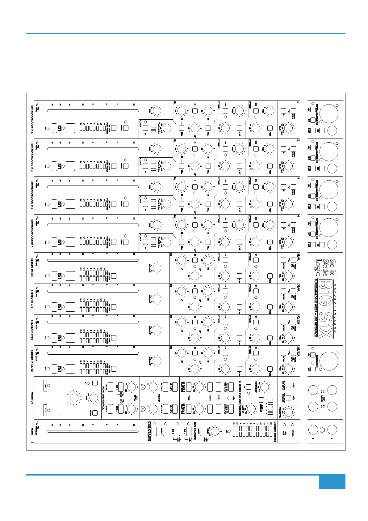
Appendix D - Recall Sheet
This image should scale if you print this page at larger sizes, e.g. A3
Appendix D
SUPERANALOGUE IN 1
TO
USB 1
SUPERANALOGUE IN 2 SUPERANALOGUE IN 3 SUPERANALOGUE IN 4
TO
USB 2
TO
USB 3
TO
USB 4
STEREO IN 5/6 STEREO IN 7/8 STEREO IN 9/10 STEREO IN 11/12
TO
USB 5/6
TO
USB 7/8
TO
USB 9/10
TO
USB 11/12
MONITOR
TO
USB 15/16
MAIN
PAN
RL
PAN
RL
PAN
RL
PAN
RL
21
POST
POST
POST
POST
POST
POST
POST
POST
G-SERIES BUS COMPRESSOR
IN
MAKE UP
15
94069
ST CUE 1
dB
ST CUE 1
dB
ST CUE 1
dB
ST CUE 1 ST CUE 1
dB
ON
PAN
RL
0
0
0
0
POST POST POST POST
ON
PAN
RL
ON
PAN
RL
ON ON
PAN
RL
1 2 3 4
48V HPF [LINE] [LINE] [LINE] [LINE]
FROM
0
USB 1
/
[-3] [+63]
GAIN
dB
+72+6
FROM
0
USB 2
/
[-3] [+63]
GAIN
dB
+72+6
0
USB 3
FROM
/
[-3] [+63]
GAIN
dB
+72+6
0
USB 4
FROM
/
[-3] [+63]
GAIN
dB
+72+6
HI-Z
SUPERANALOGUE IN 2SUPERANALOGUE IN 1 SUPERANALOGUE IN 3 SUPERANALOGUE IN 4
48V HPF
HI-Z
48V HPF
HI-Z
48V HPF
HI-Z
5L/6R 7L/8R 9L/10R 11L/12R
MONO
USB
FROM
5/6
dB
0
ST CUE 1
ON
dB
0
ST CUE 1
ON
dB
0
ST CUE 1
ON
dB
0
THRESHOLD
-20
dB
+20
RELEASE
dB
+20 0
1215182124
TRIM
dB
0
+20-10
POST
MONO
USB
FROM
7/8
TRIM
dB
0
+20-10
POST
MONO
USB
FROM
9/10
TRIM
dB
0
+20-10
POST
MONO
11/12
USB
FROM
TRIM
dB
0
+20-10
POST
EXT 1 FROM
USB 13/14
EXT 2 FROM
USB 15/16
1 3 6 9 15
AUTO
TALK LEVEL
dB
BiG SiX
SUPERANALOGUE MIXER + USB INTERFACE
48V
TALKBACK IN
LMC
1 R
1 L
INPUTS
EXT
2 R
2 L
MONITOR SOURCE
POWER
USB
2
1
ST CUE 2
LEVEL
ON
0
HF
dB
0
BELL
ST CUE 2
ON
0
HF
dB
0
BELL
ST CUE 2
ON
0
HF
dB
0
BELL
ST CUE 2 ST CUE 2
ON ON
0
HF HF
dB
0
BELL
0
dB
0
ST CUE 2
ON
0
HF
dB
0
ST CUE 2
ON
0
HF
dB
0
ST CUE 2
ON
0
HF
dB
0
USB 9/10
CUE 1 TO
EXT 1
EXT 2
USB 11/12
CUE 2 TO
PFL
0
+10
TO
-
dB
+
0
-
dB
+
0
-
dB
+
0
-
dB
+
0
-
dB
+
MF MF MF MF
0
-
dB
+
0
-
dB
+
0
-
dB
+
0
0
0
13/14
THRESHOLD
dB
-20+10
THRESHOLD
dB
-20+10
THRESHOLD
dB
-20+10
THRESHOLD
dB
-20+10
ST CUE 2 ST CUE 2
PHONES
INSERT
EQ
dB
EQ
dB
EQ
dB
EQ
dB
EQ
dB
EQ
dB
EQ
dB
EQ
dB
ST CUE 1
ST CUE 1
EXT 2
∞
30
BUS B
MUTE
PFL
∞
30
BUS B
MUTE
PFL
∞
30
BUS B
MUTE
PFL
∞
30
BUS B
MUTE
PFL
∞
30
BUS B
MUTE
PFL
∞
30
BUS B
MUTE
PFL
∞
30
BUS B
MUTE
PFL
∞
30
BUS B
MUTE
PFL
DIM CUT
∞
30
10
20
21
15
606
10
20
21
15
606
10
20
21
15
606
10
20
21
15
606
10
20
21
15
606
10
20
21
15
606
10
20
21
15
606
10
20
21
15
606
ALT
110
DIM
10
20
0
5
POST FADER
121824
USB OUT
0
5
POST FADER
121824
USB OUT
0
5
POST FADER
121824
USB OUT
0
5
POST FADER
121824
USB OUT
0
5
121824
POST FADER
USB OUT
0
5
121824
POST FADER
USB OUT
0
5
24
12
18
POST FADER
USB OUT
0
5
121824
POST FADER
USB OUT
MONITOR SOURCE
-3-30
BUS BMAIN
MONO
0
5
10
5
INSERT
5
INSERT INSERT INSERT
5
5
5
5
5
5
EXT 1 EXT 2
+20
13/14 15/16
+20
5
PAN
RL
COMP COMP COMP COMP
IN IN IN IN
10
PAN
RL
10
PAN
RL
10
PAN
RL
10
BALANCE
RL
10
BALANCE
RL
10
BALANCE
RL
10
BALANCE
RL
0
1 2
LEVEL
EXT
0
ST CUE 1 TO G COMP
& SUM TO MAIN BUS
10
-
+
-
+
-
+
-
+
-
+
-
+
-
+
-
+
15/16
LF
BELL
LF
BELL
LF
BELL
LF LF
BELL
LF
LF
LF
ST CUE 1
MASTER
ST CUE 2
MASTER
EXT 1
IN IN IN IN IN
0
-
dB
+
MF
0
-
dB
+
MF
0
-
dB
+
MF
0
-
dB
+
MF
0
-
dB
+
IN
0
-
dB
+
IN
0
-
dB
+
IN
0
-
dB
+
dB
+10
TALK
dB
+10
BUS B MASTER
MUTE
13/14
BiG SiX User Guide
45

Notes
Notes
46
BiG SiX User Guide

Notes
Notes
BiG SiX User Guide
47

www.solidstatelogic.com
BiG SiX
 Loading...