

Solid State Logic AWS DELTA 916, AWS DELTA 924, AWS DELTA 948, AWS Delta Series Owner's Manual
Page 1

AWS δelta
Solid State Logic
S O U N D
||
V I S I O N
916-924-948
OWNER’S MANUAL
Page 2

SOLID STATE LOGIC
GBROKE
BE
320 West 46th Street, 2nd Floor, New York, NY 10036, USA • +1 (1) 212 315 1111
700 Wilshire Blvd, Suite 720, Los Angeles, CA 90010, USA • +1 (1) 213 249 9229
3
3-55-14 Sendagaya, Shibuya-Ku, Tokyo 151-0051, Japan • +81 (0)3 5474 1144
7 bis, rue de la Victoire, le Blanc Mesnil, Paris 93150, France • +33 (0)1 48 67 84 85
All Rights reserved under International and Pan-American Copyright Conventions
Solid State Logic, SSL, AWS 900, AWS 900+ SE, AWS 916, AWS 924, AWS 948
AWS
All other trademarks are the property of their respective owners
, OX
FORD
, EN
GLAND
OX5 1RU • +44 (0)1865 842300
Visit SSL at http://www.solidstatelogic.com
82BA1M01E
© Solid State Logic
δelta and Total Recall are trademarks of Solid State Logic
No part of this publication may be reproduced in any form or
by any means, whether mechanical or electronic, without the
written permission of Solid State Logic, Oxford, England
Initial release (A) October 2010
Inclusion of AWS 916 (C)
AWS δelta Manual (D) March 2015
AWS δelta 948 stereo chanel (E)
As research and development is a continual process, Solid State Logic reserves the right
to change the features and specifications described herein without notice or obligation.
E&OE
Page 3
Introduction
IMPORTANT INFORMATION
This section contains definitions, warnings, and practical information necessary to ensure a safe working environment.
Please take time to read this section before installing or using your AWS δelta. Please do not dispose of these instructions.
GRAPHIC SYMBOLS
The following symbols may be used in this section and elsewhere in this manual:
eneral Hazard (refer to User or Service Instructions for details)
G
Electrical Hazard
GENERAL SAFETY
• Read these instructions.
• Keep these instructions.
• Heed all warnings.
• Follow all instructions.
• Do not use this apparatus near water.
• Do not expose this apparatus to rain or moisture.
• Clean only with dry cloth.
• Do not block any ventilation openings. Install in accordance with the manufacturer’s instructions.
• Do not install near any heat sources such as radiators, heat registers, stoves or other apparatus (including amplifiers)
that produce heat.
• Ensure that this apparatus is positioned on a secure level surface.
• Ensure that no strain is placed on the cables connecting to this apparatus. Ensure also that such cables are not placed
where they can be stepped on, pinched, pulled or tripped over in any way.
• Refer all servicing to qualified personnel. Servicing is required when the apparatus has been damaged in any way, such
as power-supply cord or plug is damaged, liquid has been spilled or objects have fallen into the apparatus, the apparatus
has been exposed to rain or moisture, does not operate normally or has been dropped.
• Adjustments or alterations to this apparatus may affect the performance such that safety and/or international
compliance standards may no longer be met.
• This apparatus is equipped with a headphone socket – excessive sound pressure from earphones and headphones can
cause hearing loss.
• This apparatus is designed for use solely by engineers and competent operators skilled in the use of professional audio
equipment.
CAUTION
The AWS δelta console is too heavy for one person to lift. If covers or panels are removed for any reason, sharp
edges may be present on exposed metalwork.
To reduce the risk of fire or electric shock, do not expose this apparatus to rain or moisture.
To reduce the risk of electric shock do not perform any servicing unless you are qualified to do so.
To reduce the risk of fire replace internal fuses only with ones of identical type and rating.
AWS δelta Owner’s Manual Page III
Page 4
Introduction
POWER SAFETY
• This apparatus includes a universal power supply approved and certified for operation in this apparatus.
An external disconnect device is required for this apparatus. The appliance coupler is a suitable disconnect device.
•
• The appliance coupler shall remain readily operable.
• Use only the Solid State Logic provided power cords. Use of any other power cord is not covered by your warranty
and may cause fire or explosion.
• The power cord must be earthed and precautions should be made so that the grounding is not defeated.
• Do not defeat the safety purpose of the polarised or grounding-type plugs fitted to the power cords. A polarised plug
has two blades with one wider than the other. A grounding type plug has two blades and a third grounding prong. The
wide blade or the third prong are provided for your safety. If the provided plug does not fit into your outlet, consult an
electrician for replacement of the obsolete outlet.
• To ensure safe operation of this apparatus, connect only to an ac. power source that contains a protective earthing (PE)
conductor. This apparatus is designed for connection to single phase supplies with the neutral conductor at earth
potential – category TN or TT – and is fitted with a protective fuse in the live conductor only. This apparatus is not
designed for use with live and neutral connections reversed or where the neutral conductor is not at earth potential
(IT supplies). This apparatus should not be connected to a power system that switches open the return (neutral) lead
when the return lead also functions as the protective earth (PE).
• An external over-current protection device is required to protect the wiring to this apparatus which must be installed
according to current wiring regulations. In certain countries this function is supplied by use of a fused plug. In other cases
a fused spur or circuit breaker should be used according to local practice.
The current requirement for this apparatus can be found in Appendix A of this manual.
• If an extension power cable or adaptor is used ensure that the total power rating of the power cable and/or adaptor is
not exceeded.
• The power cord must be kept in good condition. If the cable shows any sign of damage or if either connector becomes
loose, feels warm or appears discoloured then the power cord assembly should be replaced.
• Unplug this apparatus during an electrical storm or when unused for long periods of time.
• Do not operate this apparatus whilst it is covered or boxed in any way.
• To reduce the risk of electric shock do not perform any servicing unless you are qualified to do so.
• Disconnect the power cord before removing any panels. The power switch alone does not provide adequate isolation
for service access.
• Do not permit anyone to remove panels or covers from this apparatus other than qualified service personnel.
• Do not permit anyone other than qualified service personnel to operate this apparatus unless all panels and covers are
in place.
When installing or servicing any item of SSL equipment with power applied, when cover panels are removed:
HAZARDOUS CONDITIONS CAN EXIST
These hazards include: • High energy stored in capacitors
• High currents available from DC power busses
• Hot component surfaces
• High voltages
Page IV AWS δelta Owner’s Manual
Page 5
Introduction
FCC NOTICE
This equipment has been tested and found to comply with the limits for a Class A digital device, pursuant to part 15 of
the FCC Rules. These limits are designed to provide reasonable protection against harmful interference when the
equipment is used in a commercial environment. This equipment generates, uses, and can radiate radio frequency energy
nd, if not installed and used in accordance with the instruction manual, may cause harmful interference to radio
a
communications. Operation of this equipment in a residential area is likely to cause harmful interference in which case the
user will be required to correct the interference at his own expense.
STANDARDS CONFORMANCE
This apparatus fully conforms with the current protection requirements of the European community council
directives on EMC and LVD.
DISPOSAL OF WEEE BY USERS IN THE EUROPEAN UNION
The symbol shown here is on the product or on its packaging, which indicates that this product must not
be disposed of with other waste. Instead, it is the user’s responsibility to dispose of their waste equipment
by handing it over to a designated collection point for recycling of waste electrical and electronic equipment.
The separate collection and recycling of your waste equipment at the time of disposal will help to conserve
natural resources and ensure that it is recycled in a manner that protects human health and the
environment. For more information about where you can drop off your waste equipment for recycling,
please contact your local city office, your household waste disposal service or where you purchased the
product.
AWS δelta Owner’s Manual Page V
Page 6

Introduction
This page is intentionally almost blank
Page VI AWS δelta Owner’s Manual
Page 7

MANUAL CONTENTS
INTRODUCTION
Important Information III
General Safety III
aution III
C
Power Safety IV
Manual Contents VII
Reading this Manual XIV
Introduction to the AWS XIV
Contacting Solid State Logic XV
Manual Index XVI
Contents
SECTION 1: INSTALLATION & SETUP
Pre-Installation Requirements 1-1
Console Control Surface 1-1
Air Conditioning 1-1
Cable Ducting 1-1
Grounding 1-1
Unpacking the Console 1-3
Attaching the Legs 1-3
Removing the Trim 1-3
Studio Integration 1-5
Audio Connections 1-5
Connecting a Patchbay 1-5
Patchbay Guidelines 1-6
Connecting your DAW 1-7
Overview 1-7
Installing the ipMIDI driver and AWS Remote 1-7
Make and Configure the Network Connection 1-8
Network Connection using DHCP 1-11
Enabling ipMIDI on your AWS 1-12
Setting Your Workstation(s) to Communicate via ipMIDI 1-13
Pro Tools 1-14
Network Troubleshooting 1-15
Larger Networks 1-16
Assigning the AWS IP Address 1-17
Using Physical MIDI Ports to Connect your DAW 1-18
Other Connections 1-18
AWS δelta Owner’s Manual Page VII
Page 8

Contents
SECTION 2A: AWS 916-924 TUTORIAL
Studio Configurations 2a-1
Focus Modes 2a-2
Channel Strip 2a-3
Input configuration 2a-3
Signal Processing 2a-3
Routing 2a-3
Panning, Width and Balance 2a-4
Level, cuts and solos 2a-4
Centre Section 2a-5
Adjusting the Mix and Record busses 2a-5
Creating a Monitor Mix 2a-5
Creating Foldback Mixes 2a-5
Using the FX Returns 2a-5
Using Talkback 2a-5
‘In-line’ Recording 2a-5
SECTION 2B: AWS 948 TUTORIAL
Focus Modes 2b-1
Channel Modes 2b-3
Basic Tracking Configuration 2b-4
Analogue-style In-Line Tracking Configuration 2b-5
Mixing Configurations 2b-6
Mode Selection 2b-8
Channel Strip 2b-9
Input configuration 2b-9
Signal Processing 2b-9
Routing 2b-9
Panning, Width and Balance 2b-10
Channel level, cut and solo 2b-10
Centre Section 2b-11
Adjusting the Mix and Record busses 2b-11
Creating a Monitor Mix 2b-11
Creating Foldback Mixes 2b-11
Using the FX Returns 2b-11
Using Talkback 2b-11
Page VIII AWS δelta Owner’s Manual
Page 9

SECTION 3: ANALOGUE OPERATIONS
Introduction 3-1
Focus Modes 3-1
he TFT Screen 3-2
T
Channel Modes (948 only) 3-3
Channel Configuration (AWS 948 only) 3-4
Channel Strip 3-7
Overview 3-7
Input configuration 3-8
Channel Meters 3-8
Dynamics 3-8
Filter 3-9
Equalizer 3-9
Insert Point 3-10
Signal Processing Order 3-10
Cue, FX and EFX Sends 3-11
Direct Output 3-12
Track Bus Routing 3-12
REC and MIX Bus Routing 3-13
Panning, Width and Balance 3-13
Scribble Strips 3-14
Channel Selection 3-14
Cut and Solo Switches 3-14
Level Control 3-15
Contents
Centre Section 3-17
Introduction 3-17
Function Keys 3-17
Monitoring 3-18
SOLO Configuration 3-22
Mix and Rec Bus Controls 3-23
Dynamics Operation 3-24
Track Bus Master Controls 3-25
Cue/FX Send Master Controls 3-25
Foldback Headphone Outputs 3-26
Stereo FX Returns 3-26
Oscillator 3-28
Centre Section Metering 3-29
Console Setup Menu 3-30
AWS δelta Owner’s Manual Page IX
Page 10

Contents
SECTION 4: DAW CONTROL
Introduction 4-1
Focus Modes 4-2
Configuring DAW Layers 4-3
DAW Layers 4-3
Communication with your DAW 4-4
HUI and MCU common Features 4-7
V-Pots 4-7
The Master Control Panel 4-6
Pro Tools HUI Control Guide 4-7
Channel Functions 4-9
Channel Solo and Cut Tile 4-10
Channel SEL Button – Track Arming/Edit/Select 4-11
Record Ready Mode 4-11
Edit Mode 4-11
Select Mode 4-12
Working with the Channel V-pots 4-12
Setting Sends Pre/Post Fader 4-13
Muting a Send Output 4-13
Flipping Send Levels to the Faders 4-13
Input, Output and Send Routing 4-14
Motion Control Panel 4-15
HUI Plug-in Control 4-19
Plug-In Editor 4-19
Plug-In Display Modes 4-20
Editing Plug-In Parameters (Parameter Mode) 4-21
Additional HUI Displays 4-23
Timecode/Bars & Beats/Samples Display 4-23
DAW Status Display 4-23
Soft Key Display 4-23
HUI Automation 4-27
MCU (Mackie Control) Emulation 4-29
Mackie Control Emulation Advantages 4-29
Page X AWS δelta Owner’s Manual
Page 11

SECTION 5: PROJECTS AND THE REMOTE BROWSER
Introduction 5-1
Working with Projects and Titles 5-1
WS Remote 5-1
A
MIDI SysEx data 5-1
Connecting the Remote to the Console 5-3
The Projects Tab 5-5
Copying Titles, Total Recall and Mix data between Projects 5-6
Renaming Projects, Titles, Mixes or Total Recall Setups 5-6
Backing up a Project 5-6
Restoring a Project 5-6
The Mixes Tab 5-7
The Total Recall Tab 5-9
The Channels Tab 5-11
Contents
The Externals Tab 5-13
The About Tab 5-15
SECTION 6: TOTAL RECALL
Overview 6-1
Accessing Total Recall 6-1
Selecting TR Setups 6-3
Changing the selected setup 6-3
Matching the Console to the TR 6-5
Display Overview 6-5
The Channel Display 6-6
Centre section displays 6-7
Additional TR Functions 6-9
Storing setups 6-9
Deleting Setups 6-9
Restoring Legacy MIDI Setups from a Mac or PC 6-9
Total Recall via Logictivity 6-11
AWS δelta Owner’s Manual Page XI
Page 12

Contents
SECTION 7: AUTOMATION
δ-CONTROL AUTOMATION
Overview 7-1
he δ-Control Advantage 7-1
T
Console Basics 7-2
δ-Control basics 7-3
The δ-Ctrl GUI 7-4
Mix Setup Workflow 7-5
Mix Set Up 7-6
Writing Fader Mix data 7-6
Coalescing Trim Automation 7-9
Fader Links 7-9
Switch Automation 7-9
Write to Start, End or All 7-11
Legacy Console Automation
Activating the Automation System 7-18
List Mix Menu 7-18
Creating A New Mix Pass 7-19
Discard 7-22
Updating a Mix Pass 7-22
Cut Automation 7-23
Summary of fader status and FSM functions: 7-25
Trim 7-26
TLock 7-27
Motors Off 7-27
Snap Mode 7-28
AutoTakeover 7-28
Copy and Swap 7-28
Deleting Mix Passes from the Console 7-28
Page XII AWS δelta Owner’s Manual
Page 13

APPENDICES
A Specifications A-1
B Connector Details A-3
C Connector Pinouts A-5
D Environmental Specification A-7
E MIDI Implementation Chart A-9
F Service & Warranty Information A-11
Introduction A-11
G Troubleshooting A-13
Introduction A-13
Locating Problems A-13
Audio Faults A-13
Control Faults A-14
Replacing Modules A-15
The Channel Strip (629921X1 / 629994X1 / X2) A-16
The Channel Fader (629924X1) A-17
The Channel Meter Panel (629923X1 / X2) A-18
Centre Section Cards A-19
Troubleshooting Chart – Channel bays A-20
Troubleshooting Chart – Centre section A-20
Contents
H Glossary Of Terms A-23
I Link Options A-25
J AFADA A-26
K Block Diagrams A-27
AWS δelta Owner’s Manual Page XIII
Page 14

Introduction
READING THIS MANUAL
TRODUCTION TO THE SECTIONS
IN
Following this section, there is a section describing the console’s installation and setup. The rest of the manual presumes
hat installation has been completed. Two tutorials follow next – one for the AWS δelta 916/924 and one for the AWS
t
δelta 948. There are then detailed descriptions of the analogue operations (Section 3), DAW operations (Section 4),
projects and the Remote (Section5), Total Recall (Section 6) and the automation system (Section 7).
MANUAL CONVENTIONS
Where channel quantities differ between the AWS δelta 924 and the AWS δelta 916, the value relating to the AWS δelta
916 will be appended in parentheses. eg. ‘24(16) inputs’
Where AWS δelta 916-924 and 948 descriptions differ, the 916-924 information will be detailed on the left and the 948
on the right.
AWS 9--
Model-specific descriptions are boxed by a thin blue line.
Labelling from the control surface, TFT screen or Remote Browser appear in Bold.
Notes, tips and other useful information is indicated like this.
INTRODUCTION TO THE AWS δELTA
Launched in 2004, the AWS (Analogue Workstation System) reinvented the professional production console by combining
classic SSL Superanalogue™ console technology with comprehensive DAW control hardware in a single work surface.
Approaching 1000 consoles later, the AWS is now used by leading international recording artists, producers and engineers
and has shaped expectations for session workflow within today’s and indeed tomorrow’s production environments.
Designed for mid scale commercial recording and production facilities, the AWS
916), 24 input (AWS δelta 924) or 48 input (AWS δelta 948) variants within a compact 24 fader frame. Both models deliver
pristine SuperAnalogue™ mixing, 24(16) ultra-clean SSL SuperAnalogue mic pre’s, classic SSL dual curve EQ on every
channel, two assignable SSL Dynamics, legendary Stereo Buss Compressor, TotalRecall™ and full 5.1 monitoring. In
addition to on board classic SSL Automation, both models also feature the revolutionary new A-FADA mode where
motorised analogue faders follow DAW Automation data.
AWS δelta 924 & 948 also feature Ethernet connectivity for streamlined hardware control of your Digital Audio
Workstation, delivering elegant, ergonomic physical control over your entire studio environment with dedicated heavy
duty DAW transport, V-Pot multifunction encoders with position indicating LED’s, Digital Scribble Strips, DAW fader
mode, global and channel routing control and built-in TFT display for advanced plug-in editing. Project Session Management
is kept simple through SSL’s proprietary Logictivity interface.
The AWS
the benchmarks by which other manufacturers are measured. Exceptionally low THD, noise floor & crosstalk levels keep
your audio absolutely pristine, while our legendary headroom carries every nuance of your audio and allows engineers to
mix ‘hotter’ without distortion.
δelta is an SSL SuperAnalogue™ console, featuring the audio performance specifications that have established
δelta is available in 16 input (AWS δelta
While the AWS
goes further than any other analogue console by integrating seamlessly into a DAW-based facility by incorporating handson control of important recording, routing, mixing, and editing functions in all major DAW applications including Pro
Tools™, Nuendo™, Ableton Live, Sonar™ and many others.
Page 0-1 AWS δelta Owner’s Manual
δelta offers a powerful large format analogue console feature set within a compact console design, it also
Page 15

KEY FEATURES
• Combination of Superanalogue™ console and advanced DAW controller
• SSL SuperAnalogue™ mix bus provides pristine audio foundations
• SSL SuperAnalogue™ mic pre’s provide transparent record path
• Innovative Dual Path Channel with three versatile operating modes (948 only)
• 48 inputs on AWS 948:
- IN-LINE TRACKING = 1 mic + 1 monitor input per channel
- IN-LINE MIX = 2 x mono line inputs per channel
- STEREO MIX = 1 x stereo line input per channel
• Comprehensive metering of all inputs and outputs
• VU and Phase meter with source selector
• d-Ctrl DAW plug-in
• Versatile 4 band channel EQ, assignable Dynamics and SSL Master Bus Compressor
• 4-Band EQ design with independent E/G curve switching on selected bands
• 5.1 Surround monitoring and Monitor calibration including Bass management
• MIDI over Ethernet multi layer DAW workstation control
• Contigious Digital Scribble Strips for console and DAW data
• Elegant project setup via SSL Logictivity Remote Browser
• SSL’s unique trademarked Total Recall™ system with ‘TR Autoscan’
• Responsible ‘green’ manufacturing and reduced power consumption
• Compact 24 fader frame ideal for small control rooms
Introduction
AWS δelta 916
The most affordable price of entry in to the AWS range.
AWS 916 frames are fully wired so can be upgraded to AWS 924 specification at any time.
AWS δelta 924
The AWS 924 continues the classic design of the AWS 900.
AWS δelta 948
The AWS 948 maintains the same 24 fader footprint as the AWS 924 (and classic AWS 900) and achieves its 48 input
count via a unique Dual Path Channel Strip design where each channel has a single Mic Amp and two line level inputs, a
new Stereo EQ and Stereo Insert. This new channel enables three different operating modes: STEREO MIX, IN LINE MIX
and IN-LINE TRACKING. These differing modes offer a wealth of workflow options that enhance today’s versatile
production environments.
CONTACTING SOLID STATE LOGIC
If you cannot find the information you need on the pages of this manual, please see the AWS support pages at
http://www.solidstatelogic.com
AWS δelta Owner’s Manual Page 0-2
Page 0-2
Page 16

Introduction
MANUAL INDEX
Ø switch 3-8
0dB Function key 3-17
1 / 2 switches 3-8
10db Function key 3-29
48V switch 3-8
0Hz Function Key 3-20
8
85dB Function Key 3-22
A
A2B Function Key 3-20
About tab (Remote) 5-15
AC Function Key 3-21
AFL Function Key 3-22
Air Conditioning 1-1
AL Function Key 3-21
ALF Function Key 3-21
ALL Function key 3-3, 3-17
ALS Function Key 3-21
ALT Function Key 3-22
ALT/EFX SEL 3-11, 3-12
Anl Function key 3-29
AR Function Key 3-21
ARS Function Key 3-21
Attaching the legs 1-3
Audio Connections 1-5
Auto Scan (TR) 6-5
AUTO-M 3-4
Automation (HUI) 4-29
Automation (console) 7-1
AutoTakeover (Automation) 7-14
AWS Remote 5-1
B
balance 3-13
BASS Function Key 3-20
Bass Management 3-20
BMA Function Key 3-20
BMB Function Key 3-20
BMN Function Key 3-20
bus inject 3-25
C
C-ST MONO 3-4, 3-5
Cable Ducting 1-1
CAL Function Key 3-21
Centre Section 3-17
CH PAN 3-4, 3-7
han (TR) 6-5
C
Channel Banking 4-7
hannel Display 3-14
C
Channel Fader (HUI) 4-11
Channel Modes (948) 2b-3, 3-3
Channel Output 3-12
Channel Selection 3-14
Channels tab (Remote) 5-11
Chinagraph 3-14
CHOP EFX 3-4, 3-11
CHOP PRE/EFX 3-11, 3-12
CmFb (TR) 6-5
Communications 3-27
Compressor 3-8, 3-23, 3-24
Connectors A-3
Console Setup Menu 3-30
CS (Automation) 7-14
Cubase 4-36
CUE A / B 3-11
CUE F-CH 3-4, 3-13
CUE ST pan pot 3-4, 3-13
Cue 3-11, 3-25
CUT (channel) 3-14
CUT (monitoring) 3-18
CUT (DAW) 4-12
D
D-Type A-3, A-5
DAW Connection 1-7
DAW Controller 4-1
Daw Function key 3-29
DAW Layers 4-3
DAW1 / 2 Function keys 4-3
DF 1 / 2 (A-FADA) Function keys 4-5
Digital Displays 4-13
Digital Performer 4-42
DIM switch 3-18
DIN 5-Pin A-3
Direct Output 3-12
DIRECT PRE/EFX 3-11, 3-12
Downloads 5-15
DOWNMIX 3-18
Dynamics 3-8, 3-24
DynB (TR) 6-5
Page 0-3 AWS δelta Owner’s Manual
Page 17

Introduction
E
EFX 3-11, 3-12
EFXC Function key 3-11, 3-17
EFX CHOP 3-4, 3-7
EQ IN switch 3-9
Equalizer 3-9
thernet 1-8
E
Execute (Automation) 7-7
XT A / B 3-19
E
EXT T/B button 3-27
External Source Selectors 3-19
External sources 5-13
Externals tab (Remote) 5-13
F
Fader Links 7-16
fader 3-15, 3-23
FAQ’s 5-15
faults A-13
Filter 3-9
FLIP switch 3-6
Focus Modes 3-1, 4-2
Foldback 3-26
FSM 7-10, 7-12
Function Keys 3-17
FX busses 3-11, 3-25
FX Returns 3-26
G
G-EQ switch 3-9
Grounding 1-1
H
Headphones 3-26
HLD Function key 3-29
HPF pot 3-9
HUI 4-9
I
Input configuration 3-8
INS Function Key 3-19
insert (channel) 3-10
INST switch 3-8
Installation 1-1
IP address 1-19
IP switch 3-8
ipMIDI 1-7, 1-12
ISO Function Key 3-22
J
Join (Automation) 7-8
L
layers (DAW) 4-3
LF0 Function Key 3-20
LFG Function Key 3-21
LINE pot 3-8
LNSL Function key 3-17
ogic 4-34
L
Logic Handshaking 4-3
LØ switch 3-8
LRA Function Key 3-19
LS SELECT buttons 3-18
M
M-CHOP PRE 3-4, 3-7
Maintenance A-i
Master Control Panel (DAW) 4-8, 4-33
Master Fader 3-23
MCU 4-32
Metering (Centre Section) 3-29
meters (channel) 3-6
METERS Function keys 3-29
MIC pot 3-8
MIDI SysEx 5-1, 7-20
MIDI 1-7, 1-20, A-9
MISC Function key 4-3, 4-5, 7-15
MISC LEVELS switches 3-18
Mix bus 3-13, 3-23
Mix Enabled (Automation) 7-4
Mixes tab (Remote) 5-7, 7-5
Modifier Buttons (HUI) 4-10
Moff (Automation) 7-13
MOM Function Key 3-22
MON INS 3-4,3-7
MON PAN 3-4, 3-7
MON SRC buttons 3-18
Monitor Calibration 3-21
MONITOR LEVEL pot 3-18
MONITOR MUTE/SOLO buttons 3-18
Monitor Options Function Keys 3-19
Monitoring 3-18
Motion Control Panel 4-17
N
Navigation Mode (HUI) 4-20
network 1-8
Nuendo 4-37
O
OP switch 3-8
OSC ON 3-21, 3-28
Oscillator 3-28
AWS δelta Owner’s Manual Page 0-4
Page 18

Introduction
P
PAD switch 3-8
PAN switch 3-12
pan 3-13
Patchbay 1-5
PFL Function Key 3-22
FM Function Key 3-19
P
phantom power 3-8
HONES buttons 3-18
P
PINK ON button 3-21, 3-28
PK Function key 3-29
Plug-In Editor (HUI) 4-21
POST switch 3-11
Power Supply Indicators 3-17
PRE switch 3-12
Pre-Installation Requirements 1-1
Projects 5-1, 5-5
Protection (Automation) 7-10
R
REC/MIX LED 3-11
Record bus 3-13, 3-23
RED LIGHT 3-27
Registration 5-15
Remote Browser 5-1
Remote 1-7
Removing the trim 1-3
RETURN switch 3-3
Revise (Automation) 7-8
RØ switch 3-8
S
S-CUE 3-4
Scan (TR) 6-5
screen 3-2
Scribble Strip 3-14, 4-13
SEL button 3-14, 4-14
Service & Warranty A-11
SET Function key 3-3, 3-15
setup menu 3-31
Shuttle/Scrub Wheel 4-20
SIF Function Key 3-22
Signal Processing Order 3-10
SLATE button 3-27
SLNK Function key 7-19
Snap (Automation) 7-15
Snap Function Key 4-5
SOLO (monitoring) 3-18
SOLO CLEAR button 3-18
SOLO Configuration 3-22
Solo switch 3-14, 4-13
Sonar 4-39
Specifications A-1, A-7
SRA Function Key 3-19
ST Function key 3-3, 3-17
stereo cue 3-9, 3-25
stereo FX Returns 3-24
StRt (TR) 6-5
Studio Integration 1-5
UM Function Key 3-19
S
Support 5-17
ysEx 5-1, 7-20
S
T
talkback 3-27
TB ALL 3-27
TB to Foldback pot 3-27
TFT screen 3-2
Thermal Considerations 1-1
Titles 5-1
TLock (Automation) 7-13
Total Recall 6-1
Total Recall tab (Remote) 5-9, 6-11
TR (Total Recall) 5-9, 6-1
track busses 3-12, 3-25
Trim (Automation) 7-12
TRK Function key 3-3, 3-17
Troubleshooting A-13
Two DAW Layers 4-3
U
Unpacking The Console 1-3
Utility Buttons (HUI) 4-9
V
V-Pots 3-15, 4-8, 4-13, 4-15
VU Function key 3-29
W
Warranty A-11
width (pan) 3-13
Window Buttons (HUI) 4-9
Z
Zoom Mode (HUI) 4-19
Page 0-5 AWS δelta Owner’s Manual
Page 19
AWS δelta
916-924-948
OWNER’S MANUAL
SECTION 1
I
NSTALLATION & SETUP
Page 20

AWS Installation
This page is intentionally almost blank
Page 1-ii AWS δelta Owner’s Manual
Page 21

SECTION CONTENTS
Pre-Installation Requirements 1-1
Console Control Surface 1-1
Power Connections 1-1
Service Access 1-1
hermal Considerations 1-1
T
ir Conditioning 1-1
A
able Ducting 1-1
C
Grounding 1-1
Unpacking the Console 1-3
Attaching the Legs 1-3
Removing the Trim 1-3
Front Buffer 1-3
End Trim 1-3
Top Trim 1-3
Studio Integration 1-5
Audio Connections 1-5
Connecting a Patchbay 1-5
AWS δelta 916-924 Patchbay Layout Example: 1-5
Patchbay Guidelines 1-6
Instrument Inputs (916 and 924 Only) 1-6
Mic Inputs 1-6
AWS Installation
Connecting your DAW 1-7
Overview 1-7
Installing the ipMIDI driver and AWS Remote 1-7
Software Installation (Macintosh) 1-7
Software Installation (PC) 1-8
Make and Configure the Network Connection 1-8
Direct Network Connection (Macintosh) 1-8
Direct Network Connection (PC) 1-10
Network Connection using DHCP 1-11
DHCP Settings (Mackintosh) 1-11
DHCP Settings (Windows) 1-11
Enabling ipMIDI on your AWS 1-12
Finding the Console on the AWS Remote Application 1-12
Setting Your Workstation(s) to Communicate via ipMIDI 1-13
Pro Tools 1-14
Network Troubleshooting 1-15
Larger Networks 1-16
Assigning the AWS IP Address 1-17
Using DHCP 1-17
Changing the Static IP Address 1-17
Using Physical MIDI Ports to Connect your DAW 1-18
Other Connections 1-18
AWS δelta Owner’s Manual Page 1-iii
Page 22

AWS Installation
This page is intentionally almost blank
Page 1-iv AWS δelta Owner’s Manual
Page 23
INSTALLATION
i
PRE-INSTALLATION REQUIREMENTS
Pre Installation
NSOLE
CO
The AWS δelta console is a self contained system; there are no remote power supplies or I/O racks. The frame is not
itted with cooling fans.
f
See the appendices for the console footprint diagram.
CO
NTROL
SU
RFACE
POWER CONNECTIONS
The console is fitted with auto-sensing power supplies which will function at any voltage from 100 to 230 volts ±10%
without adjustment.
Three IEC mains power-leads are supplied: one with a UK 3-pin fused plug fitted, one with US-style 3-pin mains plug fitted
and one with a european 3-pin plug. Please select the appropriate lead for the local power outlets.
SERVICE ACCESS
Access to all electronic assemblies within the frame is from the front of the console. Note however, that each of the
console’s modules is retained by a screw through its rear panel. It is necessary therefore, to have access to the rear of
the console.
THERMAL CONSIDERATIONS
The console is cooled by convection from the front inlet (in the knee panels) to the exit at the top of the rear panels. It
is very important that these ventilation grills are not obstructed in any way.
The heatsink fins on the console rear panels can reach temperatures of approximately 30 degrees Celsius above the
ambient room temperature.
AIR CONDITIONING
It is unlikely that additional air conditioning will be required after installing your AWS δelta (maximum dissipation of 430W
for AWS 916, 550W for the AWS 924 and 650W for the AWS 948). It is possible however, that when all the studio
equipment is taken into consideration, particularly if additional lighting is being installed, the combined heat output could
be sufficient to cause the temperature to rise to uncomfortable levels. The appendix section contains environmental
specifications for SSL equipment.
CABLE DUCTING
Cable ducting may be required between the console and any outboard racks and the recording areas. If a full remote
patchbay is being provided then the ducting will need to be sufficiently large enough to accommodate 24-circuit multicore
cables – typically 10 cables for the AWS δelta 916, 12 for the ‘924 and 16 for the ‘948.
GROUNDING
A standard system should not require any additional grounding over and above that provided by a correctly installed mains
supply. The console’s chassis is permanently bonded to mains earth.
The mains input ground wire MUST be connected to the supply earth.
AWS δelta Owner’s Manual Page 1-1
Page 24
Pre Installation
Page 1-2 AWS δelta Owner’s Manual
Page 25
Pre Installation
UNPACKING THE CONSOLE
The AWS consoles are supplied in a wooden crate without the legs fitted. The legs, manuals and anciliaries are located in
a tray at the base of the crate.
The weight of the console is approximately 100kg. It is recommended that at least four people are available before
attempting to manoeuvre the console.
Using a large screwdriver or pry-bar carefully open the crate containing the console. The crate is not designed to be
reusable so does not have to be removed intact. Once the top and sides of the crate have been removed there will be
sufficient space for four people to lift the console clear from the base.
The console is shipped with its trim already fitted, avoid using any of the trim as a lifting point. Do not lift the front of the
console by using the buffer alone.
ATTACHING THE LEGS
Again, it is recommended that four people are available to perform this operation.
The bolts required to attach the legs can be found in the ancillaries bag in the base of the transit crate. A 6mm hex-key is
provided to secure the leg bolts.
• The console should first be rolled onto its back. Ensure that ample padding is provided – such as blankets or bubblewrap – to support the rear panels (the PSU heatsink fins protrude from the rear of the console, and care must be
taken not to damage them).
• Position the legs on the console beam and attach the M10 bolts using the 6mm hex-key supplied. There are four bolts
per leg.
• Using four people, the console may now be tipped forward onto its feet. Once the console is in position, a limited
amount of adjustment is available to compensate for an uneven floor. Do not unscrew the feet inserts by more than
about 15mm.
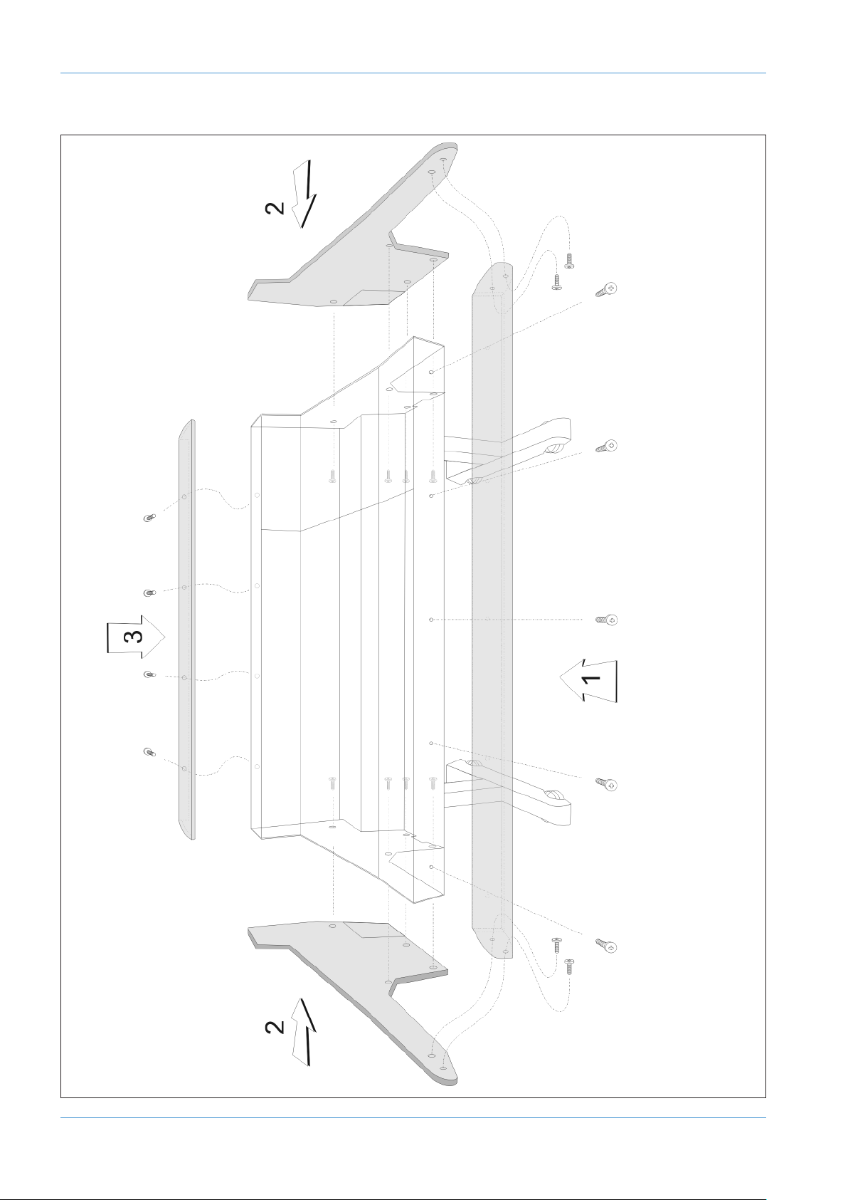
REMOVING THE TRIM
If it is necessary to remove the trim panels – to adjoin existing furniture – then please refer to the following information
and the illustration shown on the facing page.
Note that it is not necessary to remove any of the audio modules to gain access to the trim fixing screws.
FRONT BUFFER
The front buffer [1] is secured by nine pan-head screws – five in the front beam and two in each end trim. These are all
visible from beneath the buffer.
END TRIM
Each of the end trims [2] is secured by four countersunk Posi-head screws through the profile (one is located in the kneepanel area, two more are found either side of the main beam and the fourth is located on the bottom corner of the outside
profile), as well as two pan-head screws through the front buffer (visible from beneath the buffer).
TOP TRIM
The top trim [3] is clipped over the front of the meter panels and secured onto the back panels by four M3 screws.
AWS δelta Owner’s Manual Page 1-3
Page 26
Pre Installation
EXT A1 EXT A2
EXT A3 EXT A4
METER
OUT
EXT B
1 - 4
SEND - MON - RET
INSERT
MIC
INST
LINE
SEND
RTN
DIR
T/BACK
MIC OUT
LISTEN
MIC OUT
T/BACK
MIC IN
LISTEN
MIC IN
MINI
AL
MINI
AR
MINI
BL
MINI
BR
OSC
OUT
MON B MON A
SEND
LEFT
RETURN
LEFT
SEND
RIGHT
RETURN
RIGHT
LEFT
OUT
RIGHT
OUT
MIX OUTPUT
SEND
LEFT
RETURN
LEFT
SEND
RIGHT
RETURN
RIGHT
LEFT
OUT
RIGHT
OUT
REC OUTPUT
ECHO
RTN 1L
ECHO
RTN 1R
FX1
OUT
KEY
IN
FB AL
OUT
FB AR
OUT
ECHO
RTN 2L
ECHO
RTN 2R
FX2
OUT
KEY
IN
FB BL
OUT
FB BR
OUT
ECHO
RTN 3L
ECHO
RTN 3R
FX3
OUT
ECHO
RTN 4L
ECHO
RTN 4R
FX4
OUT
8 TRACK
BUS OUT
CUE/FX
BUS OUT
RED LIGHT / TALKBACK / GP I/O
CUE BUS INJECTS
MIC GAIN
DESK
EXT TB
L INSERT R
MIC
SEND
RTN
VIDEO
OUT
NETWORK SERIAL 2
(DIAGNOSTICS)
SERIAL 1
(X-RACK)
RESET SD-CARD
21
FOOTSWITCH
MIDI 1
IN OUT
MIDI 2
IN OUT
MIDI 3
IN OUT
MIDI 4
IN OUT
MIDI 5
IN OUT
MIDI 6
IN OUT
L CH OUT R
LINE L /MON
LINE R
(948)
Stereo
Channels
Mono
Channels
(916 and 924)
Processor Interface and MIDI
Master Section
GP IO
Page 1-4 AWS δelta Owner’s Manual
Page 27

i
Studio Integration
Title:
Client:
Sheet:
Revision:
Drawn by:
Date:
21/09/10
GC
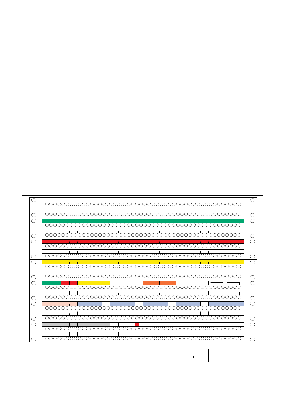
AWS 924 Patch layout proposal
Standard Configuration
924 0.1
Solid State Logic
SOUND V SI ION
Notes:
1. Patchrow AB is isolated
2. D31 is linked to C33, 35, 37, 39
3. D32 is linked to C34, 36, 38, 40
4. J31 is linked to J32
5. Links at G33–36, G37–40, J33–36,
J37–40, K33–36, K37–40,
Normalling Information:
Fully normalled: AB 1–24, JK 29
No normalling: AB 25–48, GH 33–40, JK 33–40
All other jacks are half-normalled
1234
F
X IN
LR
C
UE A
LR
C
UE B FX SENDS
1234L RLR
E
CHO RETURN IN
1L 1R 2L 2R 3L 3R 4L 4R
F
X OUT
1
L1R2L2R3L3R4L4R
1L 1R 2L 2R 3L 3R 4L 4R
1L 1R 2L 2R 3L 3R 4L 4R
E
XT B IN
S
TEREO REPLAY
R
EC
INSERT
R
EC
OUTPUT
LRL
R
ETURN
R
M
IX
INSERT
M
IX
OUTPUT
L
R
ETURN
R
D
IST IN
LR
M
IX DISTRIBUTION OUT
LRL RL RL R
1L 1R 2L 2R 3L 3R 4L 4R
8
TK RECORDER IN
T
RACK BUS OUT
12345678
12345678
E
XT A 6TK 4
LRCLFELSRS
E
XT A 6TK 3
LRCLFELSRS
E
XT A 6TK 2
LRCLFELSRS
E
XT A 6TK 1
LRCLFELSRS
LRCLFELSRSLRCLFELSRSLRCLFELSRS
6
TRACK REPLAY 1
LRCLFELSRS
6
TRACK REPLAY 2 6 TRACK REPLAY 3 6 TRACK REPLAY 4
M
AIN LS B
L
R
M
INI B
M
AIN LS A
AMP IN
LRCLFELSRS
L
R
M
INI A
LR
A
MP INAMP IN
LR
A
MP IN
L
RCLFELSRS
LRCLFELSRS
L
RCLFELSRS
1
7181920212223249 10 11 12 13 14 15 161 2345678 25 26 27 28 29 30 31 32 33 34 35 36 37 38 39 40 41 42 43 44 45 46 47 48
1
7181920212223249 10 11 12 13 14 15 161 2345678 25 26 27 28 29 30 31 32 33 34 35 36 37 38 39 40 41 42 43 44 45 46 47 48
D
IRECT OUTPUTS
9101112131415161 234567 8 1718192021222324
C
HANNEL INSERT SENDS
1
7181920212223249 10 11 12 13 14 15 161 2345678 25 26 27 28 29 30 31 32 33 34 35 36 37 38 39 40 41 42 43 44 45 46 47 48
17 18 19 20 21 22 23 249 10 11 12 13 14 15 161 2345678 25 26 27 28 29 30 31 32 33 34 35 36 37 38 39 40 41 42 43 44 45 46 47 48
1
7181920212223249 10 11 12 13 14 15 161 2345678 25 26 27 28 29 30 31 32 33 34 35 36 37 38 39 40 41 42 43 44 45 46 47 48
1
7181920212223249 10 11 12 13 14 15 161 2345678 25 26 27 28 29 30 31 32 33 34 35 36 37 38 39 40 41 42 43 44 45 46 47 48
1
7181920212223249 10 11 12 13 14 15 161 2345678 25 26 27 28 29 30 31 32 33 34 35 36 37 38 39 40 41 42 43 44 45 46 47 48
17 18 19 20 21 22 23 249 10 11 12 13 14 15 161 2345678 25 26 27 28 29 30 31 32 33 34 35 36 37 38 39 40 41 42 43 44 45 46 47 48
M
IC LINES
U
SER OPTION
9
10 11 12 13 14 15 161 234567 8 1718192021222324 9101112131415161 234567 8 1718192021222324
CHANNEL MIC INPUTS
9101112131415161 234567 8 1718192021222324 9101112131415161 234567 8 1718192021222324
DAW OUTPUTS
9101112131415161 234567 8 1718192021222324
CHANNEL LINE INPUTS
D
AW INPUTS
9101112131415161 234567 8 1718192021222324
C
HANNEL INSERT RETURNS
IN
L
SN
O
UT
L
SN
O
UT
T
/B OSC
17 18 19 20 21 22 23 249 10 11 12 13 14 15 161 2345678 25 26 27 28 29 30 31 32 33 34 35 36 37 38 39 40 41 42 43 44 45 46 47 48
17 18 19 20 21 22 23 249 10 11 12 13 14 15 161 2345678 25 26 27 28 29 30 31 32 33 34 35 36 37 38 39 40 41 42 43 44 45 46 47 48
L
RLR
F
/B A OUT F/B B OUT
LR
A
MP A
LR
A
MP B
M
ONITOR INSERT SEND
Lt Rt
D
ECODER
MONITOR INSERT RTN
LRCLFELSRS
Lt Rt
ENCODER
L
RCLFELSRS
USER OPTION
A
B
C
D
E
F
G
H
J
K
9
10 11 12 13 14 15 161 234567 8 1718192021222324
9
10 11 12 13 14 15 161 234567 8 1718192021222324
9101112131415161 234567 8 1718192021222324
CUE A 12 34
B
US INJECT IN
FXCUE B
STUDIO INTEGRATION
AUDIO CONNECTIONS
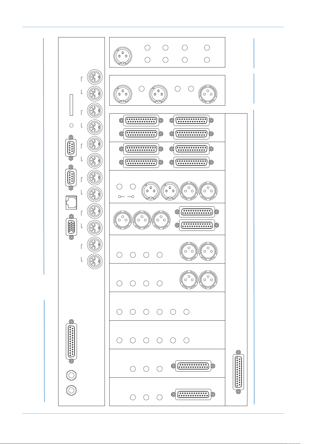
All connections to the AWS – apart from the two headphone jacks – are located on the rear panels of the console. The
headphone sockets are located on the Centre Section knee panel.
The console rear panel is fitted with a label which identifies all the connections on the connector panel, and provides the
pinout for each one (the detail is shown opposite). This information is also provided in the Appendices section of this
manual.
All connections are balanced.
All 25-way D-type connectors use screw pillars that utilise the UNC-440 thread.
See the appendices for the pinouts of all audio connectors.
CONNECTING A PATCHBAY
The AWS may, of course, be fully or partially integrated to an external patchbay. 3rd party options are available and SSL
can provide patchbay solutions as cost options – contact your local SSL distributor for further information.
AWS δELTA 916-924 PATCHBAY LAYOUT EXAMPLE:
It is recommended that the above 24-channel layout is also used for AWS 916 consoles; doing so will greatly simplify a future
upgrade to an AWS 924 console.
AWS δelta Owner’s Manual Page 1-5
Page 28
Studio Integration
Title:
Client:
Sheet:
Revision:
Drawn by:
Date:
30/06/16
GC
AWS Delta 948 Patch layout
Standard Configuration
948 1.0
Solid State Logic
SOUND V SI ION
Notes:
1. Patchrow AB is isolated
2. Links at: J41–44, J45–48
K41–44, K45–48
Normalling Information:
Fully normalled: AB 1–24, NP 21
No normalling: AB 25–48, JK 41–48, NP 22–48
All other jacks are half-normalled
1
7181920212223249 10 11 12 13 14 15 161 2345678 25 26 27 28 29 30 31 32 33 34 35 36 37 38 39 40 41 42 43 44 45 46 47 48
17 18 19 20 21 22 23 249 10 11 12 13 14 15 161 2345678 25 26 27 28 29 30 31 32 33 34 35 36 37 38 39 40 41 42 43 44 45 46 47 48
D
IRECT OUTPUTS
CHANNEL INSERT SENDS
1
7181920212223249 10 11 12 13 14 15 161 2345678 25 26 27 28 29 30 31 32 33 34 35 36 37 38 39 40 41 42 43 44 45 46 47 48
17 18 19 20 21 22 23 249 10 11 12 13 14 15 161 2345678 25 26 27 28 29 30 31 32 33 34 35 36 37 38 39 40 41 42 43 44 45 46 47 48
1
7181920212223249 10 11 12 13 14 15 161 2345678 25 26 27 28 29 30 31 32 33 34 35 36 37 38 39 40 41 42 43 44 45 46 47 48
17 18 19 20 21 22 23 249 10 11 12 13 14 15 161 2345678 25 26 27 28 29 30 31 32 33 34 35 36 37 38 39 40 41 42 43 44 45 46 47 48
17 18 19 20 21 22 23 249 10 11 12 13 14 15 161 2345678 25 26 27 28 29 30 31 32 33 34 35 36 37 38 39 40 41 42 43 44 45 46 47 48
17 18 19 20 21 22 23 249 10 11 12 13 14 15 161 2345678 25 26 27 28 29 30 31 32 33 34 35 36 37 38 39 40 41 42 43 44 45 46 47 48
MIC LINES USER OPTION
9101112131415161 23456 78 1718192021222324 9101112131415161 2345678 1718192021222324
CHANNEL MIC INPUTS
9
10 11 12 13 14 15 161 23456 78 1718192021222324 9101112131415161 2345678 1718192021222324
DAW OUTPUTS
9101112131415161 23456 78 1718192021222324
CHANNEL LINE INPUTS
D
AW INPUTS
9101112131415161 23456 78 1718192021222324
C
HANNEL INSERT RETURNS
5L 5R 6L 6R 7L 7R 8L 8R1L1R2L2R3L3R4L4R 9L9R10L10R11L11R12L12R 17L17R18L18R19L19R20L20R13L 13R 14L 14R 15L 15R 16L 16R 21L 21R 22L 22R 23L 23R 24L 24R
5
L5R6L6R7L7R8L8R1L1R2L2R3L3R4L4R 9L9R10L10R11L11R12L12R 17L17R18L18R19L19R20L20R13L 13R 14L 14R 15L 15R 16L 16R 21L 21R 22L 22R 23L 23R 24L 24R
17 18 19 20 21 22 23 249 10 11 12 13 14 15 161 2345678 25 26 27 28 29 30 31 32 33 34 35 36 37 38 39 40 41 42 43 44 45 46 47 48
17 18 19 20 21 22 23 249 10 11 12 13 14 15 161 2345678 25 26 27 28 29 30 31 32 33 34 35 36 37 38 39 40 41 42 43 44 45 46 47 48
MONITOR INSERT SEND
Lt Rt
DECODER
MONITOR INSERT RTN
LRCLFELSRS
Lt Rt
ENCODER
LRCLFELSRS
1L 1R 2L 2R 3L 3R 4L 4R
1L 1R 2L 2R 3L 3R 4L 4R
EXT B IN
STEREO REPLAY
USER OPTION
33 34 35 36 37 38 39 402526272829303132 4142434445464748
5L 5R 6L 6R 7L 7R 8L 8R1L1R2L2R3L3R4L4R 9L9R10L10R11L11R12L12R 17L17R18L18R19L19R20L20R13L 13R 14L 14R 15L 15R 16L 16R 21L 21R 22L 22R 23L 23R 24L 24R
1
7181920212223249 10 11 12 13 14 15 161 2345678 25 26 27 28 29 30 31 32 33 34 35 36 37 38 39 40 41 42 43 44 45 46 47 48
17 18 19 20 21 22 23 249 10 11 12 13 14 15 161 2345678 25 26 27 28 29 30 31 32 33 34 35 36 37 38 39 40 41 42 43 44 45 46 47 48
R
EC
1234
F
X IN
LR
C
UE A
LR
C
UE B FX SENDS
1234ALARBLBR
INSERT
R
EC
OUTPUT
LRL
RETURN
R
M
IX
INSERT
M
IX
OUTPUT
L
RETURN
R
DAW IN
LR
CUE A 12 34
BUS INJECT IN
FX
CUE B
DAW IN
T
RACK BUS OUT
12345678
12345678
5L 5R 6L 6R 7L 7R 8L 8R1L1R2L2R3L3R4L4R 9L9R10L10R11L11R12L12R 17L17R18L18R19L19R20L20R13L 13R 14L 14R 15L 15R 16L 16R 21L 21R 22L 22R 23L 23R 24L 24R
33 34 35 36 37 38 39 402526272829303132 4142434445464748
DAW IN
D
AW OUT
12345678
E
CHO RETURN IN
1L 1R 2L 2R 3L 3R 4L 4R
F
X OUT
1L 1R 2L 2R 3L 3R 4L 4R
ALT LS
LR
MINI B
MAIN LS
AMP IN AMP IN
LR
AMP IN
LRCLFELSRS
LRCLFELSRS
LRCLFELSRS
IN
LSN
OUT
LSN
OUT
T/B OSC
17 18 19 20 21 22 23 249 10 11 12 13 14 15 161 2345678 25 26 27 28 29 30 31 32 33 34 35 36 37 38 39 40 41 42 43 44 45 46 47 48
17 18 19 20 21 22 23 249 10 11 12 13 14 15 161 2345678 25 26 27 28 29 30 31 32 33 34 35 36 37 38 39 40 41 42 43 44 45 46 47 48
LRLR
F/B A OUT F/B B OUT
LR
AMP ALRAMP B
LRCLFELSRS
LR
MINI A
LR
AMP IN
IN
T/B
USER OPTION
9101112131415161 234567 8 1718192021222324
9101112131415161 234567 8 1718192021222324
USER OPTION
LRCLFELSRS
EXT A1
5.1 REPLAY
LRCLFELSRS
EXT A2
5.1 REPLAY
LRCLFELSRS
EXT A3
5.1 REPLAY
LRCLFELSRS
EXT A4
5.1 REPLAY
PATCHBAY GUIDELINES
STRUMENTINPUTS
IN
916
(
A
ND
24 O
9
LY
N
)
It is not recommended that the ‘Instrument’ inputs are broken out to a patchbay. These inputs are unbalanced and have a
high input impedance. Accordingly, to help avoid the pickup of noise and interference, cables should be kept at short as
possible.
LINELE
VELINPUT
/OU
TPUTS
All other analogue inputs and outputs can be connected via a patchbay. It is recommended that the cable shield is
connected at the console end and disconnected at the patch row to avoid ground loops. Wiring to the installation should
normally have the shield connected to the patch row. The shield connection of all jacks should be linked together (note
that patch rows with solid metal front panels will automatically do this) and then linked to a common star point on the
patchbay. This starpoint can then be returned – via a thick grounding cable (6mm sq. or greater) – to the chassis stud on
the rear of the AWS console. This will reduce the risk of earth loops within the installation.
The screen pins of all analogue inputs and outputs – with the exception of the microphone inputs – are connected directly
to the chassis of the AWS console.
MIC INPUTS
If Microphone inputs are to be connected via a patchbay, the type of patch-row used should be of the insulated variety
where the jack screens are not connected to the main body of the patch-row – there are commercially available patchrows that meet this requirement. The ground connection from each microphone must be linked through the patch jacks
to the XLR on the back of the console without interruption.
AWS δELTA 948 PATCHBAY LAYOUT EXAMPLE:
A
B
C
D
E
F
G
H
J
K
L
M
N
P
Page 1-6 AWS δelta Owner’s Manual
Page 29

DAW Connection
CONNECTING YOUR DAW
he AWS console communicates with a DAW directly via Ethernet or via three MIDI ports. To use the Ethernet option
T
a third party ipMIDI software driver must be installed on the DAW computer. Registered owners can download this from
the SSL website:
a wide variety of DAW applications on a wide variety of platforms. The AWS uses Mackie control or a ‘HUI’ compatible
protocol, and so any DAW program that can be configured to use three HUI devices can access the full power of the
WS.
A
Please refer to your DAW manual for details on how to configure the DAW application for AWS under Mackie or HUI
control.
OVERVIEW
In normal operation the AWS uses an Ethernet connection for DAW control and the SSL AWS Remote for session
management. The next section describes how to download and install the ipMIDI driver and AWS Remote on Macintosh
and PC.
Optionally the AWS can use a standard MIDI connection between the AWS console and your DAW using a multi port
MIDI interface. In this mode only one DAW layer can be configured. The console communicates with the DAW via the
MIDI ports located on the rear of the console – details are provided at the end of this section.
www.update.solidstatelogic.com. Using these methods of communication allows the AWS to be used with
INSTALLING THE IPMIDI DRIVER AND AWS REMOTE
Download on to your workstation computer either the AWS924-948_Mac_Support.dmg disk image (Macintosh) or the
AWS924-948_Win_Support.zip file (Windows). These contain the AWS Remote and ipMIDI applications and the latest
version of the installation instructions:
http://update.solid-state-logic.com/update/public/index.jsp
System Requirements for your workstation computer: AWS Remote is a Java application. It will run under Java Version 5
or higher. ipMIDI is compatible with Windows 2000 (maximum 9 MIDI ports), XP, Vista and Windows 7, and Macintosh
OS X 10.4 upwards.
SOFTWARE INSTALLATION (MACINTOSH)
Mount the AWS924-948_Mac_Support.dmg disk image and open it.
AWS Remote: Double-click on the AWS Remote application to install.
ipMIDI: Double click on the ipMIDI.pkg file to run the installation program. Note that you will be asked to log out and in
again once you have completed the installation. Once you have logged back in open Audio MIDI Setup, select the MIDI
tab and double click on the ipMIDI icon. Set the number of MIDI ports to 10 in the resulting pop-up.
If you are upgrading an older copy of ipMIDI you must uninstall it before running the installer. To uninstall ipMIDI simply
delete: </Library/Audio/MIDI Drivers/ipMIDIDriver.bundle>. You should empty the Trash after deleting the bundle file before
running the installer.
The drivers mentioned above are also suitable for the AWS 916 console
AWS δelta Owner’s Manual Page 1-7
Page 30
DAW Connection
SOFTWARE INSTALLATION (PC)
Open the AWS924-948_Win_Support.zip archive.
AWS Remote: Double click on AWS924-948Remote.exe to install the program.
ipMIDI: Run the setupipmidi_1.8.exe application (note that the last part of the name may change depending on the version
you are installing) by double clicking on it. Note that you will have to restart the computer at the end of the setup process.
Once the computer has restarted right click on the ipMIDI icon in the task bar and set the number of MIDI ports to 10
in the resulting pop-up.
If you are upgrading an older copy of ipMIDI you must uninstall it (using Add/Remove programs) before running the installer.
MAKE AND CONFIGURE THE NETWORK CONNECTION
The AWS Remote software is designed to communicate with your workstation over Ethernet using the ipMIDI driver to
emulate a multiport MIDI interface. The ipMIDI driver enables your workstation to send and receive MIDI control data
via a network connection. Using Ethernet ensures the fastest possible communication between your workstation
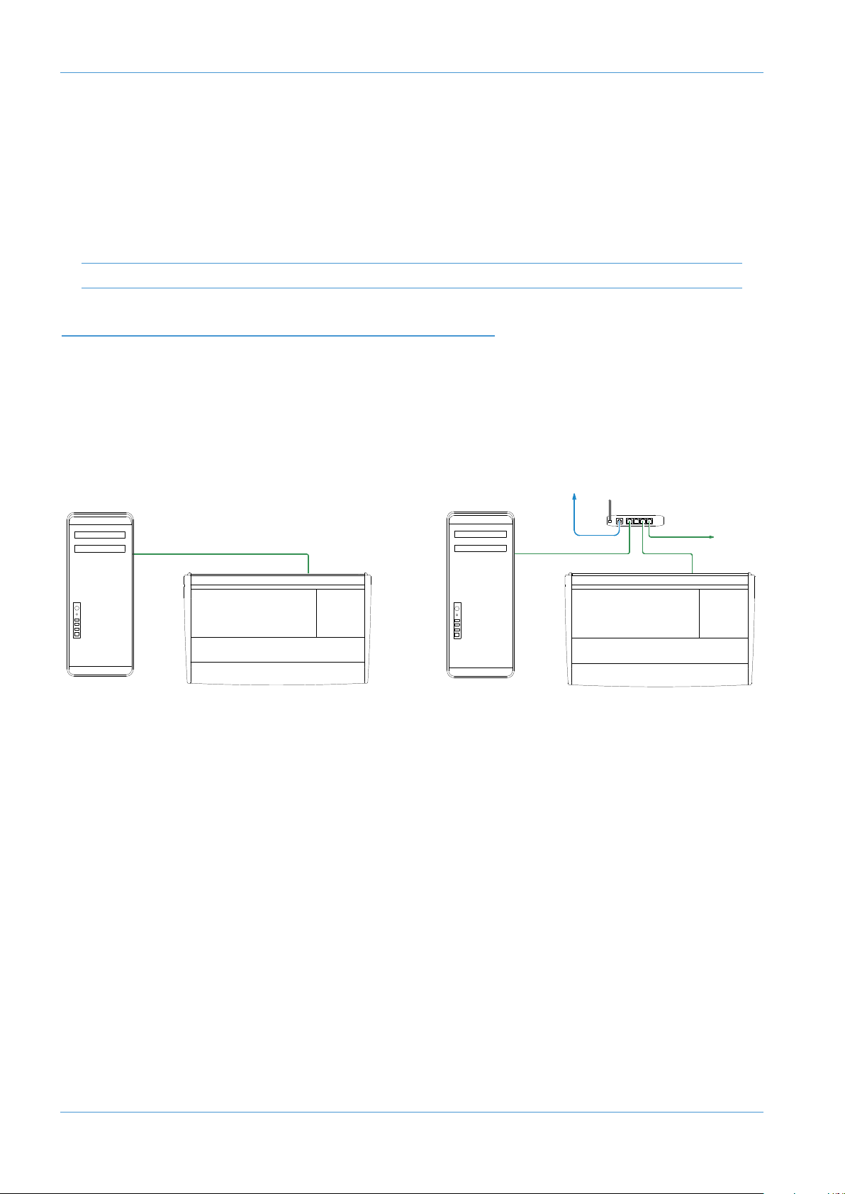
computer and AWS. The standard direct connection uses an RJ45 crossover network cable (not supplied) to connect the
console’s network connector directly to the network port on your workstation computer using the console’s default fixed
IP address of 192.168.1.2. Note that many computer adaptor cards will autosense a direct connection negating the need for a
crossover cable. If you are unsure whether your workstation computer’s network adapter has this functionality, please use a crossover
rather than a pin to pin cable.
LAN
Direct Connection Connection via DHCP Router
It is possible to connect AWS to a larger network which incorporates multiple computers and to enable dynamic (DHCP)
addressing. These configurations need special consideration. Please see the notes at the end of these instructions for
details.
DIRECT NETWORK CONNECTION (MACINTOSH)
Please note that currently OS X does not allow two ports to be used for IP traffic. As such, the connection to your main
network will not be available while the AWS is connected.
To simplify the process of switching between networks, it is recommended that you create a new network Location for
the AWS in network preferences. Another Location (‘internet’ for example) could be created to enable connection to the
internet. This would use the network settings provided by your Internet Service Provider or network administrator. You
can easily switch between network Locations by going to the Apple Menu and scrolling down to Location.
Page 1-8 AWS δelta Owner’s Manual
Page 31

DAW Connection
• Using an RJ45 cable, make a direct network connection between the network port on your AWS to a network port
n your workstation computer and check that the IP address is set to FIXED in the console’s
o
SSL > MISC > NET menu.
• Open System Preferences and click on Network. Create a new location by clicking where it says Location, scroll down
to Edit Locations and click the ‘+’ sign. Name the new location AWS.
• Next, select the Ethernet port which is connected your AWS and configure as shown below:
New ‘AWS’
Ethernet must
be the primary
interface
Location
Must match the
AWS IP address
• If your Macintosh features multiple network ports, you should set the priority of these so that the Ethernet port
connected to your AWS is at the top of the list.
• Alternatively, if you have already created a separate Location for your existing network you can simply delete the
unused ports (Airport, Firewire) from the AWS location so that only the network port connected to AWS is
remaining.
Please note that currently OS X does not allow two ports to be used for IP traffic. As such, the connection to your main
network will not be available while the AWS is connected.
Note also that if your workstation computer is a Mac, you should ensure that your Mac Airport is switched off. We strongly
recommend this as Airport is known to cause conflicts with ipMIDI data. If you wish to use the internet, we suggest you
configure AWS with a Router/Switch (see Connection Using DHCP).
AWS δelta Owner’s Manual Page 1-9
Page 32

DAW Connection
DIRECT NETWORK CONNECTION (PC)
To set up the connection:
• Double click on Network Connections in Start/Control Panel. Right click on the network adapter connected to your
AWS (likely to be called “Local Area Connection”). Select Properties.
• Select Internet Protocol (TCP/IP) and Properties.
• Next, configure the adapter as shown below:
Must match the
AWS IP address
• Click on OK on both windows to save. Back in your network connection list, right click on your adaptor and ensure
that it is enabled. If it is disabled, the enable option will appear in the list. Click on enable.
Page 1-10 AWS δelta Owner’s Manual
Page 33

DAW Connection
NETWORK CONNECTION USING DHCP
If the AWS is being connected to the DAW workstation via a Local Area Network (LAN), a DHCP enabled router with
at least 3 Ethernet ports will be required. The principle behind this method is that your Internet router acts as a DHCP
server, dynamically assigning IP addresses to all the devices on your network. The simplest configuration would be as
hown above.
s
DHCP SETTINGS (MACKINTOSH)
• On the Mac, go to System Preferences and click on
the Network icon.
• Set Configure IPv4 to Using DHCP.
DHCP SETTINGS (WINDOWS)
• Go to Network and go into Local Area Connection
Properties.
• Open up the option Internet Protocol version 4 (TCP/IPv4).
• Choose the option Obtain an IP address automatically.
AWS δelta Owner’s Manual Page 1-11
Page 34

DAW Connection
ENABLING IPMIDI ON YOUR AWS
In the SSL > MISC > SETUP menu, toggle the ‘MIDI connects via:’ setting to ‘Network’. Your console will now
communicate with your workstation via Ethernet. With ‘MIDI connects via:’ set to ‘MIDI ports’, AWS will communicate
with your workstation via the conventional MIDI connectors on the rear of your console.
You will need to reboot the console after changing this option.
Also in the SSL > MISC > SETUP menu, ensure that the ‘DAW’ option (workstation layer 1) and DAW2 (workstation
layer 2) are set to match your workstation or workstations if you are using the second layer. Please note that you will
eed to restart the console after making a change to the DAW layer options.
n
NDING THECONSOLE ON THE
FI
Launch AWS Remote on your workstation. If you only have one AWS console on the network, AWS Remote will
automatically locate the console and the message ‘AWS 948-924 SN xxxxx is online’ (where xxxxx is the ID of
the console) will be shown in green text in the bottom left hand corner of the browser:
If you have multiple AWS consoles on the network or the AWS Remote browser did not automatically locate your
console ‘No AWS 924-948 connected’ will be shown in red text. In this instance, click on the find icon . If the
list is empty, click on Find, select the console you wish to connect to and click on select.
AWS RE
MOTEAPPLICATION
If your console does not appear in the list, it suggests you have a network related issue. Please follow the steps in the
network trouble shooting section at the end of this document to resolve the issue.
Once you have made this selection, the AWS Remote will automatically connect to the selected console and display the
‘AWS 948-924 SN xxxxx is online’ message. To connect to a different console, click on the find icon and
change your selection.
Page 1-12 AWS δelta Owner’s Manual
Page 35

DAW Connection
SETTING YOUR WORKSTATION(S) TO COMMUNICATE VIA IPMIDI
The AWS software uses 10 virtual MIDI ports which are pre-assigned as follows:
Port Layer Assignment Port Layer Assignment
1 1 Faders 1–8 7 – MTC/MMC input *
2 1 Faders 9–16 8 – SysEx
3 1 Faders 17–24 9 – AWS MIDI Port 1
4 2 Faders 1–8 10 – AWS MIDI Port 2
5 2 Faders 9–16
6 2 Faders 17–24
* Note that MIDI port 4 or ipMiDI port 7 can be used for MTC input thereby allowing MTC to be connected from systems
(such as RADAR) that do not support the ipMIDI driver. MTC should only be routed to one port at a time.
• Note that there are now two switchable workstation layers allowing independent workstations to be interfaced.
Once configured, you can switch between the two layers using the console’s SSL > DAW menu. Port 7: This port
is used for the timecode display with δ-Control automation and as the reference input with legacy automation.
• Port 8: Used for the import of legacy SysEx TR and SSL automation data saved under earlier software versions.
• Port 9-10: Mapped to the conventional MIDI connectors on the rear of the console allowing connection of a keyboard
or other MIDI device to your DAW via ipMIDI .
To select which DAW is assigned to each layer go to SSL > MISC > SETUP on your console and select the following:
DAW 1: select from Protools HUI / Nuendo / Digital Performer / Sonar
DAW 2: select from Protools HUI / Nuendo / Digital Performer / Sonar / None
After making these changes the console should be restarted.
To enable control of your workstation via HUI or MCU your workstation(s) must be configured to match the appropriate
layer in the list above. This is done using the MIDI Controller configuration page of your workstation.
The following page shows an example using Pro Tools.
AWS δelta Owner’s Manual Page 1-13
Page 36

DAW Connection
PRO TOOLS
In the Setup menu, click on Peripherals and select the MIDI Controllers tab. Using MIDI controllers 1, 2 (916) and 3 (924-
948), select HUI as the MIDI controller Type and assign the MIDI ports for this layer’s DAW to the two MIDI controllers,
as listed in the table above. If Pro Tools has been assigned to Layer 1, the MIDI Controllers window should look like this:
To use the timecode display in δ-Control or to run legacy automtion, set the MTC generator port in the Synchronization
tab to ipMIDI port 7 (or AWS MIDI port 4 if you are using the console MIDI ports):
Also, set the MMC MIDI port in the Machine Control tab to ipMIDI port 7 (or AWS MIDI port 4 if you are using the
console MIDI ports):
Enable the two options shown above to ensure that the desk MTC reader shows the correct position following a Pro Tools
locate or scrub operation.
The legacy automation system automatically detects the timecode standard from the incoming MTC messages but will quite
happily attempt to play out stored mix data to incoming timecode with a different frame rate. This will result in small but
potentially annoying timing errors in automation playback as well as missing data if 25 frame timecode is used to play back
a Mix recorded with 30 frame timecode.
To make Pro Tools behave like a tape machine for SSL Legacy Automation enable the following in the Pro Tools Setup /
Preferences / Operation menu :
1. Timeline Insertion/Play Start Marker Follows Playback
2. Edit Insertion Follows Scrub/Shuttle
Page 1-14 AWS δelta Owner’s Manual
Page 37

DAW Connection
NETWORK TROUBLESHOOTING
Most Ethernet adaptor cards have two LEDs associated with each port. The one indicates that the link is connected and
the other indicates network traffic. Please note that some Macintosh computers do not have external LEDs to indicate
status. Instead the link status is shown in the System Preferences/Network menu.
On your host workstation computer, confirm that the link LED is permanently illuminated. If it is not permanently
illuminated, it suggests you have a cabling error. In this instance please check the following:
• The RJ45 network connector on the console and on your workstation are fully inserted.
• If you are using a pin-pin cable to make a direct connection between your console and workstation, try replacing it
with a crossover cable.
• Try replacing the network cable.
• If you are not using a direct connection between your console and workstation using the default fixed IP address on
the console, please try this simple configuration to rule out issues with external routers and network switches. If the
link LED is illuminated, the next step is to confirm that the activity LED is illuminating periodically to show network
traffic. If it does not illuminate periodically check the following:
• If your workstation is not connected directly to your console using a crossover RJ45 cable and fixed IP addressing,
follow the installation instructions to configure this simple network configuration to rule out issues with any external
routers or network switches.
• Using the fixed default IP address on the console, check that the workstation has basic communications using ‘ping’:
Windows:
Select Run under the Start menu. In the resulting window enter cmd to launch the command prompt. In the
command prompt window type ping 192.168.1.2
Macintosh OSX:
Open a Finder window, select Applications, then Utilities, and double-click on Terminal. In the terminal window
enter ping –c4 192.168.1.2
In both cases your host computer will try to establish communications with your console. In the resultant terminal
text, check that the console responded to every message sent by your workstation.
AWS δelta Owner’s Manual Page 1-15
Page 38

DAW Connection
LARGER NETWORKS
Firewall
Router
To ensure minimum latency the ipMIDI driver uses broadcast UDP rather than TCP/IP. This means that:
• The network connection should be as short as possible and should only use routers that can support high data transfer
rates. Problems have been experienced with some domestic routers, particularly when used with Pro Tools.
• Because ipMIDI uses broadcast UDP packets, messages between one computer and AWS will be received by all other
computers on the network, potentially causing problems in installations with more than one AWS. The UDP packets
can be blocked by using a firewall router and connecting the main network to the WAN connector. The firewall can
then be configured to allow all traffic apart from UDP ports 21928 through 21947 which are used by ipMIDI and
(optionally) port 50081 which is used by the AWS Remote application. Most systems can be easily configured with a
direct connection between AWS and the controlling computer.
Page 1-16 AWS δelta Owner’s Manual
Page 39

ASSIGNING THE AWS IP ADDRESS
When shipped from the factory, the AWS uses a fixed IP address of 192.168.1.2.
DAW Connection
USING D
Alternatively, dynamic (DHCP) address can be selected via the SSL > MISC > NET menu. The currently assigned address
s also shown in the MISC > ABOUT > NET menu. If your AWS is connected to the computer via a network switch
i
or router, it should be assigned a DHCP IP address; otherwise the fixed option should be used. If you have altered the IP
mode, you will need to restart your AWS for the change to take effect. A software restart option is available in the
SSL > MISC > NET menu.
HCP
CHANGING THE STATIC IP ADDRESS
The default fixed IP address can be altered using the console diagnostic port. This should only be necessary where the
default address is already in use at an installation.
You will need a PC or Mac running terminal emulator software. Connect your computer’s serial port to the rear of the
console using a 9 way ‘D’ type extension cable. The pin out for the console’s 9 way ‘D’ type serial connector is shown
below:
Pin Description
1 Carrier (linked to 0V)
2 Tx
3 Rx
4 DTR (linked to DSR)
5 0V
6 DSR (linked to DTR)
7 RTS (linked to CTS)
8 CTS (linked to RTS)
9 RI (linked to 0V
A standard male – female pin-to-pin 9-way D-type lead can be used for serial connection.
Set the terminal as follows: Baud rate 19200, 8 data bits, No parity, No start bit, 1 stop bit, Flow control Xon/Xoff
Press the ‘
To set the IP address type the following (note that the spaces are required between the number groups):
Return
’ key (<CR>) and the terminal window should echo a ‘>’ if communication is established.
ip<CR>
setip nnn nnn nnn nnn<CR>
setmask 255 255 255 0<CR>
setgate nnn nnn nnn nnn<CR>
where ‘nnn...’ is the required IP address.
Note that this number should match other devices local to the console.
where ‘nnn...’ is the gateway address e.g. ‘10 1 1 1’
AWS δelta Owner’s Manual Page 1-17
Page 40

IN OUT IN OUT IN OUT IN OUT IN OUT IN OUT
MIDI 1 MIDI 2 MIDI 3 MIDI 4 MIDI 5 MIDI 6
INO
UTINOUTINOUTINOUTINOUTINOUT
i
DAW Connection
USING PHYSICAL MIDI PORTS TO CONNECT YOUR DAW
Optionally the AWS can use a standard MIDI connection between the AWS console and your DAW using a multi port
MIDI interface. In this mode only one DAW layer can be configured. To select this mode navigate to the SSL > Misc >
Setup menu and set MIDI communicates via: MIDI Ports.
The console communicates with the DAW via the MIDI ports located on the rear of the console:
AWS MIDI
Ports
DAW MIDI
orts
P
MIDI ports should be connected to your DAW MIDI interface unit – three available ports are required (one port includes
an IN and OUT socket). To connect a port, the output of the MIDI interface unit port 1 should connect to the MIDI 1
input port of the AWS and the MIDI output of the AWS port 1 should connect to the input of your MIDI interface unit
port 1. Repeat for the other ports using the diagram above as a guide. Port 4 is used both for archiving Total Recall and
Automation data and to receive MIDI Timecode (MTC).
Follow the instructions on configuring your workstation but use the physical MIDI ports rather than the virtual MIDI ports
when selecting MIDI ports.
Ports 5 and 6 are currently not implemented and are reserved for future expansion.
The recommended maximum length of MIDI cables is 15 meters.
OTHER CONNECTIONS
Serial 1 – X-Rack control data. Refer to X-Rack installation manual.
Serial 2 – Diagnostics (SSL Service use)
GP IO – Talkback, Red Light, CUT and DIM trigger inputs. Refer to Appendix C for details.
VGA – 640 x 480 (60Hz) External monitor output.
Page 1-18 AWS δelta Owner’s Manual
Page 41

AWS δelta
916-924-948
OWNER’S MANUAL
SECTION 2
A – AWS 916 & 924 TUTORIAL
2
2B – AWS 948 TUTORIAL
Page 42

Contents
SECTION CONTENTS
Introduction 2a-iv
δELTA 916-924 Tutorial 2a-1
tudio Configurations 2a-1
S
maller Systems 2a-1
S
arger Systems 2a-1
L
Focus Modes 2a-2
916-924 Channel Strip 2a-3
Input configuration 2a-3
Signal Processing 2a-3
Dynamics 2a-3
Filter and EQ 2a-3
Insert Point 2a-3
Routing 2a-3
Cue, FX and EFX Sends 2a-3
Bus Routing 2a-4
Panning, Width and Balance 2a-4
Level, Cuts and Solos 2a-4
Centre Section 2a-5
Adjusting the Mix and Record Busses 2a-5
Creating a Monitor Mix 2a-5
Creating Foldback Mixes 2a-5
Using the FX Returns 2a-5
Using Talkback 2a-5
‘In-line’ Recording 2a-5
Page 2a-ii AWS δelta Owner’s Manual
Page 43

δELTA 948 Tutorial 2b-1
Focus Modes 2b-1
Channel Modes 2b-3
asic Tracking Configuration 2b-4
B
Mono Configuration 2b-4
Stereo Configuration 2b-4
Analogue-Style In-Line Tracking Configuration 2b-5
Band Tracking Mode 2b-5
Overdub/Playback Tracking Mode 2b-5
Mixing Configurations 2b-6
Basic Stereo Mixdown 2b-6
Additional Send Mixing 2b-6
Additional Return Mixing 2b-7
Mode Selection 2b-8
Contents
948 Channel Strip 2b-9
Input configuration 2b-9
Signal Processing 2b-9
Dynamics 2b-9
Filter and EQ 2b-9
Inserts 2b-9
Routing 2b-9
Cue and FX Sends 2b-9
Bus Routing 2b-10
Panning, Width and Balance 2b-10
Channel Level, Cut and Solo 2b-10
Centre Section 2b-11
Adjusting the Mix and Record Busses 2b-11
Creating a Monitor Mix 2b-11
Creating Foldback Mixes 2b-11
Using the FX Returns 2b-11
Using Talkback 2b-11
AWS δelta Owner’s Manual Page 2a-iii
Page 44

AWS 916-924 Tutorial
INTRODUCTION
These tutorials aim to provide an operational overview of AWS δelta consoles, highlighting the ways in which it is different
from other consoles with which operators may be familiar.
Each tutorial provides an overview of typical studio configurations, mode selection and both the channel strip and Centre
Section controls.
his section does not cover operation in depth – more detailed information will be found in section 3.
T
Page 2a-iv AWS δelta Owner’s Manual
Page 45

δELTA 916-924 TUTORIAL
AWS 916-924 Tutorial
UDIO
ST
There are a number of ways the AWS δelta 924(916) can function within your studio environment, depending on how
you intend to use it and how much DAW IO is available to you. Two basic ‘serving suggestions’ are outlined below.
ALLERSYSTEMS
SM
Foldback
NFIGURATIONS
CO
Channel Input:
Mic or Line In
Signal
Processing
CUE Sends
Mix
Bus
Rec bus
Ext B
DAW
Monitoring
LARGER SYSTEMS
Channel
Line Input
Channel
Mic Input
Foldback
Signal
Processing
CUE Sends Ext B
Mix
Bus
Chan
output
DAW
Monitoring
AWS δelta Owner’s Manual Page 2a-1
Page 46

AWS 916-924 Tutorial
FOCUS MODES
In order to allow console controls to be used for controlling either analogue signals or an external DAW,
SSL created ‘Focus modes’ as a way of allowing the AWS to ‘focus’ on one or other domain. To switch
between modes, press the Focus switch, towards the bottom of the console centre section (shown right).
The button is lit for Analogue Focus, and unlit for DAW Focus. Focus mode can also be quickly checked
y looking at the channel meters: the bottom LEDs stay lit when the console is in Analogue Focus.
b
While a number of controls always retain the same role (such as analogue signal processing, routing and monitoring, or
DAW transport control), the roles of the following controls are different in each Focus mode:
Console Element
Channel fader,
plus its cut and solo
Channel V-pot,
plus its cut and solo
Channel
SEL switch
Channel
meters
When the console is in DAW Focus mode, analogue level control can be assigned to the V-pots by pressing the
CHANNEL button, to the left of the Focus button. This allows ‘In-Line’-style signal control but with the monitor
mix being created using the DAW digital mixer. Pressing the V-pot will then reverse the functions of the V-pot and
fader.
Channel meters can be locked to either Focus mode by entering the Function Keys’ Meters menu and selecting
either DAW or Anl.
Analogue Focus (Button lit) DAW Focus (Button unlit)
Analogue signal in channel DAW channel level
Available for DAW parameters
(see notes below)
Assigns analogue channel to Master
Section
Displays channel’s analogue signal level
(see notes below)
Available for DAW parameters or
analogue signal control (see notes below)
Controls DAW Record, Select highlights
DAW channel or plugin focus, depending
on mode
Displays DAW channel level
(see notes below)
Page 2a-2 AWS δelta Owner’s Manual
Page 47

916-924 CHANNEL STRIP
PUT CONFIGURATION
IN
Select the Mic or Line input by pressing FLIP and adjust the input gain using the
ppropriate gain pot. The signal level is shown in the meter bridge above the channel.
a
GNALPROCESSING
SI
DYNAMICS
Any channel can make use of the two compressor/gate modules housed within the
AWS centre section. Press the 1 or 2 button at the bottom of the meter bridge to
insert one of them into the channel path.
Dynamics cannot be assigned if they are already being used by another channel.
The IN button at the bottom of the compressor/gate module switches it into circuit.
AWS 916-924 Tutorial
FILTER AND EQ
The filter and EQ are both switched in using the EQ IN switch. Turn the HPF pot
up from minimum to activate the filter – the EQ IN goes from red to green to indicate
that the filter is active.
The EQ has four bands, each with a gain control pot labelled ‘dB’ and frequency
control, and the mid bands have Q control. Press the HF and LF bands’ BELL buttons
to switch from shelf to bell shape.
INSERT POINT
To switch the channel insert into circuit, press the INS IN switch in the centre of the EQ section. Press
PRE to place it before the EQ in the processing chain.
ROUTING
CUE, FX AND EFX SENDS
To activate the Cue or FX sends, press on its gain pot and turn up the gain. The Stereo Cue signal is
normally sourced pre-fader – to move it to after the fader, press POST. The stereo cue also has a pan
control.
There are two stereo cue busses and four FX busses. Each channel can feed one of the stereo cue busses
and two of the FX busses (FX1 or 3, FX2 or 4). Any send can instead control the EFX system, which
uses auxiliary sends to control the level of the channel’s feed to the track busses or direct output – use
the CUE B, FX3, FX4 and EFX switches to select between sends.
AWS δelta Owner’s Manual Page 2a-3
Page 48

AWS 916-924 Tutorial
BUSRO
To route channels to the Record and Mix busses, press the REC and/or MIX switch to the right of the
hannel pan pot.
c
Use the eight numbered switches immediately underneath the channel meters (shown above right) to
route to the track busses. By default, signals are sent post-fader. To source the send pre-fader or post
pan-control, press the PRE or PAN switches beneath the track bus selection switches.
UTING
PANNING
The pan pot towards the bottom of the channel strip is used to adjust the stereo position of signals being sent to the
Record and Mix busses, as well as to the Track busses when they are functioning in stereo.
LEVEL, CUTS AND SOLOS
The channel fader controls the channel send to the Rec and Mix busses, as well as any other sends which are operating
post-fader. Use the CUT and SOLO switches below the digital display to mute or solo the signal assigned to the fader.
Page 2a-4 AWS δelta Owner’s Manual
Page 49

CENTRE SECTION
AWS 916-924 Tutorial
JUSTING THE
AD
To assign control of the Record and/or Mix busses to the master fader, hold down the button
at the base of the RECORD or MIX columns of the bussing matrix next to the fader, and
press the button in the row labelled FADER. Now move the master fader to adjust the bus
level.
X ANDRECORD
MI
BU
SSES
CREATING A MONITOR MIX
Press MIX in the MON SRC buttons monitor source buttons on the Monitor Control
Panel and ensure that the CUT button is inactive. Adjust the monitor level using the main
monitor level pot.
CREATING FOLDBACK MIXES
Foldback mixes can be quickly created using the Foldback section of the centre section.
Select sources using the buttons down the right-hand side. The MIX pots control level for the sources
to their right. There is also an overall LEVEL control.
USING THE FX RETURNS
External FX processing such as reverbs and delays can be connected to the console’s four FX send busses.
FX unit outputs can be returned back into the AWS via the four Stereo Return inputs in the console centre
section. These can be routed to either of the foldback mixers, and to the record and mix busses.
USING TALKBACK
The talkback controls are located to the right of the shuttle wheel. Press SLATE to send
talkback to the Mix, Rec and Track busses, press FB A or B to send it to the foldbacks, or
press TB ALL to send it to all outputs. The black pots above the TFT screen control
communications levels.
‘IN-LINE’ RECORDING
Selecting CHANNEL on the Master Control Panel while in DAW Focus will allow you to control the input levels from
the channel rotary encoders and the DAW mix from the channel faders. Pushing the Channel Rotary Encoder will swap
the encoder and fader, which allows some faders to control input level and others to control the DAW monitor mix,
mimicking the operation of an in-line console. See Section 4 for more details.
AWS δelta Owner’s Manual Page 2a-5
Page 50

AWS 948 Tutorial
This page is intentionally almost blank
Page 2a-6 AWS δelta Owner’s Manual
Page 51

AWS 948 Tutorial
δELTA 948 TUTORIAL
FOCUS MODES
In order to allow console controls to be used for controlling either analogue signals or an external DAW,
SL created ‘Focus modes’ as a way of allowing the AWS to ‘focus’ on one or other domain. To switch
S
between modes, press the Focus switch, towards the bottom of the console centre section (shown right).
The button is lit for Analogue Focus, and unlit for DAW Focus. Focus mode can also be quickly checked
by looking at the channel meters: The bottom LEDs stay lit when the console is in Analogue Focus.
While a number of controls always retain the same role (such as analogue signal processing, routing and monitoring, or
DAW transport control), the roles of the following controls are different in each Focus mode:
Console Element
Channel faders,
plus its cuts and solos
Channel V-pots,
plus its cuts and solos
Channel
SEL switch
Channel
meters
When the console is in DAW Focus mode, analogue level control of stereo channels can be assigned to the V-pots
by pressing the CHANNEL button, to the left of the Focus button. This allows ‘In-Line’-style signal control but with
the monitor mix being created using the DAW digital mixer. Pressing the V-pot will then reverse the functions of the
V-pot and fader.
Channel meters can be locked to either Focus mode by entering the Function Keys’ Meters menu and selecting
either DAW or Anl.
Analogue Focus (Button lit) DAW Focus (Button unlit)
Analogue signal in channel DAW channel level
In-line: Secondary path level; Stereo: Balance
Or DAW params (see notes below)
Assigns analogue channel to Master Section
Displays channel’s analogue signal level
(see notes below)
Available for DAW parameters or
analogue signal control (see notes below)
Selects DAW Record, Select or
channel plugin depending on mode
Displays DAW channel level
(see notes below)
In In-line Channel Modes, the V-pot adjusts the secondary channel path’s level, as explained on Page 2b-5.
AWS δelta Owner’s Manual Page 2b-1
Page 52

AWS 948 Tutorial
This page is intentionally almost blank
Page 2b-2 AWS δelta Owner’s Manual
Page 53

AWS 948 Tutorial
CHANNEL MODES
When in Analogue Focus mode, the AWS δelta 948 channel strips can operate within a number of different Channel
Modes, suiting a variety of operational contexts. The two channel paths within the channel strips may control any of the
following:
1. A mono or stereo input signal, for basic tracking
2. An input signal and monitor return from the DAW, for more advanced (‘in-line’) recording and overdubbing
3. An input signal plus additional FX sends, for mixing sessions with complex effects configurations
4. Two independent input signals, for mixing up to 48 signals
Each channel strip is independently configurable, allowing for a number of modes to be present on the control surface at
once.
Over the following pages are more detailed introductions to each the console’s operation modes. The diagrams use the
following key:
Console channel signals: (Path A) (Path B)
Other console signals: (stereo)
External signals: (mono) (stereo)
Control:
Channel V-Pot Channel fader
AWS δelta Owner’s Manual Page 2b-3
Page 54

AWS 948 Tutorial
BASIC TRACKING CONFIGURATION
For basic tracking, channels can be a mixture of stereo and mono. The signal processing, cue and FX sends are available
within both channel configurations. Sends to the DAW can be sourced either from the Channel Outputs or from the Track
Busses, and the stereo master return from the DAW might be brought back into the console via either the External inputs
or a stereo channel. The EFX system can be employed to provide independent level to the DAW send. Mono-configured
hannels use In-Line Mix with the secondary channel path left inactive.
c
Below are examples of how mono and stereo channels might be configured in basic mode. The stereo master return from
the DAW may be brought back into the console using an EXT B input (as shown for the mono configuration) or a spare
tereo channel (as shown for the stereo configuration). The monitors can be fed by a sum of the mix bus and the DAW
s
return (as shown for the mono configuration) or by just the DAW (as shown for the stereo configuration).
EFX is described in Section 3.
MONO CONFIGURATION
Signal
Processing
Channel 1 Input:
Mic In or Line In Left
Foldback
STEREO CONFIGURATION
Chan 1
Input:
Line In
Left &
Line In
Right
Channel Path A
Channel Path A
Signal
Processing
Channel Path B
CUE Sends
CUE
Sends
Channel
Output 1L
Mix Bus
Channel Out
Mix Bus
DAW
Monitoring
Ext B
1L &1R
DAW
Monitoring
Ext B
Foldback
Page 2b-4 AWS δelta Owner’s Manual
Page 55

AWS 948 Tutorial
ANALOGUE-STYLE IN-LINE TRACKING CONFIGURATION
In In-Line Tracking mode, Channel Paths A and B are used for tracking and monitoring respectively. The V-Pot functions
as the ‘small fader’, controlling Path A’s record path to the DAW via the channel outputs. The main faders control the
monitor level (Path B). The RETURN switch near the pan pot in the channel strip controls whether the monitor path
is sourced from DAW send from the record path or from the DAW return:
BAND TRACKING MODE
For multi-instrumentalist tracking, leave the RETURN switches unselected. The monitor path will therefore be fed from
he channel output, ensuring that everything is heard, regardless of the DAW’s record status. Signal Processing can be
t
assigned to either path, allowing it to be committed to ‘tape’ or restricted to the monitoring. Sends to the DAW can be
sourced either from the Channel Outputs or from the Track Busses.
Channel 1
Rec Input:
Mic In or Line In L
Channel Path A
Chan 1L
Output
Signal
Processing
Channel Path B
CUE
Sends
Foldback
Mix
Bus
Monitoring
DAW
track
in
OVERDUB/PLAYBACK TRACKING MODE
For overdubbing, pressing the RETURN switches will switch the monitor path to be fed from the DAW return, allowing
recorded tracks to be auditioned. The channel outputs should feed the DAW and the DAW channels should be returned
to the monitoring paths in the channel from which they are sourced.
Channel 1
Rec Input:
Mic In or Line In L
Channel 1
Mon Input:
Line In R
Channel Path A
Signal
Processing
Channel Path B
CUE
Sends
Foldback
Mix
Bus
Chan 1L
Output
DAW
track
in
Monitoring
DAW track out
M-AUTO and S-CUE use the transport status to automatically control the send and return routing to the monitoring
and headphone feeds, as described in Section 3.
AWS δelta Owner’s Manual Page 2b-5
Page 56

AWS 948 Tutorial
MIXING CONFIGURATIONS
When mixing in In-line mode, the secondary channel path can be employed either as an additional send from the channel,
as the right input of a stereo signal, or as an independent additional input path, allowing up to 48 signals to be mixed on
the console. Because channels are independently configurable, additional inputs might be assigned to channels not requiring
extra sends, allowing those signals that do require the extra send to take advantage of both channel paths.
BASIC STEREO MIXDOWN
Basic stereo mixdown uses the channel in Stereo mode:
DAW
Channel Path 1L
Printed
stem
Chan 1
Stereo
DAW
track
out
Input:
Line In
Left &
Line In
Right
Signal
Processing
Channel Path 1R
FX
Sends
Mix Bus
FX Rtns
External processing
Stereo
Master
Monitoring
ADDITIONAL SEND MIXING
In the Additional Send configuration (In-line Mix mode with the in-channel RETURN switch unselected), the second
channel path can be sourced pre- or post-fader, and each of the sends can be switched between them. This allows for a
high level of flexibility of send leveling and automation. The channel’s signal processing is applied to both channel paths.
The V-pot controls the additional send level and the fader the main channel contribution to the Mix and/or Record busses.
Channel 1
Channel Path A
Signal
Processing
Channel Path B
FX Snds
Mix Bus
FX Rtns
Monitoring
Stereo
Master
DAW
track
out
Input:
Line In L
Track Bus 1
(1&2 for Stereo)
External processing
DAW
Page 2b-6 AWS δelta Owner’s Manual
Page 57

AWS 948 Tutorial
DITIONALRETURNMIXING
AD
In the Additional Return configuration (In-line Mix mode with the in-channel RETURN switch selected), the two channel
aths can function entirely independently, with signal processing and FX sends switchable between channel paths. The
p
insert points can be switched and routed separately for each path. The V-pot and channel fader provide independent level
control to each signal.
DAW
track 1
out
DAW
track 25
out
Channel 1
Input 1:
Line In L
Channel 1
Input 2:
Line In R
Channel Path 1L
Signal
Processing
Channel Path 1R
FX Send
+ Return
Mix Bus
Monitoring
Stereo
Master
DAW
AWS δelta Owner’s Manual Page 2b-7
Page 58

AWS 948 Tutorial
Misc TR Auto Lnks DAW
S
SL
EQ DYN C-ST
Chan
FX 1 FX 2 TRK
M-CHOP PRE
MON INS
MON
C-ST FX 1 FX 2
CH EQ INS DYN
CHOP
TRK
NEXT
CHOP
INS
Chan Setup
Inline Trk Chan 22
MODE SELECTION
Modes are selected using the Function keys in the left-hand side of the centre
section (shown right). The channel mode options are displayed in the bottom
row of softkeys when none of the top row of switches are selected.
The channels to be configured are selected by pressing one or more channel
strip SEL keys, or globally using the ALL Function key.
The default mode is In-line Mix. Press TRK to activate In-line
Track mode. Press ST to activate Stereo mode. The switches
light to indicate In-line Track and Stereo mode. Note that the
TRK and ST buttons are inter-cancelling.
To use a mono channel configuration for basic tracking, simply
return to In-line Mix mode and ignore the secondary channel
path.
When in either In-Line modes, the
RETURN switches (near the pan pots in the
RETURN
channel strips) are unselected, meaning that
the secondary path is sourced from the
primary path. Press RETURN to switch the
monitor path to the external signal. The
RETURN LED lights to indicate it is active.
When the SET Function key (next to the ALL Function key) is selected, pressing any in-channel nonlatching switches (such as the RETURN switch) will cause that switch to activate in all selected channels
The mode and its basic signal path are indicated in the console TFT screen when the SSL > Chan softkey is pressed.
The LEDs below the in-channel RETURN switch also indicate the mode, as indicated in the summary table below:
Mode Activation Indication Path 1 Path 2
In-line Mix
extra send
In-line Mix
extra input
In-line
Track
TRK and ST Function keys and
Channel Return all off
TRK and ST Function keys off,
press channel Return switch
Select TRK Function key
(Channel Return switch off)
Channel IN LINE LED is green,
no Function keys light.
Channel IN LINE and RETURN
LEDs are green, no Function keys light.
Channel IN LINE LED is red,
TRK Function key lights.
Mic / Line L
Extra
send
Mic / Line L Line R
Mic / Line L
Channel
Output
In-line
‘Playback’
Select TRK Function key and
channel Return switch
Stereo Press ST Function key
Page 2b-8 AWS δelta Owner’s Manual
IN LINE is red, RETURN is green,
TRK Function key lights.
Channel STEREO LED is yellow,
ST Function key lights.
Input
source
Line R/ Mon
Return
Line L Line R
Page 59

948 CHANNEL STRIP
PUT CONFIGURATION
IN
Line input is automatically selected in Stereo mode. In In-line mode, select the Mic or (left)
ine input by pressing FLIP and adjust the input gain using the appropriate gain pot. The
L
signal level is shown in the meter bridge above the channel.
SIGNAL PROCESSING
DYNAMICS
Any channel can make use of the two compressor/gate modules housed within the AWS
centre section. In mono mode, press button1 or 2 at the bottom of the meter bridge to
insert one of them into the channel path; in stereo mode, press either button to assign
both dynamics modules to the stereo channel.
Dynamics cannot be assigned if they are already being used by another channel.
AWS 948 Tutorial
ROUTING
The compressor/gate modules are located below the Track meters. The IN button at
the bottom of each module switches it into circuit.
FILTER AND EQ
The filter and EQ are both switched in using the EQ IN switch. Turn the HPF pot up
from minimum to activate the filter – the EQ IN LED goes from red to green to indicate
that the filter is active.
The EQ has four bands, each with a gain control pot labelled ‘dB’ and frequency control,
and the mid bands have Q control. Press the HF and LF bands’ BELL buttons to switch
from shelf to bell shape.
INSERTS
To switch the channel insert into circuit, press the INS IN switch in the centre of the
EQ section. Press PRE to place it before the EQ in the processing chain. The insert is
stereo for stereo channels, and is available for either channel path in in-line modes, as
explained in Section 3.
CUE AND FX SENDS
To activate the Cue or FX sends, press on its gain pot and turn up the gain. The Stereo Cue signal is
normally sourced pre-fader – to move it to after the fader, press POST. The stereo cue pan control
becomes a balance control on stereo signals. Note that the cue pan can be set to follow the channel pan,
in which case the cue pan control becomes the secondary path’s pan and the cue buss follows the channel
pan control.
There are two stereo cue busses and four FX busses. Each channel can feed one of the stereo cue busses
and two of the FX busses (FX1 or 3, FX2 or 4). Any send can instead feed the EFX system, which uses
auxiliary sends to control the level sent to the track busses or direct output – hold ALT/EFX SEL
and press the gain pot to select between sends and EFX.
Centre Section Cue and FX bus controls are located in the top right-hand corner of the console.
AWS δelta Owner’s Manual Page 2b-9
Page 60

AWS 948 Tutorial
BUSRO
To route channels to the Record and Mix busses, press the REC and/or MIX switch to the right of the
hannel pan pot. For in-line signals, the REC and MIX switches operate on the channel path assigned
c
to the main fader. Press on the V-pot below the REC and MIX switches to switch the main fader and
V-pot. The REC and MIX switches now control the routing of the secondary path.
Use the eight numbered switches immediately underneath the channel meters (shown above right) to
oute to the track busses. By default, signals are sent post-fader. To source the send pre-fader or post pan-
r
control, press the PRE or PAN switches beneath the track bus selection switches. Centre section track
bus controls are located in the top right-hand corner of the console.
UTING
PANNING, WIDTH AND BALANCE
The pan pot towards the bottom of the channel strip is used to adjust the stereo position of signals being
sent to the Record and Mix busses, as well as to the Track busses when they are functioning in stereo.
For stereo signals, the pan pot functions as a width controller. Stereo signal balance is controlled using
the V-pot just above the channel’s digital display.
In In-line Mix mode, the main channel pan pot operates on the primary channel path; in ln-line Track
mode it operates on the monitor path. By default, the CUE ST pan pot controls pan for the other
channel path whenever it is routed to a stereo bus (as indicated by the CUE LED to the left of the
CUE ST pan pot being unlit) and the Cue pan follows the main channel pan. Deselect CUE F-CH (Cue
Follows CHannel pan) in the Channel Setup screen (See Page 2b-8) to switch the CUE ST pan pot from
the channel path to the Cue send.
CHANNEL LEVEL, CUT AND SOLO
The channel fader controls the channel send to the Rec and Mix busses, as well as any other sends which
are operating post-fader.
For In-line Track mode, the main fader controls the secondary channel path (monitor path), and the V-pot
controls the primary channel path. In In-line Mix mode the channel fader controls the primary path and
the V-pot the secondary path. Pressing the V-Pot will swap the paths assigned to fader and V-Pot.
Use the CUT and SOLO switches below the digital display to mute or solo the signal assigned to the
fader.
Note the SEL switch is used for assigning the channel to certain centre section configuration procedures,
including the channel mode set-up in the TFT screen.
Page 2b-10 AWS δelta Owner’s Manual
Page 61

CENTRE SECTION
AWS 948 Tutorial
JUSTING THE
AD
To assign control of the Record and/or Mix busses to the master fader, hold down the
utton at the base of the RECORD or MIX columns of the bussing matrix next to the
b
fader, and press the button in the row labelled FADER. Now move the master fader to
djust the bus level.
a
X ANDRECORD
MI
BU
SSES
CREATING A MONITOR MIX
Press MIX in the MON SRC buttons monitor source buttons on the Monitor Control
Panel and ensure that the CUT button is inactive. Adjust the monitor level using the main
monitor level pot.
CREATING FOLDBACK MIXES
Foldback mixes can be quickly created using the Foldback section of the centre section.
Select sources using the buttons down the right-hand side. The MIX pots control level for the sources to
their right. There is also an overall LEVEL control.
USING THE FX RETURNS
External FX processing such as reverbs and delays can be connected to the console’s four FX send busses.
FX unit outputs can be returned back into the AWS via the four Stereo Return inputs in the console centre
section. These can be routed to either of the foldback mixers, and to the record and mix busses.
USING TALKBACK
The talkback controls are located to the right of the shuttle wheel. Press SLATE to send
talkback to the Mix, Rec and Track busses, press FB A or B to send it to the foldbacks,
or press TB ALL to send to foldback A and B outputs. The black pots above the TFT
screen control communications levels.
AWS δelta Owner’s Manual Page 2b-11
Page 62

AWS 948 Tutorial
This page is intentionally almost blank
Page 2b-12 AWS δelta Owner’s Manual
Page 63

AWS δelta
Solid State Logic
S O U N D
||
V I S I O N
916-924-948
OWNER’S MANUAL
SECTION 3
ANALOGUE OPERATIONS
Page 64

Analogue Operations
This page is intentionally almost blank
Page 3-ii AWS δelta Owner’s Manual
Page 65

SECTION CONTENTS
INTRODUCTION 3-1
Focus Modes 3-1
The TFT Screen 3-2
CHANNEL MODES (948 ONLY) 3-3
Channel Configuration (AWS 948 Only) 3-4
ST Channel 3-4
In-Line Mix 3-4
In-Line Track 3-4
‘NEXT’ Menus 3-5
CHANNEL STRIP 3-7
Overview 3-7
Input configuration 3-8
Channel Meters 3-8
Dynamics 3-8
Filter 3-9
Equalizer 3-9
Insert Point 3-10
Signal Processing Order 3-10
Cue, FX and EFX Sends 3-11
Direct Output 3-12
Direct Outputs and EFX 3-12
Track Bus Routing 3-12
Track Busses and EFX: 3-12
REC and MIX Bus Routing 3-13
Panning, Width and Balance 3-13
Scribble Strips 3-14
Channel Display 3-14
Chinagraph Scribble Strip 3-14
Channel Selection 3-14
Cut and Solo Switches 3-14
Solo Isolates 3-14
Level Control 3-15
Analogue Operations
CENTRE SECTION 3-17
Introduction 3-17
Power Supply Indicators 3-17
Function Keys 3-17
Monitoring 3-18
MON MODE buttons 3-18
Monitor Configurations 3-19
External Source Selectors 3-19
Monitor Options 3-19
Monitor Insert 3-20
Bass Management 3-20
Monitor Level Calibration 3-21
Monitor Level Display and Calibrated listening level 3-22
AWS δelta Owner’s Manual Page 3-iii
Page 66

Analogue Operations
OLO Configuration 3-22
S
ix and Rec Bus Controls 3-23
M
djusting a master level 3-23
A
Assigning Centre Section Dynamics 3-23
Assigning the Stereo Compressor 3-23
Activating bus inserts 3-23
Dynamics Operation 3-24
Compressor/Limiter Section 3-24
Gate/Expander Section 3-24
Track Bus Master Controls 3-25
Cue/FX Send Master Controls 3-25
Cue and FX bus injection 3-25
Foldback Headphone Outputs 3-26
Stereo FX Returns 3-26
Communications Setup Options 3-28
Oscillator 3-28
Centre Section Metering 3-29
Console Setup Menu 3-30
Automation 3-31
Talkback 3-31
Monitor section 3-31
Desk Setup 3-31
Desk settings 3-31
Automation 3-32
Page 3-iv AWS δelta Owner’s Manual
Page 67

Analogue Operations
ANALOGUE OPERATIONS
INTRODUCTION
AWS δelta consoles combine SuperAnalogue™ technology from SSL’s analogue consoles with powerful DAW control.
Much of the control surface will be familiar to any recording engineer who has previously used our SL 4000 or SL/XL 9000
console ranges. Once recorded, signals can then be manipulated within the DAW via the AWS δelta control surface, and
then either summed internally within the DAW or returned to the analogue domain for processing through the fader-strip
EQ sections and assignable dynamics processors, and monitored in stereo or 5.1.
The AWS
SSL’s classic E and G series consoles.
δelta 948’s in-line architecture allows for a seamless interaction between input and DAW signals, in the vein of
FOCUS MODES
In order to allow console controls to be used for controlling either analogue signals or an external DAW, SSL
created ‘Focus modes’ as a way of allowing the AWS to ‘focus’ on one or other domain. To switch between
modes, press the Focus switch, towards the bottom of the console centre section (shown right). The button
is lit for Analogue Focus, and unlit for DAW Focus. Focus mode can also be quickly checked by looking at the
channel meters: the bottom LEDs stay lit when the console is in Analogue Focus.
While a number of controls always retain the same role (such as analogue signal processing, routing and monitoring, or
DAW transport control), the roles of the following controls are different in each Focus mode:
Console Element
Channel faders,
plus its cuts and solos
Channel V-pots,
plus its cuts and solos
Channel
SEL switch
Analogue Focus (Button lit) DAW Focus (Button unlit)
Analogue signal in channel DAW channel level
In-line: Secondary path level; Stereo: Balance
Or DAW params (see notes below)
Assigns analogue channel to Master Section
Available for DAW parameters or
analogue signal control (see notes below)
Highlights DAW channel, track arm or
plug-in select
Channel
meters
When the console is in DAW Focus mode, analogue level control of stereo channels can be assigned to the V-pots by
pressing the CHANNEL switch, to the left of the Focus button. This allows ‘In-Line’-style signal control but with the
monitor mix being created using the DAW digital mixer. Pressing the V-pot will then cause the functions of the V-pot
and fader to be swapped.
948: In In-line Channel Modes, the V-pot adjusts the level for one of the channel paths, as explained on the following
page. In Stereo mode, the V-pot becomes a balance control. The CHANNEL switch is still available for DAW control.
Channel meters can be locked to either Focus mode by entering the Function Keys’ Meters menu and selecting either
DAW or Anl.
AWS δelta Owner’s Manual Page 3-1
Displays channel’s analogue signal level
(see notes below)
Displays DAW channel level
(see notes below)
Page 68

Analogue Operations
TR Auto LnksMisc DAW SSL
Setup
Restart
In Mix show : Channel names in Mix running
Project Testing :: Title
Latched Match and Play : OFF
Talkback switces are : Auto (Play)
Listen switch is : Auto (Play)
R
ed light switch is : Auto (Record)
MIDI connects via : Network
DAW 1 : Protocol HUI
Monitor Gain display : Gain (Off to 0dB)
M
onitor set CAL level is : 85
DAW 2 : Protocol Nuendo
THE TFT SCREEN
The centre section TFT screen provides access to a number of console configuration items, in addition to its primary role
as plug-in editor.
The 16 boxes at the base of the screen indicate the functions assigned to the 16 buttons in two rows of eight below the
creen.
s
The four boxes above them indicate the functions assigned to the central four buttons in the row of six. Note that the
two outside buttons are used for scrolling left and right, where relevant.
The picture below provides example illustrations of how the screen and controls relate.
To change a setting: use the first V-pot to select the item, then click the V-pot to enter adjustment mode. Turn the
V-pot to the desired setting and click a second time to save the setting.
16 FUNCTION KEYS
SCROLL L
1
4 FUNCTION KEYS
1
SCROLL R
Note that a VGA output on the back of the console allows the console’s screen to be displayed on an external monitor.
See Section 1 for details.
Page 3-2 AWS δelta Owner’s Manual
Page 69

Analogue Operations
CHANNEL MODES (948 ONLY)
When in Analogue Focus mode, the AWS 948 channel strips can operate within a number of different Channel Modes,
suiting a variety of operational contexts. The two channel paths within the channel strips may control any of the following:
- A mono or stereo input signal, for basic tracking.
- An input signal and monitor return from the DAW, for more complex (‘in-line’) recording and overdubbing.
- An input signal plus additional FX sends, for mixing sessions with complex effects configurations.
- Two independent input signals, for mixing up to 48 stems.
Modes are selected using the Function keys in the left-hand side of the centre
section (shown right). The channel mode options are displayed in the bottom
row of softkeys when none of the top row of switches are selected.
The channels to be configured are selected by pressing one or more channel
strip SEL keys, or globally using the ALL Function key.
The default mode is In-line Mix. Press TRK to activate In-line Track mode. Press ST to activate Stereo mode. The
switches light to indicate In-line Track and Stereo mode. Note that the TRK and ST buttons are inter-cancelling.
To use a mono channel configuration for basic tracking, simply return to In-line Mix mode and ignore the
secondary channel path.
When in either In-Line modes, the RETURN switches (near the pan pots in the channel strips) are
unselected, meaning that the secondary path is sourced from the primary path. Press RETURN to
switch the monitor path to the external signal. The RETURN LED lights to indicate it is active.
When the SET Function key (next to the ALL Function key) is selected, pressing any in-channel nonlatching switches (such as the RETURN switch) will cause that switch to activate in all selected channels
The mode and its basic signal path are indicated in the console TFT screen when the SSL > Chan
softkey is pressed. The LEDs below the in-channel RETURN switch also indicate the mode, as indicated in the summary
table below:
Mode Activation Indication Path 1 Path 2
In-line Mix
extra send
In-line Mix
extra input
In-line
Track
TRK and ST Function keys and
Channel Return all off
TRK and ST Function keys off,
press channel Return switch
Select TRK Function key
(Channel Return switch off)
Channel IN LINE LED is green,
no Function keys light.
Channel IN LINE and RETURN
LEDs are green, no Function keys light.
Channel IN LINE LED is red,
TRK Function key lights.
Channel
return
Line L/Mic Line R
Line L/Mic
RETURN
Extra
send
Channel
Output
In-line
‘Playback’
Stereo Press ST Function key
AWS δelta Owner’s Manual Page 3-3
Select TRK Function key and
channel Return switch
IN LINE is red, RETURN is green,
TRK Function key lights.
Channel STEREO LED is yellow,
ST Function key lights.
Line L/Mic Line R
Line L Line R
Page 70

EQ
Analogue Operations
M
isc TR Auto Lnks DAW
S
SL
EQ DYN
C-ST
C
han
F
X 1 FX 2 TRK
M-CHOP PRE
MON INS
MON
C-ST FX 1 FX 2CH EQ INS DYN
CHOP
TRK
NEXT
CHOP
INS
C
han Setup
Inline Trk Chan 22
CHANNEL CONFIGURATION (AWS 948 ONLY)
There are a number of routing and processing options for any channel with an In-line mode, accessed using the TFT screen.
The 16 boxes at the base of the screen indicate the function assigned to the 16 buttons in two rows of eight below the
screen.
The VGA connector allows the console’s screen to be displayed on an external monitor. See Section 1 for details.
With the channel’s SEL button enabled, activate the on-screen SSL button, followed by the on-screen Chan button. A
basic graphic of the channels’ signal chain will appear in the screen, with the primary channel path’s chain displayed in red,
and the secondary channel path’s chain in green.
The components of the signal path – signal processing units, routing
sources and destinations – are shown as coloured boxes along their
respective chain graphic. If a component can be switched between
paths, there will be a grey box in the other chain graphic, mirroring
the position of the component within its current path. Use the
bottom row of buttons to toggle these elements between paths.
A yellow box highlights signal processing units, insert
points and FX sends when made active in the chain.
The left-hand box in each row indicates the currently selected input
to that channel path. EFX assignments are indicated by the Track
bus (TRK) coming off the side of the send assigned to EFX.
The Channel Setup screen provides further configuration options to specific Channel Modes:
ST CHANNEL
EFX CHOP: When EFX has been enabled – ie., FX1, FX2 or CUE have
been selected to the EFX mode on the channel strip – the EFX CHOP
key is displayed. Activating this sends the selected EFX send to the channel outputs. In the case of an FX send, the same
signal is then sent to both outputs.
C-ST MONO: If EFX-to-CHOP is ON and the Stereo CUE send is the
selected EFX source, the C-ST MONO key is then shown. C-ST MONO
will fold the stereo channel down to a mono signal and send this signal to both left and right direct outputs for that channel.
This is useful to provide additional mono FX sends for each channel (to be routed to a mono>stereo reverb unit, for example).
EFX CHOP
EFX CHOPC-ST MONO
IN-LINE MIX
CUE F-CH: In In-line Mix mode the CUE ST pan pot controls pan for the Monitor path whenever it is routed to a
stereo bus, or to a track bus with Pan selected, and the Cue pan follows the main channel pan. Select Cue F-Ch (Cue
Follows Channel pan) to force the Cue Pan to always follow the main Pan control.
EFX CHOP: (Only available when EFX is active) Switches the channel’s EFX send from the Track bus to the Channel
output. The CHOP PRE/EFX LED in the channel strip lights green to indicate that the channel output has been assigned
to the EFX.
When in ‘send’ mode (with the in-channel RETURN switch not selected), the bottom-left button in the set of 4 toggles
the source for the secondary channel path between PRE and POST fade – the default is POST.
IN-LINE TRACK
Auto-M takes control of the RETURN switch to provide automatic monitor source switching between channel paths,
following the DAW transport status. The monitor path is heard in Play, and the input path is heard in Record or Stop.
S-Cue employs automatic cue send source switching between the channel paths, following the DAW transport status,
to provide full zero latency drop-in and record monitoring, a sum of both paths is heard in Play and only the input is heard
when in Record or Stop.
Page 3-4 AWS δelta Owner’s Manual
Page 71

Analogue Operations
Cue F-Mon: In In-line Track mode the CUE ST pan pot controls pan for the Channel path whenever it is routed to a
tereo bus, or a Track bus with Pan selected, and the Cue pan follows the main channel pan. Select Cue F-Mon (Cue
s
Follows Monitor path) to force the CUE ST bus to always follow.
EFX CHOP: (Only available when EFX is active) Switches the channel’s EFX send from the Track bus to the Channel
utput. The CHOP PRE/EFX LED in the channel strip lights green to indicate that the channel output is being fed by
o
the EFX. (AWS
δelta 924 EFX CHOP – See section 3.9).
In-Line Mix – RETURN OFF: PRE/POST toggles the pick-off point
NEXTCUE F-CHPOST
for the Monitor Path in RETURN Mode.
In-Line Mix – RETURN ON:
In-Line Track: CUE F-CH is the existing CUE follow CHANNEL
UE F-CH
C
EXT
N
NEXTCUE F-CHS-CueAuto-M
PAN, which is activated automatically when the Monitor Path (In-Line Mix)
or Channel Path (In-Line Track) is routed to console mix busses.
Auto-M and S-Cue are the existing Auto Monitor and SuperCue options.
‘NEXT’ MENUS
NEXT selects the next page of Menu Key functions – there are two additional menu pages. The NEXT button should also
be ON if any option has been enabled in the secondary menus.
Menu 1: In-Line Track and In-Line Mix – RETURN ON
MON INS activates the Insert point in the Monitor path (Channel R).
The channel insert is controlled from the existing front panel INS switch.
M-CHOP PRE switches the Monitor path output (Channel R) to the Pre Fader signal. The channel path Pre Fader signal
is controlled from the existing front panel PRE switch.
Menu 2: In-Line Mix
CH PAN* routes the Post Channel pan signal to the channel outputs.
H PAN
C
ON PAN
M
NEXTM-CHOP PREMON INS
ETURN
R
MON PAN* routes the Post Monitor pan signal to the channel outputs.
*These two functions intercancel.
RETURN takes you back to the default soft key function set.
If an EFX send has been enabled from the selected channel strip, the EFX
P
O
H
PAN
N
PAN
H
C
MO
EFX C
N
R
ETU
R
CHOP key will be shown.
EFX CHOP routes the selected EFX send to the channel or Monitor path output depending on which path the send is
assigned to. This intercancels with CH PAN and MON PAN.
If EFX CHOP is selected – and if the Stereo CUE is the active source – then a further option is available (replacing the
CH PAN and MONITOR PAN buttons).
CUE PAN routes the stereo CUE Pan outputs to the Direct outputs.
RETURNEFX CHOPCUE PAN
The CUE source will be whichever path is assigned to the CUE mix.
Note that if CUE-F CH is active it will be the ALT_PAN signal not the CUE_PAN.
AWS δelta Owner’s Manual Page 3-5
Page 72

Analogue Operations
Blank page
Page 3-6 AWS δelta Owner’s Manual
Page 73

Analogue Operations
10
5
0
5
10
20
30
40
50
∞
fader
SEL
SOLO CUT
SOLO CUT
MIC
LINE
HPF
HF
HMF
LMF
LF
CHOP
P
RE/EFX
P
OST
CUE ST
FX1
FX2
CUE
E
FX
FX4
EFX
REC
MIX
ON
ON
PRE
INS
EQ
IN
IN
48V
PAD
ØR
FLIP
G-EQ
BELL
d
B
0
+
–
dB
0
+
–
dB
0
+
–
∞
∞
∞
L
R
B
ON
FX3
EFX
K
Hz
7
5
3
1
2
.6
KHz
22
15
1
0
2
5
1.5
H
z
500
300
1003060
20
KHz
2.0
1.6
1.0.3.6
.2
Hz
600
220
60
150
40
+12
+75
dB
0
-20 +20
dB
Q
dB
0
+
–
L
R
BELL
ØL
400
TRACK
STEREO
PAN/WIDTH
IN LINE
RETURN
SEL
EFX
ALT/
R
EC/
MIX
CUE
1234
5
6
7
8
1
2
IP OP
PRE
PAN
DYNAMICS
0
2
4
6
8
10
14
20
30
40
50
60
R
EC
OVER OVER
E
DIT
TRACK ASSIGN
L R
10
5
0
5
10
20
30
40
50
∞
SEL
SOLO CUT
SOLO CUT
M
IC
L
INE
HPF
HF
H
MF
LMF
LF
D
IRECT
PRE/EFX
P
OST
CUE ST
FX1
FX2
CUE
E
FX
FX4
EFX
REC
MIX
On
On
P
RE
INS
E
Q
IN
I
N
48V
INST
PAD
Ø
FLIP
G
-EQ
BELL
dB
0
+
–
dB
0
+
–
dB
0
+
–
∞
∞
∞
L
R
B
On
F
X3
EFX
KHz
7
5
3
1
2
.6
KHz
22
15
1025
1.5
Hz
500
300
1003060
20
KHz
2.0
1.6
1.0.3.6
.2
Hz
600
2
20
6
0
150
40
+12 +75
dB
0
-20
+20
dB
Q
d
B
0
+
–
LR
BELL
1234
5678
12
I
POP
PRE
PAN
DYNAMICS
0
2
4
6
8
10
14
20
30
40
50
6
0
REC
OVER OVER
EDIT
TRACK ASSIGN
L R
CHANNEL STRIP
Note that throughout this section, where the channels differ the 916-924 channel strip is shown on the left and the
948 on the right. Text specific to one model is framed in a blue box with the model name at the top.
OVERVIEW
AWS 916-924 AWS 948
REC: DAW channel is in Record Ready; EDIT: channel is assigned to the plug-in editor.
See Section 4.
Channel meters and peak lights, showing analogue levels or DAW levels depending on console Focus mode.
See Page 3-6.
Track bus routing and source selection: Pre-fader (PRE), post-pan (PAN) or post fader (neither)
See Page 3-10.
Dynamics assignment: Press 1or 2 (either for Stereo channels) to assign available compressors.
Compressor source is post EQ; IP or OP move it to beginning or end of chain.
See Page 3-6.
Input section
See Page 3-5.
948: hold ALT/EFX Sel and press pot to switch between odd/even sends or EFX.
Channel pan and routing buttons for Mix and Rec busses. (948: RETURN enables 48-chan mixing)
V-Pot, plus solo and cut switches. Control either DAW channel or console channel,
depending on the console Focus mode. Press V-pot to operate V-sel switch.
Channel display, showing a variety of DAW and console information.
SEL switch, selects channel for editing in DAW or centre section, depending on console Focus
Cue and FX sends. Press pot to activate.
EQ section
See Page 3-7.
See Page 3-9.
See Page 3-11.
See Page 3-12.
See Page 3-11.
mode. Also used as a Record Ready switch and Plug-in Edit selectors.
See Page 3-12.
Channel solo and cut switches for DAW or console channel, depending on the console Focus mode.
See Page 3-12.
Channel fader. Controls either DAW channel or console channel, depending on the console Focus mode.
See Page 3-12.
AWS δelta Owner’s Manual Page 3-7
Page 74

Analogue Operations
1
2
3
4
5678
1
2IPOP
P
RE
PAN
DYNAMICS
0
2
4
6
8
10
1
4
2
0
30
4
0
5
0
60
REC
O
VER
OVER
EDIT
TRACK ASSIGN
L R
INPUT CONFIGURATION
AWS 916-924
witch between the Mic and Line inputs by pressing
S
FLIP. The LED next to each knob lights to indicate it is
selected (red for Mic, green for Line). The INST switch
selects a 1MΩ high impedance input (6.35mm jack),
suitable for sources such as guitars.
Adjust the input level using the MIC
AWS 948
witch the primary channel path’s input between Mic or
S
Line by pressing FLIP. The LED next to each knob lights
to indicate it is selected (red for Mic, green for Line). The
right (or monitor) channel path’s input has no input
selection as it is always fed from the same connector
hen it is active. If Stereo mode is selected, the inputs are
w
automatically set to Line.
(+12dB to +75dB) or LINE (±20dB,
notched at 0dB) pot. The INST input is
controlled via the MIC pot.
Adjust the input level using the MIC
(+12dB to +75dB) or LINE (±20dB)
pot. When in stereo mode, both legs of
924
In addition there are switches for phase
reverse (Ø), 48V phantom power and
a 20dB PAD.
a stereo line input are adjusted by the
LINE control. In in-line mode, the
monitor path’s input is always at unity
gain.
There are switches for 48V phantom power and a 20dB
PAD. Inputs to both channel paths have phase reverse
switches – LØ acting on the left or primary channel path
input, and RØ acting on the right or monitor path.
CHANNEL METERS
The 12-segment peak meters at the top of the meter bridge indicate the post-input-trim signal level.
Mono signals use the left hand bargraph. The OVER indicators light red when the level reaches +24dBu.
948
AWS 948
Stereo signals use both meters. In In-line modes, the primary channel path signal is shown on the left
and the secondary on the right.
The bottom segment lights permanently in Analogue Focus mode, to provide clear indication that the
analogue signal, not DAW information, is being displayed.
DYNAMICS
Any channel can make use of the two compressor/gate modules housed within the AWS centre section.
Press the 1 or 2 switch in the bottom right-hand corner of the meter bridge to insert one of the two
centre section compressor/gate processors into the channel path. For stereo channels, pressing either
button will insert both compressors. These are non-latching buttons that will only function if the
selected processor is not already assigned.
The dynamics are normally inserted post EQ, pre insert. Press the IP switch to place them at the start of the processing
chain, or OP to place them at the end.
See Page 3-22 for details of how to operate the compressor/gate.
924 and 948
Page 3-8 AWS δelta Owner’s Manual
Page 75

FILTER
10 100 1k 10k 20k
25.0
20.0
15.0
10.0
-
5.0
0.0
5.0
10.0
15.0
20.0
2
5.0
'G type'
'E type'
Both
0
.0
25.0
20 100 1k 10k 100k
15.0
-
5.0
5.0
1
0.0
15.0
20.0
'G type"
'E type'
Analogue Operations
The filter and EQ are both switched in using the EQ IN switch ( ).
1
Turning the HPF pot up from minimum then activates the filter (18dB/Octave high pass). The EQ IN
LED is off when inactive, lights red when the EQ is in circuit but the filter is inactive, and lights green when
he filter is active.
t
EQUALIZER
The EQ is activated using the EQ IN switch ( ).
The EQ IN LED lights when the EQ is in circuit. Each band has a gain control pot labelled dB (±20dB of
gain, notched at 0dB), and a frequency control with the following ranges:
LF: 40Hz - 600Hz.
LMF: 200Hz - 2kHz
HMF: 600Hz - 7kHz
HF: 1.5kHz - 22kHz
High (HF) and low (LF) bands default to a shelve shape. Press each band’s BELL button to switch to a
fixed Q parametric shape.
2
High-mid (HMF) and low-mid (LMF) bands are parametric, adjust the Q between 0.2 and 2 using each
band’s Q pot.
G-EQ ( ) toggles the EQ shape between E-Series and G-Series EQ curves and control interaction.
2
1
2
3
1
948
The difference between E-Series and G-Series EQ is as follows:
3
1
E Series The bell curves are steeper sided and there is no overshoot on the shelf curve. E Series EQ is
more aggressive and is therefore better for removing problem frequencies.
G Series The bell curve has a more rounded shape at low gains and the shelf curve overshoots zero
slightly at the base of the curve. G Series EQ is more subtle and is often considered particularly suited to
acoustic instruments and vocals.
With the gain at maximum boost or cut both curves are identical.
924
AWS 948
The upper G-EQ switch operates on shelving bands and the lower on parametric bands, as indicated by the symbols to
the right of the switches.
The EQ can be switched between channel paths in the Channel Setup screen described on Page 3-4.
AWS δelta Owner’s Manual Page 3-9
Page 76

Analogue Operations
INSERT POINT
To switch the channel insert into circuit, press the INS IN switch ( in the pictures on the previous page) in the
centre of the EQ section – the LED to its left lights yellow to indicate that it is active. Press PRE to place the insert
immediately before the EQ in the processing chain.
WS 948
A
hen in Stereo channel mode, the insert send and return is stereo. In In-line modes, the left insert connections are used
W
for the primary channel path and the right connections for the Monitor path – in this mode the 2nd insert point is
switched from the Channel Setup screen (as described on Page 3-4).
3
SIGNAL PROCESSING ORDER
The table below lists the processing order possibilities and the button combinations which accomplish them. The buttons
involved are the IP and OP switch in the DYNAMICS area of the meter bridge, and the insert’s PRE switch, located
above the INS IN switch mid-way down the EQ section:
Processing Order Active Switches
EQ ➤ Dynamics ➤ Insert
Insert ➤ EQ ➤ Dynamics
Dynamics ➤ EQ ➤ Insert
No routing switches active
PRE
IP
Dynamics ➤ Insert ➤ EQ
EQ ➤ Insert ➤ Dynamics
Insert ➤ Dynamics ➤ EQ
Insert ➤ EQ ➤ Dynamics
The processing order will be reflected in the Channel Setup screen
IP + PRE
OP
OP + PRE (948)
OP + PRE (924)
Page 3-10 AWS δelta Owner’s Manual
Page 77

Analogue Operations
CUE, FX AND EFX SENDS
The area below the EQ controls the channel’s send to the console’s two stereo cue busses and four FX
busses. Each channel can feed one of stereo cue busses and two of the FX busses (FX1 or 3, FX2 or 4).
Alternatively, the send controls for one of the busses can be assigned to the EFX system, which enables
greater routing flexibility from the AWS δelta channels by employing redundant auxiliary sends to control
he level of the channel’s feed to the track busses or direct output.
t
To activate the Cue or FX sends, press on its gain pot (the ON LED to the pot’s right will light) and
turn up the gain. The Stereo Cue signal is normally sourced pre-fader – to move it to after the fader,
press POST.
948
AWS 916-924
The stereo cue’s blue pan pot can be used to pan the
channel send to the stereo cue bus.
By default, CUE A, FX1 and FX2 are active. To switch
from CUE A to CUE B, FX1 to FX3 or FX2 to FX4, press
the CUE B, FX3 and FX4 switches beside the relevant
gain pot.
To use any bus send control to feed the
EFX system, press the EFX button
beside the relevant gain pot. That gain pot
will now allow you to adjust the level
being sent to any active track busses or, if
the EFXC Function key is active, the
channel direct output.
The EFX LED will light to indicate that
EFX is active, and the DIRECT
PRE/EFX LED lights green to indicate
that the channel output has been assigned to the EFX.
EFX is only available if the selected channel has a send
assigned to the EFX system.
AWS 948
The stereo cue’s blue pan pot can be used to pan mono
channel sends to the stereo cue bus. In stereo mode, it
becomes a balance control. FX busses receive a mono
sum of the signal from a stereo channel.
If the CUE LED is unlit, the stereo cue is following the
main pan or the stereo cue pan pot is functioning as a pan
control for the secondary channel path. The REC/MIX
LED indicates the secondary path’s routing to the REC
and MIX busses, as described on Page 3-11. To return the
pot to controlling the stereo cue pan, deselect CUE F-
CH in the Channel Setup screen (as described on Page 3-
4) or deassign the secondary path from both MIX and
TRACK buses, if PAN is selected.
The ALT/EFX SEL switch below the FX controls
allows you to cycle the Stereo Cue and FX sends between
the main and alternative sends, and the EFX system:
By default, CUE A, FX1 and FX2 are active. To switch to
the alternative sends (CUE B, FX3 or FX4 respectively)
press and hold ALT/EFX SEL and press the relevant
gain pot. The CUE B, FX3 and FX4 LEDs will light to
indicate when they are active.
With ALT/EFX SEL still held, a second press on the
pot will activate the EFX system. That gain pot will now
allow you to adjust the level being sent to any active track
busses or, if EFX CHOP is selected in the Channel
Setup screen, the channel direct output.
The EFX LED will light to indicate that EFX is active. The
CHOP PRE/EFX LED in the channel strip lights green
to indicate that the EFX signal is feeding the channel
output.
When the SET Function key (next to the ALL Function key) is selected, pressing any in-channel non-latching switches
(such as an FX activation switch) will cause that switch to activate in all selected channels
Only one auxiliary send control from each channel may feed the EFX system.
AWS δelta Owner’s Manual Page 3-11
Page 78

Analogue Operations
1234
5678
1
2IPOP
PRE
PAN
DYNAMICS
0
2
4
6
8
10
14
20
3
0
40
50
60
R
EC
OVER
O
VER
EDIT
TRACK ASSIGN
L R
DIRECT OUTPUT
By default, the channel direct output is sourced post-fader. To source it pre-fader, press the DIRECT PRE/EFX (948:
CHOP PRE/EFX) switch, located above the CUE ST gain pot.
DIRECT OUTPUTS AND EFX
The EFX system allows redundant auxiliary send controls to be used to control the channel’s send to the direct output.
o employ EFX for any channel, select the auxiliary send control which is least likely to be needed in the channel (Stereo
T
Cue, FX1 or FX2), and assign it to the EFX system:
AWS 916-924
Press the EFX button beside the send gain pot. The
EFX LED will light and the selected gain pot will now
control allow you to adjust the Channel output level.
AWS 948
Press and hold the ALT/EFX SEL switch below the FX
controls and press the relevant gain pot twice. The EFX
LED will light and the selected gain pot will now control
allow you to adjust the Channel output level.
In the Channel Setup screen, select EFX CHOP to
switch the channel’s EFX send from the Track bus to the
Channel output. The DIRECT PRE/EFX LED in the
channel strip lights green to indicate that the channel
output has been assigned to the EFX once the DIRECT
PRE/EFX switch is activated.
In the Channel Setup screen, select EFX CHOP to
switch the channel’s EFX send from the Track bus to the
Channel output. The CHOP PRE/EFX LED in the
channel strip lights green to indicate that the channel
output has been assigned to the EFX once the DIRECT
PRE/EFX switch is activated..
Note also that only one auxiliary send control from each channel may feed the EFX system – if a second auxiliary send
is assigned to EFX within the same channel, it will replace the originally assigned auxiliary.
TRACK BUS ROUTING
Channel signals can be routed to the track busses using the eight numbered switches immediately
underneath the channel meters. By default, signals are sent post-fader. To source the send pre-fader or
post pan-control, press the PRE or PAN switches beneath the track bus selection switches. When the
source is post-pan, the odd-numbered track busses receive the left component, and the even-numbered
busses receive the right component.
TRACK BUSSES AND EFX:
The EFX system allows redundant auxiliary send controls to be used to control the channel’s send to
the Track busses. To employ EFX for any channel, select the auxiliary send control which is least likely
to be needed in the channel (Stereo Cue, FX1 or FX2), and assign it to the EFX system:
Press the EFX button beside the gain pot. The
EFX LED will light. Check that EFX CHOP in
the Channel Setup screen is not selected, as this
employs the EFX on the direct channel output,
not the track busses.
The selected gain pot will now allow you to adjust the level being sent to any active track busses.
Page 3-12 AWS δelta Owner’s Manual
Note that the Track busses are designed for external tracking and not for internal sub-grouping – they
cannot be routed to the Mix and Rec busses.
AWS 916-924
AWS 948
All Consoles
Press and hold the ALT/EFX SEL switch
below the FX controls and press the relevant
gain pot twice. The EFX LED will light. Check
that EFX CHOP in the Channel Setup screen
is not selected, as this employs the EFX on the
direct channel output, not the track busses.
Note that only one auxiliary send control from each channel may feed the EFX system – if a second auxiliary send is
assigned to EFX within the same channel, it will replace the originally assigned auxiliary.
Page 79

REC AND MIX BUS ROUTING
The Record and Mix busses are independent stereo busses which receive a post-pan,
post-fader channel signal. To route channels to them, press the REC and/or MIX
switch to the right of the channel pan pot ( ). The REC and MIX LEDs light to
indicate that the route has been made.
AWS 948
For in-line signals, the REC and MIX switches operate on the channel path assigned
to the main fader. Press on the V-pot below the REC and MIX to switch the main
fader and routing switches between channel paths.
Analogue Operations
1
916-924
The main REC and MIX LEDs indicate the routing for whichever path is normally
assigned to the main fader in the current mode, and the REC/MIX LED next to the
CUE ST pan pot ( ) indicates the other channel path. The REC/MIX LED
lights red to indicate Record bus routing, green to indicate Mix bus routing and
amber to indicate both routes.
2
948
PANNING, WIDTH AND BALANCE
The pan pot towards the bottom of the channel strip is used to adjust the stereo position of signals being sent to the
Record and Mix busses, as well as to the Track busses when they are functioning in stereo (as explained on Page 3-10).
AWS 948
For stereo signals the pan pot functions as a width controller with normal stereo image in the centre. When the pan pot
is turned to the right an out-of-phase left component is introduced to the right signal, and vice versa, resulting in a
widening of the signal’s width beyond the speakers. When the pan pot is turned left in-phase components are introduced
to the opposing component in a similar way, resulting in a narrowing of the width with fully left being mono.
Stereo signal balance is controlled using the V-pot just above the channel’s digital display – pressing the V-Sel resets the
balance to 0dB. Note that stereo mode is indicated by the STEREO LED to the left of the PAN/WIDTH label
( in the image above-right).
1
For in-line signals, the main channel pan pot operates on the channel path normally assigned to the main fader in the
current mode. When the Channel Setup screen CUE F-CH (Cue Follows Channel pan) button is active (See Page 3-
4), or the sending path is feeding a stereo bus, the CUE ST pan pot becomes the pan control for the secondary channel
path – as indicated by the CUE LED to the left of the CUE ST pan pot ( in the image above-right) being unlit.
2
AWS δelta Owner’s Manual Page 3-13
Page 80

Analogue Operations
SCRIBBLE STRIPS
CHANNEL DISPLAY
he channel display functions as a digital scribble strip. It displays the analogue channel name when in Analogue Focus
T
mode, as defined in the Remote Browser. In DAW Focus mode, it displays the name of a DAW track, selected send, or
I/O data according to the function currently assigned on the Master Control Panel.
AWS 948
When in an In-line mode, the upper row of the digital scribble strip displays any name associated with
the channel path assigned to the V-pot, and the lower row displays any name associated with the
channel path assigned to the channel fader.
See Section 4 for more information on DAW control, and Section 5 for more information on editing
channel names in the Remote Browser.
INAGRAPHSCRIBBLESTRIP
CH
The channel strip provides a traditional scribble strip – use it for scribbling on.
CHANNEL SELECTION
The SEL button is used for assigning the channel to the centre section for certain set-up procedures.
A contiguous range of channels can be selected by pressing and holding the SEL button for the lowest
channel in the range, then pressing the SEL button for the highest channel. To select all channels, use
the ALL softkey which appears in the lower row of the Function keys when no upper Function key is
selected.
When the SET Function key (next to the ALL Function key) is selected, pressing any in-channel nonlatching switches (such as the FX activation switches and RETURN switch) will cause that switch to
activate in all selected channels.
SEL buttons are also used for selecting channels in the DAW or for record-readying DAW tracks. See
Section 4 for more details.
CUT AND SOLO SWITCHES
The CUT and SOLO switches below the digital display allow the signal assigned to the fader to be
muted or soloed. Similarly, the CUT and SOLO switches above the digital display allow the signal
assigned to the V-pot to be muted or soloed.
CUT switches work on all post-fader sends by default. However, it is possible to configure them to
mute pre-fader sends as well. This is done using the Input Cut Enable option in the TFT screen’s Console Setup menu,
described on Page 3-28.
AWS 948
The solo-in-place function of the two channel paths can be linked together using the LNSL Function key, described on
Page 3-15.
924 and 948
The solo function can be configured via the AFL/PFL Function keys, as described on Page 3-20.
SOLO ISOLATES
To prevent any channels from being muted when a SOLO switch is pressed, select the AFL/PFL Function key followed
by the ISO softkey which appears beneath it, then press any SOLO switches which you wish to isolate from the Solo
function. Selected switches will flash (along with the ISO softkey). When all the required channels have been solo isolated,
deselect the ISO softkey. See Page 3-20 for more details regarding AFL/PFL Function key operations.
Page 3-14 AWS δelta Owner’s Manual
Page 81

Analogue Operations
LEVEL CONTROL
The 100mm fader at the bottom of the channel strip controls the channel send to the Rec and Mix busses,
as well as any other sends which are operating post-fader.
ote that in DAW focus mode, this function can be assigned to the channel V-pot by pressing the
N
CHANNEL button in the centre section.
AWS 948
The channel fader controls both components of a stereo signal. The relative level of the components
(the balance) can be adjusted using the V-pot.
For In-line Track mode, the main fader controls the secondary channel path (monitor path), and the
V-pot controls the primary channel path. In In-line Mix mode the channel fader controls the primary
path and the V-pot the secondary path. The controls can be flipped between channel paths by pressing
on the V-pot.
Selected Faders can all be set to 0dB using the Function keys: with none of the upper row of buttons
selected, press the 0dB softkey in the bottom row.
The analogue faders can be automated using SSL’s δ-Control automation system. When in DAW Focus,
the fader is used to control the track fader within the DAW.
See Section 4 for more information on DAW control, and Section 7 for more information on SSL δ-Control
automation.
924 and 948
AWS δelta Owner’s Manual Page 3-15
Page 82

Analogue Operations
us Meter
B
anel
P
Oscillator
and
comms
levels
Dynamics and
Aux/track bus
masters
TFT
screen and
controls
DAW
control
panel
Transport
and
motion
controls
Foldback and
Stereo Return
controls
Function keys
Monitor panel
Master fader
Rec/Mix bus
Functions
Comms
controls
Page 3-16 AWS δelta Owner’s Manual
Page 83

T
RKSTSET ALL 0dB LNSL
E
XTA EXTB
AFL/
P
FL
MONITOR
O
PTIONS
M
ETERS MISC
Analogue Operations
CENTRE SECTION
TRODUCTION
IN
The console’s centre section is used to control the console busses, dynamics, monitoring and overall configuration. It also
provides access to a number of DAW control elements which are covered in Section 4.
WERSUPPLYINDICATORS
PO
eneath the VU meters, on the main control surface, you will find a row of four LEDs that display the current state of
B
power rails within the console. The ±15 Volt and the +4 Volt supplies are for analogue audio and logic circuitry
respectively. The +12 Volt supply provides power for the faders and some relays. All LEDs should be lit whenever the
console is powered up. If any are unlit, please call your technical department! If you don’t have one, please refer to the
maintenance information in the appendices of this manual.
FUNCTION KEYS
A number of console elements are configured using the Function keys, located
in the top right quarter of the monitor panel. The top row of buttons assign
a subset of softkeys to the lower row of buttons. The display indicates the
function assigned to the lower row. Frequently, the lower softkeys are also
submenus, opening up a further set of softkeys in the lower row of buttons.
When none of the upper row of keys are selected, the following functions are applied to the lower softkeys:
ALL Activates the SEL key on all channel strips.
SET Groups the controls of all channels with their SEL key activated. With SET enabled, pressing any momentary
switch on any selected channel will cause the switch action to be replicated across all selected channels.
0dB Sets selected faders to 0dB
AWS 948
EFXC (Only available when EFX is active) Switches the channel’s EFX send from the Track bus to the Channel
output. The DIRECT PRE/EFX LED in the channel strip lights green to indicate that the channel output
has been assigned to the EFX.
TRK Toggles all selected channels between In-Line Mix and In-Line Track mode.
ST Toggles all selected channels between mono and stereo configuration.
LNSL Links the solo-in-place functions of the two channel paths in In-line modes.
AWS δelta Owner’s Manual Page 3-17
Page 84

Analogue Operations
MONITORING
Turn the large blue pot below the MONITOR LEVEL to set the level of the main control room monitors. For fine
1
level adjustments, push down on the monitor pot before turning. The display above it will display ‘Fine’ mode.
The monitor pot is also used to control other miscellaneous levels:
Press any of the column of six MISC LEVELS switches to the right of the monitor pot, and then use the monitor
2
pot to adjust their level. Deselect the MISC LEVELS switch to return to main monitor control.
o immediately silence the monitors, press CUT (below the monitor pot).
T
3
To immediately reduce the monitoring level, press DIM. The amount of gain reduction is adjusted by pressing the DIM
button at the top of MISC LEVELS and turning the monitor pot.
The DIM function is automatically activated by any of the following COMMUNICATIONS buttons: LISTEN, TB ALL,
F/B A, F/B B, EXT T/B; or by the Oscillator’s TRACK, REC or MIX buttons.
4
1
3
To solo or mute an individual component of the monitoring, use the MONITOR MUTE/SOLO buttons above
4
9
5
6
2
7
8
the monitor pot. These buttons are cut switches by default. To use them as solo switches, select SOLO at the top
of the MON MODE buttons .
Select the speakers on which to monitor using the LS SELECT buttons: ALT 5.1 (‘Main B’), MINI A or MINI
5
8
B. The Main 5.1 speakers (‘Main A’) are active when no others are selected. Control the relative level of the mini
speaker outputs using the main monitor pot by selecting MINI in the MISC LEVELS buttons.
To select the monitoring source, use the MON SRC buttons. These include the Record (REC) and Mix bus (MIX),
6
and two external source selectors, EXT A and EXT B. Sources will be intercancelling unless the SUM button is
selected. All sources are stereo except those brought in via the EXT A monitor source selector (see next page).
To select what the control room headphones hear, press the PHONES buttons: The control room monitors (CR
7
MON), the foldbacks (FB A or FB B), or nothing (CUT). This headphones level is set by pressing PHONES in
the MISC LEVELS buttons and turning the monitor pot.
MON MODE BUTTONS
8
Ordinarily, the console monitoring is 5.1-enabled, connecting all six monitor busses to their respective monitor outputs.
With DOWNMIX selected, 5.1 inputs are folded down to the monitor path via a 5-2 matrix and fed to left and right
monitor outputs. The centre channel is reduced in level by 3dB and fed to both left and right in this mode. When a MINI
speaker output is selected, DOWNMIX is automatically activated.
MONO sums the left and right monitor busses, feeding the result to the left and right monitor outputs. The ØL button
reverses the phase of the left monitor feed, providing a quick way of checking for any phase anomalies in a stereo mix.
SOLO turns the monitor cut buttons ( ) into monitor solo buttons.
4
The SOLO CLEAR button lights when a channel SOLO or centre section AFL is active. Press it to clear all solos.
Page 3-18 AWS δelta Owner’s Manual
Page 85

Analogue Operations
MONITOR CONFIGURATIONS
TERNALSOURCESELECTORS
EX
The EXT A and EXT B monitor source selectors in the monitor panel ( in the picture on the previous page) can
witch between a number of inputs.
s
XT A has four external 5.1 inputs which may be fed by any source of six channels or less, with Track busses 1–6
E
providing a fifth input. EXT B has four external stereo inputs, plus a fifth encoder return input, selected via the INS
button in the MONITOR OPTIONS Function key submenu. (see below)
Sources from both External selectors may be summed together; this is particularly useful for generating complex foldback
mixes or when stem mixing, as it allows the recorded stems to be monitored together with the current mix.
To select the external sources feeding the monitor panel’s source selectors
press either the EXT A or EXT B Function key (shown right) and select a
source from those which appear in the bottom row of the Function key
display. To sum any external sources within each Selector press the SUM
Function key before selecting sources. The source (or sources) can now be
routed to the monitors using EXT A or EXT B in the MON SRC buttons
.
6
Selecting LTR in the EXT B Function Keys provides monitoring for an encoder’s LtRt output - see next page.
6
Note it is possible to rename the consoles ‘External Sources’. Please see Section 5 for further information.
MONITOR OPTIONS
A variety of monitoring options are accessed via the MONITOR OPTIONS Function keys:
INS This switches the encoder/decoder insert into the monitor path
for use with 5.1 monitor sources selected via the EXT A
monitor selector, or stereo sources via EXT B. (see above)
PFM This routes the PFL signal to the Mini A loudspeakers. In this
mode the PFL level is controlled by the PFL level control only the Monitor and Mini level controls have no effect.
SRA Both sets of Main speaker outputs are capable of handling six channels. If you are mixing in 5.1 and the client
turns up with an alternative set of ‘front’ (LCR) speakers only, the surround feeds may be locked to the Main
A outputs by selecting the SRA (Surround on A) function. This allows you to switch to the alternative LCR
speakers, connected to the Main B output, and still maintain full surround monitoring. A further option (A2B
– see next page) enables the subwoofer output to be included in this arrangement.
LRA Similar to the SRA function except that the LCR monitor feeds are locked to the Main A outputs but an
alternative set of surround speakers may be selected by switching to the Main B output. This can be useful in
rooms that work on both music, using full bandwidth separate surround speakers, and film using multiple
lower powered surround speakers.
CAL and BASS are described on the following pages.
AWS δelta Owner’s Manual Page 3-19
Page 86

Analogue Operations
NITORINSERT
MO
The External A selector (ie all 5.1 sources) output is automatically routed via a 5.1 insert point to which an
ncoder/decoder system may be interfaced; this insert may be switched in/out of circuit using the INS softkey in
e
MONITOR OPTIONS. The insert point also has connections for the two channel output from the encoder and the
input to the decoder. These allow monitoring of the encoder output (‘LtRt’) signals and provide automatic routing of the
External B selector outputs to the decoder inputs for playing back encoded recordings through the decoder. The logic for
this is as follows:
• With no sources selected on External B the encoder outputs are linked to the decoder inputs.
• Selecting any source on External B will route the External B outputs to the decoder inputs.
• Selecting EXT A and INS will monitor the insert return; if no source is selected on External B you will hear the
External A signals through the encoder and decoder. If a source is selected then you will hear the decoded output
of External B.
• Selecting EXT B and INS and selecting a source on External B will monitor External B.
• Selecting EXT B and INS with no source selected on External B will monitor the LtRt encoder outputs. The LTR
soft key lights to show this. Note that LTR is selected by turning off all other External B sources.
BASS MANAGEMENT
Selecting the BASS softkey in MONITOR OPTIONS produces a layer of
bass management options:
80H Inserts a 7th order, 80Hz, low pass filter into the LFE monitor
bus, to deal with listening to 5.1 material that has a full range,
unfiltered, LFE channel.
BMN Turns on the Bass Management system. This is designed to extend the low frequency response of the
monitoring system, and to simulate the 5.1 monitoring systems in TV and domestic environments. It inserts
12dB per octave, 80Hz high pass filters in the L, C, R, LS, RS monitor outputs, and feeds a mono sum of these
five outputs to an 80Hz, 24dB per octave, low pass filter, which is summed with the LFE monitor bus. Post
this summing point, the combined signals feed via a 10Hz subsonic high pass filter before reaching the
subwoofer monitor output. These are the default filter slopes. Internal links (see appendices for details) allow
them to be set to 12dB or 24dB per octave and to select whether or not the surround channels are included.
Note that this option is stored separately for each set of speaker outputs (like the level calibration), so it is
possible to have Bass Management enabled on one set of speakers and not on others.
LF0 Normally, the LFE bus level is increased by 10dB post the main monitor level control, as this is a requirement
for DVD playback. If you are mixing for SACD, or any other format that requires unity gain on the LFE
channel, select LF0 to restore the LFE bus level to unity gain.
Selecting NEXT produces a second layer of options:
A2B Retains use of the Main 5.1 subwoofer, even when you switch to
the ALT 5.1 loudspeaker selection.
BMA Uses the Alt 5.1 subwoofer instead of the main subwoofer for
bass management when MINI A is selected and BMN is on.
BMB Uses the Alt 5.1 subwoofer instead of the main subwoofer for
bass management when MINI B is selected and BMN is on.
Pressing RTRN returns you to the top layer of the MONITOR OPTIONS selection.
Page 3-20 AWS δelta Owner’s Manual
Page 87

Analogue Operations
NITORLEVELCALIBRATION
MO
The monitor calibration system enables the level of any loudspeaker connected to the AWS to be trimmed by ±10dB.
ote that with the monitor gain at maximum a trim level of +10dB corresponds to unity gain through the monitor section.
N
o not attempt to carry out loudspeaker calibration unless you have accurately calibrated test equipment.
D
Locate the console oscillator (above the TFT screen), press OSC ON and select the PINK ON
button; the default level for the console’s pink noise output is +4dBu RMS. This calibrated level
an be adjusted using the ‘Pink’ trim pot below the Level control.
c
Set the monitor level control to the position you wish to correspond to the calibrated level. A
level of 8.5 will provide 10dB of additional gain in hand.
Now select the monitors to be calibrated using the LS SELECT buttons in the monitor panel.
Select CAL in the first layer of MONITOR OPTIONS. Pressing either AL,
AR or AC will send pink noise to the Left, Right or Centre loudspeaker
respectively.
Adjust the level for the required SPL (eg. 85dBa C weighting, slow response,
on a suitably calibrated dB meter), by turning the main monitor pot left or right
from its initial position.
Now work through the rest of the speakers (see below), checking before you calibrate the LFE output whether the LFO
option (see previous page) is off or on.
85dB calibrated level – please see following page.
Selecting NEXT produces a second layer of calibration options:
Selecting ALS, ARS or ALF allows you to trim the Left Surround, Right
Surround or LFE channels respectively by ±10dB, using the method described
above.
LFG (Low Frequency Gain) allows the gain of the contribution from the full
bandwidth channels to the subwoofer output to be adjusted. Like all the
speaker calibration settings it must be set for each set of speaker outputs
(assuming bass management is in use):
Having lined up the six main speakers, select LFG. All speakers will initially be muted, and the six monitor cut buttons
will light. Un-cut the left output and with the bass management turned on (note that the BMN selection in the BASS
menu is duplicated in the CAL menu) adjust the LFG gain for a flat low end response. Cut the left output, un-cut the
right output and check this has a flat low end response. Repeat for all channels. Depending on how well matched the
monitors are you may have to adjust the LFG gain slightly.
Note that when LFG is on, the LFE monitor output is always cut. This does not mute the actual subwoofer output, only
the LFE signals feeding it. This ensures that you are only measuring the contribution from the bass management system.
AWS δelta Owner’s Manual Page 3-21
Page 88

Analogue Operations
NITORLEVELDISPLAY ANDCALIBRATED LISTENING LEVEL
MO
Further monitor calibration options are accessed via the TFT screen. The 16 boxes at the base of the screen indicate the
unctions assigned to the 16 buttons in two rows of eight below the screen. Press the SSL button, followed by MISC >
f
SETUP and locate the following options in the list:
Monitor Gain Display: Music (Off to 11)
ilm (Off to 95dB)
F
ain (Off to 0dB)
G
onitor Set CAL level is: 70 - 90
M
Furthermore it is possible to change the Monitor Level pot’s resolution between ‘Fine’ and ‘Large’ in ‘Music’ or ‘Gain’
modes by pushing down on the pot. The display above it will show which mode it is in. ‘Fine’ mode makes adjustments in
0.1dB steps while ‘Large’ mode adjusts the value in 0.5dB steps.
When working in ‘Film’ mode pushing down on the Level pot will adjust the monitor volume to the user defined calibrated
level selected in the SSL > Misc > Setup menu. Normal selection here would be the international recognized 85dB but
it is possible to set a range from 70dB to 90dB. It is recommended that you use a SPL meter to calibrate your studio’s
monitoring level to match that displayed on your Monitor Level display.
The monitor gain that corresponds to +85dB SPL can be set by adjusting the main monitor level control to give an SPL of
85dB, then pressing the 85dB switch in the first CAL page within the MONITOR OPTIONS Function keys.
Note that if you make a change to this value in the Setup menu while running in Calibrated mode this change will not
be reflected until you come out of Calibrated mode and re-enter it. You can tell which mode you have switched into as
it will display either Cal for calibrated or UCal for uncalibrated. Bear in mind that switching to a calibrated level of 85dB
may cause a significant increase in listening volume so take care not to damage your hearing and of course your
loudspeaker monitoring system.
The third Monitor Gain Display option, ‘Gain’, displays the volume in decibels, with a maximum value of 0dB. All
other values are reductions of this level through to ‘OFF’.
SOLO CONFIGURATION
The console’s default Solo mode is a destructive solo-in-place – soloing a channel cuts all other channels. The alternative
solo modes – AFL, PFL and Solo-in-front are selected via the Function keys. Press the AFL/PFL button above the display
to produce the following options in the lower row of softkeys:
AFL Pressing a channel solo button routes the post pan signal, via the
stereo AFL bus and the AFL level control, to the currently
selected monitor speakers.
PFL Pressing a channel solo button routes a mono pre -fade signal, via
the PFL bus and the PFL level control, to the left and right Main
monitor speakers. Optionally, PFL signals may be fed to the Mini loudspeakers – see PFM on Page 3-17.
SIF (Solo In Front) Pressing a channel solo button routes a mix of the AFL signal and the selected left and right
monitor sources to the monitor outputs. The SIF level control (see Page 3-16) adjusts the balance between
AFL signal and desk output.
ISO This allows you to solo isolate selected channels.
ALT Makes channel solo buttons intercancel with each other, so that soloing one channel will clear any other solo
selections.
MOM This option makes all the channel solo buttons momentary.
AWS 948
It is also possible to link the solo function in the two channel paths by pressing the LNSL Function Key, in the bottom
right of the Function keys when none of the upper Function keys are selected.
Page 3-22 AWS δelta Owner’s Manual
Page 89

Analogue Operations
MIX AND REC BUS CONTROLS
The console’s stereo Record and Mix busses are mainly controlled using the master fader and bussing matrix towards the
bottom right-hand corner of the center section. The meters for the busses are located immediately to the right of the
right VU meter. The VU meters can be set to display either bus via the METERS Function keys. See Page 3-27 for more
details.
The matrix is used to activate and configure the bus inserts, dynamics and master fader. To access a matrix function:
Hold down the button at the base of the RECORD or MIX column; Press the required
utton from the right-hand button column. The function symbol in the appropriate bus
b
column will light to indicate it is active. To all intents and purposes, the bus signal flows
through these facilities from top to bottom.
ADJUSTING A MASTER LEVEL
To adjust the master level of either bus, hold the appropriate bus
button and press the button in the row labelled FADER. This
assigns the bus to the master fader to its right, allowing the level to
be adjusted. The fader can control the level of both Record and Mix
busses simultaneously but can only set the level for one bus at a
time. The fader uses a 36-bit, Hi-Resolution MDAC.
If required, a further 10dB of gain may be introduced by selecting the +10dB function on the
main bus select matrix. When selected, use the right hand scale on the master fader.
Following the injection of talkback and tone, the main output busses feed XLRs on the centre
section connector panel.
ASSIGNING CENTRE SECTION DYNAMICS
To assign the centre section compressor/gate to one of the master busses, hold the appropriate
bus button and press the button in the row labelled DYN. Both dynamics sections are
employed – 1 for the left bus, 2 for the right. If the DYN symbol does not light, check that neither
of the dynamics units is assigned to a channel. The dynamics sections are inserted after the insert
point.
Dynamics operation is described on the following page.
ASSIGNING THE STEREO COMPRESSOR
In addition to the dynamics section, the AWS δelta features a new version of SSL’s legendary G
Series compressor; it is located above and to the right of the TFT screen.
To assign the main stereo bus compressor to one of the master busses, hold the appropriate bus
button and press the button in the row labelled COMP.
Press the IN button to switch the compressor into circuit – the IN LED lights to indicate it is
active. The meter at the top of the compressor indicates gain reduction in dB.
ACTIVATING BUS INSERTS
The Record and Mix busses have balanced pre fade insert points. To switch the inserts into circuit,
hold the appropriate bus button and press the button in the row labelled INS.
The summing (∑) matrix buttons allow the insert return to be summed with the bus signal. This
opens up a number of creative options - for example you can sum the output of another submixer
or of your DAW with the console mix busses without using channels or you can process some
signals via the Record bus, then sum the Record bus outputs with the Mix bus for further
processing.
The insert point is pre fader and compressor.
AWS δelta Owner’s Manual Page 3-23
Page 90

Analogue Operations
DYNAMICS OPERATION
While the Stereo Bus Compressor controls are self explanatory, the two compressor/gate sections require a word or two
of explanation:
The dynamics may be assigned singly or as a pair to any channel using the Dynamics 1 and 2 buttons on the channel meter
anel. Alternatively, they may be assigned to the Record or Mix busses by means of the DYN function on the main bus
p
select panel. In this case, Dynamics 1 is used for the left bus, Dynamics 2 for the right bus.
The dynamics sections are located below the track bus meters. The compressor makes up the top half of each section,
nd the gate makes up the bottom half. Both compressor and gate use the same gain element.
a
The IN button at the bottom of the gate switches the entire section in and out of circuit.
The yellow and red LEDs indicate the amount of gain reduction the compressor section is applying. The green LEDs
indicate the amount of gain reduction applied by the Gate/Expander section.
The LINK button towards the base of the gate links the sidechain signal of that unit to the sidechain of the other dynamics
section. The control voltages are then summed together, so that whichever section has the most gain reduction will
control the other section. This is most useful when using both dynamics sections on a stereo signal.
The KEY button at the bottom of the gate enables a dynamics section to be controlled by an external source signal.
COMPRESSOR/LIMITER SECTION
RATIO: When turned to 1:1, the compressor/limiter section is inactive. Turning the control
clockwise increases the compression ratio, giving a true limiter when fully clockwise.
PK: The compressor normally has an ‘over-easy’ characteristic. Pressing PK switches this to
peak sensing, and replaces the ’over-easy’ characteristic with a hard knee.
THRESHOLD: This controls the level at which the compressor starts to act.
Automatic gain make-up is provided, to maintain a steady output level as you introduce more compression.
FST ATK: Normally the attack time is program dependent (3ms – 30ms). Press this button to select
a fixed fast attack time (3ms for 20dB gain reduction).
RELEASE: Sets the time constant (speed) with which the compressor returns to normal gain settings
once the signal has passed its maximum.
GATE/EXPANDER SECTION
This section can act as an ∞:1 Gate, or as a 2:1 Expander when the EXP button is pressed.
RANGE: Determines the depth of gating or expansion. When turned to 0 the gate is inactive. When
turned fully clockwise, a gate depth of 40dB can be obtained.
THRESHOLD: Determines the level at which the gate opens or below which gain reduction begins (EXP selected).
Adjustable from +10dBu to -20dBu. Variable hysteresis is incorporated in the threshold circuitry to prevent
spurious triggering of the gate when the signal is close to the threshold level. This means that the signal
has to decay roughly 2dB below the threshold level before the gate will start to close.
FST ATK: Normally, a controlled linear attack time of 1.5ms per 40dB is provided. Press this button to select a fast
attack time (100µs per 40dB). The attack time is the time taken for the Gate/Expander to ‘recover’ once
the signal level is above the threshold. When gating signals with a steep rising edge, such as drums, a slow
attack may effectively mask the initial THWACK, so you should be aware of this when selecting the
appropriate attack time.
RELEASE: This determines the speed at which the Gate/Expander reduces the signal level once it has passed below
the threshold, variable from 0.1 to 4 seconds. Note that this control interacts with the RANGE control.
HOLD: Determines the time after the signal has decayed below the threshold before the gate starts to close.
Variable from 0 to 4 seconds.
Page 3-24 AWS δelta Owner’s Manual
Page 91

Analogue Operations
TRACK BUS MASTER CONTROLS
The master output level controls for the eight track busses are located in the top right of the centre section.
The Track bus levels are displayed in the eight meters in the lower left-hand quarter of the LCD metering
above the bus master controls.
he gain ranges from -∞ to +10dB and the pots are indented at the ‘12 o’clock’ position, which
T
corresponds to 0dB gain.
Following level control, the bus outputs can be injected with tone (using the Oscillator’s TRACK switch –
ee Page 3-26) and talkback (using the talkback SLATE switch to the right of the shuttle wheel – see Page
s
3-25) before being fed to the connector panel.
An AFL function (post tone and talkback inject) is provided for each bus. Selecting AFL on a single track
bus will route signal to both left and right AFL busses, whereas selecting it on odd and even numbered
busses will route the odd numbered output to the left AFL bus and the even numbered output to the right
AFL bus.
CUE/FX SEND MASTER CONTROLS
Each channel is fitted with one Cue Stereo and two mono FX controls for use as foldback or feeds to effects
devices etc. The Cue Stereo controls in each channel may be routed to one of two busses – Cue Stereo
A or Cue Stereo B. Similarly the FX1 controls can be routed to either the FX 1 or FX 3 bus, and the
FX2 controls to the FX 2 or FX 4 bus.
The output level controls for the Cue and Aux busses are located in the top right of the centre section (see
right). The bus levels are displayed in the eight meters in the lower right-hand quarter of the LCD metering
above the bus master controls, with the cue bus components labelled AL, AR, BL and BR, and the FX
busses labelled 1 to 4.
The gain ranges from -∞ to +10dB and the pots are indented at the ‘12 o’clock’ position, which
corresponds to 0dB gain.
An AFL function is provided for each output. Selecting AFL on a single track bus will route signal to both
left and right AFL busses, whereas selecting it on odd and even numbered busses will route the odd
numbered output to the left AFL bus and the even numbered output to the right AFL bus.
CUE AND FX BUS INJECTION
In order allow external signals (such as a stereo sum of additional DAW channels) to be added to the Cue
and FX sends signal without using up desk channels, bus inject connections are provided on the console
connector panel for each Cue and FX bus. Signals brought in on these connectors are simply added to the
Cue and FX busses at unity-gain, before the AFL function and output level control.
AWS δelta Owner’s Manual Page 3-25
Page 92

Analogue Operations
FOLDBACK HEADPHONE OUTPUTS
The console’s Foldback A and B outputs can be used to feed studio floor headphone amplifiers. The F/B A and F/B B
controls are located immediately to the right of the TFT screen.
At the bottom of each section there is a LEVEL control, plus CUT and AFL functions.
The six switches down the right-hand side of each foldback section activate the sources which can be fed
to the Foldback outputs. Note that these switches are not inter-cancelling – all six sources can be active
simultaneously.
The MIX 1 pot is used to control the level of the first two: the Record bus (REC) and External source
selector B (EXT). The MIX 2 pot is used to control the level of the second pair of sources: the Mix bus
(MIX) and External source selector B (EXT). The final two sources are the stereo downmix control
room monitor signal (ST MON) and the Cue Stereo outputs (ST A or ST B), with Cue A going to
Foldback A, and Cue B to Foldback B.
Note that the Stereo Returns can also be added to the Foldbacks – see below.
The F/B A and F/B B buttons in the COMMUNICATIONS section add talkback to the foldback outputs.
STEREO FX RETURNS
The console’s four stereo FX Returns are designed to be driven by the outputs of devices which have been fed from the
corresponding mono FX busses.
At the bottom of each section there is a LEVEL control and AFL. The left and right components of the
signal can be cut individually using the R CUT and L CUT switches – useful for checking reverb returns,
and to defeat unwanted signals on the ‘open’ input when using mono returns. Stereo returns can be routed
to the record and mix busses using the REC and MIX switches.
The MONO switch sums the stereo return components together, routing a mono to all the destinations.
Very useful when you are using a mono FX device, as it saves having to parallel return inputs.
When MONO is inactive, the BALANCE control provides balance between the left and right return
signals, and the WIDTH pot controls the width, from full stereo to mono. When MONO is activated,
the BALANCE control becomes a pan control.
Stereo returns can also be routed to the foldbacks using the FB A and FB B switches, with independent
level control provided by the STUDIO pot.
Page 3-26 AWS δelta Owner’s Manual
Page 93

COMMUNICATIONS
Analogue Operations
1
4
The main communications controls (talkback etc.) are located to
5
the right of the shuttle wheel at the bottom of the console (see
4
left).
2
36
tilities section above the TFT screen.
u
There is a built-in talkback microphone ( ) located in the
7
7
Level controls for the communications are found here (see
right).
Note that a gain control for the talkback mic preamp is provided on the connector panel adjacent
to the external talkback output jack. An external talkback mic may be connected to the console’s talkback distribution
circuitry via an XLR on the connector panel. When using this facility, turn the console mic preamp gain to minimum
unless you want the console mic to contribute to the talkback system.
1
The SLATE button interrupts the Record, Mix and Track bus outputs with talkback. The utilities section
Slate pot controls the level of the talkback mic feed to these busses.
2
The F/B A and F/B B buttons inject talkback onto Foldback outputs A and B respectively, after the level
and cut controls. The utilities section TB to Foldback pot controls the level of the talkback mic feed to
the Foldbacks.
Note that the TB to FB option in the Setup menu defines whether talkback sums with or replaces the normal
foldback signal. (See below)
3
The EXT T/B button injects talkback to the external talkback send, via a 6.35mm jack on the connector
panel. Talkback Out controls this level.
1
23
4
An external ‘listen’ mic signal can be connected via an XLR on the centre section connector panel, and is
usually placed in the recording area. The LISTEN button injects this mic signal onto the Mini A loudspeaker
feeds, and dims the main loudspeakers. The LISTEN pot controls the mic level.
The circuitry features SSL’s legendary listen mic compressor, the sound of which is much loved by many
experienced SSL users, and so the connector panel provides a post compressor output jack – ‘Listen Mic
Out’.
Note that the SLATE button cuts the monitors, and the other talkback buttons dim the monitors.
5
RED LIGHT provides an isolated contact closure for hooking up to a studio red light via an external relay
box. This function can be fired from a GPI input.
6
TB ALL feeds the talkback mic to the foldback sends and the external talkback output.
Note: The talkback switch functions are all duplicated on the Talkback/GPIO connector on the rear of the console as
are the monitor CUT and DIM switches. See Section 3 for more information.
AWS δelta Owner’s Manual Page 3-27
Page 94

Analogue Operations
MMUNICATIONSSETUPOPTIONS
CO
Further Talkback, Listen and Red Light communication options are accessed via the TFT screen. The 16 boxes at the base
f the screen indicate the functions assigned to the 16 buttons in two rows of eight below the screen. Press the SSL
o
button, followed by Misc > Setup and locate the following options in the list:
Talkback switches are: Select the operation of the talkback buttons: Momentary / Latching / Auto
(Play) / Auto (Record).
Listen switch is: Select the operation of the Listen buttons: Latching / Auto (Play) / Auto
(Record).
Red light switch is: Select the operation of the Red Light switch: Manual / Auto (Play) / Auto
(Record).
TB switches disable Listen: This allows the Listen function to be switched off when talkback is activated,
thus avoiding feedback problems.
TB to FB: (Sums / Replaces) When assigning talkback to foldbacks, this option defines
whether talkback sums with or replaces the normal foldback signal.
The ‘Auto’ modes inhibit the Talkback and/or Listen switches when the transport Play or Record tally is lit. Selecting red
light to one of ‘Auto’ modes makes it follow the Play or Record tally.
OSCILLATOR
The ‘oscillator’ is in fact a comprehensive tone and pink noise generator. It is located above the TFT screen, contains
controls for frequency, level and routing of tone or pink noise to the Mix, Record and Track bus outputs and to the
monitor outputs for use in monitor calibration.
OSC ON activates the oscillator output (surprise, surprise!). It’s good practice to turn the
oscillator off when recording, to prevent any accidental routing to desk outputs.
PINK ON switches the output from tone to pink noise. Note that the pink noise level can
only be adjusted using the Pink ‘Cal’ preset.
LEVEL This pot adjusts the level of the tone generator from -25dBu to +20dBu. When
fully anticlockwise, a preset ‘Cal’ level is selected which can be calibrated using
the multi-turn presets located below the level control; a red LED lights to show
when the level control is in the calibrated position.
FREQ This rotary switch provides six preset frequencies.
The oscillator may be routed to the TRACK busses, the MIX bus and the REC bus (individually or simultaneously) using
the switches to the right of the LEVEL pot.. The oscillator output is also available on an XLR on the centre section
connector panel.
Page 3-28 AWS δelta Owner’s Manual
Page 95

Analogue Operations
-
2
-
3
-
5
-
7
-
1
0
-
2
0
-
1
0
+
1
+
2
+
3
V
U
VU
-
2
-
3
-
5
-
7
-
1
0
-
2
0
-
1
0
+
1
+
2
+
3
VU
VU
L
EFT
R
IGHT
MONO
0
2
4
6
8
10
14
20
30
4
0
50
6
0
TRACK
BUSSES
CUE FX
AL
AR BL BR 1 2 3 41 2345678
L RLCRLsRsLFELRL R
0
1
2
3
4
5
6
8
10
12
14
1
6
18
20
22
24
30
40
5
0
60
0
1
2
3
4
5
6
8
10
12
14
1
6
18
20
22
24
30
40
5
0
60
R
EC
M
IX
5
.1
S
OLO
MONITOR
0
-+
SOLO
REC
MIX
MON
-10dB
CENTRE SECTION METERING
Fitted above the centre section is a meter panel for all of the console busses. On the left there are two VU meters and a
phasemeter, which can display the outputs of the Record, Mix, Monitor or Solo busses. The indicators between the meters
show the selected signal.
On the right there are a number of LCD bargraphs. The top row of bargraphs meter (from left to right) the stereo MIX
and REC busses, followed by the 6 components of the monitor busses (L, C, R, LS, RS, LFE) and the stereo solo bus. The
bottom row meter (from left to right) the eight track busses, the two stereo cue busses and the four mono FX busses.
The standard scale is +24dB for 0dBFS (top of the scale); see below for alternative scale options.
The monitor and solo meter feeds are also available via a 25-way D-type connector on the centre section connector panel,
for use with external metering/monitoring.
Meter options are provided by soft key selections in the Function keys. Select
the METERS button to produce the following functions in the softkeys
below the display:
Daw Locks the channel metering to the selected DAW layer.
Anl Locks the channel metering to the analogue layer.
If neither DAW or Anl is selected the channel metering follows the console’s Focus switch.
VU This button cycles the source for the VU meters between the REC (record) bus, MIX bus or MON
(monitor) bus, – the appropriate signal name will highlight in between the left and right VU meters to indicate
what is being displayed. Note that the SOLO level is automatically displayed whenever a solo or AFL function
is activated on the console.
10db This button introduces a 10dB reduction in the VU signal, for the purpose of metering high level signals. The
red -10dB signal between the LEFT and RIGHT VUs lights to indicate this function is active.
PK Switches the meters to display a peak-hold segment; peak readings are held for 3 seconds.
HLD Select this to hold the peak readings indefinitely. When active, press this button twice to clear the peaks.
Meter scaling options are accessed via the TFT screen. The 16 boxes at the base of the screen indicate the functions
assigned to the 16 buttons in two rows of eight below the screen. Press the SSL button, followed by Misc > Setup and
locate the meter scaling in the list:
Analogue Meter Scaling: 24 dBu = 0dBFS / 22 dBu = 0dBFS / 20 dBu = 0dBFS / 18 dBu = 0dBFS.
AWS δelta Owner’s Manual Page 3-29
Page 96

Analogue Operations
TR Auto LnksMisc DAW SSL
Setup
R
estart
I
n Mix show : Channel names in Mix running
P
roject Testing :: Title
Latched Match and Play : OFF
Talkback switces are : Auto (Play)
Listen switch is : Auto (Play)
Red light switch is : Auto (Record)
MIDI connects via : Network
DAW 1 : Protocol HUI
Monitor Gain display : Gain (Off to 0dB)
Monitor set CAL level is : 85
DAW 2 : Protocol Nuendo
CONSOLE SETUP MENU
The centre section TFT screen provides access to a setup menu that holds a number of useful console-related items. Select
SSL followed by Misc and then Setup.
‘MISC/SETUP’ KEYS
Note that a VGA connector on the back of the console allows the console’s screen to be displayed on an external
monitor. See Section 1 for details.
To change a setting, use the left hand V-pot ( ) to select the item, then press the V-pot to enter adjustment mode.
Turn the V-pot to the desired setting and press again to save the setting.
The Setup options are described over the following pages.
1
‘RESTART’ KEY
‘SSL’ KEY
1
Page 3-30 AWS δelta Owner’s Manual
Page 97

Analogue Operations
TOMATION
AU
Motors Off Mode: Touch sense can be enabled or disabled.
Show MTC Display: Turn the timecode display on or off.
TALKBACK
Talkback switches are: Select the operation of the talkback buttons: Momentary / Latching / Auto
(Play) / Auto (Record).
isten switch is: Select the operation of the Listen buttons: Latching / Auto (Play) / Auto
L
(Record).
Red light switch is: Select the operation of the Red Light: Manual / Auto (Play) / Auto (Record).
TB switches disable Listen: This allows the Listen function to be switched off when talkback is activated,
thus avoiding feedback problems.
TB to FB: (Sums / Replaces) When assigning talkback to foldbacks, this option defines
whether talkback sums with or replaces the normal foldback signal.
See Communications for more details of these options
MONITOR SECTION
Monitor Gain Display: The calibration of the main monitor Gain pot and display can be set to one
of three industry-standard monitoring modes: Music (Off to 11) / Film (Off
to 95dB) / Gain (Off to 0dB)
Monitor Set CAL level: When in Film mode, adjust the calibrated listening level: 70 - 90 (dB).
See Monitor Level Display and Calibrated listening level for more details of these options
Solo Gain boost: Automatically increases the monitor level when a SOLO or AFL is activated
(Range: 0-10dB).
Isolated channels AFL on solo: Set solo-isolated channels to automatically solo in AFL (ON/OFF).
DESK SETUP
Input Cut Enable: If set ON, the channel strip CUT button will cut prefade sends, ie. Aux and
CHOP sends (ON / OFF).
Analogue Meter Scaling: Set the analogue level corresponding to 0dBfs on the console meters. (Range
18, 20, 22, 24 dBu).DAW SETUP
DAW setup parameters can be found in section 4 of this manual; see page 4-3 for more details.
DESK SETTINGS
Scribble Strip Brightness: Use this to adjust the channel scribble strip brightness (range: 1-6)
Turn Off Display After: Shuts off the TFT display after a predetermined time: 30 mins to 5 hours in
30 minute increments.
The scribble-strip displays can be turned off by turning the control pot clockwise (beyond 8 or 6) to ‘Off’.
On occasion, when changing the status of some of the above functions, you will be prompted to reboot your AWS
console. It is possible to do this without reaching the Power switch at the rear of the console through the addition of a
soft menu RESTART. When you select this you will be prompted to CONFIRM and your console will reboot.
δelta
AWS δelta Owner’s Manual Page 3-31
Page 98

Analogue Operations
NOTE. The following menu options will only be available if the console is rebooted into Legacy Automation mode:
AUTOMATION
Glide frames: Sets the ramp time in frames for the automation SNAP mode. (range 0 - 255)
ollback threshold frames: Sets the number of consecutive frames that the system needs to see to
R
determine if a Rollback has taken place. The range is 2 - 10; the default is 2.
Increase as required if a Rollback occurs when you stop the timecode master.
In Mix show: When using the automation, you have a choice of what is displayed on the
console’s channel scribble strips (and below the Group and Master fader
levels in the Centre Section TFT screen). The choices are:
Automation Mode: displays the status of the faders – Auto, Safe or Manual;
Channel names in Mix running: displays the channel names once Execute is
pressed in automation,
Channel names: displays the channels names regardless.
Latched Match and Play (ON/OFF) Normally Match and Play are automatically deselected after a Cut
switch is operated. This option latches the Match or Play function until
deselected manually.
Page 3-32 AWS δelta Owner’s Manual
Page 99

AWS δelta
916-924-948
OWNER’S MANUAL
SECTION 4
DAW C
ONTROL
Page 100

Contents
This page is intentionally almost blank
Page 4-ii AWS δelta Owner’s Manual
 Loading...