

Page 1
Owner’s Manual
82S6AWS030B
Page 2
Begbroke, Oxford, England OX5 1RU • +44 (0)1865 842300
320 West 46th Street, 2nd Floor, New York, NY 10036, USA • +1 (1) 212 315 1111
Suite 401, 5757 Wilshire Blvd, Los Angeles, CA 90036, USA • +1 (1) 323 549 9090
3-55-14 Sendagaya, Shibuya-Ku, Tokyo 151-0051, Japan • +81 (0)3 5474 1144
7 bis, rue de la Victoire, le Blanc Mesnil, Paris 93150, France • +33 (0)1 48 67 84 85
Via Timavo 34, 20124 Milano, Italy • +39 (0)39 2328 094
Visit SSL at http://www.solidstatelogic.com
© Solid State Logic
All Rights reserved under International and Pan-American Copyright Conventions
Solid State Logic, SSL, AWS 900, AWS900+, AWS900+ SE,
AWSomation and Total Recall are trademarks of Solid State Logic
All other trademarks are the property of their respective owners
No part of this publication may be reproduced in any form or
by any means, whether mechanical or electronic, without the
written permission of Solid State Logic, Oxford, England
Initial release (0A) March 2006
Section 5A added June 2006
Updated to AWS900+ SE January 2009
As research and development is a continual process, Solid State Logic reserves the right
to change the features and specifications described herein without notice or obligation.
E&OE
Page 3

1
Safety and Installation Considerations
G
raphical Symbols 1-1
General Safety 1-1
Caution 1-1
Power Safety 1-2
Caution 1-3
FFC Notice 1-3
WEEE Directive Information 1-3
Standards Conformance 1-3
About This Manual 1-4
Conventions Used 1-4
Contacting Solid State Logic 1-4
2 Introduction to the AWS 900+ S E
Analogue Workstation System 2-1
Design Concepts 2-1
Key Features Summary 2-1
SuperAnalogueTMAudio Quality 2-1
Console Feature Summary 2-1
Exceptional Signal Processing 2-2
Creative Versatility 2-2
DAW Controller 2-2
Controller Features Summary 2-2
3 Installation and Setup
Pre-Installation Requirements 3-1
Console Control Surface 3-1
Air Conditioning Requirements 3-1
Cable Ducting 3-1
Service Access 3-1
Power Connections 3-1
Grounding 3-1
Thermal Considerations 3-1
Console Drawing 3-2
Unpacking The Console 3-3
Attaching the legs 3-3
Removing the trim 3-5
Studio Integration 3-7
Audio Connections 3-7
Line Level Input/Outputs 3-7
Connecting a Patchbay 3-8
Mic Inputs 3-8
Instrument Inputs 3-8
DAW Connection 3-9
Overview 3-9
Installing the ipMIDI Driver and Logictivity Browser 3-9
Software Installation (Macintosh) 3-9
AWS 900+ SE Owner’s Manual
TOC-1
Table of Contents
Table Of Contents
Page 4

Software Installation (PC) 3-10
Make and Configure the Network Connection 3-10
Direct Network Connection (Macintosh) 3-10
D
irect Network Connection (PC) 3-13
Enabling ipMIDI on your AWS 3-14
Setting your workstation(s) to Communicate via ipMIDI 3-15
Pro Tools 7 3-16
Logic Pro 8 3-17
P
references/Control Surfaces Setup Menu 3-18
Network Trouble Shooting 3-19
Larger Networks 3-20
Assigning the AWS900+ SE IP Address 3-21
Enabling the AWS Logictivity Features on your Console 3-22
Using Physical MIDI Ports to connect your DAW 3-22
4 Console Operator’s Guide
Overview 4-1
About this Section 4-1
Routing and Signal Flow 4-3
DAW System Configurations 4-3
DAW I/O Labelling 4-4
Example Methods of Operation 4-5
Recording 4-5
Mixing 4-7
Channel Strip 4-8
Introduction 4-8
Channel Input Section 4-9
Filter 4-9
Equaliser 4-9
Insert Point 4-9
Direct Output 4-9
Cue Stereo Send 4-9
FX Sends 4-9
Channel Output 4-10
Upper Scribble Strip 4-10
D-Pot Rotary Encoder 4-10
D-Pot Cut and Solo 4-10
Select Button 4-10
Lower Scribble Strip 4-10
Channel Cut and Solo 4-10
Automation control 4-10
Moving Fader 4-10
DAW Status Indicators 4-11
Channel Meters 4-11
Overload Indicators 4-11
Track Bus Routing 4-11
Dynamics Assignment 4-11
Signal Processor Routing 4-12
Centre Section 4-15
Introduction 4-15
Power Supply Indicators 4-15
Main Output Functions 4-15
Console Operator’s Guide
TOC-2
AWS 900+ SE Owner’s Manual
Page 5

4 Console Operator’s Guide (continued)
Dynamics 4-16
S
tereo Compressor 4-16
Master Fader 4-16
Centre Section Dynamics 4-17
Compressor Limiter 4-17
Gate/Expander 4-17
M
etering 4-18
Track Bus Master Controls 4-18
Monitoring 4-19
External Source Selectors 4-20
Monitor Insert 4-21
Monitor Options 4-21
Bass Management 4-22
Monitor Level Calibration 4-23
Monitor Level Display and Calibrated Listening Level 4.24
Solo/AFL/PFL 4-25
Cue/FX Send Master Controls 4-25
Foldback and Headphone Outputs 4-26
Stereo FX Returns 4-27
Misc Options 4-27
Communications 4-28
Oscillator 4-29
Centre Section Metering 4-30
Daw Control 4-31
The AWS Console Setup Menu 4-31
5 DAW Control Guide
Introduction 5-1
DAW Controller Features Summary 5-1
Communication with your DAW 5-1
Overview 5-2
Console Focus Button 5-2
D-Pots 5-2
Console Focus 5-2
Analogue Focus Mode 5-2
DAW Focus Mode 5-2
Digital In-Line Mode 5-2
The Master Control Panel 5-3
Channel Banking Controls 5-3
DAW Window Buttons 5-3
DAW Utility Buttons 5-4
The Default Button 5-5
Channel Functions 5-6
DAW Meters 5-6
Status Indicator 5-6
Channel Fader 5-6
Channel Solo and Cut Tile 5-7
Channel D-Pot 5-7
Solo and Cut Buttons 5-7
Channel Select Button 5-7
AWS 900+ SE Owner’s Manual
TOC-3
Table of Contents
Page 6

5 DAW Control Guide (continued)
Scribble Strip Displays 5-7
C
hannel SEL Button –Track Arming/Edit/Select 5-8
Record Ready Mode 5-8
Edit Mode 5-8
Select Mode 5-8
Working With Channel D-Pots 5.9
P
an Mode 5-9
Channel Mode 5-9
Send Mode 5-9
Setting Sends Pre/Post Fader 5-10
Muting Sends 5-10
Flipping Send Levels to the Faders 5-10
Input Output and Send Routing 5-11
Viewing Input, Output and Send Routing 5-11
Setting Input, Output and Send Routing 5-11
Assigning Signals To Multiple Channels 5-11
Assigning a Channel to Multiple Outputs 5-11
Motion Control Panel 5-10
Transport Controls 5-10
Other Useful Transport Modes 5-12
IN/OUT and PRE/POST 5-11
Setting Pre and Post Roll 5-13
Setting Start and End Times 5-13
Audition 5-13
Footswitch Control 5-13
ZOOM, Navigation and Selection Modes 5-14
Navigation Edit Mode 5-14
Zoom Mode 5-14
Selection Mode 5-14
Scrolling Within a Window 5-14
Shuttle/Scrub Whe el 5-15
Using the Shuttle Wheel 5-15
Using Scrub Mode 5-15
Using the Numeric Keypad to Shuttle 5-15
Exit from Scrub/Shuttle Mode 5-15
Notes on Scrub/Shuttle Mode 5-15
Numeric Keypad 5-15
Working with Markers/Memory Locations 5-15
Plug-In Editor 5-16
Plug-In Editor Display 5-16
Plug-In Editor Controls 5-16
Paging Buttons 5-16
Selecting a DAW Channel for Plug-in Control 5-16
Timecode/Bars & Beats/Samples Display 5-17
DAW Status Display 5-17
Plug-in Display Modes 5-17
Viewing Current Inserts (Insert Mode) 5-17
Assigning a Plug-in or I/O Insert (Assign Mode) 5-17
Assigning the Same Plug-in to all Channels 5-17
Assigning the Same Plug-in to Selected Channels 5-17
Console Operator’s Guide
TOC-4
AWS 900+ SE Owner’s Manual
Page 7

5 DAW Control Guide (continued)
Editing Plug-in Parameters (Parameter Mode) 5-18
S
electing a Plug-In to Edit 5-18
Changing Plug-in Parameters 5-18
Hi-Resolution Parameter Display Mode 5-18
Comparing Your Changes 5-18
Bypassing Plug-ins 5-18
D
-Pot Sensitivity 5-18
Soft Key Display 5-19
Automation Enables Menu 5-19
Automation Modes Menu 5-19
Edit Tools Menu 5-20
Edit Modes Menu 5-20
Status/Group Menu 5-20
Function Keys Menu 5-21
Edit Menu 5-21
SSL Menu 5-21
Working with Auto m ati on 5-22
Automation Enables 5-22
Automation Modes 5-22
Trim Mode 5-22
Automation Status 5- 22
Automation Override Mode 5-23
Suspending Automation 5-23
Writing Automation to Start, End etc. 5-23
Automating Switches 5-23
Automating Pans and Sends 5-23
Automating Plug-Ins 5-23
Automation Indicators for Plug-in Parameters 5-23
HUI with Non Pro Tools DAW’s 5-24
Working with two DAW’s 5-24
MCU Emulation Advantages 5-25
Implementation 5-25
DAW Control Function Key Overview 5-27
The Logic Template 5-28
Logic Control Key Layout 5-28
Transport Function Key Layout 5-29
AWS Logic Control Screen 5-29
The Nuendo/Cubase Template 5-31
Nuendo Control Key Layout 5-32
AWS Nuendo Control Screen 5-33
Mackie Control Surface Steinberg Overlay 5-34
The Sonar Template 5-35
Sonar Control Key Layout 5-36
AWS Sonar Control Screen 5-37
Mackie Cont rol Surface Steinberg Overlay 5-38
The Digital Performer Template 5-39
Digital Performer Control Key Layout 5-39
AWS Digital Performer Control Screen 5-41
Mackie Cont rol Surface Digital Performer Overlay 5-42
AWS 900+ SE Owner’s Manual
TOC-5
Table of Contents
Page 8

6 Total Recall
Overview 6-1
I
nstallation 6-1
Operation 6-1
Accessing Total Recall 6-1
The SEL Menu 6-2
Storing Setups 6-2
C
hanging the Selected Setup 6-2
Deleting Setups 6-2
Total Recall via Logictivity 6-3
Saving Legacy MIDI Setups to a Mac or PC 6-4
Restoring Legacy MIDI Setups to a Mac or PC 6-4
Total Recall Display Pages 6-5
The Channel Display 6-5
The Section Displays 6-6
Installation of Total Recall Option 6-7
7 AWSomation
Overview 7-1
Key Features 7-1
Quick Guide 7-1
Operation 7-2
Accessing AWSomation 7-2
List Mix Menu 7-2
Changing the Selected Mix Passes 7-2
AWSomation Data Management via Logictivity 7-3
Creating a Mix Pass 7-4
New Mix Setup 7-4
Mix Running 7-5
Join and Revise 7-6
Discard 7-6
Updating A Mix Pass 7-7
Selecting Protection 7-7
Automation Options 7-7
Trim 7-7
TLock 7-8
Motors Off 7-8
Snap Mode 7-9
AutoTakeover 7-9
Cut Automation 7-9
Copy and Swap 7-10
Automation Setup Options 7-11
Fader Links 7-12
Pro Tools Setup Notes 7-13
Saving Mix Passes to a Mac or PC via Legacy MIDI SysEx 7-16
Installation 7-17
Console Operator’s Guide
TOC-6
AWS 900+ SE Owner’s Manual
Page 9

8 Logictivity and Projects
Key Features 8-1
T
he AWS 900 Remote 8-2
Projects Tab 8-3
Mixes Tab 8-5
Total Recall Tab 8-6
Channels Tab 8-7
E
xternals Tab 8-8
About Tab 8-9
Appendices
Console Specification A-1
Service & Warranty Information A-2
Audio Connectors and Pinouts A-3
MIDI Implementation Chart A-6
Troubleshooting A-8
Introduction A-8
Locating Problems A-8
Control Faults A-9
Replacing Modules A-11
The Channel Strip A-12
The Channel Fader A-13
The Channel Meter Panel A-14
Centre Section Cards A-14
Trouble Shooting Chart - Channel Bay A-16
Trouble Shooting Chart - Centre Section A-17
Glossary Of Terms A-18
Link Options A-19
Environmental Specification A-20
Block Diagrams A-21
AWS 900+ SE Owner’s Manual
TOC-7
Table of Contents
Page 10

Console Operator’s Guide
TOC-8
AWS 900+ SE Owner’s Manual
Page 11
This section contains definitions, warnings, and practical information necessary to ensure a safe working environment.
Please take time to read this section before installing or using your AWS 900+ SE. Please do not dispose of these
instructions.
Graphic Symbols
The following symbols may be used in this section and elsewhere in this manual:
General Hazard
(refer to User or Service Instructions for details)
Electrical Hazard
General Safety
• Read these instructions.
• Keep these instructions.
• Heed all warnings.
• Follow all instructions.
• Do not use this apparatus near water.
• Do not expose this apparatus to rain or moisture.
• Clean only with dry cloth.
• Do not block any ventilation openings. Install in accordance with the manufacturer’s instructions.
• Do not install near any heat sources such as radiators, heat registers, stoves or other apparatus (including amplifiers)
that produce heat.
• Ensure that this apparatus is positioned on a secure level surface.
• Ensure that no strain is placed on the cables connecting to this apparatus. Ensure also that such cables are not placed
where they can be stepped on, pinched, pulled or tripped over in any way.
• Refer all servicing to qualified personnel. Servicing is required when the apparatus has been damaged in any way,
such as power-supply cord or plug is damaged , liquid has been spilled or objects have fallen into the apparatus, the
apparatus has been exposed to rain or moisture, does not operate normally or has been dropped.
• Adjustments or alterations to this apparatus may affect the performance such that safety and/or international
compliance standards may no longer be met.
• This apparatus is designed for use solely by engineers and competent operators skilled in the use of professional
audio equipment.
Caution
The AWS 900+ SE console is too heavy for one person to lift. If covers or panels are removed for any
reason, sharp edges may be present on exposed metalwork.
To reduce the risk of fire or electric shock, do not expose this apparatus to rain or moisture.
To reduce the risk of electric shock, do not perform any servicing unless you are qualified to do so.
AWS 900+ SE Owner’s Manual
1-1
Important Information
Section 1 – Safety and Installation Considerations
Page 12

Power Safety
• This apparatus includes a universal power supply, approved and certified for operation in this apparatus.
• This apparatus is supplied with a 3-core power cord and must be connected to a 3-pin grounded ac. power supply.
• To ensure safe operation of this apparatus, connect only to an ac. power source that contains a protective earthing
(PE) conductor. This apparatus is designed for connection to single phase supplies with the neutral conductor at earth
potential – category TN or TT – and is fitted with a protective fuse in the live conductor only. This apparatus is not
designed for use with live and neutral connections reversed or where the neutral conductor is not at earth potential (IT
s
upplies). This apparatus should not be connected to a power system that switches open the return (neutral) lead
when the return lead also functions as the protective earth (PE).
•
Use only the Solid State Logic provided power cord. Use of any other power cord is not covered by your warrant y and
may cause fire or explosion.
•
The supplied power cord will be coded with either of the following colour schemes:
1 or 2
LIVE: Brown Black
NEUTRAL: Blue White
EARTH: Yellow/Green Green
• Do not defeat the safety purpose of the polarised or grounding-type plugs fitted to the power cord. A polarised plug has
two blades with one wider than the other. A grounding type plug has two blades and a third grounding prong. The wide
blade or the third prong are provided for your safety. If the provided plug does not fit into your outlet, consult an
electrician for replacement of the obsolete outlet.
• An external disconnect device is required for this apparatus; a detachable power cord – as fitted to this apparatus – is
a suitable disconnect device.
• An external over-current protection device is required to protect the wiring to this apparatus which must be installed
according to current wiring regulations: 5A for 230V supplies; 10A for 100 – 110V supplies. In certain countries this
function is supplied by use of a fused plug. In other cases a fused spur or circuit breaker should be used according to
local practice.
• If an extension power cable or adaptor is used, ensure that the total power rating of the power cable and/or adaptor is
not exceeded.
• The power socket used for this apparatus should be located nearby and be easily accessible.
• Unplug this apparatus during an electrical storm or when unused for long periods of time.
• Do not operate this apparatus whilst it is covered or boxed in any way.
• To reduce the risk of electric shock, do not perform any servicing unless you are qualified to do so.
• Disconnect the power cord before removing any panels. The power switch alone does not provide adequate isolation
for service access.
• Do not permit anyone to remove panels or covers from this apparatus, other than qualified service personnel.
• Do not permit anyone other than qualified service personnel to operate this apparatus unless all panels and covers are
in place.
Important Information
1-2
AWS 900+ SE Owner’s Manual
Page 13
Caution
When installing or servicing any item of SSL equipment with power applied, when cover panels are
r
emoved:
H
AZARDOUS CONDITIONS CAN EXIST!
These hazards include: • High energy stored in capacitors
• High currents available from DC power busses
• Hot component surfaces
• High voltages
To reduce the risk of fire, replace internal fuses only with identical type and rating.
AWS 900+ SE may contain a lithium battery (CPU assembly 629645). There is a danger of explosion
if the battery is incorrectly fitted. Replace only with the same or equivalent type.
FCC Notice
This equipment has been tested and found to comply with the limits for a Class A digital device, pursuant to
part 15 of the FCC Rules. These limits are designed to provide reasonable protection against harmful
interference when the equipment is used in a commercial environment. This equipment generates, uses, and
can radiate radio frequency energy and, if not installed and used in accordance with the instruction manual,
may cause harmful interference to radio communications. Operation of this equipment in a residential area is
likely to cause harmful interference in which case the user will be required to correct the interference at his own
expense.
Instructions for Disposal of WEEE by Users in the
European Union
The symbol shown here is on the product or on its packaging, which indicates that this product must
not be disposed of with other waste. Instead, it is the user’s responsibility to dispose of their waste
equipment by handing it over to a designated collection point for recycling of waste electrical and
electronic equipment. The separate collection and recycling of your waste equipment at the time of
disposal will help to conserve natural resources and ensure that it is recycled in a manner that protects
human health and the environment. For more information about where you can drop off your waste equipment
for recycling, please contact your local city office, your household waste disposal service or where you
purchased the product.
Standards Conformance
This apparatus fully conforms with the current protection requirements of the European community
council directives on EMC and LVD.
AWS 900+ SE Owner’s Manual
1-3
Important Information
Page 14

About this manual
T
his manual is divided into eight main sections, and is designed to provide a comprehensive source of
information for both installers and users of the AWS 900+ SE console. The table of contents will help you to
familiarise yourself with the basic content of each section. If you are reading this from an electronic version of
the manual, use the ‘bookmark’ feature to locate to any topic almost immediat ely.
P
lease read the opening pages of Section 3 before attempting to install the console, particularly the warnings
about lifting and positioning the console.
If you have not previously used an SSL console, you are advised to read an introduction to the AWS 900+ SE
in Section 2. Those of you who have experience of SSL’s legendary range of analogue consoles will have little
difficulty getting to grips with the operation of this console. Features that are specific to the AWS 900+ SE are
fully described in Section 4.
To set-up and configure the software interface between the AWS 900+ SE and your chosen DAW, please study
Section 5. This section also covers those DAW functions that you can now usefully control from the AWS 900+ SE
centre section.
Finally, the last section in this manual holds a number of useful appendices that you may need to refer to from
time to time.
Conventions Used
Some typographical conventions have been used in this manual to help distinguish explanatory text from the
text referring to items on the console. They are as follows:
• Switch cap engravings on the console are usually in UPPERCASE (eg. SOLO).
• Silk screened text on the console’s control surface can be either UPPERCASE (eg. DYNAMICS), or
lowercase bold (eg. auto), or Titlecase (eg. Talkback Mix).
• Any text on the console’s TFT screen is referred to in a Bold typeface.
• Items of note or cautions are shown in a red typeface.
• Whenever this manual mentions the selection or pressing of a button, it is assumed that the button was not
active (ie. not lit), and that this action has made it active (ie. it has become lit).
• Similarly, whenever the manual mentions the deselection of a button (or pressing it again), it is assumed that
it was active before the action, and has become inactive due to this action.
Contacting Solid State Logic
If you cannot find the information you need on the pages of this manual, please see the AWS 900+ SE support
pages at http://www.solidstatelogic.com
Important Information
1-4
AWS 900+ SE Owner’s Manual
Page 15

The AWS 900+ SE – Analogue Workstation System
The AWS 900+ SE is a revolutionary combination of a compact world-class analogue mixing console and a
comprehensive DAW controller. Based on the DNA of SSL’s flagship XL 9000 K Series console, the
AWS900+ SE provides everything you need to record, edit and mix professional projects – just add the
workstation of your choice.
Solid State Logic mixing systems are the de facto standard in audio production, valued for their unrivalled audio
quality and control ergonomics. SSL was the first company to int egrat e automation and machine control into
the mixing console, and it pioneered surround mixing. The AWS 900+ SE delivers the same powerful
integration benefits to DAW users, who face similar challenges with an array of equipment (Mic Amps, Effects,
Controllers etc.) to produce professional results from a modern DAW.
Design Concepts
The AWS 900+ SE is the only console that provides the dual benefits of a fully featured SuperAnalogue signal
path, coupled with a comprehensive DAW controller. The product is a result of extensive customer and market
feedback.
Key Features Summary
• Combined SSL console and DAW controller
• Legendary SSL SuperAnalogue™ mic preamps and signal processing
• Comprehensive monitoring system up to 5.1 surround
• Direct control of DAW recording, editing and mixing functions
• Flexible signal routing
• Logictivity Browser
• MIDI over Ethernet
SuperAnalogue™ Audio Quality
The AWS 900+ SE is a complete, compact SSL console, with all of the audio quality, robustness and advanced
ergonomics that this implies. AWS 900+ SE offers no-compromise audio performance, equivalent to SSL’s
celebrated XL 9000 K Series mixing console, which is a feature of major studios the world over.
Signal routing, inputs/outputs, monitoring and signal processing are all permanently available on the console.
Quality motorized faders provide conventional audio level control as well as controlling the recording and replay
levels in your DAW.
Console Feature Summary
• Integrated console, signal acquisition, signal processing, studio monitoring, Bass management and DAW control
• Advanced DAW control through a high resolution integrated TF T screen
• Small elegan t design with desk installation or freestanding options
• Innovative large fader dual-control of both DAW and console input path with follow fader metering
• Logictivity Browser for console session management
AWS 900+ SE Owner’s Manual
2-1
Introduction
Section 2 – Introduction
Page 16

Exceptional Signal Processing
• Legendary SSL sound quality
• SuperAnalogue™ technology derived from SSL’s flagship XL 9000 K Series console
• DC Couple d for excellent low frequency response
•
Balanced signal paths throughout for optimal dynamic range
• Greater bandwidth than 192kHz recorders
• 24 Ult ra low-noise dual impedance mic amps
• 24 channels with twin-curve SSL E and G Series 4-band parametric equalization
• Assignable dynam ics sections with gate, expander and compressor/limiter
• G Serie s stereo mix buss compressor
• Flexible processing order
Creative Versatility
• Dual mix bus design for comprehensive control of Inputs and DAW mixing and monitoring
• 5.1, stereo or stereo down-mix monitor outputs
• 8 Track busses
• Two main busses – Record and Mix
• 8 aux busses plus EFX re-assign system on all 24 channel modules
• Wide range of solo modes including Solo-In-Front
• 4 stereo echo returns
• Unrivalled comprehensive studio monitoring section
• Hi-visibility channel meters, 4 main VU meters and complete bus metering in the centre section
DAW Controller
DAWs provide the power and convenience of recording and editing audio, but a keyboard and mouse is not the
most intuitive way to access these controls. For most users, finding an integrated solution that answers all of
their working needs is strongly desired. The AWS 900+ SE achieves this to an extent and quality that has
previously been unavailable.
Controller Features Summary
• Direct access to all major DAW mixing, editing and automation parameters
• Direct control of plug-in settings
• Dedicated control processor to maximize console performance
• Integral colour TFT display with dedicated control keys
• User-definable controls on every channel
• High qual it y motorized faders to write/replay level moves in your DAW
• Simple swit chin g between console layer and DAW control layer
• Full remote control implementation
• Operation independent of platform – works with ProTools™, Nuendo™, Logic Audio™, and many more
• MIDI connection via Ethernet
Enjoy.......
Introduction
2-2
AWS 900+ SE Owner’s Manual
Page 17

Pre-Installation Requirements
Console Control Surface
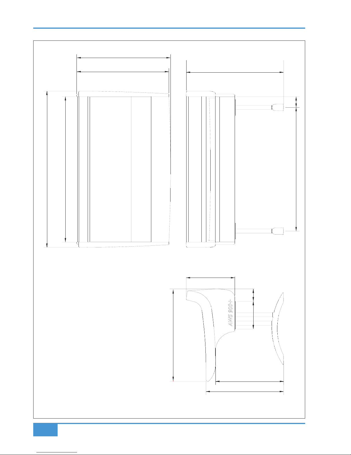
The AWS 900+ SE console is a self contained system; there are no remote power supplies or I/O racks. The
frame is not fitted with cooling fans. See the following page for a drawing of the console footprint.
Air Conditioning Requirements
It is unlikely that additional air conditioning will be required after installing the AWS 900+ SE (with its typical
450W dissipation). It is possible however, that when all the studio equipment is taken into consideration,
particularly if additional lighting is being installed, the combined heat output could be sufficient to cause the
temperature to rise to uncomfortable levels. The appendix section contains environmental specifications for SSL
equipment.
Cable Ducting
Cable ducting may be required between the console and any outboard racks and the recording areas. If a full
remote patchbay is being provided then the ducting will need to be of sufficient size to allow at least twelve 24circuit multicore cables to be accommodated.
Service Access
Access to all electronic assemblies within the frame is from the front of the console. Note however, that each of
the console’s modules is retained by a screw through its rear panel. Is necessary therefore, to have access to
the rear of the console.
Power Connections
The console is fitted with auto-sensing power supplies which will function at any voltage from 90 to 250 volts
without adjustment. It is supplied with two IEC mains power-leads. One will have a US-style 3-pin mains plug
fitted, the other will be unterminated to allow the user to install a mains plug of their preferred type; the wires are
colour-coded according to the EC standard.
Grounding
A standard system should not require any additional grounding over and above that provided by a correctly
installed mains supply. The console’s chassis is permanently bonded to mains earth.
Safety Warning: The mains input ground wire MUST be connected to the supply earth.
Thermal Considerations
The maximum dissipation of an AWS 900+ SE is less than 600W (typically 450W). The console is cooled by
convection from the front inlet (in the knee panels) to the exit at the top of the rear panels. It is very important
that these ventilation grills are not obstructed in any way.
Particular care must be taken when considering the installation of studio furniture – such as shelving – across
the rear of the console. Sufficient space must be left for the free flow of air from the rear grills, and also above
the heatsink fins. Clearance behind the console must not be less than 50mm and clearance above the console
not less than 200mm.
Note: The heatsink fins on the console rear panels can reach temperatures of approximately 30 degrees
Celsius above ambient room temperature.
AWS 900+ SE Owner’s Manual
3-1
Installation
Section 3 – Installation
Page 18
Installation
3-2
AWS 900+ SE Owner’s Manual
863
8
6
2
8
7
7
6
3
7
7
2
6
4
5
4
260 115
9
1
0
102
1154
1458
1358
Page 19

Unpacking The Console
The AWS 900+ SE is supplied in a wooden crate with the legs in a smaller separate crate.
Using a large screwdriver or pry-bar carefully open the crate containing the console. The crate is not designed to
be reusable so does not have to be removed intact . With the crate sides removed there will be sufficient space for
f
our people to lift the console clear from the base of the crate.
Note: The console is shipped with its trim fitted, avoid using the trim as a lifting point.
Do not lift the front of the console by using the buffer alone.
Attaching the legs
Again, it is recommended that four people are available to perform this operation
The bolts required to attach the legs are shipped in the same crate as the legs. A 6mm hex-key is provided as one
of the tools included in the AWS 900+ SE console crate.
The console should first be rolled onto its back. Ensure that ample padding is provided – such as blankets or
bubble-wrap – to support the rear panels (the PSU heatsink fins protrude from the rear of the console, and care
must be taken not to damage them).
Position the legs on the console beam and attach the M10 bolts using the 6mm hex-key supplied. There are four
bolts per leg.
Using four people, the console may now be tipped forward onto its feet. When the console is in position, the feet
can be slightly adjusted to compensate for an uneven floor. Do not unscrew the feet by more than 15mm.
AWS 900+ SE Owner’s Manual
3-3
Installation
Page 20
Installation
3-4
AWS 900+ SE Owner’s Manual
Page 21

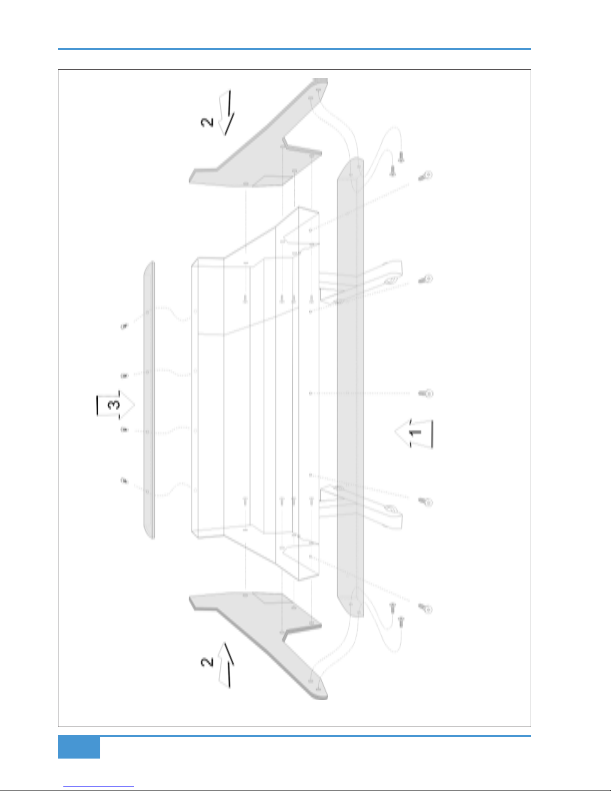
Removing the trim
If it is necessary t o remove the trim panels – to adjoin existing furniture – then please refer to the following
information and the illustration shown on the facing page.
Note that it is not necessary to remove any of the audio modules to gain access to the trim fixing screws.
Front Buffer
T
he front buffer is secured by nine pan-head screws – five in the front beam and two in each end trim. These are
all visible from beneath the buffer.
End Trim
Each of the end trims is secured by four countersunk Posi-head screws through the profile (one is located in the
kneepanel area, two more are found either side of the main beam and the fourth is located on the bottom corner
of the outside profile), as well as two pan-head screws through the front buffer (visible from beneath the buffer).
Top Trim
The top trim is clipped over the front of the meter panels and secured onto the back panels by four M3 screws.
AWS 900+ SE Owner’s Manual
3-5
Installation
Page 22

Installation
3-6
AWS 900+ SE Owner’s Manual
Solid State Logic
Drg. No:
22/03/06
AWS 900+
SD/GC
Connector Panel
© Solid State Logic
657X2 657X1 656X2 656X1 655X2 655X1 654 653 652 651
EXT A3 EXTA4
EXT A1 EXTA2
Send - Insert - Rtn
Meter Out Ext B 1-4
Mini
AR
Mini
AL
Listen
Mic In
T/Back
Mic In
Listen
Mic Out
T/Back
Mic Out
Desk Mic
Gain
Ext TB
Mic Gain
Osc
Out
Mini
BR
Mini
BL
MON B MON A
Send
Left
Return
Left
Send
Right
Return
Right
Left
Out
Right
Out
Left
Out
Right
Out
Send
Left
Return
Left
Send
Right
Return
Right
MIX OUTPUTREC OUTPUT
Key
In
Echo
Rtn 1L
Echo
Rtn 1R
FX1
Out
FB AL
Out
FB AR
Out
Key
In
Echo
Rtn 2L
Echo
Rtn 2R
FX2
Out
FB BL
Out
FB BR
Out
Echo
Rtn 3L
Echo
Rtn 3R
FX3
Out
Echo
Rtn 4L
Echo
Rtn 4R
FX4
Out
8 Track
Bus Out
Cue/FX
Bus Out
641
DIR
LINE
MIC
RTN
SEND
INST
1.4
TRS Jack.
Instrument and Footswitch inputs Tip = Hot, Sleeve = screen
All other jacks Tip = Hot, Ring = Cold, Sleeve = screen
XLR Male
Pin 2 = Hot
Pin 3 = Cold
Pin 1 = Screen
XLR Female
Pin 2 = Hot
Pin 3 = Cold
Pin 1 = Screen
Red Light/Talkback/GPI/O
Connector Type: 25-way D-type female
Pin Ribbon pin Description Notes
1 5 Red Light Relay contact A Normally open
14 6 Red Light Relay contact B Follows Red Light switch
2 7 0V
15 8 GP Input 1 (not used)
3 9 GP Input 2 (not used)
16 10 Monitor Cut Forces Cut when active
4 11 Monitor Dim Forces Dim when active
17 12 Slate switch
5 13 Listen switch
18 14 Red Light switch
6 15 TB All switch
19 16 FB A switch
7 17 FB B switch
20 18 Ext TB switch
8 19 +4V Max current 200mA(fused)
21 20 Slate Tally
9 21 Listen Tally
22 22 Red Light Tally
10 23 TB All Tally
23 24 FB A Tally
11 25 FB B Tally
24 26 Ext TB Tally
12 27 n/c
25 28 n/c
13 29 n/c
All inputs are active low (ie connect to 0V to activate). Inputs are pulled up to +4V via 3K9 resistor
Inputs are diode clamped to 0V and +4V to protect the console circuitry
All tallies are open collector with 47R series resistor.
AWS Connector Panel Layout
RED LIGHT/TALKBACK/GPIO
1 - FOOTSWITCH - 2
AWS Audio 25wD pinouts
cct Hot Cold Screen EXT A Inputs 1-4 Meter Out Ext B Inputs Mon Insert Send Mon Insert Return Mon A MonB 8 Track Out Cue/FX Out
1 24 12 25 Left Left 1 Left Left Left Main Left Alt Left Bus 1 Cue AL
2 10 23 11 Right Right 1 Right Right Right Main Right Alt Right Bus 2 Cue AR
3 21 9 22 Centre Centre 2 Left Centre Centre Main Centre Alt Centre Bus 3 Cue BL
4 7 20 8 LFE LFE 2 Right LFE LFE Main LFE Alt LFE Bus 4 Cue BR
5 18 6 19 Left Surround Left Surround 3 Left Left Surround Left Surround Main Left Surround Alt Left Surround Bus 5 FX1
6 4 17 5 Right Surround Right Surround 3 Right Right Surround Right Surround Main Right Surround Alt Right Surround Bus 6 FX2
7 15 3 16 n/c Solo Left 4 Left Lt to Decoder Lt From Encoder Mini AL Mini BL Bus 7 FX3
8 1 14 2 n/c Solo Right 4 Right Rt to Decoder Rt from Encoder MiniAR Mini BR Bus 8 FX4
CENTRE SECTION CHANNELS 1-24
4 x MIDI IN/THRU/OUT
BEHIND CHANNELS 5-12
Connector Type: 25-way D-type female
Rev:
Date:
Design:
Drawn:
Ref:
Page 23

Studio Integration
Audio Connections
All connections to the AWS 900+ SE, with the exception of the two headphone jacks, are found on the lower rear
p
anels of the console. The headphone sockets are located on the centre-section knee panel.
The console rear panel carries a label which identifies all the connections on the connector panel, and provides
the pinout for each one (see facing page). This information is also provided in the Appendices section of this
manual.
Line Level Input/Outputs
All other analogue inputs and outputs can be connected via a patchbay. It is recommended that the cable shield is
connected at the console end and disconnected at the patch row to avoid ground loops. Wiring to the installation
should normally have the shield connected to the patch row. The shield connection of all jacks should be linked
together (note that patch rows with solid metal front panels will automatically do this) and then linked to a common star
point on the patchbay. This starpoint can then be returned – via a thick grounding cable (6mm sq. or greater) – to the
chassis stud on the rear of the AWS 900+ SE console. This will reduce the risk of earth loops within the installation.
Note that the shields of all analogue inputs and outputs other than the microphone inputs are connected directly
to the chassis of the AWS900+.
AWS 900+ SE Owner’s Manual
3-7
Installation
Page 24
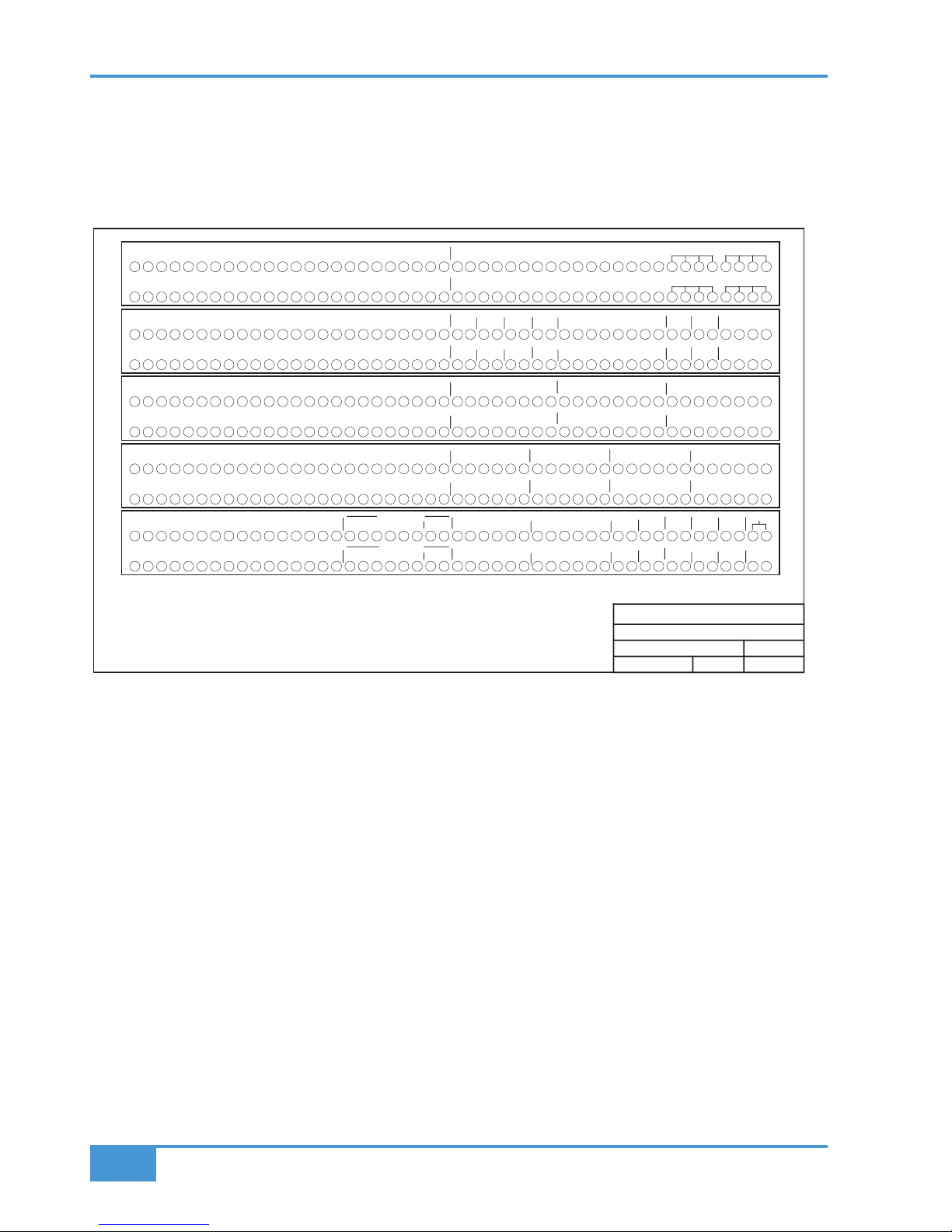
Connecting a Patchbay
The AWS 900+ SE may, of course, be fully or partially integrated to an external patchbay. 3rd party options are
available, and SSL can provide patchbay solutions as cost options – contact your local SSL distributor for further
information.
A
n example patch layout for the centre section and channels is provided below:
When constructing patchbays, the following guidelines may be useful.
Mic Inputs
If Mic inputs are being connected to a patchbay, then the patch jacks should be insulated from the main body of
the patchrow. There are commercially available patchrows that meet this requirement. The ground connection from
each microphone must be taken through the patch jacks to the XLR on the back of the console without interruption.
Instrument Inputs
It is not recommended that the ‘Instrument’ inputs are broken out to a pat chbay. These inputs are unbalanced, and
the cable lengths should be kept at short as possible.
241 2 3 4 5 6 7 8 9 10 11 12 13 14 15 16 17 18 19 20 21 22 23 25 26 27 28 29 30 31 32 33 34 35 36 37 38 39 40 41 42 43 44 45 46 47 48
241 2 3 4 5 6 7 8 9 10 11 12 13 14 15 16 17 18 19 20 21 22 23 25 26 27 28 29 30 31 32 33 34 35 36 37 38 39 40 41 42 43 44 45 46 47 48
241 2 3 4 5 6 7 8 9 10 11 12 13 14 15 16 17 18 19 20 21 22 23 25 26 27 28 29 30 31 32 33 34 35 36 37 38 39 40 41 42 43 44 45 46 47 48
241 2 3 4 5 6 7 8 9 10 11 12 13 14 15 16 17 18 19 20 21 22 23 25 26 27 28 29 30 31 32 33 34 35 36 37 38 39 40 41 42 43 44 45 46 47 48
241 2 3 4 5 6 7 8 9 10 11 12 13 14 15 16 17 18 19 20 21 22 23 25 26 27 28 29 30 31 32 33 34 35 36 37 38 39 40 41 42 43 44 45 46 47 48
241 2 3 4 5 6 7 8 9 10 11 12 13 14 15 16 17 18 19 20 21 22 23 25 26 27 28 29 30 31 32 33 34 35 36 37 38 39 40 41 42 43 44 45 46 47 48
1 2 3 4 5 6 7 8 9 2410 11 12 13 14 15 16 17 18 19 20 21 22 23
1 2 3 4 5 6 7 8 9 2410 11 12 13 14 15 16 17 18 19 20 21 22 23
1 2 3 4 5 6 7 8 9 2410 11 12 13 14 15 16 17 18 19 20 21 22 23
1 2 3 4 5 6 7 8 9 2410 11 12 13 14 15 16 17 18 19 20 21 22 23
1
2 3 4 5 6 7 8 9 10 11 12 13 14 15 16
241 2 3 4 5 6 7 8 9 10 11 12 13 14 15 16 17 18 19 20 21 22 23 25 26 27 28 29 30 31 32 33 34 35 36 37 38 39 40 41 42 43 44 45 46 47 48
241 2 3 4 5 6 7 8 9 10 11 12 13 14 15 16 17 18 19 20 21 22 23 25 26 27 28 29 30 31 32 33 34 35 36 37 38 39 40 41 42 43 44 45 46 47 48
241 2 3 4 5 6 7 8 9 10 11 12 13 14 15 16 17 18 19 20 21 22 23 25 26 27 28 29 30 31 32 33 34 35 36 37 38 39 40 41 42 43 44 45 46 47 48
241 2 3 4 5 6 7 8 9 10 11 12 13 14 15 16 17 18 19 20 21 22 23 25 26 27 28 29 30 31 32 33 34 35 36 37 38 39 40 41 42 43 44 45 46 47 48
1 2 3 4 5 6 7 8 9 2410 11 12 13 14 15 16 17 18 19 20 21 22 23
1 2 3 4 5 6 7 8 9 2410 11 12 13 14 15 16 17 18 19 20 21 22 23
MAIN LS A MINI B
LRL
R C LFE LS RS
MAIN LS B
L
R C LFE LS RS
MINI A
LR
AMP IN AMP
L RL
R C LFE LS RS
AMP IN
L
R C LFE LS RS
AMP
L
R
F/B A
OUT
F/B B
OUT
AMPALRA
MPB
LR
REC
OUT
REC
INSERT
LR
RTN
LR
1 2 3 4 5 6 7 8 9 2410 11 12 13 14 15 16 17 18 19 20 21 22 23
1L 1R 2L 2R 3L 3R 4L 4R
ECHO RETURN IN
FX OUT
1
L 1R 2L 2R 3L 3R 4L 4R
EXT A 6 TR 1
LCR LS RSLFE
EXT A 6 TR 4
LCR LS RSLFE
EXT A 6 TR 2
LCR LS RSLFE
EXT A 6 TR 3
LCR LS RSLFE
6 TRACK REPLAY 1
L
CR LS RSLFE
6 TRACK REPLAY 4
L
CR LS RSLFE
6 TRACK REPLAY 2 6 TRA CK REPLAY 3
L
CRLSRSLFE
123456
1L 1R 2L 2R 3L 3R 4L 4R
EXT B IN
3L 3R 4L 4R
STEREO REPLAY
1L 1R 2L 2R
12
KEY IN
1 2 3 4 5 6 7 8 9 10 11 12 13 14 15 16
1 2 3 4 5 6 7 8 9 10 11 12 13 14 15 16
LR LR LR LR
MON INS RTN
L
R C LFE LS RS
L
R C LFE LS RS
Lt Rt
Lt Rt
MON INS SEND
DECODER
ENCODER
1.0
Solid State Logic
AWS900 + Standard Patch Layout
SD/GC
C
D
E
F
DIRECT OUTPUTS
G
H
C
D
E
F
H
CHANNEL LINE INPUTS
CHANNEL INSERT SENDS
CHANNEL INSERT RETURNS
2417 18 19 20 21 22 23
AWS900+
17/07/06TAWSPA.71
Title:
Revision:
C
onsole:
Sheet: Date:
Drawn by:
J
K
J
K
DAW INPUTS
MIC LINES
A
B
A
B
MIC INPUTS
DAW OUTPUTS
MIX
OUT
MIX
INSERT
LR
R
TN
L R
TRACK BUS OUT
12345678
12345678
Notes:
1. Patchrow AB is an isolated patchrow.
2. D31 is linked to C33, 35, 37, 39
D32 is linked to C34, 36, 38, 40
3. J47 and J48 are linked
4. Parallel A41-44, A45-48, B41-44, B45-48
Normalling Information:
All patchpoints are half normalled unless otherwise stated below.
A1-24 are fully normalled to B1-24.
A25-48 are not normalled to B25-48
J1-16 are not normalled to K1-16.
J23,24 are not normalled to K23-24.
J46-48 are not normalled to K46-48.
G
341 2L R
CUE B FX SENDS
LR
CUE A
FX IN
341 2L RR
ROW ROW
LTN
IN
LST
OUT
OSC
TB
IN
LST
MIC
1L 1R 2L 2R 3L 3R 4L 4R
STEREO RECORD IN
MIX DISTRIBUTION OUT
25 26 27 28 29 30 31 32 33 34 35 36 37 38 39 40
25 26 27 28 29 30 31 32 33 34 35 36 37 38 39 40
USER OPTION
USER OPTION
USER OPTION
USER OPTION
L
FX INFX IN
RECORDER IN
DIST
Installation
3-8
AWS 900+ SE Owner’s Manual
Page 25

DAW Connection
The AWS 900+ SE console communicates with a DAW directly via Ethernet or via three MIDI ports. To use the
Ethernet option a thi rd party ipMIDI software driver must be installed on the DAW computer. Which Using these
m
ethods of communication allows the AWS 900+ SE t o be used with a wide variety of DAW applications on a wide
variety of platforms. The AWS 900+ SE uses Mackie control or a ‘HUI’ compatible protocol, and so any DAW
program that can be configured to use three HUI devices can access the full power of the AWS 900+ SE.
Please refer to your DAW manual for details on how to configure the DAW application for AWS 900+ SE under
M
ackie or HUI control.
Overview
In normal operation the AWS uses an Ethernet connection for DAW control and the SSL AWS900 Remote for
session management. The next section describes how to download and install the ipMIDI driver and AWS 900
Remote on Macintosh and PC.
Optionally the AWS 900 can use a standard MIDI connection between the AWS 900+ SE console and your DAW
using a multi port MIDI interface. In this mode only one DAW layer can be configured. The console communicates
with the DAW via the MIDI ports located on the rear of the console: Details are provided at the end of this section.
Installing the ipMIDI driver and Logictivity browser
Download on to your workstation computer etiher the AWS900SE_Mac_Support.dmg disk image (Macintosh) or
the AWS900SE_Win_Support.zip file (windows). These contain the AWS 900 Remote and ipMIDI applications and
the latest version of the installation instructions:
http://www.solidstatelogic.com/support/consoles/aws900+/downloads.asp
System Requirements for your workstation computer: AWS Remote is a Java application. It will run under Java
Version 5 or higher. ipMIDI is compatible with Windows 2000 (maximum 9 MIDI ports), XP and Vista and Macintosh
OSX 10.4 and OSX 10.5.
Software Installation (Macintosh)
Mount the AWS900SE_Mac_Support.dmg disk image and open it.
AWS Remote: Drag the enclosed AWS Remote application to the Applications folder, then to the Dock or any other
convenient location.
ipMIDI: Double click on the ipMIDI.pkg file to run the installation program. Note that you will be asked to log out
and in again once you have completed t he installation. Once you have logged back in open Audio MIDI Setup and
double click on the ipMIDI icon. Set the number of MIDI ports to 10 in the resulting pop-up.
If you are upgrading an older copy of ipMIDI you must uninstall it before running the installer. To uninstall ipMIDI
simply delete: </Library/Audio/MIDI Drivers/ipMIDIDriver.bundle>. You should empty the Trash after deleting the
bundle file before running the installer.
AWS 900+ SE Owner’s Manual
3-9
Installation
Page 26
S
oftware Installation (PC)
Open the AWS900SE_Win_Support.zip archive.
AWS Remote: Copy the AWSRemote.exe file to the Program Files folder (or any other convenient location) then
create a shortcut to it on your desktop and/or task bar. Double clicking on this will launch the AWS 900 Remote
p
rogram.
ipMIDI: Run the setupipmidi_1.6.exe application (note that the last part of the name may change depending on the
version you are installing) by double clicking on it. Note that you will have to restart the computer at the end of the
setup process. Once the computer has restarted right click on the ipMIDI icon in the task bar and set the number
o
f MIDI ports to 10 in the resulting pop-up.
If you are upgrading an older copy of ipMIDI you must uninstall it (using Add/Remove programs) before running
the installer.
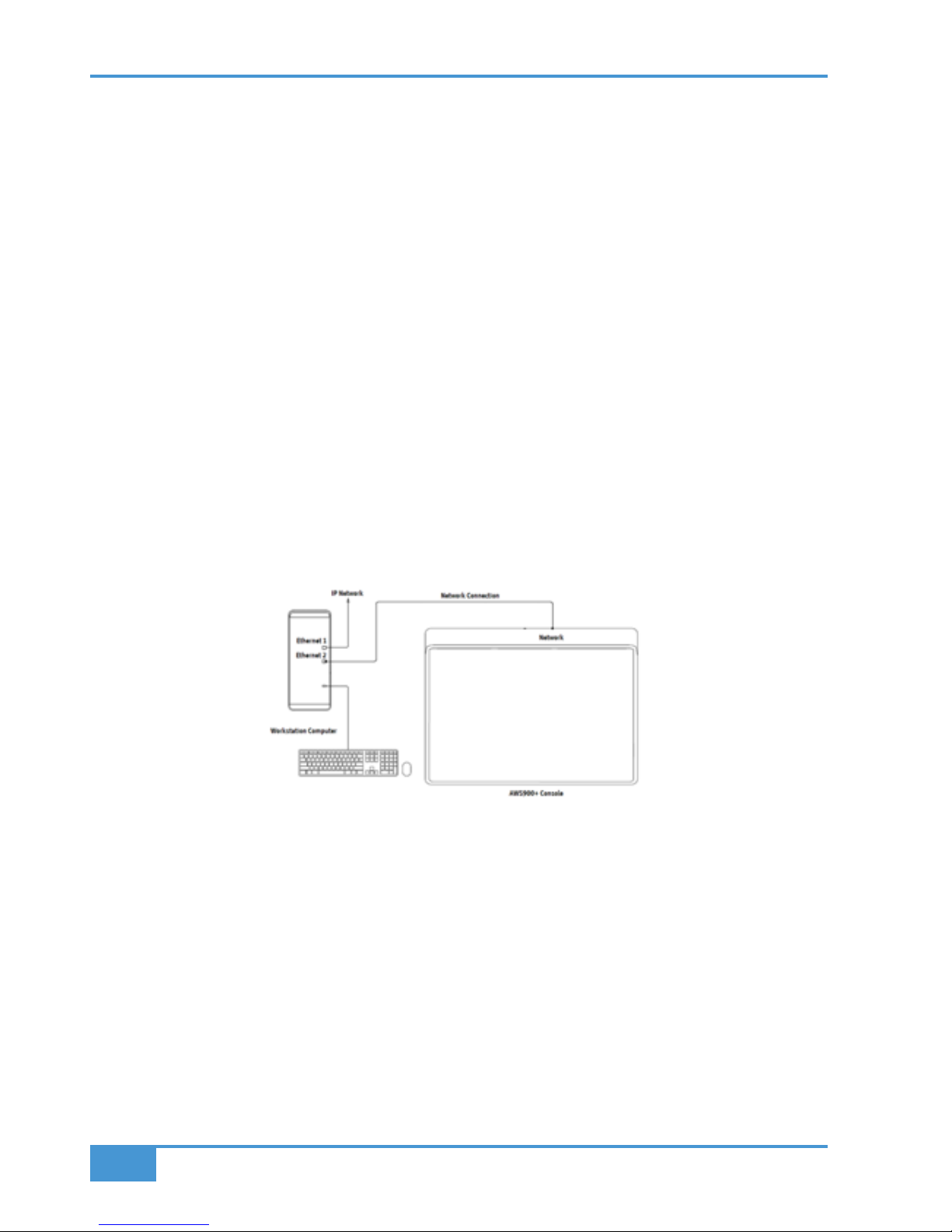
Make and configure the network connection
The AWS Logictivity software is designed to communicate with your workstation over Ethernet using the ipMIDI
driver to emulate a multiport MIDI interface. The ipMIDI driver enables your workstation to send and receive MIDI
control data via a network connection. Using Ethernet ensures the fastest possible communication between your
workstation computer and AWS. This network connection is essential if you wish to benefit from all of the new SE
features. The standard installation uses an RJ45 crossover network cable (not supplied) to connect the console’s
network connector directly to a separate network port on your workstation computer using the console’s default
fixed IP address of 192.168.1.2. Note that many computer adaptor cards will autosense a direct connection
negating the need for a crossover cable. If you are unsure whether your workstation computer’s network adapter
has this functionality, please use a crossover rather than a pin to pin cable.
It is possible to connect AWS to a larger network which incorporates multiple computers and to enable dynamic
(DHCP) addressing. These configurations need special consideration. Please see the notes at the end of these
instructions for details.
Direct Network Connection (Macintosh):
Please note that currently OS X does not allow two ports to be used for IP traffic. As such, the connection to your
main network will not be available while the AWS is connected.
To simplify the process of switching between networks, it is recommended that you create a new network Location
for the AWS900 in network preferences. Another Location (‘internet’ for example) could be created to enable
connection t o the internet. This would use the network settings provided by your Internet Service Provider or
network administrator. You can easily switch between network Locations by going to the Apple Menu and scrolling
down to Location.
Installation
3-10
AWS 900+ SE Owner’s Manual
Page 27
• Using an RJ45 cable, make a direct network connection between the network port on your AWS to a network
port on your workstation computer and check that the IP address is set to FIXED in the console’s
SSL > MISC > NET menu.
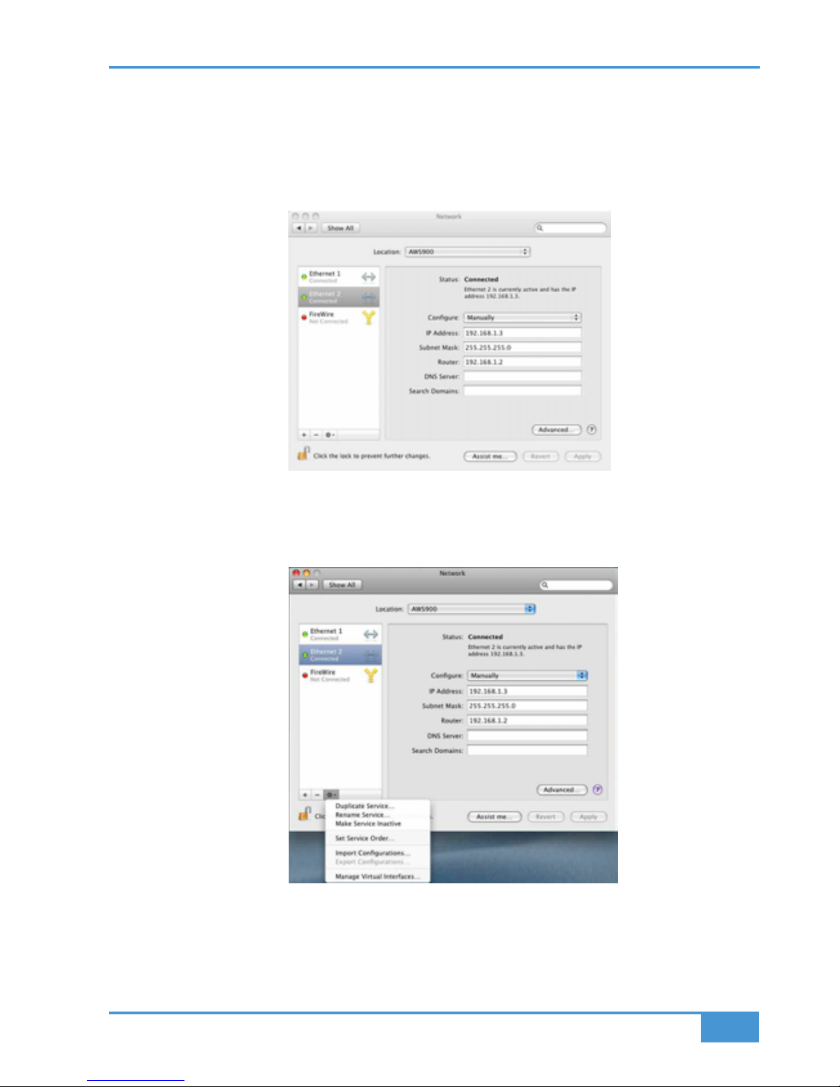
• Open System Preferences and click on Network. Create a new location by clicking where it says Location,
scroll down to Edit Locations and click the ‘+’ sign. Name the new location AWS900.
• Next, select the Ethernet port which is connected your AWS and configure as shown below:
• If your Macintosh features multiple network ports, you should set the priority of these so that the Ethernet
port connected to your AWS is at the top of the list. To do this, choose Set Service Order from the Actions
pop–up menu:
AWS 900+ SE Owner’s Manual
3-11
Installation
Page 28
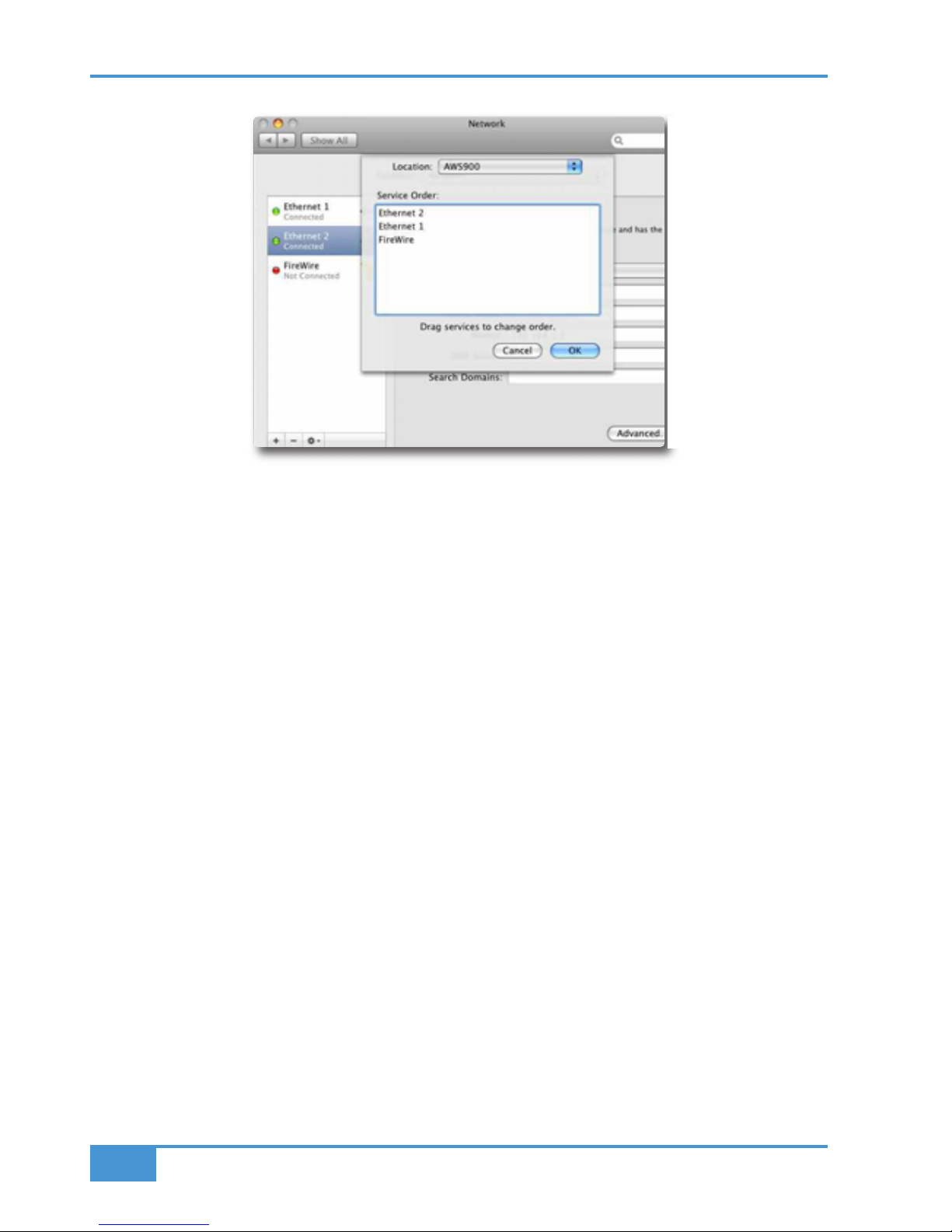
• Now drag the port connected to the AWS to the top of the list (in our example this port is Ethernet 2):
• Now click OK then Apply.
• Alternatively, if you have already created a separate Location for your existing network you can simply delete
the unused ports (Airport, Firewire) from the AWS900 location so that only the network port connected to
AWS is remaining.
Installation
3-12
AWS 900+ SE Owner’s Manual
Page 29
Direct Network connection (PC):
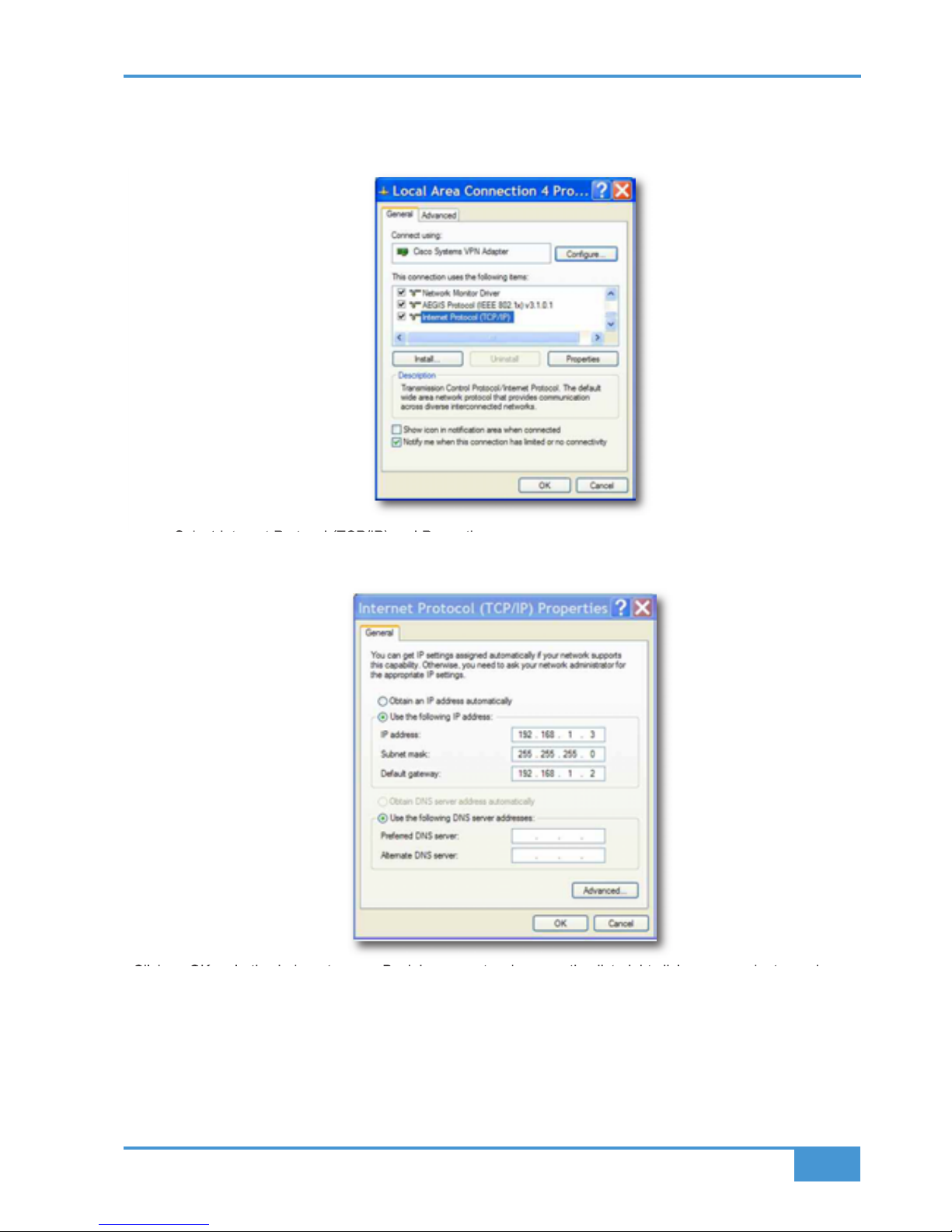
• Double click on Network Conn ect ions in Start/Control Panel. Right click on the network adapter connected
to your AWS (likely to be called "Local Area Connection"). Select Properties.
• Select Internet Protocol (TCP/IP) and Properties.
• Next, configure the adapter as shown below:
Click on OK on both windows to save. Back in your network connection list, right click on your adaptor and ensure
that it is enabled. If it is disabled, the enable option will appear in the list. Click on enable.
AWS 900+ SE Owner’s Manual
3-13
Installation
Page 30
Enabling ipMIDI on your AWS:
In the SSL > MISC > SETUP menu, toggle the ‘MIDI connects via: ’ setting to ‘Network’. Your console will now
communicate with your workstation via Ethernet. With ‘MIDI connects via:’ set to ‘MIDI ports, AWS will
communicate with your workstation via the conventional MIDI connectors on the rear of your console.
N
ote: You will need to reboot the console after changing this option.
Also in the SSL/MISC/SETUP menu, ensure that the ‘DAW’ option (workstation layer 1) and DAW2 (workstation
layer 2) are set to match your workstation or workstations if you are using the second layer. Please note that you
will need to restart the console after making a change to the DAW layer options.
Finding the console on the AWS Remote application:
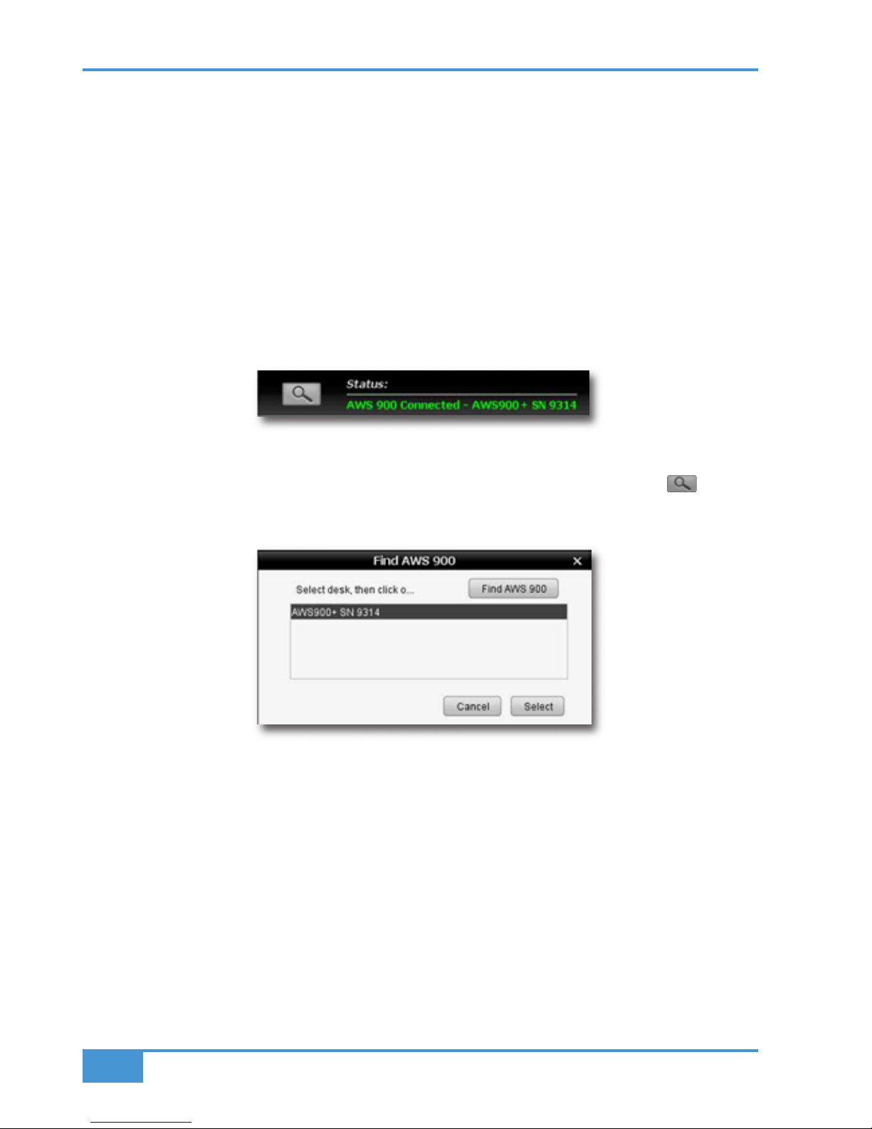
Launch AWS Remote on your workstation. If you only have one AWS console on the network, AWS Remote will
automatically locate the consol e and the message ‘AWS 900 Connected’ will be shown in green text in the bottom
left hand corner of the browser:
If you have multiple AWS consoles on the network or the AWS Remote browser did not automatically l ocat e your
console ‘No AWS 900 connected’ will be shown in red text. In this instance, click on the find icon . If the list
is empty, click on find AWS900, select the console you wish to connect to and click on select.
If your console does not appear in the list, it suggests you have a network related issue. Please follow the steps
in the network trouble shooting section at the end of this document to resolve the issue.
Installation
3-14
AWS 900+ SE Owner’s Manual
Page 31

Setting your workstation(s) to communicate via ipMIDI
The AWS 900+ SE software uses 10 virtual MIDI ports which are pre-assigned as follows:
* Note that MIDI port 4 or ipMiDI port 7 can be used for MTC input, allowing MTC to be connected from systems
(such as RADAR) that do not support the ipMIDI driver. MTC should only be routed to one port at a time.
Note that there are now two switchable workstation layers allowing to independent workstations to be interfaced.
Once configured, you can switch between the two layers using the console’s SSL>DAW menu. Port 7: If your
console is equipped with AWSomation, this port is used to feed AWSomation with MTC.
Port 8: Used for the import and export of legacy SysEx TR and AWSomation data.
Port 9-10: Mapped to the conventional MIDI connectors on the rear of the console allowing connection of a
keyboard or other MIDI device to your DAW via ipMIDI .
To select which DAW is assigned to each layer go to SSL>MISC>SETUP on your console and select the following:
DAW 1: select from Protools HUI / Logic / Logic Handshake / Nuendo / Digital Perfomer / Sonar
DAW 2: select from Protools HUI / Logic / Logic Handshake / Nuendo / Digital Perfomer / Sonar / None
After making these changes the console should be restarted.
The MCU protocol suports automatic detection of connected control surface s. To enable this select
Logic Handshake. Logic will then automatically detect the AWS. If you select Logic Handshake on both layers
then Logic will detect 6 control surfaces, which may not be what you want! The other protocols do not transmit
handshaking messages.
To enable control of your workstation via HUI or MCU your workstation(s) must be configured to match the
appropriate layer in the list above. This is done using the MIDI Controller configuration page of your workstation.
The following pages show examples using Pro Tools 7 and Logic Pro 8.
Port Layer Assignment Port Layer Assignment
1 1 Faders 1–8 9 – AWS Midi port 1
2 1 Faders 9–16 10 – AWS Midi port 2
3 1 Faders 17–24
4 2 Faders 1–8
5 2 Faders 9–16
6 2 Faders 17–24
7 – MTC input *
8 – SysEx
AWS 900+ SE Owner’s Manual
3-15
Installation
Page 32

P
ro Tools 7
In the Setup menu, click on Peripherals and select the MIDI Controllers tab. Using MIDI controllers 1, 2 and 3,
select HUI as the MIDI controller Type and assign the MIDI ports for this layer’s DAW to the two MIDI controllers,
as listed in the table above. If Pro Tools has been assigned to Layer 1, the MIDI Controllers window should look
like this:
If you have AWSomation, set the MTC generator port in the Synchronization tab to ipMIDI port 7 (or AWS MIDI port
4 if you are using the console MIDI ports):
Also, set the MMC midi port in the Machine Control tab to ipMIDI port 7 (or AWS MIDI port 4 if you are using the
console MIDI ports):
Installation
3-16
AWS 900+ SE Owner’s Manual
Page 33

L
ogic Pro 8
When Logic is assigned to one of the two AWS workstat ion layers a Mackie Control together with a Mackie Control
Extender must be added to the Logic Pro Preferences/Control Surfaces Setup menu as shown below:
AWS Faders 1-8 are mapped to the Mackie Control ports along with the Master Fader and workstation Cont rol
function switches. AWS Faders 9 -16 and 17-24 are mapped to the Mackie Control Extender ports. The actual
ipMIDI ports used will depend on which layer (or layers) Logic is assigned to. See the list of AWS MIDI port
assignments for details. It is essential that the layout shown is followed. If the physical arrangement is reversed,
then the AWS faders will not map correctly to the on-screen faders in Logic.
If the protocol is set to Logic Handshake, Logic should automatically detect the three virtual controllers which will
be shown in the Logic Setup menu (as shown above), with the appropriate AWS ipMIDI ports assigned. If Logic
fails to detect the control surfaces, then the controllers can be added manually via the New/Install menu and the
appropriate MIDI Out port and Input assigned. As described above, normally only one layer should be set to Logic
Handshake.
Full details can be found in the online Logic Pro 8 Control Surfaces Support guide in the Logic Help Menu.
AWS 900+ SE Owner’s Manual
3-17
Installation
Page 34

Note: Logic’s Click and ports environment layer selects the SUM of all of t he ipMIDI unpu t ports as its default MCU
control data source. This may lead to difficulties when using multiple DAW layers. To avoid Logic responding to
MIDI messages intended for the other DAW layer, the Click and Port MIDI port mapping should be changed from
S
UM to individual direct MIDI port assignment. The example below shows Logic on DAW layer 1:
Preferences/Control Surfaces Setup menu:
If you have AWSomation, set the MMC midi port in File/Project Settings/Synchronisation/MIDI to ipMIDI port 7 (or
AWS MIDI port 4 if you are using t he console MIDI ports):
For other DAWs, please refer to the program’s manual for details about configuring MIDI controllers.
Installation
3-18
AWS 900+ SE Owner’s Manual
Page 35

Network trouble shooting:
Most Ethernet adaptor cards have two leds associated with each port. The first indicates that the link is connected
and the second indicates network traffic. Please note that some Macintosh computers do not have external leds
to indicate status. Instead the link status is shown in the System Preferences/Network menu.
O
n your host workstation computer, confirm that the link led is permanently illuminated. If it is not permanently
illuminated, it suggests you have a cabling error. In this instance please check the following:
• The RJ45 network connector on the console and on your workstation are fully insert ed.
•
If you are using a pin-pin cable to make a direct connection between your console and workstation, try
replacing it with a crossover cable
• Try replacing the network cable
• If you are not using a direct connection between your console and workstation using the default fixed IP
address on the console, please try this simple configuration to rule out issues with external routers and
network switches. If the link led is illuminated, the next step is to confirm that the activity led is illuminating
periodically to show network traffic. If it does not illuminate periodically check the following:
• If your workstation is not connected directly to your console using a crossover RJ45 cable and fixed IP
addressing, follow the installation instructions to configure this simple netwo rk configuration to rule out
issues with any external routers or network switches.
• Using the fixed default IP address on the console, check that the workstation has basic communications
using ‘ping’.
On Windows: Select Run under the Start menu. In the resulting window enter cmd to launch the command
prompt. In the command prompt window enter ping 192.168.1.2
On OSX: Open a Finder window, select Applications, then Utilities, and double-click on Terminal. In the
terminal window enter ping –c4 192.168.1.2
In both cases your host computer will try to establish communications with your console. In the
resultant terminal text, check that the console responded to every message sent by your workstation.
AWS 900+ SE Owner’s Manual
3-19
Installation
Page 36

Larger networks:
To ensure minimum latency the ipMIDI driver uses multicast UDP rather than TCP/IP. This means that:
• The network connection should be as short as possible and should only use routers that can support high
data transfer rates. Problems have been experienced with some domestic routers, particularly when used
with Pro Tools.
• Because ipMIDI uses multicast UDP packets, messages between one computer and AWS900+ SE will be
received by all other computers on the network, potent iall y causing problems in installations with more than
one AWS900+ SE. The UDP packets can be blocked by using a firewall rout er and connecting the main
network to the WAN connector. The firewall can then be configured to allow all traffic apart from UDP ports
21928 through 21947 which are used by ipMI DI and (optionally) port 50081 which is used by the AWS900+
SE Remote application. Note that it may be necessary to use a separate Ethernet switch in place of the
integrated firewall router switch, as some of these can not support the high data transfer rate required. The
NetGear FS108 (an eight port switch) has been used successfully. Most systems can be easily configured
with a direct connection between AWS900+ SE and the controlling computer.
Installation
3-20
AWS 900+ SE Owner’s Manual
Page 37

A
ssigning the AWS900+ SE IP Address:
By default, AWS900+ SE uses a fixed IP address of 192.168.1.2. Dynamic (DHCP) address can be selected via
the SSL > MISC > NET menu. The currently assigned address is also shown in the MISC > ABOUT > NET menu.
If your AWS900+ SE is connected to the computer via a network switch or router, it should be assigned a DHCP
IP address; otherwise the fixed option should be used. Once you have altered the IP mode, you need to restart
y
our AWS for the change to take effect. A software restart option is available in the SSL > MISC > NET menu.
An alternative fixed IP address can be set using the console diagnostic port. This should not be necessary in most
installations. You will need a PC or Mac running terminal emulator software. Connect your computer’s serial port
to the rear of the console using a 9 way ‘D’ type extension cable. The pin out for the console’s 9 way ‘D’ type serial
connector is shown below:
Set the terminal as follows: Baud rate 19200, 8 data bits, No parity, No start bit, 1 stop bit, Flow control Xon/Xoff
Press the ‘Return’ key (<CR>) and the terminal window should echo a ‘>’ if communication is established. To fix
the IP address type the following:
ip <CR>
setip nnn nnn nnn nnn <CR> where ‘nnn...’ is the IP address, 192.168.1.2
setmask nnn nnn nnn nnn <CR> where ‘nnn...’ is the subnet mask 192.168.1.1. Note that this should match other
devices local to the console.
setgate nnn nnn nnn nnn <CR> where ‘nnn...’ is the gateway address e.g. ‘10 1 1 1’
Pin Description
1 Carrier (linked to 0V)
2 Tx
3 Rx
4 DTR (linked to DSR)
5 0V
6 DSR (linked to DTR)
7 RTS (linked to CTS)
8 CTS (linked to RTS)
9 RI (linked to 0V
AWS 900+ SE Owner’s Manual
3-21
Installation
Page 38

Enabling the AWS Logictivity features on your console
NOTE: The following only applies to AWS consoles that currently do not have AWS SE software.
1) F ind the console’s serial number. The serial number label is located on the rear of the console adjacent to the
mains inlet connector. The serial number starts with the letters AWS followed by a numerical number. Make a note
of the numerical number for the registration process (e.g. if the serial number is AWS293, not e 293).
2) If you have not registered your console on-line (or you have forgotten your username), complete the on-line
r
egistration:
http://web.solidstatelogic.com/update/newuser.jsp
3) Navigate to the on-line registration page and enter your activation code and the numerical element of your
console’s serial number previously noted. The activation code can only be used once. Please ensure that you enter
the correct serial number:
http://web.solidstatelogic.com/update/activateacode.jsp
4) After a successful activation, you will be invited to download and install the latest version of software. Follow the
link to the download page.
Using Physical MIDI Ports to Connect your DAW
Optionally the AWS 900 can use a standard MIDI connection between the AWS 900+ SE console and your DAW
using a multi port MIDI int er f ace. In this mode only one DAW layer can be configured. To select this mode navigate
to the SSL/Misc/Setup menu and set MIDI communicates via: MIDI Ports.
The console communicates with the DAW via the MIDI ports located on the rear of the console:
MIDI ports should be connected to your DAW MIDI interface unit – three available ports are required (one port
includes an IN and OUT socket). To connect a port, the output of the MIDI interface unit port 1 should connect to
the MIDI 1 input port of the AWS 900+ SE and the MIDI output of the AWS 900+ SE port 1 should connect to the
input of your MIDI interface unit port 1. Repeat for the other ports using the diagram above as a guide. Port 4 is
used both for archiving Total Recall and Automation data and to receive MIDI Timecode (MTC).
Follow the instructions on configuring your workstation but use the physical MIDI ports rather than the virtual MIDI
ports when selecting MIDI ports.
Note that ports 5 and 6 are currently not implemented and are reserved for future expansion.
Please note that the recommended maximum length of MIDI cables is 15 meters.
IN OUT IN OUT IN OUT IN OUT IN OUT IN OUT
MIDI 1 MIDI 2 MIDI 3 MIDI 4 MIDI 5 MIDI 6
IN OUT IN OUT IN OUT IN OUT IN OUT IN OUT
Installation
3-22
AWS 900+ SE Owner’s Manual
Page 39

AWS 900+ SE Owner’s Manual
4-1
Section 4 – Console Operator’s Guide
Overview
The AWS 900+ SE is a powerful combination of analogue console and workstation controller from Solid State
Logic. It draws on many years of design experience, and incorporates many features from SSL’s world famous
m
usic consoles.
The AWS 900+ SE uses SuperAnalogue™ technology from SSL’s flagship music console, the XL 9000 K Series.
The AWS 900+ SE retains all of its sonic benefits and maintains a control surface that will be familiar to any
recording engineer who has previously used our 4000 or 9000 range of analogue audio consoles.
The rise of the DAW (Digital Audio Workstation) has brought many benefits to the audio production environment,
including electronic editing, integrated digital effects processing and session storage and recall.
However, the same problems of integration that have always existed still exist within the studio environment
today. A studio requires either 5.1 or stereo monitoring in order to accurately monitor audio signals. The DAW
will have no faders or tactile controls with which to operate its myriad of functions, so a comprehensive control
surface is required. High quality microphone pre-amplifiers will be needed to capture real sounds with the
highest possible signal integrity for high bandwidth DAW recorders operating at 192kHz. equalization and
dynamics are required in the analogue domain by many users who still consider analogue the benchmark to
which all digital processing is compared. Meters are required to view both input/output signals and recorded
signal levels for all audio paths.
The AWS 900+ SE console has been carefully designed with all of these essential studio requirements in mind.
It addresses all the needs of the current DAW environment in an integrated, high quality and robust design with
all of the sonic benefits expected from a Solid State Logic SuperAnalogue™ console.
Years of design experience have been utilised to create the ultimate capture path for up to 24 simultaneous
input paths into the DAW, where recorded signals can be edited, processed and mixed via the AWS 900+ SE
control surface. The signal paths can then be either summed internally within the DAW or returned to the
analogue domain for processing through the 24 SSL EQ sections and associated assignable dynamics
processors. Combined with a comprehensive 5.1 monitoring section, audio can be auditioned with complete
assurance that the fully balanced signal path throughout the console is of the highest possible audio integrity.
A high resolution digitally controlled gain element in each channel allows the 24 motorized faders to be switched
to control any DAW that supports the HUI or Mackie control protocols while retaining the analogue signal path.
The 24 faders and the 24 associated Channel Rotary Encoders provide direct control of DAW faders, pans,
sends, input and output routing. The Master Control Panel and the in-board screen give paged control of all
plug-in parameters under the HUI protocol.
In summary, the AWS 900+ SE is a Total Studio Solution for modern DAW based production environments.
About This Section
This section comprises two main parts. First there is an overview of how your DAW and the AWS 900+ SE can
be used together. Following this is a description of the function of each part of the console. The use of the DAW
controller section is covered in Section 5.
Console Operator’s Guide
Page 40

Direct Outputs
DIRECT
PRE/EFX
INST
MIC
LINE
auto
10
5
0
5
10
20
30
40
50
FLIP
L R
PAN
1 2 3 4
5 6 7 8
POST
Channel Module
Rear Connector
Panel
TRACK BUS
TRACK BUSS OUTPUTS
MIX BUS OUTPUTS
RECORD BUS OUTPUTS
PAN
DAW LINE LEVEL OUTPUTS
SENDS TO THE DAW
5.1 OUTPUTS FROM DAW
TO AWS EXTA INPUT
Master
Recorder
REC
MIX
L R
CUE A/B
B
FX 1/2 SENDS
2
FX 3/4 SENDS
4
CUE/FX SENDS
PRE
EFX
EFX
EFX
EFX
Record
Buss
Mi
x Buss
8 Tr
ack Busses
Cue/FX Busses
EFXBUS
EFX
Insert Send / Return
Stereo
Externa
l Rack
auto
10
5
0
5
10
20
30
40
50
FADER
+10dB
COMP
DYN
INS
COMP+10dBFADER DYN
INS
FADER
+10dB
COMP
DYN
INS
COMP+10dBFADER DYN
INS
REC
MIX
ChannelMo dule
Console C entreSection
CUE/FX
FB R
Out
FB L
Out
FOLDBACK A/B O/P
Foldback
Mixers
EFXBUS
2x 5.1 Monitoring Systems
L C R
LS
RS
CUTDIM
MAIN MONITORA/B OUTPUTS
MINI A
MINI B
Monitor Inserts,
5-2 Folddown,
Bass Managment,
PFL/AFL, Sp Cal
SUM
MIX
REC
EXTB
EXTA
SUM
LFE / Sub
SUM
EXTA4
EXTA3
EXTA2
EXTA1
BUS
5.1 MONITOR INPUT (1 OF 4)
STEREO MONITOR INPUT (X4)
REC
MIX
LEVEL
R INLIN
STEREO RETURNS 1-4
PAN
MONITORto FB
MONITORto FB
EQ DYN INS
EXTB3
EXTB2
EXTB4
EXTB1
LEVEL
Console Operator’s Guide
4-2
AWS 900+ SE Owner’s Manual
Page 41

Routing and Signal Flow
In order to understand signal flow through the AWS 900+ SE’s various operational modes, first we need to
d
iscuss how your DAW I/O unit is connected to the AWS 900+ SE console. Unlike a conventional in-line console
the AWS 900+ SE does not have a separate monitor path. Instead the DAW mixer is used to create a monitor
mix (or mixes), with levels controlled from the AWS 900+ SE faders or rotary encoders. It is even possible to use
the fader to control the analogue input level and the rotary encoder to control the DAW monitor mix levels,
mimicking the operation of an in-line design. Following are a few possible connection schemes - many others
a
re possible.
DAW System Configurations
The largest variable when dealing with DAW studio configurations is the amount of analogue I/O (Inputs/Outputs)
or AD/DA converters that will be used to interface the AWS 900+ SE to your DAW. Standard studio configurations
will vary between 2 and 32 (or even more) I/O systems. How many channels you require will depend on how you
intend to use the system.
The following guidelines are intended to help when designing your system. Feel free to ignore them if they don’t
work for your application.
• The DAW mix bus should be connected to an external input to the monitor system. This will allow you to
monitor the DAW mix and easily feed it to the foldback outputs. External A inputs are 5.1, External B inputs
are stereo.
• If your main mix is 5.1 also connect a stereo output to the External B monitor selector so you can feed a
stereo mix from your DAW to the console for headphone mixes.
• If you do not have many DAW outputs then also connect these outputs to line inputs on the console so you
can easily mix the DAW outputs with other inputs.
• If you would like to mix in the analogue domain then you should connect as many DAW outputs as practical to the
AWS 900+ SE line inputs. By using these as track outputs you can mix smaller projects entirely in the
AWS 900+ SE. Larger projects can use the AWS 900+ SE as an analogue submixer or to combine DAW sub mixes.
• Connecting the Record bus outputs to two DAW inputs will allow you to quickly route any analogue channel
to any track on the DAW.
• If you only have a limited number of DAW inputs then connecting the Track bus outputs to DAW inputs will
allow several analogue inputs to be routed simultaneously to different tracks without patching.
• If you have a large number of DAW inputs then connecting them to the channel direct outputs will give a very
short record path.
2 Channel DAW System
Even with only two DAW analogue inputs and outputs the AWS 900+ SE’s routing flexibility can greatly simplify
your work flow. Connect the Record Bus outputs to the DAW analogue inputs, allowing any channel on the
console to be routed directly to the DAW. Connect the DAW outputs to stereo External B input three (which is
labelled DAW) on the AWS 900+ SE to allow the DAW output to be monitored and to used as a part of the
foldback mix. You may also want to connect the DAW outputs to two of the channel line inputs to give even more
control of level and routing.
8 Channel DAW System
If you have an 8 channel I/O DAW system, then you could connect the AWS 900+ SE Record Bus Output and
Track Busses Outputs 1-6 to the eight inputs of the DAW I/O unit. The 8 DAW outputs can then be fed to any of
the console’s channel inputs, and to 5.1 External A monitor input three (which is labelled DAW), to allow the
DAW output to be monitored through the AWS 900+ SE monitoring section.
Routing and Signal Flow
AWS 900+ SE Owner’s Manual
4-3
Page 42

Console Operator’s Guide
4-4
AWS 900+ SE Owner’s Manual
16 Channel DAW System
With a 16 channel I/O DAW system, you could connect the AWS 900+ SE Record Bus Output and Track Busses
1-8 to the first 10 inputs of the DAW I/O unit. Or you could connect the first 14 Direct Outputs from the console’s
channel modules 1-14 to the inputs of the DAW I/O unit and connect the AWS 900+ SE Record Bus Output to
inputs 15 and 16.
T
he 16 DAW outputs can then feed any of the channel inputs, with outputs 1-6 also feeding the 5.1 External A
console monitor inputs and 7 and 8 feeding the stereo External B monitor input. These could be used as track
outputs from the DAW so you can mix small projects entirely in the analogue domain or to mix stems created in
the DAW.
24 Channel DAW System
If you have a 24 channel I/O DAW system, you could connect the AWS 900+ SE Record Bus Output and Track
Busses 1-6 to the first 8 inputs of the DAW I/O unit; console Direct Outputs 1-16 can then feed DAW converters
9-24. Alternatively, all 24 Direct Outputs could feed the 24 converters of your DAW I/O unit for one-to-one
tracking from the AWS 900+ SE channel modules.
The 24 DAW outputs can then be fed to the console’s 24 channel inputs, and/or to the 5.1 External A and stereo
External B monitor inputs.
32 Channel DAW System
For a 32 channel I/O DAW system, you could connect the AWS 900+ SE Record Bus Output and Track Busses 16 to the first 8 inputs of the DAW I/O unit. All 24 channel module Direct Outputs can then feed DAW inputs 9-32.
The first 24 DAW outputs could feed all of the console’s channel line inputs, and outputs 25-30 can be used as a
5.1 output and 31 and 32 as a stereo output to the AWS 900+ SE external inputs.
Custom Combinations
As you can see, a wide variety of connections are possible between the AWS 900+ SE and a DAW. It is worth
taking some time and thought as to the best way to connect up your system for a flexible work flow that suits
your studio’s requirements.
DAW I/O Labelling
When using DAW routing with the AWS 900+ SE console, it is advisable to take some time to sensibly label the
inputs, outputs and busses within your DAW. Details on how to do this will be found in the documentation
supplied with your DAW. Sensible labelling will make the task of performing routing via the AWS 900+ SE front
panel a simple task, rather than relying on having to decipher long complex names often assigned by default to
DAW channels.
For example in a 24 I/O system, simply naming inputs and outputs ‘1’ through ‘24’, and busses ‘b1’ through ‘b24’
will allow a simple differentiation between hardware I/O and internal DAW busses when using the console
control surface. In some DAW systems, I/O paths can be grouped. In this case label stereo paths in pairs such
as ‘1-2’, and sub paths as ‘1’ and ‘2’.
Page 43

Example Methods of Operation
The following paragraphs will guide you through example configurations for the main production methods of
R
ecording and Mixing.
In practice, these methods will cross over to a large degree, however we shall work through simple versions of
each of them in order to understand the processes involved when using a DAW and analogue console together.
Section 5 includes detailed descriptions of the DAW interface and its operation.
Recording (using External Monitor Returns)
Overview
For the following example we will use the 2 channel I/O DAW configuration described above, where all the
console Record Bus Outputs feed DAW inputs 1-2 and DAW outputs 1-2 feed the External B monitor selector,
Input 3 (labelled DAW in the Monitor Control Panel).
Any of the 24 channel modules are available for recording signals to the DAW, while a stereo output from the
DAW is used to monitor the DAW tracks. The block diagram below shows this in simplified form.
Detail
Record sources can be fed to the channel modules via either the channel microphone inputs, line level inputs or
high-impedance instrument inputs. Spare channels can be used to return guide tracks, keyboard outputs and
outboard effects devices.
Route all inputs to the console Mix Bus.
Create as many channels as you require within your DAW project, and assign all their inputs to input 1 or 2.
Assign the DAW channel outputs to the stereo output connected to the AWS 900+ SE External B monitor selector.
Select SUM, EXT B and MIX monitor source buttons on the Monitor Control Panel. Adjust the monitor level using
the main monitor level pot. Switch to DAW focus mode and adjust the DAW monitor mix using the AWS 900+ SE
faders. Switch to Analogue Focus mode and use the faders to set suitable levels on the AWS 900+ SE inputs.
FX AND GUIDE
INPUTS
RECORD
SOURCES
CHANNELS
REC BUS
MIX BUS
MONITOR BUS
DAW
REC MIX EXT B
Example Methods of Operation
AWS 900+ SE Owner’s Manual
4-5
Page 44

Recording
To record an input route it to the Record Bus and remove it from the MIX bus. Select RDY on the Master
Control Panel and press SEL to record arm the track on the DAW that you wish to record on. Pan the input
channel if necessary. Provided you have Auto Input selected you should see the input signal on the DAW
meters.
The channel equalizer can be used to process the input before recording it, and the assignable dynamics can be
routed to either the input channel or the Record bus if dynamics processing is needed.
Creating a Monitor Mix
If you are in Stop you will hear the input to channels in ready via the DAW and via the Record bus if you select
REC on the Monitor Control Panel. In Play you will hear the input signal via the Record Bus and playback from
the DAW track. In Record you will hear the input signal via the Record Bus and via the DAW track. To remove
this double monitoring either turn off REC on the monitor source selector or cut the DAW channel to remove it
from the DAW mix.
Creating Foldback Mixes
Foldback mixes can be quickly created using the Foldback Mixer section in the AWS 900+ SE centre section.
Select MIX and EXT B on the Mix 2 section and REC on the Mix 1 section, then use the Mix 1 and Mix 2 level
controls to create a foldback mix. More complex mixes can be created using the CUE ST A bus in place of the
Record bus.
Another independent mix can be generated using Foldback Mixer B and the CUE ST B bus.
Using the FX Returns
Using the four FX send busses, external FX processing such as reverbs and delays, can be used. FX unit
outputs can be returned back into the AWS 900+ SE via the four Stereo Return inputs in the console centre
section. These can be routed to either of the foldback mixers, and to the record and mix busses.
Recording To Multiple Tracks
In situations that require more than a pair of tracks to be recorded simultaneously the eight track busses can be
used to generate mixes or the channel direct outputs can be used to record single sources.
Recording With a Split Desk
Selecting CHANNEL on the Master Control Panel while in DAW Focus will allow you to control the input levels
from the channel rotary encoders and the DAW mix from the channel faders. Pushing the Channel Rotary
Encoder will swap the encoder and fader, which allows some faders to control input level and others to control
the DAW monitor mix, mimicking the operation of a split console.
Recording with a 5.1 Monitor Mix
If you wish to use a 5.1 monitor mix then the process of recording is much as described above, the only
differences being that you should simultaneously produce a stereo mix from the DAW for foldback purposes and
connect this to External source selector B. The MON source on the Foldback mixer section is fed by a 5-2
folddown of the main monitor busses, so this could also be used instead but means you have less control over
the mix going to the foldback outputs.
Console Operator’s Guide
4-6
AWS 900+ SE Owner’s Manual
Page 45

Mixing
There are three main methods of mix down available when using an AWS 900+ SE and DAW combination – mix
d
own within the DAW, mix down via the AWS 900+ SE channel modules and a hybrid of the two previous methods.
The decision on which method to use will probably vary from session to session, with factors including time,
sonic quality, session size and many others. The AWS 900+ SE is by no means fixed to a specific way of
working either.
Mix down within the DAW
The first method effectively uses the DAW internal mix bus to sum the DAW channels together, producing an
output mix which can be returned to the AWS 900+ SE, via either an External Input, or fed to individual channels
on the desk for processing. Using channels to return the stereo master output to the desk is desirable if you
have many other MIDI keyboard parts, samplers etc. which need to be monitored alongside the DAW return
signal.
The channel modules can feed either the Mix or Record bus, both of which can, for complete monitoring
flexibility, be summed together, along with other External Source signals.
The power of the AWS 900+ SE’s comprehensive DAW control functions can also be used to handle various
aspects of mixing and editing for the DAW system. All 24 faders can act as DAW control faders, whilst the 24
channel rotary encoders act as assignable controls for other DAW functions. Details of all the DAW control
functions can be found in Section 5 of this manual.
Mixing via AWS 900+ SE SuperAnalogue Channel Modules
The second approach is to feed individual DAW outputs directly to the AWS 900+ SE channel modules’ line level
inputs, on a one-to-one basis. This means that the AWS 900+ SE can be used as a traditional analogue mixer,
allowing analogue EQ and compression to be applied to individual DAW channels. Up to 24 fully-featured inputs
can be accommodated in this fashion. The channel outputs can then be summed entirely within the analogue
domain, and either recorded back into the DAW or mastered to a high-quality external recorder.
The Hybrid Mixing Approach
Using a combination of the two methods described above, a mix can be generated where some DAW outputs
are pre-mixed to stereo, or 5.1 stems, and returned to the AWS 900+ SE via channel modules or External A
monitor inputs. Other DAW channels can be routed individually to AWS 900+ SE channel modules. The External
Source inputs and console Track busses can be summed together via the Monitor Control Panel’s External A
source selector, and output via the monitor insert send to an external recording device.
Example Methods of Operation
AWS 900+ SE Owner’s Manual
4-7
Page 46

Channel Strip
Introduction
T
he AWS 900+ SE analogue channel strip has a single signal path. However, users who
are familiar with SSL’s range of in-line consoles will soon realise that the channel strip
faders can control channel signals as well as virtual faders on the workstation, parallelling
the large/small fader configuration of an in-line channel strip.
The channel features a switchable Mic/Line input; the channel output can be fed to the
Record bus, the Mix bus, or any combination of eight Track busses.
In addition to the Cue Stereo send and four FX Sends, a dedicated Direct Output is
provided.
The channel has comprehensive routing for EQ and filter, dynamics, and insert
send/return points.
The channel strip is divided into four sections:
Starting with the ‘meter bridge’, an 8-channel wide panel (aka ‘tile’) holds the Track
bus and Dynamics routing buttons as well as the channel meter.
Individual channel modules house the input section, EQ, Cue and FX Sends,
Record and Mix bus routing, and the Pan pot.
The DAW control functions at the foot of the channel are mounted on an 8-channel
wide panel.
Finally, each channel strip is fitted with a long-throw (100mm) moving fader
(shown later).
At your first introduction to the AWS 900+ SE console, you will immediately see that the
channel strip controls are presented in a pleasingly familiar manner. The following pages
describe each control in detail, with brief coverage of the routing possibilities. See the
start of this section for more on signal routing.
Note: In the following descriptions, the connectors referred to are on the rear of each
channel module, unless stated otherwise.
Console Operator’s Guide
4-8
AWS 900+ SE Owner’s Manual
SOLO CUT
SOLO
CUT
SEL
Gtr
SndA
1
2
3
1
2
3
Page 47

Channel Input Section
T
his provides a balanced Line Input (XLR connector) with ±20dB of gain (the pot
is indented at unity gain), and a Super Analogue mic amp (XLR connector) with
switchable 48V Phantom Power, 20db PAD. The INST button selects a 1 MΩ high
impedance input (6.35mm jack), suitable for sources such as guitars, for control via
the MIC pot. FLIP toggles the Mic/Instrument (red LED) and Line inputs (green LED).
N
ote that selecting INST will automatically force selection of the Mic/Instrument. Phase
reverse (Ø) for the selected (balanced) input.
Filter
18dB/Octave high pass filter (HPF). The filter is out of circuit when the control is
fully anticlockwise. When the filter is in circuit, the normally red EQ IN LED lights
green.
Equalizer
The G-EQ button toggles all bands between the default ‘E-Series’ parameters to
the curves and control interaction of ‘G-Series’ EQ. The bands basically function as
follows: HF high frequency shelving equalizer switchable to fixed Q parametric (BELL);
HMF high frequency parametric mid band equalizer; LMF low frequency parametric
mid band equalizer; LF low frequency shelving equalizer switchable to fixed Q
parametric (BELL). The EQ IN button (located next to the insert buttons) routes the
channel signal through the EQ and filter section. When in circuit, the EQ IN LED lights
red. If the filter is also in circuit, this LED changes to green.
Insert Point
The INS IN button routes the channel signal via the balanced insert ‘SEND’ and
‘RTN’ jacks on the rear of the channel module. The insert point defaults to post the
equalizer; PRE places the insert before the equalizer. In conjunction with the Dynamics IP and OP routing
buttons, the order of the EQ, Insert and Dynamics sections can be configured for a wide variety of processing
and routing architectures (see page 4-12 for more on signal processor routing).
Direct Output
DIRECT PRE/EFX button sources the channel direct output from a pre fader signal instead of the default
post fader signal unless an EFX send (see below) is active. If an EFX send is active and PRE/EFX is selected
this is routed to the direct output instead of to the track busses. The PRE/EFX LED lights red to show the direct
output is fed by the pre fader signal or green if fed by an EFX send.
Cue Stereo Send
The Cue Stereo send is normally fed a pre fader signal but can be selected to POST fader. An alternative Cue
Stereo bus may be selected by pressing CUE B. The level pot is fitted with a push-push On/Off switch. Master
controls for the two Cue Stereo outputs are provided in the centre section. See below for details on the EFX button.
FX Sends
Four mono FX send busses are provided. The FX3 and FX4 buttons enable sends 1 and 2 to access
busses 3 and 4. Each level pot is fitted with a push-push On/Off switch. Master controls for these sends are
provided in the centre section.
The EFX buttons isolate the selected send (including Cue Stereo) from its mix bus and route the signals to
either the Track busses, or to the Direct Output if DIRECT PRE/EFX is selected, allowing additional independent
effects send or headphone mixes to be easily generated. Pressing EFX on the stereo send routes Cue Stereo
left to odd Track busses and Cue Stereo right to even busses. Mono FX sends are routed to all Track busses.
Note that only one of the channel aux send controls may feed the EFX system.
Channel Strip
AWS 900+ SE Owner’s Manual
4-9
1
3
4
5
6
7
2
1
2
3
4
6
5
7
Page 48

Channel Output
The stereo pan pot feeds two independent stereo busses via the REC(ord) and
MIX buttons. Post pan signals may also be fed to the eight Track busses.
D-Pot Cut and Solo
C
UT and SOLO buttons for the gain function assigned to the rotary encoder.
SOLO is only active when a channel fader (DAW or console) is the assigned function.
D-Pot Rotary Encoder
This control is used to adjust the currently assigned DAW parameter or the
analogue channel level; functions are assigned from the centre section (see
Section 5).
Upper Scribble Strip
Displays the channel name, the name of a DAW track, selected send, or I/O data
according to the function currently assigned on the Master Control Panel (see Section 5).
Lower Scribble Strip
Displays the name of the track being controlled by the channel fader, or other DAW
information, according to selections made on the Master Control Panel (see Section 5).
Selected Channel Function
The SEL button operates the DAW ‘Selected Channel’ function. This function can
be assigned from the centre section, to track arm a selected channel or assign the
‘plug-in’ editor. Tallies in the channel meter display Record Ready and Edit status
when the console is in ‘DAW Focus Mode’ (see Section 5 for more details).
Channel Cut and Solo
CUT and SOLO buttons for the gain function assigned to the channel fader.
SOLO is not active if a function other than the channel level (DAW or console) is
being controlled.
Scribble Strip
Traditional scribble strip – use it for scribbling on.
Automation control
Automation mode switch for the currently assigned DAW track; the LEDs indicate automation write and
read statuses (see Section 5 for more details).
Moving Fader
100mm moving fader controls the analogue channel, or assigned DAW track, or send level. The required
function is selected via the Master Control Panel (see Section 5 for details).
Console Operator’s Guide
4-10
AWS 900+ SE Owner’s Manual
SOLO CUT
SOLO
CUT
SEL
G
tr
SndA
L R
REC
MIX
0
0
•
50
•
30
•
20
• 40
•
10
•
5
•
0
•
5
•
10
auto
24
9
10
11
12
13
14
16
17
8
15
17
16
15
9
10
11
12
13
14
8
Page 49

DAW Status Indicators
R
EC indicates the Record Ready status of the currently assigned DAW track.
EDIT shows if the DAW channel associated with that channel strip is currently
assigned to the plug-in editor (see Section 5 for more details).
Channel Meter
Dual 12-segment peak meters indicate either analogue channel input (post input
trim) or the DAW meter level on the left hand bargraph. The bottom segment lights
permanently when metering analogue signals to provide a clear indication of which
signals are being displayed. The meter source follows the Console Focus selection,
so in DAW focus the meters display DAW signals and in Analogue Focus Mode the
meters display analogue inputs.
Stereo DAW tracks use both bargraphs.
5.1 channel tracks can be displayed across three meters by pressing OPTION +
SOLO to select the track.
OVERLOAD
Indicators give a clear indication of an overload condition, even if you can’t hear
it! The overload threshold is +24dBu for analogue signals and 0dBFs for digital
signals..
Track Bus Routing
For routing channel and EFX signals to one or more of the eight Track busses.
The default channel to Track bus source is post fader; PRE selects the pre fader
channel signal. PAN selects the post channel pan output. PRE defeats the PAN
signal if selected. If an EFX send is active, the routing source to the Track busses is
the selected Cue/FX level pot output unless the DIRECT PRE/EFX button is pressed.
Dynamics Assignment
The Dynamics 1 and 2 buttons insert one of the two centre section
compressor/gate processors into the channel path. These are non-latching buttons
that will only function if that processor is not currently assigned to another channel or
stereo bus. The dynamics sections normally receives a post EQ, pre insert signal.
The IP and OP buttons place the dynamics section as the first or last element in the
channel processing chain. See page 4-12 for more details.
Channel Module
AWS 900+ SE Owner’s Manual
4-11
18
19
20
21
1
8
19
21
20
18
Page 50

Signal Processor Routing
In keeping with SSL’s legendary range of large-format consoles, the AWS 900+ SE provides comprehensive
s
ignal processor routing facilities. Each channel strip has access to up to three separate signal processing
devices:
• 4-band parametric equaliser and high pass filter
• Assignable dynamics section comprising a compressor/limiter and expander/gate
•
Any device connected the channel insert point
Three buttons – IP, OP, and PRE are used to determine
where each processor will be placed in the signal chain. Three
additional buttons are provided to switch each device into circuit:
EQ IN, INS(ert) IN , and dynamics IN
Two further buttons – Dynamics 1 and 2 are used to select
on one or other of the assignable dynamics sections.
The table below shows the routing possibilities along with some
applications for the insert send/return where it is not needed for
use with an external processor (note that selected buttons are
shown with white text on a black background).
Note that the dynamics processors may be keyed from an external signal.
See page 4-18 for further details.
INSERTDYNAMICS
EQ > DYN > INS
INS > EQ > DYN
DYN > EQ > INS
DYN > INS > EQ
EQ > INS > DYN
INS > EQ > DYN
ADDITIONAL 'NON INSERT' APPLICATIONS
Pre fader send to recorder; external mic pre direct to channel fader
Channel mic pre to recorder; external mic pre to channel processing
Pre fader send to recorder; external mic pre direct to channel fader
Channel mic pre to recorder; external mic pre to channel processing
PROCESS ORDER
IP
IP
IP
IP
IP
IP
OP
OP
OP
OP
OP
OP
PRE
PRE
PRE
PRE
PRE
PRE
Console Operator’s Guide
4-12
AWS 900+ SE Owner’s Manual
1
2
3
1
1
2
2
3
Page 51

This page is intentionally blank
Signal Processor Routing
AWS 900+ SE Owner’s Manual
4-13
Page 52

Console Operator’s Guide
4-14
AWS 900+ SE Owner’s Manual
1
2
3
4
Page 53

Centre Section
Introduction
The console’s centre section (see opposite) – although not strictly in the centre of the console – comprises four
main areas:
Centre section meter panel.
Analogue master control functions.
TFT screen and associated control panel dedicated to DAW control.
In the fader area, a dual purpose panel provides further DAW-associated functions and motion controls,
while on the right of this panel are located controls for the main bus outputs, including an assignable
master fader, plus a set of talkback buttons.
The following pages cover all the analogue controls in the centre section. See Section 5 for details of the
console’s DAW control facilities.
Power Supply Indicators
Starting in the top left of the main area of the centre section, you will find a row of four LEDs that display the
current state of power rails within the console. The ±15 Volt and the +4 Volt supplies are for analogue audio and
logic circuitry respectively. The +12 Volt supply provides power for the faders and some relays. All LEDs should
normally be illuminated, if not – try not to panic!
The rest of the analogue facilities in the centre section will be discussed in a logical ‘audio’ order, starting with
the console’s main outputs.
Main Output Functions
Both the console’s stereo Record and Mix busses are provided with identical controls. To see these in
diagrammatic form, refer to the foldout diagram at the end of this manual.
A ‘mini-matrix’ of main bus select functions (see left), on the motion control panel, is used to assign facilities to either of
the busses:
Press and hold the required RECORD or MIX bus button.
Select the required facility; the associated ‘flag’ will light to confirm
your selection.
To all intents and purposes, the bus signal flows through these facilities
from top to bottom.
The Record and Mix busses have balanced pre fade insert points. Switching
on INS switches the insert point into circuit, with the insert return replacing the
bus signal. If ∑ is selected then the insert return is summed with the bus
signal. This opens up a number of creative options - for example you can sum
the output of another submixer or of your DAW with the console mix busses
without using channels or you can process some signals via the Record bus,
then sum the Record bus outputs with the Mix bus for further processing.
This insert point for each bus is pre main fader and compressor (see below). The insert send and returns are
connected via 6.35mm jacks on the centre section connector panel (Send/Return, Left/Right).
Centre Section
AWS 900+ SE Owner’s Manual
4-15
1
2
2
3
1
4
1
2
Page 54

Dynamics (DYN)
The centre section dynamics may be inserted into the Record or Mix bus (not both) using the DYN button in the
main bus select matrix (see previous page). If the indicator does not light check that neither of the dynamics
units is assigned to a channel.
T
he dynamics sections are inserted after the insert point; Dynamics 1 handles the left bus, Dynamics 2 the right
bus; select the LINK function for stereo tracking.
Stereo Compressor
The AWS 900+ SE features a new version of SSL’s legendary G Series (aka Quad) compressor. The
compressor can be assigned to either the Record or Mix bus (not both) using the COMP button in the main bus
select matrix (see previous page).
Selecting the IN button to switch the compressor into circuit introduces no
additional audio circuitry to the main outputs.
This is a high quality stereo compressor with straightforward controls. The
gain MAKE-UP simply acts as a level control to compensate for the lowered
level that is a consequence of compressing the signal. This control may be
set so as not to change the overall output level when the compressor is
switched in. The meter indicates dBs of gain reduction.
Master Fader
The master fader can be selected to control the stereo Record bus or the Mix
bus by selection of the appropriate FADER function on the main bus select
matrix. The fader can control the level of both Record and Mix busses
simultaneously but can only set the level for one bus at a time. The fader
uses a 36-bit, Hi-Resolution MDAC.
If required, a further 10db of gain may be introduced by selecting the +10dB
function on the main bus select matrix. When selected, use the right hand
scale on the master fader.
The automation status button and LEDs fitted next to the fader are not used
at this time.
Following the injection of talkback and tone, the main output busses feed
XLRs on the centre section connector panel.
Metering
The Record and Mix bus are each provided with a dedicated pair of VU
meters above the centre section.
Console Operator’s Guide
4-16
AWS 900+ SE Owner’s Manual
Page 55

Centre Section Dynamics
Two assignable dynamics sections are provided. Each section comprises a compressor/limiter and a
g
ate/expander, both of which use the same gain element. The dynamics may be assigned singly or as a pair to
any channel using the Dynamics 1 and 2 buttons on the channel meter panel. Alternatively, they may be
assigned to the Record or Mix busses by means of the DYN function on the main bus select panel. In this case,
Dynamics 1 is used for the left bus, Dynamics 2 for the right bus. The IN button switches the entire section
in and out of circuit
Compressor/Limiter Section
RATIO – When turned to 1:1, the compressor/limiter section is inactive. Turning
the control clockwise increases the compression ratio, giving a true limiter at the fully
clockwise position. The compressor normally has an ‘over-easy’ characteristic.
Pressing the PK button switches this to peak sensing, and replaces the ’over-easy’
characteristic with a hard knee.
THRESHOLD – Whenever a signal exceeds the level set by this control, the
compressor will start to act at the ratio set by the RATIO control. The THRESHOLD
and RATIO controls also provides automatic make-up gain, so as you lower the
threshold and introduce more compression, the output level is increased, maintaining a
steady output level regardless of the amount of compression.
FST ATK – Normally the attack time is program dependent (3mS - 30mS). Press this
button to select a fixed fast attack time (3mS for 20dB gain reduction).
RELEASE – Sets the time constant (speed) with which the compressor returns to
normal gain settings once the signal has passed its maximum.
Gate/Expander Section
This section can act as a ∞:1 Gate or as a 2:1 Expander when the EXP button is pressed.
RANGE – Determines the depth of gating or expansion. When turned fully anticlockwise (Range = 0), this
section is inactive. When turned fully clockwise, a gate depth of 40dB can be obtained.
THRESHOLD – Determines the level at which the gate opens or below which gain reduction begins (EXP
selected). Adjustable from +10dBu to -20dBu. Variable hysteresis is incorporated in the threshold circuitry to
prevent spurious triggering of the gate when the signal is close to the threshold level. This means that the signal
has to decay roughly 2dB below the threshold level before the gate will start to close.
FST ATK – Normally, a controlled linear attack time of 1.5ms per 40dB is provided. Press this button to select a
fast attack time (100µs per 40dB). The attack time is the time taken for the Gate/Expander to ‘recover’ once the
signal level is above the threshold. When gating signals with a steep rising edge, such as drums, a slow attack
may effectively mask the initial THWACK, so you should be aware of this when selecting the appropriate attack
time.
RELEASE – This determines the time constant (speed), variable from 0.1 to 4 seconds, at which the
Gate/Expander reduces the signal level once it has passed below the threshold. Note that this control interacts
with the Range control.
HOLD – Determines the time after the signal has decayed below the threshold before the gate starts to close.
Variable from 0 to 4 seconds.
Centre Section Dynamics
AWS 900+ SE Owner’s Manual
4-17
1
2
3
3
1
2
Page 56

Metering
T
he yellow and red LEDs indicate the amount of gain reduction the compressor
section is applying.The green LEDs indicate the amount of gain reduction applied
by the Gate/Expander section.
The LINK button links the sidechain signal of that unit to the sidechain of the
other dynamics section. When the two sections are linked, the control voltages of
e
ach section sum together, so that whichever section has the most gain reduction will
control the other section. Don’t try to link two gates using the LINK button when you
want the signal on one to open the other - as soon as one gate closes both will close,
which probably is not what you wanted. If you need to achieve this effect, take a keying
signal from one channel to trigger the other. The easiest way to do this is by patching
from the insert send of the ‘source’ channel into the key input of the appropriate
dynamics section (see below).
The KEY button enables a dynamics section to be controlled by an external
source signal. Connect the source via the appropriate key input jack on the
centre section connector panel.
Track Bus Master Controls
The master output level controls for the eight track busses (in the top right of the centre
section – see left) all have 10dB of gain when turned fully clockwise. The controls are
indented at the ‘12 o’clock’ position, which corresponds to 0dB gain.
Following level control, the bus outputs can be injected with tone (oscillator TRACK
switch) and talkback (talkback SLATE switch) before being fed to a 25-way D-type on
the centre section connector panel.
An AFL function (post tone and talkback inject) is provided for each bus. The AFL
signal is intelligently assigned to left and right AFL busses. Selecting AFL on a single
Track output will route signal to both left and right AFL busses. Selecting AFL on odd
and even numbered Track outputs will route the odd numbered output to the left AFL
bus and the even numbered output to the right AFL bus.
A set of LCD bargraph meters in the centre section are dedicated to metering the bus
outputs.
Console Operator’s Guide
4-18
AWS 900+ SE Owner’s Manual
5
6
4
4
5
6
Page 57

Monitoring
The large knob below the ‘MONITOR LEVEL’ display normally sets the level of the main control room monitors.
If you push the monitor pot, you will enter ‘calibrated’ mode. See 4-24 for further details.
The column of six buttons to the right enables this control to be used for the named functions.
You will be monitoring on whichever set of speakers is selected from the ‘LS SELECT’ group: the Main 5.1
speakers (‘Main A’ – the default with no buttons selected), ALT 5.1 (‘Main B’), MINI A or MINI B.
The loudspeakers are fed from whatever source has been selected in the ‘MON SRC’ group of buttons.
These include the Record bus (REC), the Mix bus (MIX), and two external source selectors, EXT A and
EXT B. Sources will be intercancelling unless the SUM button is selected. All sources to the monitoring are
stereo except those brought in via the EXT A monitor source selector (see below).
The console has three monitor modes: 5.1, DOWNMIX and MONO, selected via the ‘MON MODE’ group of
buttons. 5.1 mode is the default (DOWNMIX and MONO not selected) and connects all six monitor busses
to their respective monitor outputs. Selecting DOWNMIX folds down the 5.1 inputs to the monitor path via a 5-2
matrix, and feeds the result to left and right monitor outputs. The centre channel is reduced in level by 3dB.and
fed to both left and right in this mode. MONO can be selected with or without DOWNMIX and sums the left and
right monitor busses, feeding the result equally to the left and right monitor outputs. The ØL button follows the
MONO switch and reverses the phase of the left monitor feed, providing a quick way of checking for any phase
anomalies in a stereo mix. The SOLO button turns the monitor cut buttons (see next page) into monitor solo
buttons. The SOLO CLEAR button lights when a channel SOLO button or any centre section AFL button is
pressed. Press this button to cancel any Solo/AFL/PFL function.
If either MINI A or MINI B are selected, the left and right monitor busses are fed to the corresponding stereo
mini loudspeaker output. Control the level using the main monitor pot by selecting MINI in the ‘MISC LEVEL’
group . When a Mini speaker output is selected, the 5-2 DOWNMIX is automatically switched into the
monitor circuit to deal with any 5.1 sources present.
The DIM button dims both main and mini loudspeaker outputs by a preset level. Set this level by selecting
DIM in the ‘MISC LEVELS’ group and using the main monitor pot. The DIM button is automatically
activated when any of the following buttons are pressed: LISTEN, TB ALL, F/B A, F/B B, EXT T/B, Oscillator to
TRACK, REC or MIX.
The CUT button cuts the monitor feeds to whichever set of monitors is selected. CUT is activated
automatically by the SLATE talkback button.
CUT and DIM can also be activated externally via the GPIO/Talkback connector.
Monitoring
AWS 900+ SE Owner’s Manual
4-19
1
2 43 56 7
5
4
3
2
6
1
2
8
9
DDVVDD SSCCDD DDAAWW EEXXTT 11--66 SSUUM
M
7
Page 58

Monitoring (Continued)
The six main monitor outputs can be muted individually with the L, C, R, LS, RS and LFE (sub) monitor cut buttons .
Note that these can become monitor solo buttons by selecting the SOLO button in the ‘MON MODE’ group .
All the monitor outputs are available for connection to amplifiers via the centre section connector panel. The two
5.1 outputs (Main and Alt) and the two Mini outputs feed two 25-way D-type connectors – ‘MON A’ and ‘MON B’;
the two Mini outputs (Mini A and Mini B) also feed individual XLRs for left and right.
External Source Selectors
Two external monitor source selectors are provided. EXT A has four external 5.1 inputs. These may be fed by
any source of six channels or less. Track busses 1-6 provide a fifth input to EXT A.
EXT B is a 2-channel selector with four stereo inputs. In either case, sources may be summed together; this is
particularly useful for generating complex foldback mixes or when stem mixing, as it allows the recorded stems
to be monitored together with the current mix.
To select an external monitor source, first press either the EXT A or EXT B button , choose a source from
those shown in the display, and press the soft key under that source (or first press the key under SUM to sum
selected sources). Finally, route the external source(s) to the monitors by pressing EXT A or EXT B in the ‘MON
SRC’ group. The LTR selection on EXT B provides monitoring for an encoder’s LtRt output - see below.
Inputs to the external source selectors are connected via 25-way D-types (four for External A, one for External
B) on the connector panel.
It is also possible to rename the consoles ‘External Sources’. Please see chapter 8 - The AWS Console &
Logictivity for further information.
Console Operator’s Guide
4-20
AWS 900+ SE Owner’s Manual
5
8
DDVVDDSSCCDD DDAAWWEEXXTT 11--66SSUUM
M
1
2 43
5
6
8
9
7
4
9
Page 59

Monitor Insert
The External A selector (ie all 5.1 sources) output is automatically routed via a 5.1 insert point to which an
e
ncoder/decoder system may be interfaced; this insert may be switched in/out of circuit using the Monitor
Options INS key (see page 4-21). The insert send and return appear on two 25-way D-type connectors on the
connector panel. The insert point also has connections for the two channel output from the encoder and the
input to the decoder. These allow monitoring of the encoder output (‘LtRt’) signals and provide automatic routing
of the External B selector outputs to the decoder inputs for playing back encoded recordings through the
d
ecoder. The logic for this is as follows:
• With no sources selected on External B the encoder outputs are linked to the decoder inputs.
• Selecting any source on External B will route the External B outputs to the decoder inputs.
• Selecting EXT A and INS will monitor the insert return; if no source is selected on External B you will hear
the External A signals through the encoder and decoder. If a source is selected then you will hear the
decoded output of External B.
• Selecting EXT B and INS and selecting a source on External B will monitor External B.
• Selecting EXT B and INS with no source selected on External B will monitor the LtRt encoder outputs. The
LTR soft key lights to show this. Note that LTR is selected by turning off all other External B sources.
Monitor Options
A wide range of monitor options are available via the soft keys and associated display in the Monitor Control
Section. Pressing the MONITOR OPTIONS button above the display produces the following choices; press the
button below an entry to select that option.
INS – This switches the encoder/decoder insert into the monitor path for use with 5.1 monitor sources selected
via the EXT A monitor selector.
PFM – This routes the PFL signal to the Mini A loudspeakers. In this mode the PFL level is controlled by the PFL
level control only - the Monitor and Mini level controls have no effect.
SRA – Both sets of Main speaker outputs are capable of handling six channels. If you are mixing in 5.1 and the
client turns up with an alternative set of ‘front’ (LCR) speakers only, the surround feeds may be locked to the
Main A outputs by selecting the SRA (Surround on A) function. This allows you to switch to the alternative LCR
speakers, connected to the Main B output, and still maintain full surround monitoring. A further option
(A2B – see page 4-22) enables the subwoofer output to be included in this arrangement.
LRA – Similar to the SRA function except that the LCR monitor feeds are locked to the Main A outputs but an
alternative set of surround speakers may be selected by switching to the Main B output. This can be useful in
rooms that work on both music, using full bandwidth separate surround speakers, and film using multiple lower
powered surround speakers.
EXTA EXTB
AFL/
PFL
MONITOR
OPTIONS
METERS MISC
Monitor Options
AWS 900+ SE Owner’s Manual
4-21
IINNSS PPFFMM SSRRAA LLRRAA CCAALL BBAASSSS
Page 60

Bass Management
S
electing BASS produces a further layer of bass management options (see next page for options held under CAL).
80H – Inserts a 7th order, 80Hz, low pass filter into the LFE monitor bus, to deal with listening to 5.1 material
that has a full range, unfiltered, LFE channel.
BMN – Turns on the Bass Management system. This is designed to extend the low frequency response of the
monitoring system, and to simulate the 5.1 monitoring systems in TV and domestic environments. It inserts 12dB
per octave, 80Hz high pass filters in the L, C, R, LS, RS monitor outputs, and feeds a mono sum of these five
outputs to an 80Hz, 24dB per octave, low pass filter, which is summed with the LFE monitor bus. Post this
summing point, the combined signals feed via a 10Hz subsonic high pass filter before reaching the subwoofer
monitor output. These are the default filter slopes. Internal links (see Appendix page A-17 for details) allow them
to be set to 12dB or 24dB per octave and to select whether or not the surround channels are included.
Note that this option is stored separately for each set of speaker outputs (like the level calibration), so it is
possible to have Bass Management enabled on one set of speakers and not on others.
LF0 – Normally, the LFE bus level is increased by 10dB post the main monitor level control, as this is a requirement
for DVD playback. If you are mixing for SACD, or any other format that requires unity gain on the LFE channel,
select LF0 to restore the LFE bus level to unity gain.
NEXT – selecting this produces a second layer of options:
A2B – Retains use of the Main 5.1 subwoofer, even when you switch to the ALT 5.1 loudspeaker selection.
BMA – Uses the Alt 5.1 subwoofer instead of the main subwoofer for bass management when MINI A is
selected and BMN is on.
BMB – Uses the Alt 5.1 subwoofer instead of the main subwoofer for bass management when MINI B is
selected and BMN is on.
RTRN – Returns you to the top layer of the MONITOR OPTIONS selection.
EXTA EXTB
AFL/
PFL
MONITOR
OPTIONS
METERS MISC
AA22BB BBMMAA BBMMBB RRTTRRNN
EXTA EXTB
AFL/
PFL
MONITOR
OPTIONS
METERS MISC
IINNSS PPFFMM SSRRAA LLRRAA CCAALL BBAASSSS
EXTA EXTB
AFL/
PFL
MONITOR
OPTIONS
METERS MISC
8800HHBBMMNNLLFF0
0
NNEEXXT
T
Console Operator’s Guide
4-22
AWS 900+ SE Owner’s Manual
Page 61

Monitor Level Calibration
The monitor calibration system enables the level of any loudspeaker connected to the AWS 900+ SE to be
t
rimmed by ±10db. Note that with the monitor gain at maximum a trim level of +10dB corresponds to unity gain
through the monitor section.
Do not attempt to carry out loudspeaker calibration unless you have accurately calibrated test equipment.
S
electing CAL in the first layer of MONITOR OPTIONS produces the following options:
Turn on the console oscillator (OSC ON) and select the PINK ON button; the default level for the console’s pink
noise output is +4dBu RMS. Adjust using the Pink trim pot in the oscillator section if necessary.
Set the monitor level control to the position you wish to correspond to the calibrated level. A level of 8.5 will
provide 10dB of additional gain in hand.
Now select the required monitor system – Main 5.1, Alt 5.1, Mini A or Mini B.
Select the CAL menu. Pressing either AL or AR or AC will send pink noise to the Left or Right or Centre
loudspeakers respectively. Adjust the level for the required SPL (eg. 85dBa C weighting, slow response, on a
suitably calibrated dB meter), by turning the main monitor pot left or right from its initial position.
Now work through the rest of the speakers (see below), checking before you calibrate the LFE output whether
the 0dB option (see page 4-22) is off or on.
85dB calibrated level – please see following page.
NEXT – selecting this in the first layer produces a second layer of calibration options:
Selecting ALS or ARS or ALF allows you to trim the Left Surround, Right Surround or LFE channels respectively
by ±10db, using the method described above.
LFG – This stands for Low Frequency Gain. This trim allows the gain of the contribution from the full bandwidth
channels to the subwoofer output to be adjusted. Like all the speaker calibration settings it must be set for each
set of speaker outputs (assuming bass management is in use).
Having lined up the six main speakers, select LFG. In LFG mode all speakers are initially muted, and the six
monitor cut buttons will light; un-cut the left output and with the bass management turned on (note that the BMN
selection in the BASS menu is duplicated in the CAL menu) adjust the LFG gain for a flat low end response.
Cut the left output, un-cut the right output and check this has a flat low end response. Repeat for all channels.
Depending on how well matched the monitors are you may have to adjust the LFG gain slightly.
Note that when LFG is on the LFE monitor output is always cut. This does not mute the actual subwoofer output,
only the LFE signals feeding it. This ensures that you are only measuring the contribution from the bass
management system.
EXTA EXTB
AFL/
PFL
MONITOR
OPTIONS
METERS MISC
EXTA EXTB
AFL/
PFL
MONITOR
OPTIONS
METERS MISC
Monitor Options
AWS 900+ SE Owner’s Manual
4-23
AALL AARR AACC 8855ddBB NNEEXXTT
AALLSS AARRSS AALLFF LLFFGG BBMMNN RRTTRRNN
Page 62

Monitor Level Display and Calibrated listening level
The SSL > MISC > SETUP menu provides two additional options.
Monitor Gain Display: Music (Off to 11)
Film (Off to 95dB)
Gain (Off to 0dB)
Monitor Set CAL level is: 70 - 90
Furthermore it is possible to change the Monitor Level pots resolution between ‘Fine’ and ‘Large’ in ‘Music’ or
‘Gain’ modes by pushing down on the pot. The display above it will show which mode it is in. ‘Fine’ mode makes
adjustments in 0.1dB steps while ‘Large’ mode adjusts the value in 0.5dB steps.
When working in ‘Film’ mode pushing down on the Level pot will adjust the monitor volume to the user defined
calibrated level selected in the SSL>MISC>SETUP menu. Normal selection here would be the international
recognized 85dB but it is possible to set a range from 70dB to 90dB. It is recommended that you use a SPL
meter to calibrate your studios monitoring level to match that displayed on your Monitor Level display.
The monitor gain corrosponding to +85dB SPL can be set in the Monitor options / CAL page 1 by adjusting the
main monitor level control to give an SPL of 85dB, then pressing the 85dB switch.
Note that if you make a change to this value in the Setup menu while running in Calibrated mode this change
will not be reflected until you come out of Calibrated mode and re-enter it. You can tell which mode you have
switched into as it will display either ‘Cal’ for calibrated or or ‘UCal’ for uncalibrated. Bear in mind that switching
to a calibrated level of 85dB may cause a significant increase in listening volume so take care not to damage
your hearing and of course your loudspeaker monitoring system.
The third option setting ‘Gain’ allows a range of volume level settings where the maximum value is 0dB. All other
values are reductions of this level through to ‘OFF’.
Console Operator’s Guide
4-24
AWS 900+ SE Owner’s Manual
Page 63

SOLO / AFL / PFL
The console’s default Solo mode is a destructive solo-in-place – soloing a channel cuts all other channels. The
a
lternative solo modes – AFL, PFL and Solo-in-front are selected via the soft key display in the Monitor Control
Section. Press the AFL/PFL button above the display to produce the following options:
AFL – Pressing a channel solo button routes the post pan signal, via the stereo AFL bus and the AFL level
control, to the currently selected monitor speakers.
PFL – Pressing a channel solo button routes a mono pre -fade signal, via the PFL bus and the PFL level control,
to the left and right Main monitor speakers. Optionally, PFL signals may be fed to the Mini loudspeakers – see
PFM on page 4-21.
SIF – (Solo In Front) Pressing a channel solo button routes a mix of the AFL signal and the selected left and
right monitor sources to the monitor outputs. The SIF level control (see page 4-20) adjusts the balance between
AFL signal and desk output.
ISO – This allows you to solo isolate selected channels.
ALT – Makes channel solo buttons intercancel with each other, so that soloing one channel will clear any other
solo selections.
MOM – This option makes all the channel solo buttons momentary.
Cue/FX Send Master Controls
Each channel is fitted with one Cue Stereo and four mono FX sends for use as foldback, feeds to effects
devices, etc. The Cue Stereo outputs from each channel may be routed to one of two busses – Cue Stereo A or
Cue Stereo B and the FX1 and FX2 outputs to the FX3 and FX4 busses respectively.
The master output level controls for these busses (in the top right of the centre section – see left) all have 10dB
of gain when turned fully clockwise. The controls are indented at the ‘12 o’clock’ position, which corresponds to
0dB gain.
An AFL button is provided for each output. The AFL signal is intelligently assigned to left and
right AFL busses. Selecting AFL on a single FX output will route signal to both left and right
AFL busses. Selecting AFL on odd and even numbered FX outputs will route the odd
numbered output to the left AFL bus and the even numbered output to the right AFL bus.
The two Cue Stereo and four mono FX outputs are available to external devices via a 25-way
D-type connector on the centre section connector panel. The mono FX sends are also
available on 6.35mm jacks on the connector panel.
A dedicated set of LCD bargraphs just above the master controls provides metering of the Cue
and FX busses.
EXTA EXTB
AFL/
PFL
MONITOR
OPTIONS
METERS MISC
Cue/FX and Foldback Masters
AWS 900+ SE Owner’s Manual
4-25
AAFFLLPPFFLLSSIIFFIISSOOAALLTTMMOOM
M
Page 64

Console Operator’s Guide
4-26
AWS 900+ SE Owner’s Manual
Foldback and Headphone Outputs
The console provides three stereo outputs – Foldback A and B, intended for use in the
s
tudio for headphones or LS playback, plus a stereo headphone feed for control room
use; sockets for this are provided on the knee panel beneath the centre section. The
foldback outputs feed jacks on the centre section connector panel, from where they
may be connected to amplifier inputs.
T
he master controls for Foldback A and B are provided by two identical sections (see
left – one section only shown).
Each output has a dedicated LEVEL control, CUT, AFL, and six source selector
buttons with associated level controls:
The MIX 1 pot controls the contribution of the Record bus (REC) and/or the output of the EXT B (EXT) source
selector, to the foldback mix.
The MIX 2 pot controls the contribution of the Mix bus (MIX) and/or the output of the EXT B (EXT) source
selector, to the foldback mix.
In addition, Cue Stereo A (ST A) and the stereo downmix control room monitor signal (ST MON) may be
selected as sources. Foldback B uses Cue Stereo B as its cue source.
Dedicated F/B A and F/B B talkback buttons are used to add talkback to the foldback outputs.
A small area of the monitor control panel (see left) provides source selection (control
room monitor and foldbacks) and a CUT function for the console’s stereo headphone
output. Two headphone sockets are provided below the motion control panel.
The level of this output is set using the PHONES button in the ‘MISC LEVELS’ section
of the monitor panel, in conjunction with the main monitor pot.
1
2
3
4
1
2
3
4
Page 65

Stereo FX Returns
The console’s four stereo FX Returns are designed to be driven by the outputs of devices which have been fed
f
rom the corresponding mono FX busses. Inputs to the returns are interfaced to the console via 6.35mm jacks
on the centre section connector panel.
Four identical sets of controls are provided. The controls for FX Return 1 are shown on the left.
R
CUT and L CUT cut the associated input – useful for checking reverb returns,
and to defeat unwanted signals on the ‘open’ input when using mono returns.
The STUDIO level control and its two associated routing buttons (FB A and FB B)
allow FX Return signals (post input cut, pre return level control) to be mixed with
the two Foldback outputs.
MONO – when this button is up, the BALANCE control will provide a balance
between the left and right return signals. With MONO selected, the return inputs
are summed, and the BALANCE control now acts as a pan control. This is very useful
when you are using a mono FX device, as it saves having to parallel return inputs.
WIDTH adjusts the stereo width of a return from full stereo to mono.
REC and MIX enable the output of the return to be routed to the main mix
busses. Return signals will be distributed across the busses according to the
balance/pan, and width settings.
AFL – Feeds return signals (pre balance and width controls) to the stereo AFL
bus. The rotary LEVEL control set the return level (pre balance and width
controls) to the main mix busses.
Misc Options
A number of useful options can be accessed via the MISC menu. Press the MISC button above the display to
produce the following options:
0dB – Sets all faders to 0dB.
IND – When selected pressing any fader Auto switch will set that fader to 0dB.
MIC – Sets all channels to mic input.
LNE – Sets all channels to line input.
REC – Routes all channels to the Record bus. A second press un-routes all channels from the Record bus.
MIX – Routes all channels to the Mix bus. A second press un-routes all channels from the Mix bus.
EXTA EXTB
AFL/
PFL
MONITOR
OPTIONS
METERS MISC
Communications
AWS 900+ SE Owner’s Manual
4-27
2
4
3
1
5
2
4
3
1
5
00ddBB IINNDD MMIICC LLNN EE RREECC MM IIXX
Page 66

Communications
A group of communications buttons (talkback etc.) are fitted on the motion
c
ontrol panel (see below). A built-in talkback microphone and controls to set the
level of TB to Foldback, Talkback Out (an external talkback feed), Slate level
(talkback to Mix, Record and Track bus outputs) and an incoming Listen mic,
are provided in the utilities section, above the TFT screen (see left).
N
ote that a gain control for the talkback mic preamp is provided on the
connector panel adjacent to the external talkback output jack. If required, an external talkback mic may be
connected to the console’s talkback distribution circuitry via an XLR on the connector panel. When using this
facility, turn the console mic preamp gain fully anticlockwise (off) if you no longer wish the inboard mic to
contribute to the talkback system.
Note also that, apart from the Slate function which cuts the monitors, all the following functions dim the monitors.
Slate interrupts the Record, Mix and Track bus outputs with talkback.
TB to Foldback is added to the foldback outputs after the level and cut controls. Individual talkback
buttons are provided for each foldback output (F/B A and F/B B – see below).
Talkback Out controls the level of talkback to an external feed, available via a 6.35mm jack on the
connector panel. This signal may be activated by the EXT T/B button (see below).
Listen controls the level of an external mic signal connected via an XLR on the centre section connector
panel. The mic is usually placed in the recording area and selection of the LISTEN talkback button (see
below) injects the mic signal onto the Mini A loudspeaker feeds, and dims the main loudspeakers. The circuitry
features SSL’s legendary listen mic compressor, the sound of which is much loved by many experienced SSL
users, and so the connector panel provides a post compressor output jack – ‘Listen Mic Out’.
The ‘COMMUNICATIONS’ buttons (to the left of the master fader) control the switching and routing of the
talkback and listen mic signals discussed above, as well as the switching of a red light.
RED LIGHT – this provides an isolated contact closure for hooking
up to a studio red light via an external relay box. This function can
be fired from a GPI input (see Section 3 for details).
TB ALL feeds the talkback mic to the foldback sends and the
external talkback output.
Note: The talkback switch functions are all duplicated on the Talkback/GPIO connector on the rear of the
console as are the monitor CUT and DIM switches. See Section 3 for more information.
Console Operator’s Guide
4-28
AWS 900+ SE Owner’s Manual
5
6
2
4
3
1
5
6
Page 67

It is possible to alter the way in which the Talkback, Listen and Red Light communication switches function.
Changes to the settings are made via the AWS console menu SSL > MISC > SETUP
Talkback switches: Momentary / Latching / Auto (Play) / Auto (Record)
L
isten switch: Latching / Auto (Play) / Auto (Record)
Red light switch: Manual / Auto (Play) / Auto (Record)
The ‘Auto’ modes inhibit the Talkback and/or Listen switches when the transport Play or Record tally is lit.
Selecting red light to one of ‘Auto’ modes makes it follow the Play or Record tally.
Oscillator
The word oscillator is a slight misnomer in this case, as the console actually provides a comprehensive tone and
pink noise generator!
The ‘Oscillator’ section (see left), located above the TFT screen, contains
controls for frequency, level and routing of tone or pink noise to the Mix,
Record and Track bus outputs and to the monitor outputs for use in monitor
calibration (see page 4-22).
OSC ON activates the oscillator output (surprise, surprise!). It’s good practice to turn the oscillator off when
recording, to prevent any accidental routing to desk outputs.
PINK ON switches the output from tone to pink noise. Note that the pink noise level can only be adjusted
using the Pink ‘Cal’ preset.
The LEVEL control adjusts the level of the tone generator from -25dBu to +20dBu. When fully
anticlockwise, a preset ‘Cal’ level is selected which can be calibrated using the multiturn presets located
below the level control; a red LED lights to show when the level control is in the calibrated position.
When OSC ON is selected, the rotary FREQ switch provides six preset frequencies.
The oscillator may be routed to the TRACK busses, the MIX bus and the RECord bus (individually or
simultaneously). The oscillator output is also available on an XLR on the centre section connector panel.
Centre Section Metering
AWS 900+ SE Owner’s Manual
4-29
1
2
3
4
1
2
3
4
Page 68

Centre Section Metering
Fitted above the centre section are four VU meters dedicated to reading left and right outputs of the Record and
Mix busses.
Beneath these are three sets of eight LCD bargraphs. These are dedicated to the metering of (from left to right):
the L, C, R, LS, RS, LFE monitor busses, plus stereo metering of the Solo/AFL/PFL bus (MONITOR); the eight
Track bus outputs (TRACK BUSSES); Stereo Cue A and B plus the four FX bus outputs (CUE/FX BUSSES).
The standard scale is +24dB for 0dBFS (top of the scale); see below for alternative scale options.
The monitor and solo meter feeds are also available via a 25-way D-type connector on the centre section
connector panel, for use with external metering/monitoring.
Meter options are provided by soft key selections on the monitor panel; select the METERS button to produce
the following selections:
DAW – Locks the channel metering to the selected DAW layer.
Anl – Locks the channel metering to the analogue layer.
If neither DAW or Anl are selected the channel metering follows the consoles Focus switch.
PK – Switches the meters to peak reading mode; peak readings are held for 3 seconds.
HLD – Select this to hold the peak readings indefinitely.
CLR – Press this to clear the currently held peak readings.
Further meter scaling available in ‘SSL / Misc’ menu. Options are as follow;
24 dbu = 0dBFS / 22 dbu = 0dBFS / 20 dbu = 0dBFS / 18 dbu = 0dBFS.
EXTA EXTB
AFL/
PFL
MONITOR
OPTIONS
METERS MISC
Console Operator’s Guide
4-30
AWS 900+ SE Owner’s Manual
DDAAWW AAnnll PPKK HHLLDD CCLL RR
Page 69

DAW Control
Most of the left hand side of the centre section is taken up with the TFT screen and control panel dedicated to
u
se with your workstation. See Section 5 of this manual for full details.
The AWS console Setup Menu
The centre section TFT screen provides access to a Setup menu that contains a number of useful console
r
elated items. To access this menu go SSL > MISC > SETUP.
To change a setting, use the left hand D-Pot to select the item, then press the D-pot to enter adjustment mode.
Turn the D-pot to the desired setting and press it a second time to save the setting to non volatile memory.
Input cut enable: If set to ON, the channel strip CUT button will prefade sends, ie Aux and CHOP
sends. (OFF / ON)
Analogue Meter Scaling: Sets the analogue level corresponding to 0dB on the console meters. (Range 18,
20, 22, 24 dBu).
Scribble strip brightness: Use this to adjust the backlight level for the channel scribble strips (range 4 - 36)
Turn Off Displays After: Shuts off the scribble strip display after the defined period of time in 30 minute
increments. (range 30 Minutes - 5 Hours)
Glide frames: Sets the ramp time in frames for the AWSomation SNAP mode. (range 0 - 255)
Rollback threshold frames: Sets the number of consecutive, decrementing frames that the system needs to see
to determine if a Rollback has taken place. The range is 2 - 10; the default is 2
frames. Increase as required if a Rollback occurs when you stop the timecode master.
Latched Match & Play: Yes / No. Please see section 7 of this manual for further details.
In Mix show: When using the SSL AWSomation you have a choice of what is displayed on
the consoles channel scribble strips. The choices are "Automation Mode" (the
status of the channels AUTO, SAFE or MANUAL), "Channel names in Mix
running" will display the channels name once EXECUTE is pressed in
AWSomation. "Channel names" the scribbles always display the channels names
regardless.
The following three options are detailed in 4-27. The range of settings is shown below.
Talkback switches are: Momentary / Latching / Auto (Play) / Auto (Record)
Listen switch is: Latching / Auto (Play) / Auto (Record)
Red light switch: Manual / Auto (Play) / Auto (Record)
I/O Module
AWS 900+ SE Owner’s Manual
4-31
Page 70

The next items are specific to DAW control. Please see section 5 and 5A for mored details on DAW control and Setup.
IPMIDI: Determines whether Ethernet MIDI connection is being used. (choice of Yes / No)
DAW: Selected primary DAW ( choose from Protools HUI /
Logic Audio (no handshaking) / Nuendo / Digital Performer / Sonar)
DAW 2: Secondary DAW selection ( from Protools HUI / Logic Audio (no handshaking) /
N
uendo / Digital Performer / Sonar / None)
The last two items are detailed in 4-23. Their ranges are shown below.
Monitor Gain Display: Music (Off to 11) / Film (Off to 95dB) / Gain (Off to 0dB)
Monitor Set CAL level: 70 - 90
On occasion when changing the status of some of the above functions you will be prompted to reboot your AWS
console. It is possible to do this without reaching the Power switch at the rear of the console through the addition
of a soft menu RESTART. When you select this you will be prompted to CONFIRM and your console will reboot.
Console Operator’s Guide
4-32
AWS 900+ SE Owner’s Manual
Page 71

Introduction
AWS 900+ SE Owner’s Manual
5-1
Introduction
W
hen connected to a Digital Audio Workstation which support either the HUI or Ma ckie Control Universal (MCU)
protocols, the AWS 900+ SE becomes a powerful digital work surface controller, giving direct access to the most
important controls within the DAW. The console faders can be used to control the workstation faders and sends,
the 24 channel D-Pots can be used to control pans, sends and I/O functions and the Master Control Panel and
plug-in controller provide easy access to a range of other parameters.
Provided the Logictivity option has been enabled the AWS 900+ SE can control two DAWs simultaneously from
two virtual ‘layers’.
For an up to date list of compatible DAW applications please go to:
http://www.solidstatelogic.com/support/consoles/aws900+/faq.asp
Pro Tools and a number of other DAWs support the HUI protocol. For further information (based on Pro Tools
7.1) see pages 5-3 through 5-24 of this section.
Many other DAWs, including Logic Audio, Sonar, Nuendo and Digital Performer, support the Mackie Control
Universal (MCU) protocol. For further information, see page 5-25 onwards of this section.
Please refer to the controller documentation that came with your DAW
DAW Controller Features Summary
• Direct access to all major DAW mixing, editing and automation parameters
• Direct control of plug-in settings
• Integral colour TFT display with dedicated control keys
• High resolution rotary encoder (D-Pot) in every channel provides control of DAW pans, sends and I/O routing
• High quality motorised faders to write/replay level moves in your DAW
• Simple switching between console layer and DAW control layer
• Full remote control implementation
• Operation independent of platform or application
Configuring Two DAW Layers
The AWS900+ SE can connect to two DAW’s simultaneously which are cont rolled from the two virtual ‘layers’.
Control operations performed on the AWS900+SE control surface will then affect whichever DAW is assigned to
the currently selected layer. To select which DAW is assigned to each layer go to SSL>MISC>SETUP on your
console and select the following:
MIDI Connects via: Network Note that only one DAW layer is available when using the standard MIDI ports.
DAW 1: select from Protools HUI / Logic/ Logic Handshake/Nuendo / Digital Perfomer / Sonar
DAW 2: select from Protools HUI / Logic/Logic Handshake Nuendo / Digital Perofomer / Sonar/None
After making these changes the console should be restarted.
Setup IpMIDI ports 1, 2 and 3 as the MIDI controller ports within the Primary DAW and IpMIDI ports 4, 5 and 6 as the
MIDI controller ports within the Secondary DAW. See section 3 for more details as to the setup of each specific DAW.
To switch between the two DAW’s go to SSL>DAW and choose either DAW1 or DAW2 to make it the currently
selected layer. When the desk is in DAW Focus then the consoles controls will only effect the selected DAW.
Section 5 – DAW Control Guide
Page 72

Communication with your DAW
The AWS 900+ SE connects to your chosen DAW via three MIDI ports at the rear of the console or via MIDI over
Ethernet. Each AWS 900+ SE DAW layer emulates three HUI or MCU controllers. The HUI and Mackie Control
(MCU) protocol are widely supported by DAW manufacturers.
Section 3 details the MIDI and/or network connections between console and computer and the installation of the
ipMIDI driver software.
Refer to your DAW manual for informat ion on how to configure your software. Once configured and connected,
communication with the DAW will be initialised, and the level of the AWS 900+ SE channel faders, rotary controls
and master functions will be set to match the DAW controls (provided you are DAW Focus mode and have the right
DAW layer enabled).
HUI Status Display
When using the HUI protocol the AWS 900+ SE display shows the status of the three MIDI connections in the top
right hand corner of the screen. A graphic represents the three channel bays and the centre section of the console.
Bays without MIDI communications are shown with a red cross through them. Note that for AWS 900+ SE MIDI
port 1 (4 on layer 2) connects channels 1-8 and the centre section controls; MIDI ports 2 (5) and 3 (6) connect
channels 9-16 and 17-24 respectively. When using the MCU protocol the status boxes are always ‘crossed’.
If MIDI communication fails on any bay recheck the DAW configuration, MIDI connections and MIDI interface for
correct operation.
When using your DAW without the AWS 900+ SE, you should remove the AWS 900+ SE from the MIDI controllers
section of your DAW (please see the information specific to your DAW).
Note: Ethernet MIDI is only available to older 900 and 900+ console owners who have purchased the SE software upgrade.
Logic Handshaking
Logic Audio uses a challenge - response system to aut omat ically detect connected controllers when it boots up.
This feature can be enabled by selecting ‘Logic Handshake’ when choosing the protocol type in SSL/Misc/Setup.
Selecting any of the other MCU protocols with disable this feature.
DAW Control Guide
5-2
AWS 900+ SE Owner’s Manual
Page 73

Introduction
HUI and MCU common Features
This section describes functions that are common to both HUI and MCU protocols.
The AWS 900+ SE faders and Solos and Cuts panels can be switched between controlling the analogue audio
signal path and the DAW using the Focus switch - see below. The Motion Control Panel, Master Control Panel and
Plug-in Editor always control the DAW. The illustration above shows the DAW controller elements in ‘DAW Focus
Mode’. The greyed-out areas indicate analogue-only console elements.
D-Pots
Each channel contains a continuous rotary controller or ‘D-Pot’ The Plug-in editor has four D-Pots for control of
continuous plug-in parameters.
Console Focus
The console can be set to one of two important modes using the Consol e Focus button located on the Master
Control Panel. This switches the channel meters, faders, solo and cut buttons between control of the analogue
signal path and the DAW. When the Console Focus button is illuminated, the AWS 900+ SE is in ‘Analogue Focus
Mode’. When the focus mode button is not illuminated, the AWS 900+ SE is in ‘DAW Focus Mode’.
This section describes the operation of the console in DAW F ocus Mode.
Analogue Focus Mode
The channel faders control the channel audio output level for that fader. The channel meters indicate analogue
input level to that channel. The channel D-Pots are available to control DAW parameters.
DAW Focus Mode
The channel faders control the DAW fader levels. The meters indicate DAW track levels. The channel D-Pots are
available to control other DAW functions such as pan or send level.
Channel Meters Mas ter Control Panel Plug-in Editor
Channel Faders Solo and Cuts Panels Motion Control Panel
8
AWS 900+ SE Owner’s Manual
5-3
Page 74

DAW Control Guide
5-4
AWS 900+ SE Owner’s Manual
Digital ‘In-line’ Mode
When the console is in DAW Focus Mode, analogue level control can be assigned to the D-Pots by pressing the
CHANNEL button in the Master Control Panel. This allows the modern equivalent of a classic ‘In-Line’ console
design, but in this case the monitor mix is created using the DAW digital mixer.
The Master Control Panel
The Master Control Panel includes a mixture of master functions and modifier keys for control of a DAW. The layout
shown below is for HUI. Alternative layouts for the various MCU implentations are given in pages 5-25 onwards.
Channel Banking Controls
The AWS 900+ SE console has 24 touch sensitive moving faders, however, if the DAW session has more faders
than this, the AWS 900+ SE can ‘bank flip’ its faders to control any number of virtual faders within the DAW.
To flip the 24 console faders to the next set of 24 DAW faders, press the right bank button. To flip back to the
previous 24 faders press the left bank button. Any number of virtual faders can be controlled from the
AWS 900+ SE using the banking buttons.
To scroll the faders one at a time, press the CHANNEL button (located between the two banking arrow buttons)
followed by the left or right banking buttons; the CHANNEL button will light to indicate it is in ‘Channel’ mode. Press
the CHANNEL button once more to switch back to ‘Bank’ mode.
6
CHANNEL
OUTPUT
A
SSIGN
AUX2
PAN
SEND
INPUT
RDY SEL
Push to Flip
MEM
ALT
STATUS
TRANS
M
IX
EDIT
EDIT
UNDO
E
SC
SAVE
S
HIFT
CTRL
OPTION
ALT
SUSPEND
AUTO
RDY
ALL
E
NTER
MUTE
DEFAULT
BYPASS
P
RE/POST
CHANNEL
S
1
2
3 4
9
10
11 12
5
6
13
8
7
1
1
2
5
6
8
11
12
13
10
7
3 4
9
Page 75

AWS 900+ SE Owner’s Manual
5-5
Pro Tools HUI Control Guide
Pro Tools HUI Control Guide
T
his section describes functionality on Digidesign’s Pro Tools package V7.1 and above. The functionality of other
packages will depend on their implementation of the HUI protocol.
DAW Window Buttons
This group of keys provide instant access to the various windows within the DAW. Press them once to display or
hide the relevant menu.
ALT Opens or closes the floating window for the currently selected plug-in.
STATUS Opens or closes the Session Setup window.
TRANS Opens or closes the Transport window.
MEM Opens or closes the Memory Locations window.
MIX and EDIT Brings the window to the foreground. The button lights to show t he currently active
window.DAW Utility Buttons
This group of four buttons provide shortcuts to useful functions in the DAW.
SAVE will light when unsaved data is present. Pressing it once will cause the SAVE button to flash. A second press
will Save the Pro Tools session. Press ESC to cancel a pending Save.
The UND O button will light if undo is available and flash if redo is available. Press the UNDO button to Undo the
last function and press ALT + SHIFT + UNDO to Redo the last function.
ENTER duplicates the function of the ENTER key on the computer keyboard.
ESC(ape) duplicates the function of the HUI F8 key.
Modifier Buttons
These buttons modify the function of other buttons. Their function is detailed in the relevant sections of the manual.
OPTION typically changes the function of a single button to affect all similar buttons. T hus holding down OPTION
and pressing a channe l CUT button will cut all DAW channels. It is a direct equivalent of the Macintosh Command
key.
SHIFT allows selection of multiple objects or controls. It is a direct equivalent of the computer keyboard Shift key.
ALT increases the resolution of rotary controls and inverts switch selections when held down. It is a direct
equivalent of the Macintosh keyboard Option key.
CTRL disengages grouping when held down. It is a direct equivalent of the Macintosh keyboard Ctrl key.
10
9
13
Page 76

DAW Control Guide
5-6
AWS 900+ SE Owner’s Manual
The Default Button
Faders, pans and sends can be reset to their default values using the DEFAULT button:
Resetting Pans
Select the PAN button on t he Master Control Panel, and all 24 D-Pots become pan controls. Hold the DEFAULT
button while pressing the D-Pot on the channel you wish to reset. Hold down OPTION and press DEFAULT to
p
erform a reset across all pans.
Resetting Faders
Hold the DEFAULT button while pressing the (SELECT) SEL button on the channel you wish to reset. Hold
down OPTION and press DEFAULT to perform a reset across all faders.
Resetting Sends
Select the SEND button on the Master Control Panel. Turn the Master D-Pot to scroll through the list of available
sends. Hold the DEFAULT button while pressing the channel D-Pot on the channel you want to reset. Hold
down OPTION and press DEFAULT to perform a reset across all sends.
Resetting Plug-ins
Hold the DEFAULT button and press COMPARE (the Plug-In Editor function). The plug-in default value is
either the factory setting or user setting determined within the DAW.
7
Page 77

Channel Functions
AWS 900+ SE Owner’s Manual
5-7
Channel Functions
In DAW focus mode the channel meters, faders and part or all of the Solo and Cuts tile control the DAW and display
its status.
DAW Meters
When in DAW focus mode, the 24 stereo channel meters indicate the level of the
DAW signal path. Mono tracks are displayed on the left meter only. When a signal
reaches 0dBFs, the corresponding OVER tally will light to indicate that the DAW
signal level has clipped.
These meters duplicate the function of meters within your DAW, and show the same
information. The meters also follow DAW pre or post fader meter settings, as set
within the DAW.
TIP: OVER tallies can be reset using the F1 function in the Fkys softkey menu
Status Indicators
The meter shows the status of the corresponding DAW track.
REC flashes when the track is in record ready and lights when t he track is in
record.
EDIT indicates that the track is selected for editing with the plug-in controller.
Multi-channel Metering (TDM Systems Only)
Multi-channel metering can be displayed by pressing OPTION + SOLO on a selected
multichannel track. The next two stereo meters are used to show the additional
information. Normal metering functionality resumes after deselecting the SOLO
function.
Channel Fader
The channel fader can control any virtual DAW fader including Channel, Master,
Auxiliary, MIDI tracks or Instrument tracks. The calibration of the fader will depend
upon the DAW (please refer to your DAW manual for more details). Pressing ALT will
display the gain of the DAW fader on the fader scribble strip when you move the
fader.
Fader Grouping
Channel faders will follow any grouping enabled within your DAW. F aders can be
disengaged from a fader group simply by holding down the CTRL button or by
touching one fader in a group while adjusting another fader’s level. Relative fader
levels are maintained upon release of the fader.
31
30
32
0
2
4
6
8
10
14
20
30
40
50
60
OVER OVER
REC EDIT
33 34
32
30
31
33 34
30
32
31
3433
36
35
Page 78

DAW Control Guide
5-8
AWS 900+ SE Owner’s Manual
Channel Solo and Cut Tile
Channel D-Pot
E
ach channel has a continuous controll er or D-Pot. This can be used to control
Send levels and Panning, and to assign Input, Output and Send routing. See page
5-9 for more details.
The D-Pot includes a push switch that is used (depending on the centre section
m
ode) to select sends to be pre or post fade, to mute sends and to confirm I/O
selections. See page 5-10 for more details.
Solo and Cut Buttons
Two sets of Solo and cut buttons are provided on each channel. The upper set is
associated with the signal path controlled by the channel D-Pot and the lower set
with the signal path under fader control. Thus in Analogue Focus mode and with
CHANNEL mode selected the lower set of buttons control the analogue path and
the upper the DAW channels. Changing to DAW Focus reverses this.
When a DAW solo is active the cut buttons on the other channels flash.
Holding down OPTION and pressing a channel SOLO/CUT button will
select/deselect that function across all channels. If channels are already solo’d
then this will turn off all solo buttons, making this a quick way to clear solos.
Solo Isolate
Holding down ALT and pressing a channel SOLO will put a channel into Solo Isolate mode. This mode prevents
that channel f rom being cut when a SOLO is activated on another channel. This is particularly useful for FX return
tracks.
Channel Select Button
The channel SEL button can function as a channel select button, a track record enable or a plug-in edit enable
button, depending on the mode selected on the Master Control panel . See page 5-8 for more details.
Scribble Strip Displays
When an AWS 900+ SE channel fader is controlling a DAW fader level, the channel scribble strip will indicate a
four character version of the DAW channel name. When controlling the analogue channel it displays the number
of the fader, eg ‘Fader 23’.
The scribble strip can also display other information such as: Automation status, Grouping information, Monitor
information (see page 5-20), Input/Output routing, Send routing, Send Pre/Post information (see page 5-11), fader
level display (see page 5-6) and Pan position (see page 5-9).
The D-Pot scribble strip displays the DAW channel name or analogue fader number in CHANNEL mode or the
selected function (Pan, ASGN etc) in other modes.
5
17
1814
1916
1
5
Gtr
SOLO CUT
SndA
SEL
SOLO
CUT
14
15
16
17
18
19
1
6
15
14
18
17
19
Page 79

Channel Functions
Channel SEL Button – Track Arming/Edit/Select
The function of the channel SEL button depends on the mode selected on
the centre section RDY, EDIT and SEL keys on the Master Control Panel.
Record Ready Mode
If RDY is selected all 24 channel SEL buttons become Record Ready buttons.
Pressing a channel SEL button puts the DAW track into Record Ready (provided
that the DAW track has an input routed). The REC tally above the meter flashes
to show that the track is in ready.
Ready All
Track arming can be set or cleared across all channels by using the master RDY
ALL button. This button flashes if any DAW tracks are in Record Ready. Pressing
this switch while it is flashing will clear all track arming.
Record Safe
To put a DAW track into Record Safe (so it cannot be put in to Ready) hold down
ALT and press the channel SEL button. Hold down ALT + OPTION then press any
SEL button to set all tracks to Record Safe.
Edit Mode
With EDIT mode selected the channel SEL button can have a number of functions:
This function will only work for the first 8 DAW channels in Pro Tools V6.4 and above.
Provided BYPASS is off pressing one of the channel SEL buttons assigns the plug-in editor to that channel.
The EDIT tally on that channel will light to confirm that this is the EDIT channel. See page 5-18 for more details.
A double press on the SEL button will select the first plug-in in that channel for editing. Successive double presses
will select the next plug-in in that channel.
Selecting the BYPASS button on the Master Control Panel changes the channel SEL buttons to BYPASS
buttons. Pressing a channel SEL switch will bypass all plug-ins on that channel. The channel EDIT flag will light to
show that all plug-ins are bypassed.
5
4
4
12
5
Gtr
SOLO CUT
SndA
SEL
SOLO
CUT
14
15
16
17
18
19
17
C
HANNEL
O
UTPUT
A
SSIGN
AUX2
P
AN
S
END
I
NPUT
R
DY
S
EL
Push to Flip
MEM
A
LT
S
TATUS
T
RANS
MIX
EDIT
E
DIT
U
NDO
ESC
S
AVE
S
HIFT
C
TRL
O
PTION
A
LT
S
USPEND
AUTO
RDY
ALL
ENTER
M
UTE
D
EFAULT
B
YPASS
PRE/POST
C
HANNEL
S
1
2
3 4
9
10
11 12
5
6
13
8
7
5
AWS 900+ SE Owner’s Manual
5-9
5
1
2
5
6
8
11
12
13
10
7
3
4
9
16
15
14
18
17
19
Page 80

DAW Control Guide
5-10
AWS 900+ SE Owner’s Manual
Select Mode
All 24 channel SEL buttons become track select buttons. They perform the same f unct ion as clicking with the
mouse on a channel in the DAW.
A
double click on a SEL button will open the channel naming pop-up for that channel.
Multiple channels can be selected by holding down the SHIFT button while selecting further SEL buttons or by
holding down the first SEL button you pressed while you select more channels. Note that this last method only
works within blocks of channels corresponding to a single HUI interface.
Hold down OPTION and press any SEL button to select all channels.
Hold down ALT and press any SEL button to invert the state of all select buttons.
Working with the Channel D-Pots
The channel D-Pots can control DAW channel pan, Send (Aux) levels and pan, routing assign ment and analogue
audio levels. Each D-Pot also has a switch which is activated by pushing down on the D-Pot.
The channel D-Pot function is selected on the Master Control Panel by the Master Send D-Pot and six
associated buttons The scribble strip above the channel D-Pots shows which f unct ion is currently
selected. A further two buttons (PRE/POST and MUTE) change the function of the D-Pot push switches.
Pan Mode
Select PAN mode and the channel D-Pots become pan controls for the DAW. The D-Pot scribble strip displays ‘Pan’.
Pressing the PAN button on the Master Control Panel a second time (it flashes in this mode) allows you to access
a second pan control for stereo channels according to your DAW configuration. The D-Pot scribble strip displays
‘Pan R’ in this mode.
Press the PAN button again to return to normal pan mode.
When panned centrally, a green LED appears just beneath the channel D-Pot.
Holding down ALT displays a pan’s numeric value on the channel scribble strip when you adjust the control.
Channel Mode
Select CHANNEL mode and the channel D-Pots control the analogue gain of the channel strip. The D-Pot scribble
strip will display the analogue fader number (eg ‘Fader 12’).
Switching to Analogue Focus mode will swap the analogue gain and the DAW gain between D-Pot and channel
fader. Individual channels can be swapped by pressing the channel D-Pot.
Send Mode
Select SEND mode on the Master Control Panel and the D-Pots become level controls for any sends or aux send
levels within the DAW.
The Master Send D-Pot selects which of the available sends (A-E or 1-5) is being controlled by the channel
D-Pots. The selected send is shown in the display window above the Master Send D-Pot (and on the channel DPot scribble strip).
The channel D-Pot scribble strips show the name of the currently selected send. Turning a channel D-Pot will alter
the level of the selected send from that channel. Holding down the ALT button allows you to make fine adjustments
to the gain.
See page 5-10 for information on using faders to set Send levels.
2
1
1
1
4
1 3
2
5
Page 81

Channel Functions
AWS 900+ SE Owner’s Manual
5-11
Setting Sends Pre/Post Fader
W
hen working with sends it is useful to be able to flip a send between pre and post fader.
If necessary select the PRE/POST button on the Master Control Panel.
Pushing a channel D-Pot will now switch the selected send on that channel between pre and post.
T
he green LED below the D-pot lights to show PRE is selected.
To change mode on all channels press and hold the OPT button then press any channel D-Pot . All channels will
switch to Pre or Post.
Muting a Send Output
To mute a send output select the MUTE button on the Master Control Panel and push the channel D-Pot. The
green LED below the channel D-Pot will light to show the channel is muted.
To mute or un-mute all channels press and hold the OPT button then press any
channel D-Pot. All channels will mute or un-mute.
Flipping Send Levels to the Faders
To flip Send levels from the D-Pots to the channel faders, press the Master Send
D-Pot marked ‘Push to Flip’).
The channel faders now control the send levels and the fader CUT button will
mute the send.
The channel D-Pot controls panning on stereo sends.
In this mode PRE/POST mode is automatically selected for the D-Pot switches,
so pushing a D-Pot will toggle the Send pre/post selection on that channel. The
green LED below the D-Pot lights to show PRE is selected.
The fader SOLO button will solo the channel, not the send.
2
4
4
Gtr
SOLO CUT
SndA
SEL
SOLO
CUT
14
15
16
17
18
19
16
15
14
18
17
19
Page 82

DAW Control Guide
5-12
AWS 900+ SE Owner’s Manual
Input, Output and Send Routing
The channel D-Pots can also be used to assign signals to inputs, outputs and aux sends of your DAW mixer:
Viewing Input, Output and Send Routing
The Input, Output or Send routing for all DAW channels can be displayed on the channel scribble strip by holding
d
own the INPUT, OUTPUT or SEND button on the Master Control Panel. The Master Send D-Pot can be used to
select which of the available sends you wish to display.
Setting Input, Output and Send Routing
To make or change an Input, Output or Send assignment:
1. Select ASSIGN + INPUT or OUTPUT or SEND on the Master Control Panel.
When using SEND select which send you wish to change from the available send slots using the Master Send
D-Pot
2. The D-Pot scribble strip will now read ASGN and the fader scribble strip will indicate the current routing for the
DAW channel.
3. Turn a channel D-Pot to scroll through a list of available DAW inputs or outputs (names are derived from the
DAW I/O settings not the AWS 900+ SE). The list will appear in the channel scribble strip. The green LED below
the D-Pot will flash.
4. Push the D-Pot knob to select the current assignment; the green LED will become solid and a ‘>’ symbol will
appear in front of the assigned signal (for example, ‘>Out3-4’).
5. Press the ASSIGN button once more to exit assign mode. This will also commit any changes made that have
not been confirmed by pressing the D-Pot.
6. Pressing ESC at any time will abort the assignment process.
Assigning Signals to Multiple Channels
Holding down OPTION then pressing any channel D-Pot will assign that channel’s input to all channels.
Holding down SHIFT + OPTION will assign that channel’s input to all selected channels. Select SEL mode on the
Master Control Panel then press the SEL buttons on the channels you wish to route to.
Holding down OPTION and ALT then pressing a channel D-Pot will incrementally route that channel’s input to all
channels. For example, selecting input 1 as the input to channel 9, then holding down OPTION and ALT before
pressing the channel 9 D-Pot will route input 1 to channel 9, input 2 to channel 10, input 3 to channel 11 and so
on across the entire DAW.
Holding down SHIFT + OPTION+ ALT will incrementally route that channel’s input to all selected channels. Select
SEL mode on the Master Control Panel then press the SEL buttons on the channels you wish to route to.
Assigning a Channel to Multiple Outputs
Hold the CTRL button and select another output. The currently assigned output will have a ‘>’ symbol before it (for
example, ‘>Out3-4’), and other added outputs will have a ‘+’ (for example ‘+Out 5-6’) until you assign it.
In the scribble strip, an ‘@’ symbol indicates that an item is inactive (ie routed but muted). The ‘$’ symbol indicates
that more than one output is assigned, and at least one of those is inactive.
2
Page 83

Pro Tools HUI Control Guide
AWS 900+ SE Owner’s Manual
5-13
Motion Control Panel
Transport Controls
Dedicated transport controls are provided for direct control over your DAW:
ONLINE* Puts the DAW on line for synchronisation
LOOP* Toggles Loop mode on/off (hold down CTRL for Loop Record mode)
Q PUNCH* Toggles Quickpunch recording status on/off for your DAW
PRE* Toggles the pre-roll function for your DAW. See next page for setting Pre roll time
POST* Toggles the post -roll function for your DAW. See next page for setting Post roll time
*The status of these functions is shown in the transport section of the TFT screen.
IN Captures the current DAW position as the Start edit time.
OUT Captures the current DAW position as the End edit time.
RTZ (Return-To-Zero) Returns the playback cursor to the Session start time
END (Go-To-End) Moves the playback cursor to the end of the Session
REWIND Holding down this button will rewind the DAW (increment depends upon Display mode)
FAST FORWARD Holding down this button will fast forward t he DAW
STOP Stops playback or recording
PLAY Depending on the HUI DAW settings commences playback from the current cursor
position or the last locate point, depending on DAW settings.
RECORD Engages DAW recording for currently armed tracks
Other useful transport modes
Half-speed Playback SHIFT + PLAY
Abort Current Record Pass SHIFT + STOP
Cycle through Record Modes (Normal, Quickpunch, TrackPunch, Loop) CTRL + RECORD
Cycle through Machine Control Masters (accessible via the transport window) CTRL + ONLINE
Link or Unlink the Edit and Timelines SHIFT + Back slash(/)
2220
SLATE LISTE N
RED
LIGHT
EXT
TB
F/B BF/B A
TB
ALL
0
0
60 •
4
0 •
30 •
50 •
20 •
15 •
10 •
5 •
0 •
0
0
• 50
•
30
• 20
• 40
• 10
•
5
•
0
•
5
• 10
AUD PRE IN OUT POST
RTZ
ON
LINE
CLR = /
*
7 8 9 –
4 5 6 +
1 2 3
PRE •
E
N
T
E
R
STOP
RECORDPLAY
LOO P
Q
PUNCH
END
FADER
+10dB
COMP
DYN
INS
COMMUNICATIONS
SCRUB
MAIN STERO BUSSES
JOG
SELZOOM
auto
FADER
+10dB
C
OMP
D
YN
INS
20
21
23
24
22
28
27 25 26
20
23
21
22
24
28
27
25
26
Page 84

DAW Control Guide
5-14
AWS 900+ SE Owner’s Manual
Setting Pre and Post Roll
Hold down ALT and press the PRE or POST button to highlight the left hand numeric field of the pre-roll or post-
r
oll time window. The time is displayed on the AWS 900+ SE TFT screen in place of the DAW position. The
selected numeric field will flash. Use the navigation left/right arrow keys to select a different numeric field if
required, then enter a value on the numeric keypad or use the Up/Down arrow keys to increase or decrease the
selected field. Press ENTER to confirm the time.
T
he CLR button on the numeric keypad can be use to clear the selected time.
Setting start (In) and end (Out) Times
Hold down ALT and press the IN or OUT button to highlight the left hand numeric field of the start or end time
window. The time is displayed on the AWS 900+ SE TFT screen in place of the DAW position. The selected
numeric field will flash. Use the navigation left/right arrow keys to select a different numeric field if required, then
enter a value on the numeric keypad or use the Up/Down arrow keys to increase or decrease the selected field.
Press ENTER to confirm the time.
The CLR button on the numeric keypad can be use to clear the selected time.
Audition
This function allows the IN, OUT, PRE and POST points to be checked.
Select the AUD button then press either the PRE, IN, OUT, or PO ST button. Press the AUD button again to cancel
the function.
When Audition mode is selected the transport section of the TFT screen displays audition in place of the Pre and
Post indicators.
PRE Plays from the pre-roll point to the selection start point
IN Plays from the selection start point for the post-roll time
OUT Plays from the end point less the pre-roll time to the end point
POST Plays from the selection end point for the post-roll time
ALT + OPTION + PRE or IN Plays from the selection start point less the pre-roll time to the selection start
time plus the post-roll time
ALT + OPTION + POST or OUT Plays from the selection end point to the selection end point plus post-roll time.
AWS 900+ SE Footswitch Control
The AWS 900+ SE has two 6.35mm jack footswitch connectors on the rear of the console (see Section 3). These
are intended for hands-free access to essential transport functions:
Footswitch Control One:
Either plays or stops the DAW. Holding down SHIFT will abort a recording if in record, or initiate half-speed
playback if stopped.
Footswitch Control Two:
Is used to activate or deactivate Record mode. Holding CTRL while pressing the foot switch will cycle through
record modes.
20
20
20
Page 85

Pro Tools HUI Control Guide
AWS 900+ SE Owner’s Manual
5-15
Zoom, Navigation and Selection Modes
The Motion Control panel has a section with four arrow keys and a ZOOM/SEL button that toggles the selection
of three available modes: Navigation Edit, Zoom and Select.
Navigation Mode (Neither Zoom or Select lit)
In this mode the arrow keys can be used to select a region or regions in certain DAWs.
The left and right arrows will snap to region/clip boundaries. The up/down arrow keys move the cursor to the track
above or below respectively. Holding down the SHIFT modifier button will allow a selection to be extended in any
direction. Holding the OPTION button allows the current selection point to be centred on the screen.
Holding CTRL + Up/Down/Left/Right arrow button allows you to change and extend the region/clip selection.
Holding SHIFT also includes either the previous or next region.
Zoom Mode (Both Zoom and Select lit)
The arrow keys now become horizontal and vertical zoom controls for the edit/arrange window on your DAW.
Fixed edit/arrange zoom settings can be saved or recalled from the AWS 900+ SE numeric keypad:
To save a zoom setting – press SHIFT + numeric keypad number
To recall a zoom setting – press OPTION + numeric keypad number
Select Mode (Both Zoom and Select Flashing)
Currently this function is not supported in Pro Tools.
Scrolling Within a Window
To page scroll within a currently selected window (ie. Mix/Mixer or Edit/Arrange) press ALT + Left/Right/Up/Down
arrow button to scroll one page in either direction. Holding down OPTION and ALT scrolls to the window boundary.
21
SLATE LISTE N
RED
LIGHT
EXT
TB
F/B BF/B A
TB
ALL
0
0
60 •
40 •
30 •
50 •
20 •
15 •
10 •
5 •
0 •
0
0
• 50
• 30
• 20
• 40
• 10
•
5
•
0
•
5
• 10
AUD PRE IN OUT POST
RTZ
ON
LINE
CLR = /
*
7 8 9 –
4 5 6 +
1 2 3
PRE •
E
N
T
E
R
STOP
RECORDPLAY
LOO P
Q
PUNCH
END
FADER
+10dB
COMP
DYN
INS
COMMUN ICA TIONS
SCRUB
MAIN STERO BUSSES
JOG
SELZOOM
auto
FADER
+10dB
COMP
DYN
INS
20
21
23
24
22
28
27 25 26
20
23
21
22
24
28
27
25
26
23
Page 86

Shuttle/Scrub Wheel
THE dual-concentric Shuttle/Scrub wheel has a spring-loaded outer ring and a continuously variable inner wheel
f
or controlling DAW scrub and shuttle functions and for general timeline/clip navigation
Using the Navigation Mode
When the INNER wheel is rotated, a stream of NUDGE Commands are sent to the DAW according to rotation
d
irection and speed. the playhead will step through the session timeline according the current nudge value. If a
clip or MIDI NOTE is selected, its position can be nudged via the wheel.
Using the Shuttle Mode
When the DAW is stopped, turning t he OUTER RIM activates shuttle mode. The outer rim will step through seven
fixed shuttle speeds, while the inner controller provides continuously variable control of shuttle speed.
Using Scrub Mode
Select a region to scrub within your DAW. Press the SCRUB button next to the wheel. The inner wheel now
becomes an analogue tape machine style scrub wheel for the DAW.
Using the Numeric Keypad to Shuttle
In Pro Tools, the numeric keypad can be used to control shuttle speed and direction. Engage Shuttle Mode via the
outer rim. Hold down the CTRL button followed by a number on the numeric keypad that represents the shuttle
speed. The +/- buttons control the direction of shuttle.
Exit from Scrub/Shuttle Mode
To exit from shuttle mode press either the STOP or ESC button. To exit from SCRUB MODE mode, deselect the
SCRUB Key or press either the STOP or ESC button.
Notes on Scrub and Shuttle Modes (PRO TOOLS HUI ONLY)
The position at which the scrub/shuttle starts is derived from the current select ion or timeline position.
Scrub/Shuttle mode can commence from the selection end point by holding down the OPTION button before you
grab the shuttle wheel.
Holding down the ALT button will increase the resolution of the scrub/shuttle wheel.
When scrub or shuttle is active, many DAW functions are suspended until you exit from scrub/shuttle mode.
The following functions are available:
• Fader control, solo and cut buttons
• Scrub/Shuttle wheel functions
• Transport controls
• Enter button (to create marker/cue events)
Numeric Keypad
The console’s numeric keypad replicates the numeric keypad on your DAW keyboard. The primary use for this
keypad is for saving and recalling Memory Locates and entering data values (please refer to your DAW manual for
more details on keypad uses)
Working with Markers/Memory Locations
To Enter a Marker/Cue point – press ENTER.
To Recall a Marker/Cue point – press a number followed by the decimal point button (Numeric Keypad in Classic mode)
or a decimal point followed by a number followed by the decimal point button (Numeric Keypad in Transport mode).
23
DAW Control Guide
5-16
AWS 900+ SE Owner’s Manual
Page 87

Pro Tools HUI Control Guide
AWS 900+ SE Owner’s Manual
5-17
Plug-In Editor
The AWS 900+ SE comes with a powerful Plug-in Editor
located in the console centre section. From here, plugins and hardware inserts can be assigned, and plug-in
p
arameters can be edited.
Plug-In Editor Display
The Plug-In Editor uses a high resolution TFT display,
four D-pots and four soft buttons to control the
parameters of any plug-in. The display is also used to
show the position and status of the DAW and to provide
access to a range of paged menus. These are
described on page 5-19.
The currently selected EDIT channel name is displayed
at the top of the screen. Next are the plug-in control
displays. Just below this are the t ransport status
displays and timecode display.
The bottom section is used for soft key menu selection.
Plug-In Editor Controls
The controls for the display are located just below the
screen area. The four D-Pots and associated soft keys
map to the corresponding controls on the display. The
D-Pots also have push-push select switches which
perform various functions.
The display also sh ows information from the DAW at the
top of the editor display.
Paging Buttons
The left/right paging buttons page through either
available insert slots in INSERT mode, or plug-in
parameters in PARAMETER mode (see below).
Selecting a DAW Channel for Plug-In Control
Select EDIT mode on the Master Control Panel then use the channel SEL buttons to chose the channel you wish
to edit. The EDIT flag in the channel meter will light. The DAW will highlight the selected channel and current ly
selected plug-in. Press ALT to display the plug-in window.
Alternatively select a channel by double clicking on one of the insert points in the Mix window.
Note that from V6.4 and above it will be necessary to move channels 9-16, 17-24 into bay 1 channels 1-8.
Note: Bank switching channels leaves the Plug-In Editor with the channel assigned to it.
The channel EDIT tally will show this.
Page 88

DAW Control Guide
5-18
AWS 900+ SE Owner’s Manual
Plug-In Display Modes
T
here are three display modes, Insert, Parameter and Assign, which are selected with the ASSIGN and
INSERT/PARAM buttons below the D-Pots.
Viewing Current Inserts (Insert Mode)
Press the INSERT/PARAM button till the INSERT/PARAM box reads INSERT; the plug-in editor is in Insert mode.
I
n this mode the four D-Pots represent four insert points on the selected channel. The currently assigned plug-ins
are displayed above each D-Pot. The name of the currently active plug-in will flash.
Additional insert points can be displayed using the paging buttons.
The four D-Pot push switches can be used to select an insert slot for editing or for plug-in assignment - see below.
Assigning a Plug-In or Hardware I/O Insert )
Note: Some DAW applications will not allow assignments to be made during playback, or recording.
To Assign a Plug-in to a Channel Insert Point:
1. Press the ASSIGN soft button to enter assign mode; the on-screen box flashes to confirm this.
2. Press the D-Pot corresponding to the insert slot which you wish to route to a plug-in (use the paging buttons if
necessary) then use the D-Pot to scroll through a list of plug-ins and I/O slots. The names t hat are displayed
are derived from the DAW.
3. To confirm the assignment either:
a. Press the ASSIGN button a second time. This will exit INSERT mode and switch the Plug-In Editor to
PARAMETER mode for editing of the last selected insert.
b. Press the D-Pot used to make the assignment. This will confirm the assignment and leave you in Assign
mode so you can make further assignments.
Assigning the Same Plug-in to All Channels
Follow steps 1 and 2 above to select a plug-in, then hold down the OPTION button before pressing the D-Pot
switch to assign a plug-in to all channels.
Assigning The Same Plug-in to Selected Channels
To assign a plug-in to selected channels select SEL mode on the Master Control Panel then choose the channels
you wish to assign to by holding down SHIFT and pressing the channel SEL keys.
Follow steps 1 and 2 above to select a plug-in, then hold down OPTION + SHIFT before pressing the D-Pot switch
to assign the plug-in to the selected channels.
Page 89

Pro Tools HUI Control Guide
Editing Plug -I n Parameters
(Parameter Mode)
Selecting a Plug-In to Edit
I
n Insert or Assign mode press the plug-in D-Pot for
the insert you wish to edit or in Insert mode select
Parameter mode by pressing the INSERT/PARAM soft
button.
To exit from Parameter mode press the PARAM soft
key (if you want to edit a different plug-in) or the
ASSIGN soft key (if you want to change assignment).
Changing Plug-in Parameters
Once you have selected a channel and a plug-in for
editing, the four D-Pots and their switches control the on
screen parameters derived from the DAW plug-in. The
names of the currently selected controls and their
values are shown above the on-screen D-Pots.
The PAGE UP and PAGE DOWN buttons can be used
to access all the plug-in controls.
Hi-Resolution Parameter Display Mode
Holding down the OPTION button while editing a plug-in parameter will show a 9-character version of the
parameter value at the top of the Plug-In Editor display.:
Note: The ALT button can be used to open or close the plug-in/pop-up window at any time.
Comparing Your Changes
Pressing the COMPARE button allows you to compare any changes made to plug-in parameters with the values
stored before editing.
As soon as you change any parameter the COMPARE box will turn yellow.
Pressing the COMPARE button toggles between the settings when you starting editing parameters and the current
settings.
Note that the plug-in window must be opened before this function becomes available.
Bypassing Plug-ins
The BYPASS button allows a plug-In to be toggled in/out of the signal path in PARAM mode. In INSERT mode,
individual plug-ins can be bypassed by holding down the BYPASS button and pushing the D-Pot that corresponds
to the insert you want to bypass.
The channel SEL switch can be used to bypass all the plug-ins on a channel - see page 5-8.
D-Pot Sensitivity
The D-Pots for the Plug-in Editor can be set to one of two modes: F i xed or Velocity-sensitive. In Fixed mode,
turning a knob will range through the whole list of available parameters. This makes it very quick to search through
long lists. Holding down the ALT button will enable a finer resolution scroll.
In Velocity-sensitive mode the speed of scrolling is dependent upon how quickly you turn the D-Pot. To toggle
between the two modes press the F5 button in the Fkys menu.
AWS 900+ SE Owner’s Manual
5-19
Page 90

Timecode/Bars & Beats/Samples Display
The on-screen time readout can be assigned to display either Timecode (SMPTE/EBU), Feet / F rames, Bars/Beats
or samples. This display will follow the setting selection made within your DAW. Please refer to your DAW manual
for further details.
DAW Status Display
T
o the left of the timecode display is the DAW st at us display. This shows the following flags:
Solo DAW has a Solo active
Loop DAW has Loop enabled
QPunch DAW has QuickPunch selected
Pre DAW transport has pre-roll enabled
Post DAW transport has post-roll enabled
Solo DAW has a Solo active
Audition DAW is in Audition mode. This is displayed in place of the Pre and Post flags
Soft Key Display
The Plug-In Editor includes an 8x8 matrix of soft buttons which map to the 16 boxes at the bottom of the plug-in
display:
The top row (buttons 1-8) allow selection of the labelled function. Once pressed, a sub-menu will appear for the
second row of soft key buttons (9-16). The menus are ordered as follows:
1. Automation Enables
Automation Enable modes (AuEn) globally engage or disengage automation for the following items: Faders,
Pans, Plug-Ins, Mutes (cuts), Sends and Send Muting. See page 5-22 for more details.
DAW Control Guide
5-20
AWS 900+ SE Owner’s Manual
Page 91

Pro Tools HUI Control Guide
AWS 900+ SE Owner’s Manual
5-21
2. Automation Modes
A
utomation Modes (AuMo) sets the update mode for each channel or group of channels. See page 5-22 for more
details.
3. Edit Tools Menu
Edit Tools (EdTs) displays a list of available tools used by your DAW system. For example, in Pro Tools you can
select the Zoom, Trim, Select, Grabber, Smart Tool, Scrub and Pencil tools.
4. Edit Modes Menu
Edit Modes(EdMo) displays a list of available edit modes used by your DAW system. Within Pro tools® you can
select Shuffle, Slip, Spot and Grid modes.
5. Status/Group Menu
The Status/Group (StGr) menu contains several useful functions including:
Auto – Shows the Automation status of all channel faders on the channel fader scribble strips.
Monitor – Shows the monitor status of all 24 focused channels on the fader scribble strip. The labelling is as follows:
Auto Auto input mode
Inpt Input mode only
Aux Auxiliary input channel
MIDI MIDI channel
Mstr Master Fader
Phase – Not implemented
Group – Shows the grouping status of all 24 focused channels on the console.
Create – To create a fader group for your DAW, select SEL mode on the Master Control Panel then hold down the
SHIFT button and press the SEL buttons on any channels you wish to group. Finally press the CREATE button
and a new group will be created.
Suspend – Fader/Mix groups can be suspended at any time by selecting SUSPEND; they are now disengaged
from their respective grouping arrangements. Pressing SUSPEND a second time re-enables the groups.
Page 92

DAW Control Guide
5-22
AWS 900+ SE Owner’s Manual
6. Function Keys
The F-Keys (Fkys) menu gives acess to the DAW function keys.The use of the function (F) keys can vary between DAW
a
pplications. A standard configuration for Pro Tools
®
i
s :
F1 Peak Hold Clear for the AWS 900+ SE channel meters
F5 Cycles Fixed or Velocity-sensitive modes for the D-Pots
F8 Escape
7. EDIT Menu
The Edit (Edit) menu provides quick access to frequently used editing functions including Capture, Separate, Cut,
Copy, Paste and Delete.
8. SSL Menu
This menu is used to access additional optional AWS 900+ SE features such as Console Setup, AWSomation and
Total Recall. Information regarding these features will be found in the appropriate section of this manual.
Console Setup Menu is detailed in section 4 of this manual.
Total Recall is detailed in section 6 of this manual.
AWSomation is detailed in section 7 of this manual.
Page 93

Pro Tools HUI Control Guide
Working with Automation
The AWS 900+ SE’s touch sensitive moving faders can be used to write automation for the DAW fader. Most
automation functions can be enabled from the soft key matrix below the console’s display screen. Within this are
menus for Automation Enables, Automation Modes, Grouping and Editing functions.
Note: Automation data can usually only be written when the DAW is in Play, Half-Speed Play or Record.
Automation Enables
Automation Enable modes (AuEn) globally engage or disengage automation for the following items: Faders,
Pans, Pl u g -I n s, Mutes (cuts), Sends and Send Muting. Holding down the OPTION button then pressing any of
the sub menu buttons will toggle automation on or off for all controls.
The Pan automation enable includes both Channel and Send Pan.
Automation Modes
There are several Automation Modes (Au Mo) available including: Write, Touch, Latch, Trim, Read and Off.
To change automation mode on a channel select an automation mode from the soft key menu and press the auto
button on a channel fader. Holding down OPTION then selecting an automation mode from below the TFT screen
will change automation modes on all channels. Changes within the DAW will be reflected on the console.
Refer to your DAW manual for more information on its specific automation features.
Automation Status Display
Pressing and holding the auto button on a channel fader will display the current
automation mode for that channel in the channel scribble strip display. To display the
automation mode on all channels select the Status Group (StGr) soft menu, and press Auto.
The automation LED indications are as follows:
No LED Automation off
Green LED Read automation mode
Red Flashing LED DAW is ready to write automation in write, touch or latch modes.
Red solid LED Writing automation data
Red and Green LEDs Trim automation mode
35
AWS 900+ SE Owner’s Manual
5-23
Page 94

Suspending Automation
To suspend all automation writing and playback for the entire project/session, press the
SUSPEND AUTO button. The button will flash red to indicate that the suspend function is active.
Writing Automation (Write to Start, End or All)
I
n some DAW applications you can write automation data to the start, end or whole part of a track/selection in any
automation mode. To perform these functions from the AWS 900+ use the following:
CTRL + RTZ – Will write automation data from the current position to the start of the track/selection.
CTRL + END – Will write automation data from the current position to the end of the track/selection.
CTRL + SHIFT + (END or RTZ) – Will write automation data from the start to the end of the track/selection.
Automating Switches (eg. Cuts)
As the console’s CUT buttons have no touch sense, automation will start being written when the button is first
pressed. In Touch mode it will return to the underlying mix pass as soon as the DAW timeline reaches the next
switch change.Thus pressing and holding a CUT button will write data for as long as the button is held, overwriting
any underlying automation. To continue to write data until you stop select Write or Latch mode.
This also applies to plug-in buttons
Automating Pans and Sends
As the channel D-Pots have no touch sense, automation data starts being written as soon as the control is moved.
In Touch mode the system will stop writing automation and return to the previous level when you stop moving the
control.
Your DAW may have a Touch-Timeout period which provides a time limit that allows for a certain time to continue
writing automation data, after which the value of the parameter returns to the value of the underlying automation
pass.
Alternatively to continue to write data until you stop select Write or Latch mode.
Automating Plug-Ins
Plug-in parameters can be automated just like other D-Pots and buttons. The only difference is that some DAW
applications require the controls to be armed using the on-screen menus within your DAW. Choose the automation
button in the plug-in window and enable the plug-in controls to be automated.
When automating a plug-in parameter, there is no touch sense information for the D-Pot or push-push switch so
in Touch mode data will be written for as long as the control is being moved or pressed.
Using Write or Latch mode for automating plug-ins will continue writing automation data until the DAW stops.
Automation Indication for Plug-In Parameters
If a plug-in parameter is enabled for automation the red ‘LED’ below the on-screen D-Pot will flash. When writing
automation data, the ‘LED’ will light continuously.
Refer to your DAW manual for more information on all aspects of its automation system
S
USPEND
AUTO
DAW Control Guide
5-24
AWS 900+ SE Owner’s Manual
Page 95

MCU based DAW Control Guide
Mackie Control (MCU) Emulation
The AWS 900+ SE expands available DAW control options by emulating the Mackie Control MIDI protocol as an
alternative to the HUI protocol emulation. The AWS software includes dedicated front panel function key mappings
f
or Logic, Nuendo, Sonar and Digital Performer.
The Mackie Control Protocol originates from the Mackie Control Universal MIDI controller and the companion eight
fader extender unit. The main control unit is functionally very similar to a HUI unit supporting 8 channel faders and
associated controls, a master fader, transport controls and jog wheel, cursor keys together with dedicated function
key groups for workstation control. Fader resolution is 10bit (1024 steps), identical to the HUI implementation. The
Mackie Control Unit is supplied with overlay templates for different DAW packages, which label the various function
key groups specifically for each supported DAW. In addition the default Logic grouping is supported by a number
of workstations, which do not have dedicated overlays. These include among others Live, Sequoia, Final Cut
Studio and Soundtrack Pro.
Mackie Control Emulation Advantages
• Supported by a large number of Workstation manufacturers including Apple, Sony and Steinberg.
• Plug-Ins and Virtual Instruments are controlled from the Channel D-Pots and can be flipped onto the Faders, a
feature previously reserved for Pro Tools and Digidesign proprietary control surface solutions.
• Channel meters use far less MIDI bandwidth.
• 6 Character Labels for Track/Channel Names and parameter information.
• Master Fader control.
Implementation
In Mackie Control mode the AWS 900+ SE emulates a Mackie Control Master Console plus two Mackie Extender
sections. For all supported workstations, the AWS should be configured in the relevant Cont rol Surface set up
menu, as two extenders plus a main Mackie Control unit. The set up layout should assign the extenders as channel
9-24 and a Mackie Control unit as channels 1-8. Plug-Ins and Instruments will have their parameters assigned left
justified on to the AWS channel D-Pots.
The console Master section DAW control keys map to the workstation functions according to the active control
template. This is selected from SSL > MISC > SETUP menu.
Four dedicated DAW templates are supported, Logic, Nuendo (also used for Cubase), Sonar and Digital Performer.
The Logic template can also be used as a generic interface for Live, Final Cut Pro and other software t hat supports
the standard Mackie Control surface function key grouping. The AWS 900+ SE includes the additional key caps to
support the four function templates. Older 900 users will need to order the key cap set from their local SSL
distributor. The SE software also allows simultaneous control of two independent Digital Audio Workstations. They
can be assigned in the SSL > MISC > SETUP menu.
The active DAW is selected on the SSL > DAW menu (shown above). Note that DAW layer 1 uses ipMIDI ports
1-3 and DAW layer 2 uses ipMIDI ports 4-6.
AWS 900+ SE Owner’s Manual
5-25
Page 96

The majority of DAW functions are controlled via dedicated AWS front panel switches with less reliance on the 8x8
soft key matrix located beneath the TFT screen than with the HUI protocol. All Plug-In editing is via the channel DP
ots. The four encoders together with the six switches below the centre section monitor screen, are not used with
the Mackie Control protocol. On the channel fader strips, the Auto key and associated status LEDs are also not
implemented by the protocol. All other controls, the D-Pot and associated encoder switch, DAW channel Solo and
Cut plus the Select and Ready functions, are fully supported. Only mono metering information is returned from the
workstation. On stereo channels the maximum value of the left or right channel is displayed. The master fader is
a
lso included in the DAW layer when a Mackie Control template is active.
The ten keys located above master transport keys provide different related motion control functions according to
the active template. When required tallies for these keys will be displayed on the TFT display in the area next to
the DAW timeline counter.
The Jog Wheel together wit h the Scrub function key, and the Cursor keys and Cursor mode swit ch are active in all
templates. The outer Jog Wheel is not supported, neither is the numeric keypad. However the 1-8 keys replicate
F1 - F8 Function keys in certain templates.
DAW Control Guide
5-26
AWS 900+ SE Owner’s Manual
Page 97

MCU based DAW Control Guide
DAW Control Function Key Overview
As far as possible all function key templates use key groupings and layouts which follow the original Mackie Control
surface groupings to simplify moving from one DAW platform to another.
Channel D-Pot Functions and Display options. The Encoder switch flips D-Pot Parameters on to the channel
faders. The encoder itself is not used in any of the Mackie Control templates. CHANNEL has the same
functions as in the HUI Mode and assigns either the Console or DAW channel level control to the D-POT
according to the state of the Master Console Focus control.
As with the HUI protocol, the RDY and SEL keys determine the function of the Channel strip SEL key. Default
is the SEL(ECT) function, RDY accesses DAW track arming from the channel strip via the SEL key. The
centre key is used as a discrete function key in some of the templates and corresponds to the EDIT/GLOBAL
key located next to the FLIP key on a Mackie Control Unit.
Channel and Control surface banking – identical to the HUI Mode.
Project/Menu Keys – Similar style functions to HUI mode but template specific.
Modifier keys – Layout and Name template specific.
Dedicated Function(s) – Template specif ic.
Push to Flip
CHANNEL
RDY
S
EL
CHANNEL
AUX2
1
2
3
4
5
6
7
8
AWS 900+ SE Owner’s Manual
5-27
2
1
3
4
5
6
7
8
Page 98

The Logic Template
The AWS emulates a Mackie Control plus two Mackie XT fader expanders. The Logic Control Surface set up
should be configured as shown below in the Logic Preferences menu.
AWS Logic Control Key Layout
Major changes compared to the HUI front panel are Automation modes replacing the Screen display select keys
and the inclusion of the MARKER and NUDGE functions. GLOBAL uses the 8x8 matrix keys to select the different
view options. CHANNEL is unchanged and assigns the AWS channel gain element to the D-Pot. The Encoder
switch is used to ‘flip’ parameters on to the fader but the encoder itself has no function. The Display indicates
D-Pot mode with a two-character label. Plug Ins are controlled from the channel D-Pots so there is no longer an
‘EDIT’ select mode for the channel SEL key.
DAW Control Guide
5-28
AWS 900+ SE Owner’s Manual
Page 99

MCU based DAW Control Guide
AWS Transport Function Key Layout
Only five of the ten keys above the Motion controls are assigned. These have on screen tallies in the status area
of the TFT display.
Full operational documentation for using Logic with Mackie Control and Extender units can be found in Logic
Pro 8 Dedicated Control Surface Support (Manual) which can be downloaded from
http://www.apple.com/support/manuals/logicpro/.
The AWS Logic Control screen
VIEW is selected automatically by the GLOBAL key to access the eight Global View select keys. It can also be
selected manually if required. There are no tallies for the selected VIEW. VIEW is an AWS function and not part of
the MCU protocol.
Fkys are the eight functions keys as on the HUI interface. These are also permanently mapped to the numeric
keypad, which is not supported in the Mackie Control protocol.
A ‘ Rude’ Solo tally is displayed in the on-screen Status area. This corresponds to the front panel LED on a MCU.
VIEW
SSL
Fkys
00:00:00:00
CYCLE SOLOREPLACE CLICKDROP
AWS 900+ SE Owner’s Manual
5-29
Page 100

Standard Mackie Control Front Panel Layout
DAW Control Guide
5-30
AWS 900+ SE Owner’s Manual
 Loading...