

Solid State Logic Alpha-Link AX, Alpha-Link MADI-SX, Alpha-Link LIVE, Alpha-Link MADI-AX User Manual
Page 1
XLogic Alpha-Link. This is SSL.
XLogic Alpha-Link
AX / MADI-AX / MADI-SX / LIVE
User Guide
Page 2

Page 3

i
Contents
IInnttrroodduuccttiioonn 11
SSccooppee 22
I/O Capabilities 3
IInnssttaallllaattiioonn NNootteess 44
FFrroonntt PPaanneell 55
Power Switch 5
Headphones 6
Routing Matrix Control 6
Viewing and Setting Routing 7
Clock Source Selection 8
Sample Rate Selection 9
Signal Meters 10
SSyysstteemm SSeettttiinnggss aanndd DDiiaaggnnoossttiiccss 1111
Diagnostic Mode 11
Picking a Page of Virtual Switches 11
Selecting an Option 12
Setting an Option 12
Firmware Version 13
Virtual Switches, Page One
(Alpha-Link AX, MADI-AX and MADI-SX) 14
Virtual Switches, Page One
(Alpha-Link LIVE) 15
Notes for Virtual Switches, Page One 16
Virtual Switches, Page Two
(Alpha-Link AX and MADI-AX) 18
Virtual Switches, Page Two
(Alpha-Link MADI-SX and LIVE) 19
Notes for Virtual Switches, Page Two 20
Virtual Switches, Page Three
(Alpha-Link LIVE) 21
AAppppeennddiixx AA –– AAEESS//EEBBUU IInntteerrffaaccee 2233
Inputs with Sample Rate Conversion 23
Input Sample Rate and Auxiliary Data 23
Inputs without Sample Rate Conversion 23
Output Auxiliary Data 23
AAppppeennddiixx BB –– TTrroouubblleesshhoooottiinngg 2244
Support FAQs 25
AAppppeennddiixx CC –– AAllpphhaa--LLiinnkk MMooddeell NNuummbbeerrss 2277
Page 4

ii
Page 5

1
Introduction
Congratulations on your purchase of this Solid State Logic Alpha-Link Audio I/O unit. Please be assured that it will
provide you with many years of reliable service while delivering the pristine audio quality you expect from any Solid
State Logic product.
The Alpha-Link Audio I/O Product Range are stylishly designed, 2U-high rack-mountable units providing fully featured
multi-channel audio converters for Studio, Live and Broadcast Applications with an incredible price/performance ratio.
There are four Alpha-Link models, all featuring high quality 24-channel SSL enhanced AD/DA converter circuitry and
offering a choice of digital audio format options.
• The Alpha-Link AX and Alpha-Link MADI-AX are ADAT based converters
• The Alpha-Link MADI-SX is a MADI & AES/EBU based converter
• The Alpha-Link LIVE is a MADI & AES/EBU based converter which offers dual power supplies and features control
ports for up to three Alpha-Link 8-RMP Mic preamps. Two configurations of Alpha-Link LIVE are available to suit
either European or US broadcast analogue interface levels.
Each unit offers simple front panel controls to control unit configuration and the comprehensive input/output routing
matrix which can be used to set up global connections between the various I/O connections and makes all
combinations possible. There is also a handy front panel headphone connection (Alpha-Link LIVE excepted) plus a
meter section for the analogue inputs and outputs with an AD/DA selection button, mode indicator LEDs and 24 tricolour level LEDs.
All Alpha-Link units can be used as standalone format converters, but used in combination with an SSL Mixpander
PCI card they provide a powerful, highly flexible IO solution for native PC-based audio workstations. When the unit
is connected to a Mixpander card the inputs and outputs can be routed individually from the PC using the SSL Mixer
software. When the Alpha-Link LIVE is connected to an SSL C10 HD broadcast console, remote control of up to three
Alpha-Link 8-RMP Mic preamps is possible.
Page 6

2
Scope
This User Guide should be read in conjunction with the Alpha-Link Installation Guide. This guide covers the
configuration, features and operation of your Alpha-Link unit whilst the Installation Guide provides all of the
information required to install and interface to your new unit. As with the Installation Guide, the information in this
User Guide generally applies to all the models in the XLogic Alpha-Link range:
• Alpha-Link AX
• Alpha-Link MADI-AX
• Alpha-Link MADI-SX
• Alpha-Link LIVE
Throughout this guide, these units are all collectively referred to as the ‘Alpha-Link’. References to particular audio
interfaces (MADI, ADAT, AES/EBU or analogue) obviously apply only to the Alpha-Link models that support the interface.
IMPORTANT
Please register your XLogic Alpha-Link unit on our website. This will ensure that you receive notification of
future updates and other important information, and that your guarantee is registered. Registration will also
make you eligible for technical support.
The Solid State Logic home page is at: www.solidstatelogic.com
From there you can access our Support page, which includes links to the Product Registration and Download
pages. You can also visit the Frequently Asked Questions (FAQ) area for any questions you might have or to
contact our Technical Support staff.
Page 7
3
I/O Capabilities
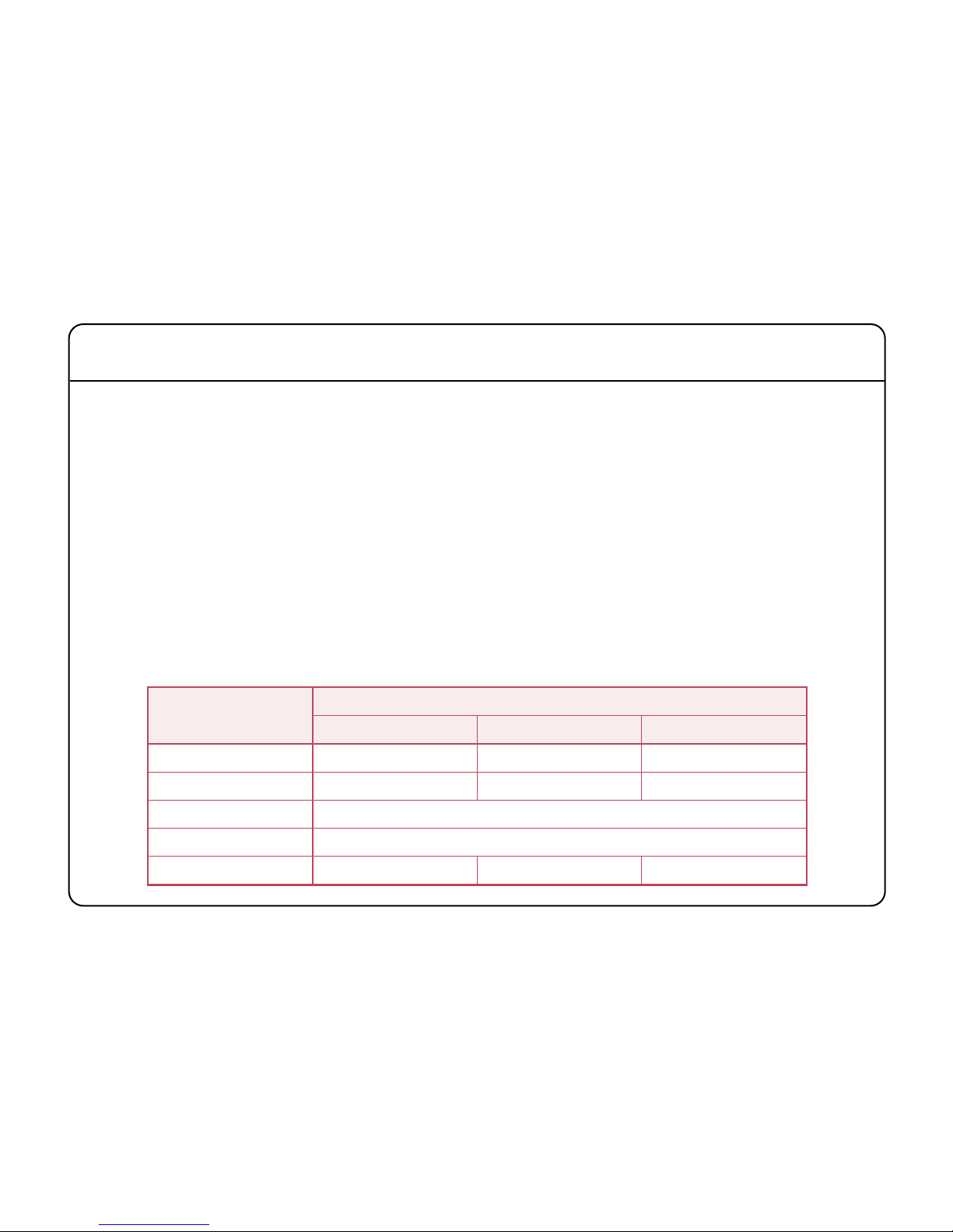
The number of channels available on each audio interface provided by the Alpha-Link is determined by the sample
rate and in certain circumstances by the mode of operation chosen.
Each unit can operate at one of four nominal sample rates; 44.1kHz, 48kHz, 88.2kHz and 96kHz. If locked to an
external clock source, each unit can also operate at a deviation of up to ±10% from these rates. Throughout this guide
we will often refer to the lower set of sample rates (44.1kHz, 48kHz) collectively as ‘Fs’ whilst the higher rates, being
twice the lower set, will be refered to as ‘2Fs’.
Early digital audio interfaces designed to run at 2Fs rates did so by modifying the way that data is packed into the
digital audio stream without increasing the actual transmission rate. This leads to a lower channel count for a given
interface but results in a 2Fs interface that is broadly compatible with the original Fs rate interface. Later improvements
for some interface types lead to ‘proper’ double speed 2Fs interfaces that did not compromise the channel count but
were no longer compatible with older Fs rate interfaces. These developments resulted in two different modes of
operation at the higher 2Fs rates; ‘Legacy’ or ‘SMUX’ and ‘High Speed’. The channel count differences are loosely
summarised in the following table and further information will be found towards the rear of this guide.
Audio Interface
Sample Rate and Mode
Fs 2Fs (Legacy/SMUX) 2Fs (High Speed)
ADAT 24 Channels 12 Channels n/a
AES/EBU 24 Channels 12 Channels 24 Channels
Analogue 24 Channels – irrespective of sample rate
Expansion Port 64 Channels – irrespective of sample rate
MADI 56 or 64 Channels 28 or 32 Channels 28 or 32 Channels
Page 8
4
Installation Notes
Please take time to read through this guide before installing your Alpha-Link. If however you are unable to resist that
temptation, do take note of the following points:
• Full connector pin-out details are provided in the Installation Guide.
• The nominal analogue I/O level of each Alpha-Link is +22dBu ≈ 0dB FS apart from Alpha-Link LIVE which is factory
configured for either +18dBu or +24dBu ≈ 0dB FS (see also Appendix C for unit identification).
• Your Alpha-Link unit can be rack mounted. Whilst the unit occupies 2U of rack space in a standard 19-inch rack,
do please leave (a 1U) space above and below the unit for cooling.
• It may be necessary to change the default CLOCK SOURCE – please refer to the Clock Source Selection discussion
on page 8 for further details.
• Please turn down, switch off or disconnect any connected amplifiers before re-configuring your Alpha-Link.
Changing signal routing and/or clock source can potentially produce loud audible clicks.
• To use an Alpha-Link unit with an SSL (or Soundscape) Mixpander PCI audio card, connect the Expansion Bus
port of the Alpha-Link unit to the Expansion Bus port of the Mixpander card using a Mixpander Expansion Bus
cable.
• If connecting to a Mixpander card, switch the computer that hosts the Mixpander card on and start the SSL Mixer
software
before
applying power to the Alpha-Link unit.
WARNING!
Where applicable, always switch the host computer and the Alpha-Link unit off before connecting or
disconnecting the Mixpander Expansion Bus cable or damage may result.
Page 9
5
Front Panel
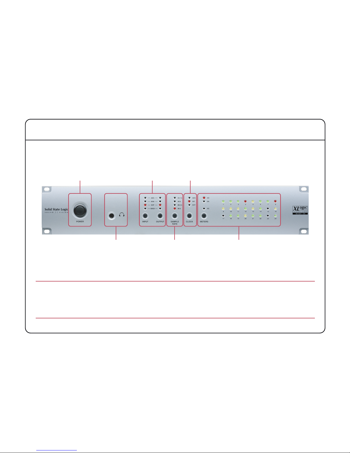
The front panels of each model of Alpha-Link are all broadly similar, differing only to reflect the different I/O options
provided (the unit illustrated here being an Alpha-Link MADI-SX).
Power Switch
This switch is used to power the Alpha-Link up or down.
The current front panel settings are stored in non-volatile memory when the unit is switched off, and recalled
the next time it is switched on. When the Alpha-Link is used in combination with an SSL (or Soundscape)
Mixpander card the SSL Mixer software controls all front panel settings and the settings defined in the software
will be restored as soon as the unit is powered up again (if still connected to the Mixpander card).
Power Switch
Routing Matrix
Control
Clock Source
Selection
Headphones
(except Alpha-Link LIVE)
Sample Rate
Selection
Signal Meters
Page 10
6
Headphones
A headphone socket is provided on all units apart from the Alpha-Link LIVE. This connector is a standard 0.25"
headphone jack socket and provides a stereo signal derived from analogue output channels 23 (Left) and 24 (Right).
The headphone signal level is fixed and can only be controlled in the digital domain by a suitable controller such
as the SSL Mixer software via an SSL (or Soundscape) Mixpander card.
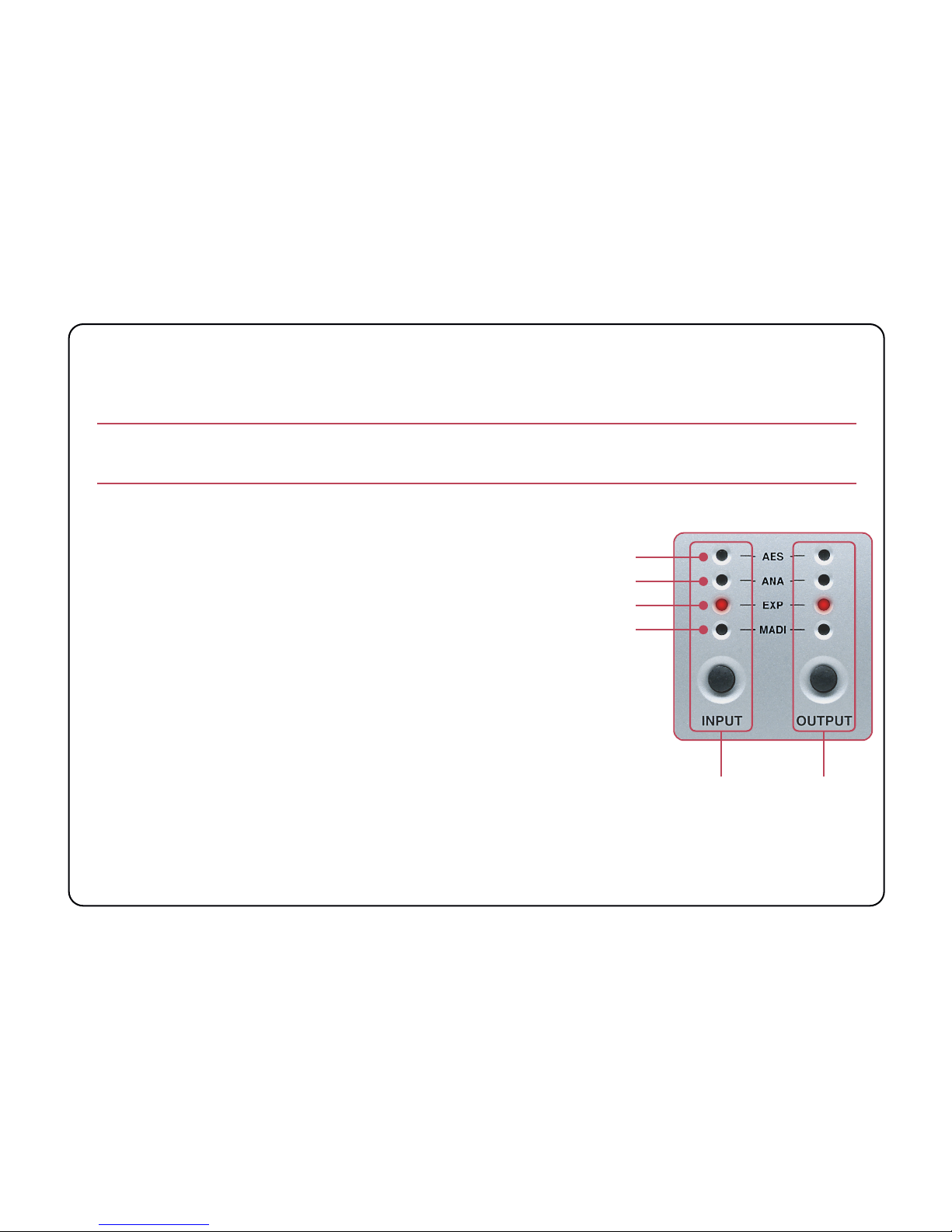
Routing Matrix Control
Every Alpha-Link contains a routing matrix which enables
routing of groups of signals between the inputs and outputs.
This routing matrix is controlled using two buttons – one for
INPUT, one for OUTPUT – along with a set of indicator LEDs
to show the routing setup. Using these two buttons, any input
group (ADAT or AES/EBU, Analogue, Expansion Bus or MADI)
can be connected to any output group.
If the Alpha-Link is connected to a Mixpander card via the Expansion Bus port it can
then act as multi-channel bi-directional format converter between the inputs and
outputs and the Expansion Bus. All routing in this case is determined by the SSL
Mixer software and the front panel routing matrix control is deactivated.
However the input and output signals are routed in the Alpha-Link, all routing is
performed to full 24-bit precision. There are no mixing functions in Alpha-Link so
whilst it is possible to use the routing matrix to route any single input to multiple
outputs, it is not possible for a single output to be fed from more than one input (selecting a second source for an
output will cause the second source to
replace
the original).
Input Button
and Indicators
Output Button
and Indicators
AES/EBU (or ADAT)
Analogue
Expansion Port
MADI
Page 11

7
Viewing and Setting Routing
Pressing the OUTPUT button repeatedly will cycle through the available output groups, the currently selected output
group being indicated by the corresponding LED. For each output group, the LEDs of the input column will indicate
which input group(s) are connected to that output group. To set or change the input group(s) connected to a given
output group:
• Use the OUTPUT button to select the required output.
• Press
and hold
the OUTPUT button.
• With the OUTPUT button held, each press of the INPUT button will step through each possible input group for
that output.
• Once the required routing has been selected, releasing the OUTPUT button will store and activate your selection.
Please note that the
INPUT
button works only in combination with the
OUTPUT
button.
Where capacity is available, two input groups may be assigned to one output group – the AES and analogue input
groups of an Alpha-Link MADI-SX or LIVE for example can both connect to the MADI output group. Where this is
possible it will be indicated by illuminating both input group LEDs whilst stepping through the different modes.
In cases where two input groups are connected to a single output group, the order in which input groups are
assigned is determined by the ‘Connection Mode’ described in the System Settings and Diagnostics section of
this guide. Channels will be routed in order, hence the ‘lower’ input group will be fully used before the routing
spills over to the ‘higher’ group. Where this split occurs will depend on the sample rate and channel count and
may result in some channels remaining unused or un-routed.
Page 12

8
Clock Source Selection
The Alpha-Link unit can operate either as a Clock Master device (‘Internal’
mode), or as a Clock Slave device locked to an external clock signal.
Possible external sources are:
• ADAT (Alpha-Link AX and MADI-AX)
• AES/EBU (Alpha-Link MADI-SX and LIVE)
• MADI (Alpha-Link MADI-AX, MADI-SX and LIVE)
• Wordclock (all units)
Pressing the CLOCK button will step through each of the possible options, each illuminating the
corresponding LED. When the button is released, the entire Alpha-Link will lock to that source. Note
that a flashing clock LED indicates that although the corresponding mode has been selected, the
Alpha-Link is not receiving a valid Master Clock signal via the selected port/input.
If either ADAT or AES/EBU are selected as an external clock source, it may be necessary to preset which ADAT
port – or AES/EBU input (port A only) – is used to derive the clock signal from. In the same manner, the ‘External’
source – MADI or Wordclock – must also be preset. Please refer to the System Settings and Diagnostics section
of this guide for details of how to preset these clock sources.
When the Alpha-Link unit is used as part of a Mixpander setup, the CLOCK button will be disabled and the clock source
must be selected in the SSL Mixer software. Note however that the Mixpander card only operates as a Clock Slave
and therefore it is the Alpha-Link which provides a clock signal to the Mixpander card.
Alpha-Link LIVE units are preconfigured to receive an external clock extracted from the incoming MADI stream
AES/EBU (or ADAT)
Internal
External
(MADI or Wordclock)
Page 13

9
Sample Rate Selection
The sample rate indicators show the current sample rate of the unit. When the
Alpha-Link clock source is set to ‘Internal’ (see opposite), pressing the SAMPLE
RATE button will step through each available sample rate (44.1kHz, 48kHz, 88.2kHz
and 96kHz) – as indicated by the corresponding LEDs.
When the clock source is set to an ‘external’ source (ADAT, AES/EBU, External or
MADI – the possible options depend on the particular Alpha-Link model) the
illuminated LED indicates the sample rate being received from that source. If there is an error
or if the received sample rate falls outside of the tolerance expected (±0.5% from nominal), all
sample rate LEDs will be off.
When locking to an ‘external’ source Alpha-Link will normally accept and lock to a wider clock
range at up to ±10% of the nominal rate, provided that the nominal rate corresponds to one
of the supported rates (44.1kHz, 48kHz, 88.2kHz and 96kHz). As noted above, if the sample rate from an external
source falls outside of the expected tolerance
all
sample rate LEDs will be extinguished although the clock source
LED should still indicate if a valid signal is being received. The exception to this extended external lock range is for
MADI if the unit has been set to interface the maximum 64 channels (32 channels at higher sample rates) where a
tolerance of ±0.5% applies.
If the Alpha-Link is used in combination with a Mixpander card the SAMPLE RATE button will be deactivated and the
sample rate LEDs will reflect the clock source and sample rate settings made in the SSL Mixer software.
If pressing the Sample Rate button has no effect – and the unit is not connected to a Mixpander card – check
that the clock source is set to ‘Internal’.
44.1kHz
48kHz
88.2kHz
96kHz
Page 14

10
Signal Meters
The meter section of the front panel provides simple tri-colour LED metering for either the 24 analogue inputs (AD)
or the 24 analogue outputs (DA), selectable using the METERS button.
For each input or output channel, the signal level is represented by the state of the LED with the corresponding
number. The LEDs respond to the signal level in the digital domain (in dB FS) as follows:
• OFF < –30dB FS (less than –8dBu applied to an analogue input; –12dBu or –6dBu for Alpha-Link LIVE)
• GREEN > –30dB FS (greater than –8dBu applied to an analogue input; –12dBu or –6dBu for Alpha-Link LIVE)
• AMBER > –3.0dB FS (greater than +19dBu applied to an analogue input; +15dBu or +21dBu for Alpha-Link LIVE)
• RED > –0.1dB FS (+22dBu or more applied to an analogue input; +18dBu or +24dBu for Alpha-Link LIVE)
Whilst the XSLED is located in this area of the front panel, it is has no metering function – its use is described
in the System Settings and Diagnostics section of this guide.
Input Metering
Output Metering
Tri-colour LED Meters
(24 Channels)
Page 15

11
System Settings and Diagnostics
Each Alpha-Link unit is configured by default to
work in a simple system. Many users however
may find that these defaults are not appropriate
for their setups. To cater for such situations, the
default settings may be adjusted using a set of
virtual switches, accessed from the Alpha-Link
front panel by placing the unit into a diagnostic
mode. These virtual switch settings are nonvolatile and are retained when the unit is power
cycled.
Diagnostic Mode
Holding the SAMPLE RATE and CLOCK buttons for at least 1.5 seconds when the Alpha-Link unit is switched on will
put it into diagnostic mode, indicated by a flashing XS LED. Diagnostic mode can be cancelled either by power cycling
the unit or by simultaneously pressing both the SAMPLE RATE and CLOCK buttons once more.
Any changes will be lost if the unit is power cycled; the internal memory is only written to if diagnostic mode
is exited by pressing both
SAMPLE RATE
and
CLOCK
buttons. Please allow time for any changes to take effect.
Picking a Page of Virtual Switches
Several pages of virtual switches are provided, the current page being indicated in AMBER by the lower row of meter
LEDs where the Channel 17 LED indicates Page 1, Channel 18 indicates Page 2 etc. Pressing the METERS button will
step through the available pages – each Alpha-Link model is different and may provide additional pages.
Current option settings for the
selected page
XS LED
flashes
Selected page
Selected
option
Page 16

12
Selecting an Option
For each page of switches, the middle row of meter LEDs indicates, in RED, the currently selected switch such that
Channel 9 LED indicates Switch 1, Channel 10 indicates Switch 2 etc. Pressing the OUTPUT button will cycle through
all switches for that page.
Setting an Option
The current setting of each option in the current page is indicated, in GREEN, by the state of the corresponding LED
in the first row of meter LEDs where the Channel 1 LED indicates the state of Option 1, Channel 2 indicates Option 2
etc. When an option is selected, pressing the INPUT button toggles the state of that option (ON or OFF).
Tables detailing the available options and their default settings will be found on the following pages. In each table
the relevant LED states are indicated as either extinguished (‘ ’) or illuminated (‘ ’).
Page 17

13
Firmware Version
Whilst in diagnostic mode, the Alpha-Link unit can also be set to display the
current firmware version by simultaneously pressing both the SAMPLE RATE and
CLOCK buttons. The firmware version will be displayed across the top row of
meter LEDs (1 through 8) whilst the buttons are pressed; releasing the buttons
will return the unit to normal operation.
The number will be displayed as a two digit binary number where LEDs 1 to 4
indicate the ‘major’ part and LEDs 5 to 8 the ‘minor’ part; the table here can be
used to convert the numbers displayed on the unit into decimal – for example
a version number of ‘1.2’ would display as ‘ ’ (where
‘ ’ indicates an illuminated LED).
LEDs Number
0
1
2
3
4
5
6
7
8
9
Page 18

14
Virtual Switches, Page One (Alpha-Link AX, MADI-AX and MADI-SX)
Settings in bold indicate defaults. Please also refer to the notes overleaf for details regarding each setting.
LED Option Setting LED State See Note
1 Number of MADI channels (not AX)
64 (32 at 2Fs)
1.
56 (28 at 2Fs)
2 MADI 2Fs data format (not AX)
High Speed
2.
Legacy (SMUX)
3 AES/EBU 2Fs data format (MADI-SX)
High Speed
2.
Legacy (SMUX)
4 Analogue/Digital connection mode
Analogue first (lowest)
3.
Digital first (lowest)
5 ADAT or AES/EBU channel status
Use
4.
Ignore
6
Sample rate when an Fs rate signal
is applied to the wordclock input
Fs
5.
2Fs
7 Wordclock output at 2Fs
Fs Clock
6.
2Fs Clock
8 Phase angle of Wordclock output
0°
7.
90°
Page 19

15
Virtual Switches, Page One (Alpha-Link LIVE)
Settings in bold indicate defaults. Please also refer to the notes opposite for details of each setting.
LED Option Setting LED State See Note
1 Number of MADI channels
64 (32 at 2Fs)
1.
56 (28 at 2Fs)
2 MADI 2Fs data format
High Speed
2.
Legacy (SMUX)
3 AES/EBU 2Fs data format
High Speed
2.
Legacy (SMUX)
4 Analogue/Digital connection mode
Analogue first (lowest)
3.
Digital first (lowest)
5 AES/EBU channel status
Use
4.
Ignore
6
Sample rate when an Fs rate signal
is applied to the wordclock input
Fs
5.
2Fs
7 Wordclock output at 2Fs
Fs Clock
6.
2Fs Clock
8 Phase angle of Wordclock output
0°
7.
90°
Page 20

16
Notes for Virtual Switches, Page One
1. There are two MADI channel formats; 56 or 64 channel. The 56 channel format allows for ±10% deviation from
the nominal sample rate whilst the 64 channel format uses the full capacity of the MADI stream fixed to the
selected sample rate. Not all MADI interfaces support both formats; please refer to the documentation for the
connected interface to determine the correct format to use. The MADI link transmission rate is always fixed hence
at higher or ‘2Fs’ sample rates (88.1kHz or 96kHz) channel capacity is halved to either 28 or 32 channels.
For Alpha-Link LIVE to control 8-RMP units, it is essential that the MADI port be set to operate in 56 channel
format; control signals are transmitted as data packets over channel 57.
2. These options are used at 2Fs rates only, either to determine the rate of the master clock or to set the data format
for that interface:
• If the unit is set to lock to the interface in question, these options determine how the clock signal embedded
in the selected clock source is interpreted
when the clock is below 57kHz
.
• When set to ‘Legacy (SMUX)’ the distributed clock will be at Fs rate.
• When set to ‘High Speed’ the distributed clock will be at 2Fs rate.
When Alpha-Link is provided with a 2Fs rate clock (above 57kHz) the distributed clock will always be 2Fs rate.
• If the unit is
not
set to lock to the interface in question, these options are used to set the data format for
that interface:
• When set to ‘Legacy (SMUX)’ a half-rate frame pattern will be used. This format is functionally compatible
with Fs rate interfaces and may be required to interface to older equipment.
• When set to ‘High Speed’ a proper 2Fs frame pattern will be used.
Page 21

17
3. When both analogue and digital (either ADAT or AES/EBU) input groups are both connected to the Expansion Bus
or MADI output groups, this option determines which input group feeds the output group first and hence affects
the order in which input channels are assigned to channels on the Expansion Bus or the MADI stream. Similarly,
when the Expansion Bus or MADI input groups are routed to both the analogue and ADAT output groups, this
switch also determines the order in which the input channels are split across the selected output groups. Please
refer to the Routing Matrix Control section on page 6 for more detail.
4. Many ADAT and AES/EBU interfaces embed sample rate information in the data stream which Alpha-Link can use
to configure itself. This information on occasion however might not correlate with the actual sample rate and in
such circumstances Alpha-Link can be set to ignore this information.
5. Further to point 2. opposite, when Alpha-Link is set to lock to external wordclock whilst operating at 2Fs, it may
be necessary to inform the unit how to treat the applied clock signal if that signal is at Fs rate.
6. The Wordclock output should normally follow the selected sample rate. When operating at 2Fs rates however it
may be necessary for the Wordclock output to run at either Fs or 2Fs rates
7. At the time of writing, only a fixed 90° angle is actually used so this option has no effect.
Page 22

18
Virtual Switches, Page Two (Alpha-Link AX and MADI-AX)
Settings in bold indicate defaults. Please refer to the notes overleaf for details regarding each setting.
LED Option Setting LED States See Note
1
2
ADAT clock source
ADAT In 1 –8
1.ADAT In 9 – 16
ADAT In 17 – 24
3 Clock source for ‘External’ selection
Wordclock
2.
MADI (MADI-AX only)
4 Unused n/a n/a –
5 Unused n/a n/a –
6 Unused n/a n/a –
7 Unused n/a n/a –
8 Unused n/a n/a –
Page 23

19
Virtual Switches, Page Two (Alpha-Link MADI-SX and LIVE)
Settings in bold indicate defaults. Please also refer to the notes overleaf for details regarding each setting.
LED Option Setting LED States See Note
1
2
AES/EBU clock source (port ‘A’ only)
AES/EBU In 1 & 2
3.
AES/EBU In 3 & 4
AES/EBU In 5 & 6
AES/EBU In 7 & 8
3 Clock source for ‘External’ selection
Wordclock (MADI-SX)
4.
MADI (LIVE)
4
AES/EBU sample rate converters
(port ‘A’ only)
Input 1 & 2 enabled
5.
Input 1 & 2 bypassed
5
Input 3 & 4 enabled
Input 3 & 4 bypassed
6
Input 5 & 6 enabled
Input 5 & 6 bypassed
7
Input 7 & 8 enabled
Input 7 & 8 bypassed
8 Unused n/a n/a –
Page 24

20
Notes for Virtual Switches, Page Two
1. Because the Alpha-Link AX and MADI-AX units carry three ADAT ports, there are three ports to choose from when
selecting an ADAT clock source. To enable one of the three ports to be selected the first two option switches
operate together.
2. For Alpha-Link MADI-AX only. When EXT is selected as the clock source, this can optionally be MADI instead of a
separate Wordclock feed. If MADI is selected here the clock signal embedded in the incoming MADI stream can
be used as the clock source.
3. The Alpha-Link MADI-SX and LIVE units can optionally lock to one of the four AES/EBU inputs provided on AES/EBU
port ‘A’. To enable one of these four inputs to be selected the first two option switches operate together.
For the Alpha-Link unit to lock to one of these inputs requires that the sample rate converter on that input is
also bypassed – see point 5. below.
4. When EXT is selected as the clock source, this can optionally be MADI instead of a separate Wordclock feed. If
MADI is selected here the clock signal embedded in the incoming MADI stream can be used as the clock source.
Note that for Alpha-Link MADI-SX this option defaults to Wordclock whilst Alpha-Link LIVE defaults to MADI.
5. Sample rate conversion is provided on the four AES/EBU inputs on AES/EBU port ‘A’. These converters can be
switched out in pairs.
Page 25

21
Virtual Switches, Page Three (Alpha-Link LIVE)
Settings in bold indicate defaults. Please also refer to the notes below for details regarding each setting.
1. The Expansion port on the rear of the Alpha-Link can be used to perform firmware upgrades. The Alpha-Link LIVE
unit runs different firmware to the other units in the Alpha-Link range but the Expansion port is unable to detect
this difference. Therefore to guard against accidental and incorrect firmware updates, the Alpha-Link LIVE will by
default not accept firmware updates over the Expansion port. At the time of writing, firmware update is not
possible over the MADI port.
LED Option Setting LED States See Note
1 Control Host
MADI
1.
Expansion Bus
2 Unused n/a n/a –
3 Unused n/a n/a –
4 Unused n/a n/a –
5 Unused n/a n/a –
6 Unused n/a n/a –
7 Unused n/a n/a –
8 Unused n/a n/a –
Page 26

22
Page 27

23
Appendix A – AES/EBU Interface
Inputs with Sample Rate Conversion
The inputs of AES/EBU port A (channels 1 through 8) have sample rate conversion available. These sample rate
converters combine a wide input-to-output sampling ratio with outstanding dynamic range and ultra low distortion,
resulting in high quality even at a 1:1 conversion (where many SRCs offer their lowest quality). In many instances the
converters may be left in-circuit albeit at the expense of increased delay through these inputs. If required, the sample
rate converters can be bypassed, in pairs, as described in the System Settings and Diagnostics section of this guide.
Input Sample Rate and Auxiliary Data
The input sample rate is measured from the selected AES/EBU stereo pair on port A (see page 17), not extracted from
the in-coming channel status bits. Information about ‘Legacy’ or ‘High Speed’ mode may be extracted from the channel
status bits if the in-coming stream contains this information but this should not be relied upon (see page 15).
Inputs without Sample Rate Conversion
The inputs of AES/EBU ports B and C (channels 9 through 24) do not have sample rate converters. Any signals applied
to these inputs (and port A if the sample rate converters are bypassed) must be synchronized to the system.
Output Auxiliary Data
The following will be set in the auxillary data fields of all AES/EBU output streams:
Channel Status Data Indication of the selected sample rate and mode (‘Legacy’ or ‘High Speed’)
All other channel status fields default to ‘1’
User Data Bit Always set low (‘0’)
Validity bit Always set true (valid)
Parity Bit Always recalculated
Page 28

24
Appendix B – Troubleshooting
Symptom Possible Solution
There is no sound, all the LEDs are off.
Check that the Alpha-Link unit is connected to the mains
supply and that the Power switch is in the ‘ON’ position. Check
the condition of the mains cable.
There is no sound. The ADAT, AES/EBU or
External Clock indicator LED flashes. The
Sample Rate LEDs are off.
Check that the device connected to the WordClock, MADI, ADAT
or AES/EBU port is set to transmit a suitable Master Clock
signal and operates at a supported sample rate.
The Input and Output buttons do not work.
The Input and Output LEDs are off.
The Clock button does not work.
The Sample Rate button does not work.
Is the Alpha-Link unit being used together with a Mixpander
card? If so, it is normal for these controls to be deactivated.
Otherwise, please contact Solid State Logic’s technical support.
When the Soundscape Mixer software is
started, a dialogue box states that the
Alpha-Link firmware is not compatible.
The Alpha-Link firmware needs to be updated. Firmware
updates require that the Alpha-Link be connected to an SSL or
Soundscape Mixpander card. If in doubt, please contact Solid
State Logic’s technical support.
The sound is distorted.
Use the front panel metering section to check the level of the
audio signals.
Page 29

25
Support FAQs
To access the latest support information on Alpha-Link,
please visit our online support site:
www.solidstatelogic.com/support
The information that you will find there is kept up to date
by our support staff to make sure all information is
accurate. All information is available to you 24 hours a day,
7 days a week.
If you can’t find an answer or solution to your issue, you
can submit a question on the site to our support staff for
resolution.
Page 30

26
Page 31

27
Appendix C – Alpha-Link Model Numbers
Alpha-Link is available in a variety of configurations. The following table correlates the major differences between the
different models with the unit part numbers to aid identification of units:
1. This is the SSL Part number for ordering and unit returns
2. This is the number found on the rear of the unit, adjacent to the unit Serial Number
3. Nominal maximum analogue I/O level for 0dB FS
Model SSL Part Number
1
Unit Identifier
2
Analogue I/O Level
3
Digital Interfaces
AX 726903X1 AFN-047 +22dBu ADAT
MADI-AX 726902X1 AFN-046 +22dBu ADAT, MADI
MADI-SX 726901X1 AFN-045 +22dBu AES/EBU, MADI
LIVE
726908X1 AFN-052 +24dBu
AES/EBU, MADI
726910X1 AFN-054 +18dBu
Page 32

Visit SSL at: www.solidstatelogic.com
82BSAM01A
© Solid State Logic
All Rights reserved under International and Pan-American Copyright Conventions
C10 HD, Mixpander, SSL, Solid State Logic, XLogic, XLogic Alpha-Link and XLogic Alpha-Link 8-RMP are trademarks of Solid State Logic
All other product names and trademarks are the property of their respective owners and are hereby acknowledged
No part of this publication may be reproduced in any form or by any means, whether mechanical or electronic,
without the written permission of Solid State Logic, Oxford, OX5 1RU, England
As research and development is a continual process, Solid State Logic reserves the right to change the features
and specifications described herein without notice or obligation.
Solid State Logic cannot be held responsible for any loss or damage arising directly or indirectly from any error
or omission in this manual.
E&OE
 Loading...