

Page 1

Super Analogue Mic Amp
Owner’s Manual
Page 2

Page 3

Solid State Logic
Super-Analogue™ Outboard
Owner’s Manual
82S6XL020E
S U P E R A N A L O G U E
M I C A M P
Page 4

XLogic Mic Amp Owner’s Manual
As research and development is a continual process, Solid State Logic reserves the right
to change the features and specifications described herein without notice or obligation
E&OE
Revision 0A, September 2003
Revision 0B, December 2003
Revision 0C, January 2004
Revision 0D, June 2004
Revision 0E, July 2004
Minor changes, November 2004
Minor changes, June 2005
Begbroke, Oxford, England, OX5 1RU • +44 (0)1865 842300
320 West 46th Street, 2nd Floor, New York, NY 10036, USA • +1 (1) 212 315 1111
Suite 401, 5757 Wilshire Blvd, Los Angeles, CA 90036, USA • +1 (1) 323 549 9090
3-55-14 Sendagaya, Shibuya-Ku, Tokyo 151-0051, Japan • +81 (0)3 5474 1144
7 bis, rue de la Victoire, le Blanc Mesnil, Paris 93150, France • +33 (0)1 48 67 84 85
Via Timavo 34, 20124 Milano, Italy • +39 (0)39 2328 094
Solid State Logic
Visit SSL at URL: http://www.solid-state-logic.com
All Rights reserved under International and Pan-American Copyright Conventions
Solid State Logic, SSL and XLogic are trademarks of Solid State Logic
All other product names and trademarks are the property of their respective owners
No part of this publication may be reproduced in any form or
by any means, whether mechanical or electronic, without the
written permission of Solid State Logic, Oxford, England
© Solid State Logic
Page 5

Page 1
Contents
1.0 Introduction 3
2.0 Safety Considerations 4
Safety Warnings 4
3.0 Installation 7
Setting the mains voltage selector 7
Mounting 7
Standalone Operation 7
Connecting to XL 9000 consoles 9
Connecting to XLogic Remote Control unit 11
Configuring the unit 13
4.0 Operation 15
Appendices:
A Internal Links and Fuses 17
Test Mode 17
B Connector Details 18
C Electronic Specification 24
D Calibration Information 26
E Physical Specification 27
F Environmental Specification 27
Page 6
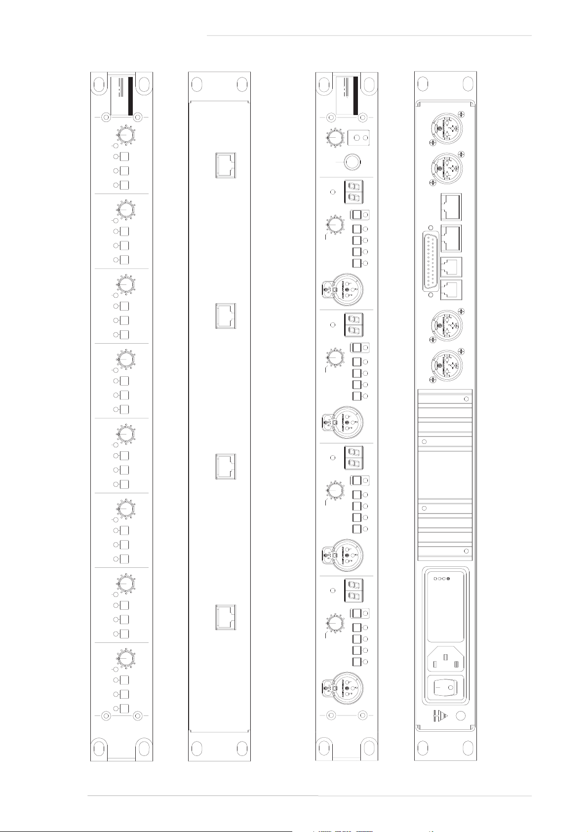
XLogic Mic Amp Remote (front)
XLogic Mic Amp Remote (rear)
XLogic Mic Amp (rear)
XLogic Mic Amp (front)
XLogic Mic Amp Owner’s Manual
Page 2
XL
SUPER ANALOGUE
M I C A M P
ogic
MONITOR
REMOTE
SIGNAL
CHANNEL
GAIN
HI
Z
-20
dB
48V MON
Ø
+18 +72
dB
SIGNAL
CHANNEL
GAIN
HI
Z
-20
dB
48V MON
+18 +72
dB
SIGNAL
CHANNEL
GAIN
HI
Z
-20
dB
48V MON
Ø
+18 +72
dB
SIGNAL
CHANNEL
GAIN
HI
Z
-20
dB
48V MON
Ø
+18 +72
dB
Solid
State
Logic
Ø
GAIN
dB
+18 +72
Ø
0/LD
MIC 1
HI
Z
XL
S U P E R A N A L O G U E
M I C A M P R E M O T E
ogic
-20
dB
GAIN
dB
+18 +72
Ø
0/LD
MIC 2
HI
Z
-20
dB
GAIN
dB
+18 +72
Ø
0/LD
MIC 3
HI
Z
-20
dB
GAIN
dB
+18 +72
Ø
0/LD
MIC 4
HI
Z
-20
dB
GAIN
dB
+18 +72
Ø
0/LD
MIC 5
HI
Z
-20
dB
GAIN
dB
+18 +72
Ø
0/LD
MIC 6
HI
Z
-20
dB
GAIN
dB
+18 +72
Ø
0/LD
MIC 7
HI
Z
-20
dB
GAIN
dB
+18 +72
Ø
0/LD
MIC 8
HI
Z
-20
dB
Solid
State
Logic
REMOTE 1/2REMOTE 5/6REMOTE 7/8 REMOTE 3/4
Solid State Logic
OXFORD • ENGLAND
MIC OUT 4 MIC OUT 3
MIC OUT 2 MIC OUT 1
AUDIO/
CONTROL
MON IN MON OUT REM 3/4 REM 1/2
100V
120V
220V
240V
Page 7

1.0 Introduction
The XLogic Mic Amp is a 1U rack mounting unit containing four ultra high quality microphone amplifiers,
utilising SSL’s Super Analogue technology. The unit can be controlled either locally, from the XLogic Mic Amp
Remote Control or from an XL 9000 console, allowing the mic amp to be placed close to the microphone in order
to eliminate the signal degradation caused by long mic cables.
The object of this manual is to provide purchasers of the XLogic Mic Amp with information in the following
areas:
• Safety considerations
• Installation requirement
• Electrical connections and cabling
• Connector pin-outs
• Specifications and physical dimensions
Warranty
The warranty period for this unit is 12 months from date of purchase.
In Warranty Repairs
In the event of a fault during the warranty period the unit must be returned to your local distributor who will
arrange for it to be shipped to Solid State Logic for repair. All units should be shipped to Solid State Logic in their
original packaging. Solid State Logic can not be held responsible for any damage caused by shipping units in
other packaging. In such cases Solid State Logic will return the unit in a suitable box, which you will be charged
for. Please do not send manuals, power leads or any other cables - Solid State Logic can not guarantee to return
them to you. Please also note that warranty returns will only be accepted as such if accompanied by a copy of
the receipt or other proof of purchase.
Out of Warranty Repairs
In the event of a fault after the warranty period has expired, return the unit in its original packaging to your local
distributor for shipment to Solid State Logic. You will be charged for the time spent on the repair (at Solid State
Logic's current repair rate) plus the cost of parts and shipping.
Page 3
Introduction
Page 8

2.0 Safety considerations
This section contains definitions and warnings, and practical information to ensure a safe working environment.
Please take time to read this section before undertaking any installation work.
2.1 Definitions
‘Maintenance’
All maintenance must be carried out by fully trained personnel. Note: it is advisable to observe suitable ESD
precautions when maintenance to any part is undertaken.
‘Non-User Adjustments’
Adjustments or alterations to the equipment may affect the performance such that safety and/or international
compliance standards may no longer be met. Any such adjustments must therefore only be carried out by fully
trained personnel.
‘Users’
This equipment is designed for use solely by engineers and competent operators skilled in the use of professional
audio equipment.
‘Environment’
This product is a Class A product intended to form an integrated component part of a professional audio
recording, mixing, dubbing, film, TV, radio broadcast or similar studio wherein it will perform to specification
providing that it is installed according to professional practice.
2.3 Installation
Voltage Selection and Fusing
All XLogic units have selectable voltage inlets. Always confirm that the input mains voltage range is set correctly
before applying power. Always isolate the mains supply before changing the input range setting.
If it is ever necessary to replace a blown mains-fuse, then always use the correct rating and type of replacement.
If a correctly rated fuse continues to blow, then a fault exists and the cause should be investigated or the unit
returned to Solid State Logic for repair/replacement as appropriate.
Details of mains settings and correct fuse ratings can be found in Section 3.1 and Appendix A of this manual.
Safety Earth Connection
Any mains powered item of Solid State Logic equipment that is supplied with a 3-core mains lead (whether
connectorised or not) should always have the earth wire connected to the mains supply ground. This is the safety
earth and grounds the exposed metal parts of the racks and cases and should not be removed for any reason.
2.2 Electrical Safety Warning
When installing or servicing any item of Solid State Logic equipment with power applied, when cover
panels are removed, HAZARDOUS CONDITIONS CAN EXIST.
These hazards include: High voltages
High energy stored in capacitors
High currents available from DC power busses
Hot component surfaces
Any metal jewellery (watches, bracelets, neck-chains and rings) that could inadvertently come into contact
with uninsulated parts should always be removed before reaching inside powered equipment.
XLogic Mic Amp Owner’s Manual
Page 4
Page 9

Mains Supply and Phases
Solid State Logic equipment is designed for connection to single phase supplies with the Neutral conductor at
earth potential - category TN - and is fitted with a protective fuse in the Live conductor only. It is not designed
for use with Phase (Live) and Neutral connections reversed or where the Neutral conductor is not at earth
potential (TT or IT supplies).
Mains cables will be coded with the following colour scheme:
LIVE: Brown
NEUTRAL: Blue
EARTH: Yellow/Green
Mains Isolation and Over-Current Protection
An external disconnect device is required for this equipment which must be installed according to current wiring
regulations. A detachable power cord, as fitted to this equipment, is a suitable disconnect device.
An external over-current protection device is required to protect the wiring to this equipment which must be
installed according to the current wiring regulations. The fusing or breaking-current are defined in the product
specification. In certain countries this function is supplied by use of a fused plug.
CE Certification
Note that the majority of cables supplied with SSL equipment are fitted with ferrite rings at each end. This is to
comply with current European CE regulations and these ferrites should not be removed.
If any of the unit metalwork is modified in any way this may the adversely affect the CE certification status of
the product.
FCC Certification
The XLogic unit has been tested and found to comply with the limits for a Class A digital device, pursuant to
part 15 of the FCC Rules. These limits are designed to provide reasonable protection against harmful interference
when the equipment is operated in a commercial environment. This equipment generates, uses, and can radiate
radio frequency energy and, if not installed and used in accordance with the instruction manual, may cause
harmful interference to radio communications. Operation of this equipment in a residential area is likely to cause
harmful interference in which case the user will be required to correct the interference at his own expense.
Safety Considerations
Page 5
Page 10
XLogic Mic Amp Owner’s Manual
Page 6
240
120
100
240
230
120
100
240
230
120
100
240
230
100
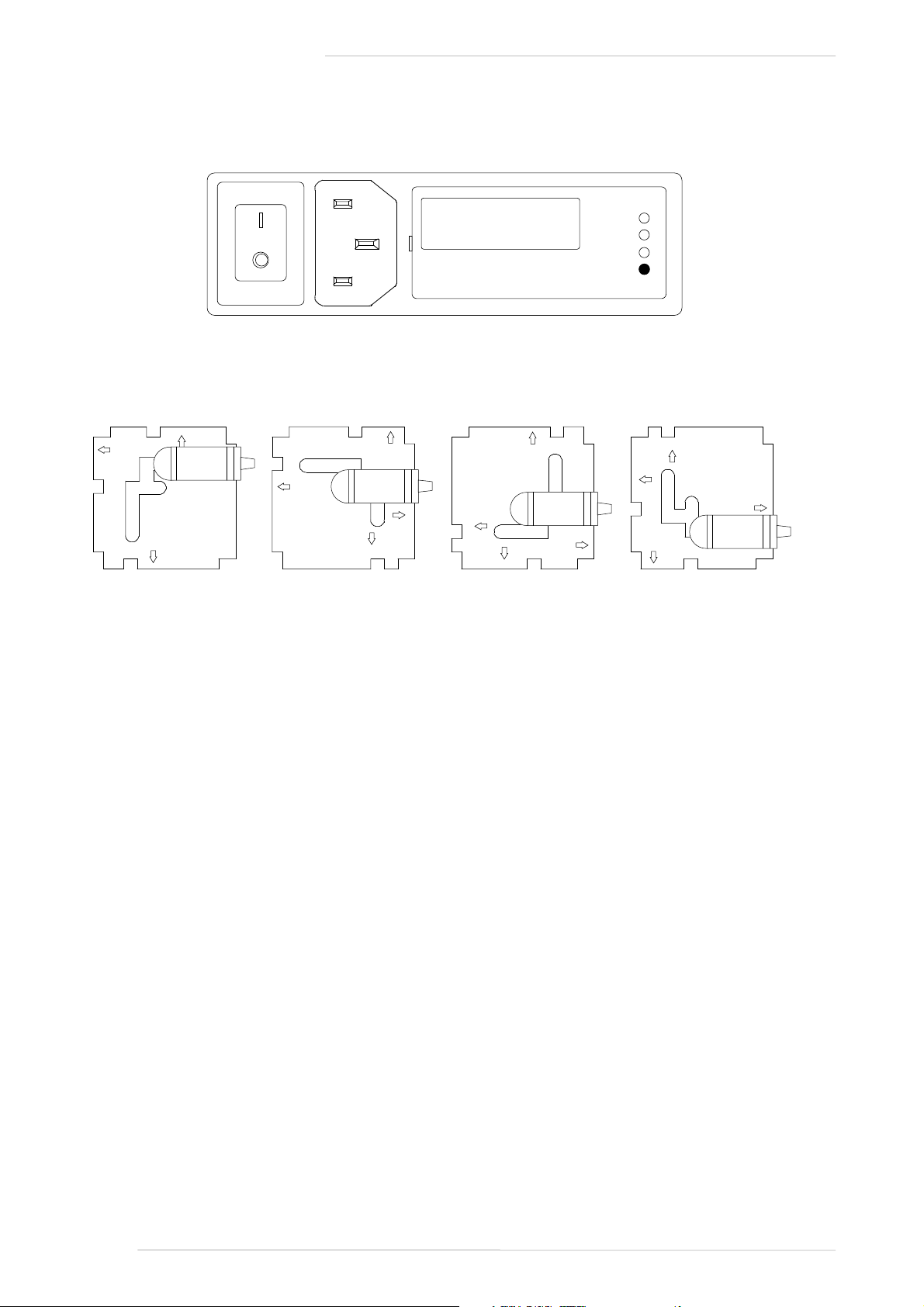
100V
120V
230V
240V
100V Setting
(Use for 90-105V)
120V Setting
(Use for 105-125V)
230V Setting
(Do not use)
240V Setting
(Use for 220-240V)
Mains Input Module
Mains Input Programming PCB
These diagrams show the PCB arrangements for the different voltage settings.
Note that where the mains voltage is a nominal 230V, the ‘240V Setting’ should be used – not the ‘230V Setting’!
Page 11

3.0 Installation
3.1 Voltage Selection
Before connecting the mains supply ensure that the voltage range selector next to the IEC socket on the rear of
the unit is correctly set. The input setting must be confirmed before applying power. The input module can be
configured to be one of 4 voltage settings. The setting is indicated by a plastic pin protruding through the
appropriate hole in the fuse panel.
The setting is altered by a small vertical PCB which can be fitted in 4 positions.
To change the setting:
Switch off and remove the IEC lead.
Using a small flat-bladed screwdriver, lever open the fuse panel to the right of the connector.
At the right hand side is a vertical PCB with a plastic key which indicates the setting. Using pliers, pull
out the PCB.
The PCB has to be rotated until the desired voltage is shown along the edge which plugs into the module.
The plastic key (and this bit is quite fiddly) must also be rotated so that it points out of the module and so
that the round pin aligns with the appropriate hole in the cover panel; (refer to the diagrams opposite).
Re-insert the PCB and replace the fuse panel. The plastic pin should project through the appropriate hole.
3.2 Mounting
The XLogic unit is designed to be rack mounted. It is 1RU (44.5mm/1.75 inch) high. Its depth is:
325 mm/12.8 inches not including heatsink
365 mm/14.3 inches including heatsink
400 mm/15.75 inches including connectors
Please note that the rack ears of early XLogic Mic Amp units are not capable of supporting the full weight of the
unit. Therefore if the unit is to be rack-mounted, it must either be mounted on suitable rack shelves or be fitted
with a pair of support brackets to reinforce the rack ears – do not rely on just the basic front panel for rack-mounting
the unit. Later XLogic Mic Amp units incorporate reinforcement brackets into the chassis and so are suitable for
direct rack-mounting. Should your unit require them, pairs of support brackets (SSL Part No.: 629943XR) are
available from your local distributor.
A 1RU space must be left above each unit to ensure adequate ventilation.
3.3 Standalone Operation
Before mounting the unit in the rack check that the front panel displays are correct by powering up the unit.
Section 3.6 describes how to set the displays for your installation.
If several units are to be mounted in the same rack then the headphone monitor and talkback bus should be
connected between the units by connecting the ‘MON IN’ and ‘MON OUT’ connectors on adjacent units, using
the supplied RJ11-RJ11 cable (SSL Part No.66C67240).
The headphone output monitors any channel selected to ‘MON’ plus an external talkback input. The talkback
input can be connected to a line level console talkback output if required. This signal is bussed between units on
the monitor link cables. Use an RJ11 to female XLR adaptor (SSL Part No. 66C67241) to connect talkback to a free
MON IN or MON OUT connector. One adaptor cable is supplied with each unit.
Once these connection have been made apply power to the unit(s). Ensure that the yellow ‘REMOTE’ LED on
the right of the front panel is not lit. If it is lit, use a small screwdriver or similar to turn off the recessed
‘REMOTE’ switch below the LED. Finally connect the male XLR connectors on the rear of the unit to the line level
inputs of your console or recorder and your microphones to the XLR inputs on the front of the unit.
Installation
Page 7
Page 12
VIDEO 1 VIDEO 2
REMOTE MIC AMPS 1-4
REMOTE MIC AMPS 5-8
REMOTE MIC AMPS 9-12
REMOTE MIC AMPS 13-16
REMOTE MIC AMPS 17-20
REMOTE MIC AMPS 21-24
REMOTE MIC AMPS 25-28
REMOTE MIC AMPS 29-32
REMOTE MIC AMPS 33-36
REMOTE MIC AMPS 37-40
REMOTE MIC AMPS 41-44
REMOTE MIC AMPS 45-48
Channels 1-4
Channels 5-8
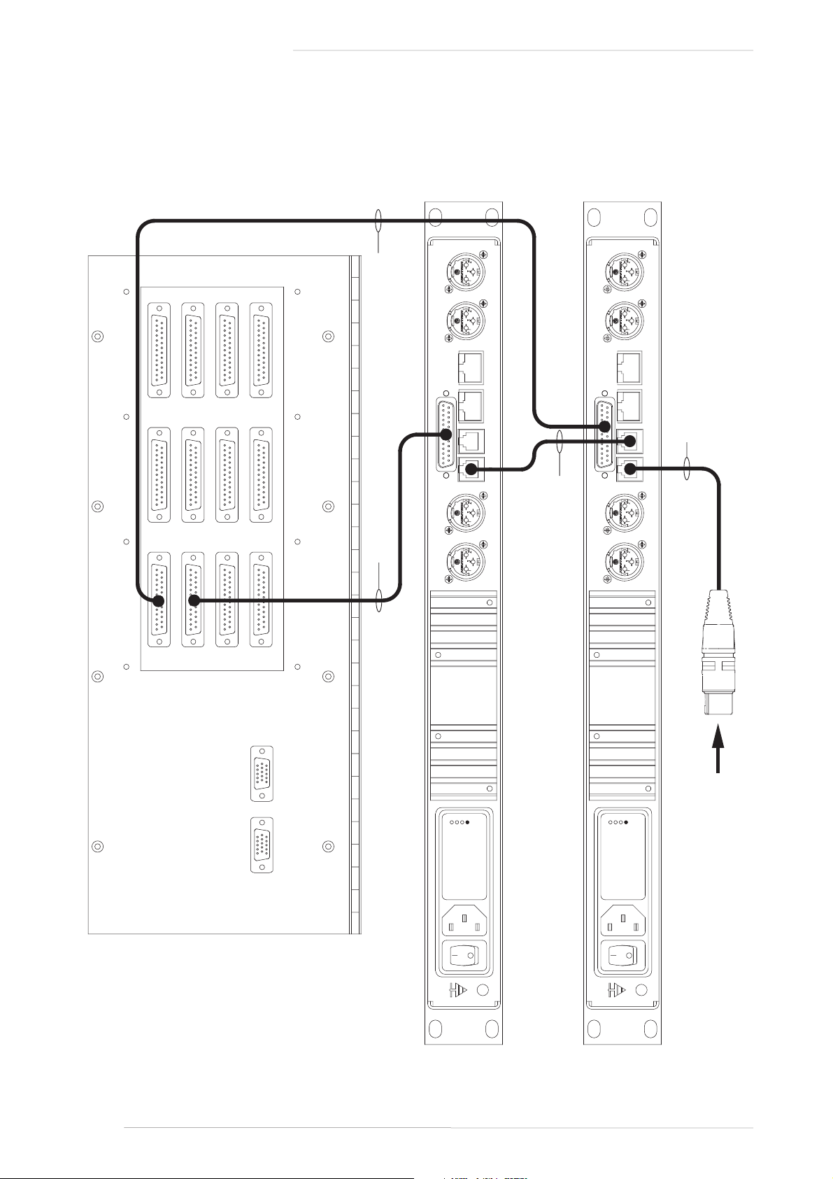
Console switched talkback output
RJ11-RJ11 monitor bus link
SSL Pt. No. 66C67240
XLR - RJ11 talkback input cable
SSL Pt. No. 66C67241
25wD - 25wD console to mic amp cable. SSL Part No.
66CM10xx , where xx is the cable length in meters
MIC OUT 4
MIC OUT 3
MIC OUT 2
MIC OUT 1
AUDIO/
CONTROL
MON IN MON OUT REM 3/4 REM 1/2
MIC OUT 4
MIC OUT 3
MIC OUT 2
MIC OUT 1
AUDIO/
CONTROL
MON IN MON OUT REM 3/4 REM 1/2
100V
120V
220V
240V
100V
120V
220V
240V
XLogic Mic Amp Owner’s Manual
Page 8
Console Wiring Diagram
Page 13

3.4 Connection to XL 9000 Consoles
Remote mic amp prewiring has been fitted to many, but not all XL 9000 consoles. In many cases only a small
number of channels have been wired. Check which (if any) bays of the console have been prewired for remote
mic amps. Wiring can be retrofitted to any XL 9000 console if required - contact your local office or distributor
for more information. The prewiring comprises two parts – two control signals from each channel plus a relay
card that automatically switches the channel line input to the output of the XLogic Mic Amp.
Connection to an XL 9000 console is made from the 25 way ‘D’ type connector on the rear of the unit. This carries
both audio and control signals. Depending on the age of the console the audio inputs and control outputs will
either be on 96 pin Canon DL connectors (which were used on the original 24 channel ‘SuperPre’ mic amp) which
have 24 circuits of audio and control on separate connectors, or on 25 way ‘D’ type male connectors with the
same pin out as the Mic Amp unit. If the console if wired with DL connectors then a DL to 25 way ‘D’ type male
adaptor cable will be required.
Interconnecting cables may be ordered from Solid State Logic or supplied by the facility. See the block diagrams
opposite. Appendix B contains pinouts for all connectors. Appendix B also includes wiring information to build
an adaptor cable to connect the audio and control DLs to 25 way ‘D’ type connectors.
The cable used should be 8 pair individually jacketed multicore with an overall screen such as Belden 1512C.
Connectors should have metal or metallised covers. Connect the overall shield to the connector cover at both
ends.
If several units are to be mounted in the same rack then the headphone monitor and talkback bus should be
connected between the units by connecting the ‘MON IN’ and ‘MON OUT’ connectors on adjacent units, using
the supplied RJ11-RJ11 cable (SSL Part No.66C67240).
The headphone output monitors any channel selected to ‘MON’ plus an external talkback input. The talkback
input can be connected to a line level console talkback output if required. This signal is bussed between units on
the monitor link cables. Use an RJ11 to female XLR adaptor (SSL Part No. 66C67241) to connect talkback to a free
MON IN or MON OUT connector. One adaptor cable is supplied with each unit.
Once these connection have been made apply power to the unit(s). Ensure that the yellow ‘REMOTE’ LED on
the right of the front panel is lit. If it is not lit use a small screwdriver or similar to turn on the recessed ‘REMOTE’
switch below the LED.
Finally check that:
• The channel number displays on the front of the unit match the numbers of the channels the unit is
connected to.
• When you pull up the Mic Gain controls on the connected channels the ‘MIC’ LED changes colour from
red to green.
• The motorised pots and the remote controlled switches (48V, PAD and Hi-Z) operate correctly from the
XL 9000 when ‘Remote’ is selected and that they can be controlled locally when ‘Remote’ is not selected.
• When you connect a microphone to the Mic Amp input signal appears on the input of the correct channel
of the console.
Installation
Page 9
Page 14

REMOTE 1/2
REMOTE 5/6
REMOTE 7/8
REMOTE 3/4
Solid State Logic
OXFORD • EN GLAND
RJ45-RJ45 (Cat 5) shielded pin to pin cable.
SSL Pt.No. 66C673xx where xx is length in metres
Channels 1-4
Channels 5-8
Console switched talkback output
RJ11-RJ11 monitor bus link
SSL Pt. No. 66C67240
XLR - RJ11 talkback input cable
SSL Pt. No. 66C67241
MIC OUT 4
MIC OUT 3
MIC OUT 2
MIC OUT 1
AUDIO/
CONTROL
MON IN MON OUT REM 3/4 REM 1/2
MIC OUT 4 MIC OUT 3
MIC OUT 2
MIC OUT 1
AUDIO/
CONTROL
MON IN MON OUT REM 3/4 REM 1/2
100V
120V
220V
240V
100V
120V
220V
240V
XLogic Mic Amp Owner’s Manual
Page 10
Remote Control Wiring Diagram
Page 15

3.5 Connection to XLogic Mic Amp Remote
The XLogic Mic Amp Remote (see drawing on page 2) is a 1U panel, approximately 100mm deep. Each unit will
control one or two XLogic Mic Amp units (eight channels in total). It connects to each XLogic Mic Amp by two
shielded RJ45 cables and is powered from the XLogic Mic Amp. Four 20 metre cables are supplied with each
remote unit. These cables can be extended up to a maximum length of 100 metres using standard shielded Cat
5 network cable(s) with a minimum conductor size of 26AWG. Use of 24AWG cable allows the cable to be
extended to a maximum of 200 metres. To ensure compliance with EU EMC regulations Solid State Logic
recommend fitting a ferrite bead close to each end of the cable.
Note that these cables carry +12 volts to power the remote unit and must not be connected to your ethernet network. Serious
damage to the ethernet repeater may result if this is done.
If several units are to be mounted in the same rack then the headphone monitor and talkback bus should be
connected between the units by connecting the ‘MON IN’ and ‘MON OUT’ connectors on adjacent units, using
the supplied RJ11-RJ11 cable (SSL Part No.66C67240). The drawing in Section 3.5 shows this.
The headphone output monitors any channel selected to ‘MON’ plus an external talkback input. The talkback
input can be connected to a line level console talkback output if required. This signal is bussed between units on
the monitor link cables. Use an RJ11 to female XLR adaptor (SSL Part No. 66C67241) to connect talkback to a free
MON IN or MON OUT connector. One adaptor cable is supplied with each unit.
Once these connection have been made apply power to the unit(s). Ensure that the yellow ‘REMOTE’ LED on
the right of the front panel is on. If it is off use a small screwdriver or similar to turn on the recessed ‘REMOTE’
switch below the LED.
Check that the motorised pots and the remote controlled switches (Phase, –20dB and Hi-Z) operate correctly
from the Mic Amp Remote control unit when ‘REMOTE’ is selected and that they can be controlled locally when
‘REMOTE’ is not selected.
Finally connect the male XLR connectors on the rear of the unit to the line level inputs of your console or recorder
and your microphones to the XLR inputs on the front of the unit.
Installation
Page 11
Page 16

XLogic Mic Amp Owner’s Manual
Page 12
Channel
LK5
BCD Switch
Front Panel Displays
Address *
Position
Setting
Display 1
Display 2
Display 3
Display 4
00000a0DPDPDPDP00001a1123400010a2567800011a3910111200100a41314151600101a51718192000110a62122232400111a72526272801000a82930313201001a93334353601010aA3738394001011aB4142434401100aC4546474801101aD4950515201110aE5354555601111bF5758596010000b06162636410001b16566676810010b26970717210011b37374757610100b47778798010101b58182838410110b68586878810111b78990919211000b89394959611001b9DPDPDPDP11010bADPDPDPDP11011bBDPDPDPDP11100bCDPDPDPDP11101bDDPDPDPDP11110bEDPDPDPDP11111bFDPDPDPDPNote:
'DP' - decimal point
* Pull address pins marked '1' to 0V to enable.
Table 1: Channel Display Setting - Normal Operation
Page 17

3.6 Configuring the XLogic Mic Amp
There are a number of internal link settings, most of which should not normally require adjustment – see
Appendix A for a full listing. Those links that change the operation of the unit are described below.
Setting the Channel Displays
If the unit is connected to an XL 9000 console the 5 address bits on the 25 way ‘D’ type Audio/Control connector
are set on the console channel bus card so that the channel displays automatically show the channels the unit is
connected to.
When controlled locally or from the XLogic Mic Amp Remote
control unit, the channel displays can be set by adjusting a rotary
switch that is accessible through the lid of the case – see the
drawing to the right. The rotary switch has 16 positions, allowing
the front panel display to show channel numbers in the range 1
to 60. To display channel numbers above 60 the internal jumper
LK5 (screened BIT 5) should be moved to position ‘b’.
To perform this adjustment, make a note of the front panel
displays, power-down the unit and insert a thin flat bladed
screwdriver. Referring to both the screening on the top cover and
to Table 1. opposite, set the switch as required. Remove the
screwdriver and re-apply power.
Note that the rotary switch position is ignored if the unit is connected to an XL 9000 console but that LK5 will
always increase the displayed number by 60 when set to position ‘b’.
Note. It is recommended that this adjustment is not performed with power applied as a mis-placed screwdriver can cause
damage to the XLogic Mic Amp!
Changing the Remote +48V and Phase Switch Functions
If the unit is to be controlled from an XLogic Mic Amp Remote control unit then the phantom power selection is
normally made from the Mic Amp front panel and phase is remote controlled. If the unit is to be controlled from
an XL 9000 then phase is normally controlled from the Mic Amp front panel and phantom power is controlled
from the console. This selection is automatic – the unit detects if any of the address inputs on the Audio/Control
25 way ‘D’ type connector are connected to ground and selects ‘XL’ mode accordingly. The selection can be
reversed by moving the internal jumper LK6 (screened PHAS/PHAN) to position ‘b’.
25-28/85-88
21-24/81-84
17-20/77-80
13-16/73-76
9-12/69-72
5-8/65-68
1-4/61-64
0
29-32/89-92
33-36/93-96
37-40
41-44
45-48
49-52
53-56
57-60
Configuration
Page 13
Page 18
XLogic Mic Amp Owner’s Manual
Page 14
+48V
PHANTOM
POWER
+48V
-20dB
Hi-Z
MIC
TRIM
+18 — +78dB
MONØ
+
-
25wD
25wD
MON IN/MON OUT
Headphone
amp
Stereo Jack
DC Control
from Console
25wD
RJ45 -1
DC Control
from remote
PIC Controller
Channel 1
RST
+48V
PHANTOM
POWER
+48V
-20dB
Hi-Z
MIC
TRIM
+18 — +78dB
MONØ
+
-
25wD
25wD
DC Control
from Console
RJ45 -1
DC Control
from remote
PIC Controller
Channel 2
RST
+48V
PHANTOM
POWER
+48V
-20dB
Hi-Z
MIC
TRIM
+18 — +78dB
MONØ
+
-
25wD
25wD
DC Control
from Console
RJ45 -2
DC Control
from remote
PIC Controller
Channel 3
RST
+48V
PHANTOM
POWER
+48V
-20dB
Hi-Z
MIC
TRIM
+18 — +78dB
MONØ
+
-
25wD
25wD
DC Control
from Console
RJ45 -2
DC Control
from remote
PIC Controller
Channel 4
RST
∑
+5V
Talkback Input
5
0
A
B
C
D
E
976
5
4
3
2
1
8
PIC Display
Controller
REMOTE
REM
REM
REM
REM
Page 19

4.0 Operation
The XLogic Mic Amp is a 1U rack mounting unit containing four ultra high quality microphone amplifiers,
utilising Solid State Logic’s Super Analogue technology. The unit can be controlled locally, from the XLogic Mic
Amp Remote unit or from an XL 9000 console, allowing the mic amp to be placed close the microphone in order
to eliminate the signal degradation caused by long mic cables.
The ‘REMOTE’ switch on the right of the front panel (accessible through the hole above the ‘Remote’ LED)
switches the unit between remote and local modes.
In local mode all the front panel switches and the microphone gains can be set from
the front panel of the unit. Note that because of the servo motor and gear box the
gain control is stiffer than a normal SSL potentiometer. In remote mode the gain
controls and three of the front panel switches are controlled from either the XLogic
Mic Amp Remote unit or an XL 9000 console. The MON switch and either the phase
or 48V switch remain local. Which switch is local depends on whether the unit is
connected to an XL 9000 or to an XLogic Mic Amp Remote unit (and also on the
position of the internal PHAS/PHAN link – see section 3.6). The XL 9000 normally
controls 48V, Hi-Z and –20dB switches. The Mic Amp Remote normally controls
phase, Hi-Z and –20dB switches.
Please note that connecting a microphone to the XLogic Mic Amp with phantom power switched on is not advised as it may
cause damage to either the microphone or the input stage of the XLogic Mic Amp.
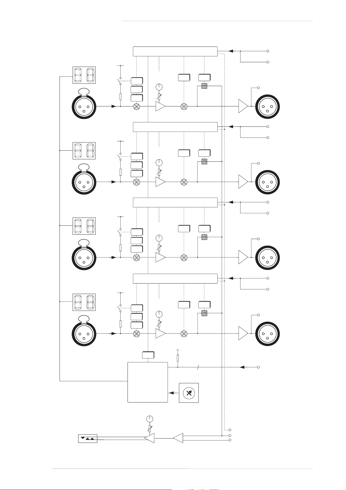
Each channel has an XLR input on the front panel. The mic amp gain is controlled by a motorised potentiometer.
Dedicated switches control phase reverse, phantom power, input impedance and 20dB pad. A dual seven
segment display shows the channel number. These are set from either an internal BCD switch (accessible through
the lid of the unit) or by links on the 25 way ‘D’
type connector on the rear of the unit. XL 9000
consoles automatically configure the unit to
show which channels the unit is connected to.
See section 3.6 for instructions on how to change
the channel displays.
Each channel has two outputs – one on the
Audio/Control 25 way ‘D’ type connector for
connection to an XL 9000 console and one on a
male XLR. Control inputs appear on both the 25
way ‘D’ type ‘Audio/Control’ connector for connection to an XL 9000 and also on two RJ45 connectors for
connection to an XLogic Mic Amp Remote. The RJ45 connectors also carry power to the remote unit. Note that
only one of the control inputs should be connected.
The headphone jack and level control at the left of the unit is fed by a mix of the
talkback input on the rear panel ‘MON’ connectors and any microphone channel
that is selected to ‘MON’. The headphone outputs and talkback inputs on multiple
units can be linked using the ‘MON IN’ and ‘MON OUT’ RJ11 connectors on the
rear of the unit (see sections 3.3 and 3.4). The MON switches inter cancel between
channels and between multiple units if they are linked, so any input can be
monitored without having to move the headphones to a different unit.
The block diagram opposite shows the signal path through the unit.
Operation
Page 15
SIGNAL
CHANNEL
GAIN
HIZ-20
dB
48V MON
ø
+18 +72
dB
MONITOR
REMOTE
MONITOR
REMOTE
Page 20

XLogic Mic Amp Owner’s Manual
Page 16
Channel
LK5 (bit 5)
BCD Switch
Front Panel Displays
Address *
Position
Setting
Display 1
Display 2
Display 3
Display 4
xxxxxa088888888xxxxxa1seg a
seg a
seg a
seg a
xxxxxa2
seg b
seg b
seg b
seg b
xxxxxa3
seg c
seg c
seg c
seg c
xxxxxa4
seg d
seg d
seg d
seg d
xxxxxa5
seg e
seg e
seg e
seg e
xxxxxa6
seg f
seg f
seg f
seg fxxxxxa7seg g
seg g
seg g
seg g
xxxxxa8DPDPDPDPxxxxxa9xxxxxaAxxxxxaBxxxxxaCxxxxxaDxxxxxaExxxxxbFxxxxxb00000xxxxxb111111111xxxxxb222222222xxxxxb333333333xxxxxb444444444xxxxxb555555555xxxxxb666666666xxxxxb777777777xxxxxb888888888xxxxxb999999999xxxxxbADPDPDPDPxxxxxbB0000xxxxxbCxxxxxbDxxxxxbExxxxxbFNote:
'DP'
–
decimal point
*–Ignored in Test Mode
–
No entry means display is blank
–
See right for segment display drawing
Table 2: Channel Displays (Test Mode)
a
b
c
d
f
e
g
Page 21

Appendix A – Internal links and fuses
Fuses (Mains Inlet)
The mains inlet contains a single 1 amp 1.25" time delay fuse (SSL Part No. 35FJJ310). To change it disconnect the
mains inlet, then using a small screwdriver prise open the mains selector cover. This contains the fuse. Test and
replace with the same type and value if necessary.
Internal Fuses
The internal power rails are also individually fused. These fuses should only be changed by suitably experienced
staff. They are listed below:
Fuses (629610X1 Power Regulator Card)
+48V FS1 - 500mA wire ended (SSL part No. 35F5E250)
Fuses (629601X1 Main Card)
+5V FS1 – 3 amp wire ended (SSL part No. 35F5E330)
+18V FS2 – 3 amp wire ended (SSL part No. 35F5E330)
+15V FS3 – 3 amp wire ended (SSL part No. 35F5E330)
–15V FS4 – 3 amp wire ended (SSL part No. 35F5E330)
–18V FS5 – 3 amp wire ended (SSL part No. 35F5E330)
Links
LK1 Links output 0V to chassis. Normally fitted. Remove to capacitively couple.
LK3 Links chassis and analogue 0V. Normally fitted. Remove to increase impedance to 10Ω.
LK4 Test link. Normally set to position ‘a’. See below for details of operation in test mode.
LK5 Bit 5 link. Normally set to position ‘a’. Increases channel number display by 60 if set to
position.‘b’
LK6 Phase/Phantom link. Normally set to position ‘a’. Reverses default selection of remote control of
phase and +48 switches when set to position ‘b’.
Test Mode
Test mode is selected by moving LK4 (screened ‘TEST’) to position ‘b’.
In test mode:
• All front panel switches are local, regardless of the remote switch setting.
• Pressing both phase and Hi-Z switches will drive the motor on that channel anti-clockwise.
• Pressing both –20dB and 48V will drive the motor on that channel clockwise.
• All front panel displays have the same segments lit. The
displayed segments depend on the position of the rotary
BCD switch (accessible through the lid of the unit) and the
internal jumper, LK5. Table 2 (opposite) shows the available
displays.
• Normally the front panel displays are only written to when
the address is changed. In ‘Test’ mode they are updated
continuously to aid fault finding.
Appendix
Page 17
25-28/85-88
21-24/81-84
17-20/77-80
13-16/73-76
9-12/69-72
5-8/65-68
1-4/61-64
0
29-32/89-92
33-36/93-96
37-40
41-44
45-48
49-52
53-56
57-60
Page 22

XLogic Mic Amp Owner’s Manual
Page 18
Appendix B: Connector Pinouts
Mic Input
Location:
Front Panel
Conn' Type:
XLR Female
Pin
Description
1
Chassis
2
Audio +ve
3
Audio -ve
Channel Outputs 1 - 4
Location:
Rear Panel
Conn' Type:
XLR Male
Pin
Description
1
Chassis
2
Audio +ve
3
Audio -ve
Audio/Control
Location:
Rear Panel
Connector Type:
25-way D-type Female
Pin
Description
Notes
10VScreen
1140V
Screen
22Ch1Pos
Red115Ch1
Neg
Black
13Ch1Gain
Red516Ch1
Switch
Black
54Ch2Pos
Red217Ch2
Neg
Black
25Ch2Gain
Red618Ch2
Switch
Black
660V
Screen
3190V
Screen
47Ch3Pos
Red320Ch3
Neg
Black
38Ch3Gain
Red721Ch3
Switch
Black
79Ch4Pos
Red422Ch4
Neg
Black
410Ch4Gain
Red823Ch4
Switch
Black
811ID Bit
1
Screen
5*24ID Bit
2
Screen
6*12ID Bit
3
Screen
7*25ID Bit
4
Screen
8*13ID Bit
5
N/C
*
Linking the appropriate pins to 0V will set the channel displays.
See Table 4 for details.
Inputs are pulled to +5V via 15K resistors.
Page 23

Appendix
Page 19
Appendix B: Connector Pinouts (continued)
Remote 1 - 2
Location:
Rear Panel
Conn' Type:
8-way RJ45 Socket
Pin
Description
1Ch2
Switch Control
2Ch2
Gain Control
3Ch1
Switch Control
4Ch2
Overload
5Ch1
Overload
6Ch1
Gain Control
70V8
+12V
Remote 3 - 4
Location:
Rear Panel
Conn' Type:
8-way RJ45 Socket
Pin
Description
1Ch4
Switch Control
2Ch4
Gain Control
3Ch3
Switch Control
4Ch4
Overload
5Ch3
Overload
6Ch3
Gain Control
70V8
+12V
Monitor In / Monitor Out
Location:
Rear Panel
Conn' Type:
6-way RJ11 Socket
Pin
Description
1
Monitor Bus -ve
2
Monitor Bus +ve
3
Mon Reset
40V5
Talkback Bus/Input -ve
6
Talkback Bus/Input +ve
Headphone Output
Location:
Front Panel
Conn' Type:
Stereo 1/4" Jack Socket
Pin
Description
Tip
Audio Left +ve
Ring
Audio Right +ve
Sleeve
0V
Page 24

XLogic Mic Amp Owner’s Manual
Page 20
Appendix B: Connector Pinouts (continued)
Table 3a - XL 9000 DL to 25way ‘D’ Wiring: Channels 1-8 / 25-32 / 49-56 / 73-80
Signal
Cable #
Colour
DL Audio
DL Control
25wD Male
Pin
Pin
1-4
Channel
1
Positive
1
Red1A12Channel
1
Negative
1
Black
1B115
Channel
1
Screen
1
Screen
1C11
Channel
2
Positive
1
Red2A24Channel
2
Negative
1
Black
2B217
Channel
2
Screen
1
Screen
2C214
Channel
3
Positive
1
Red3A37Channel
3
Negative
1
Black
3B320
Channel
3
Screen
1
Screen
3C36
Channel
4
Positive
1
Red4A49Channel
4
Negative
1
Black
4B422
Channel
4
Screen
1
Screen
4C419
Channel
1
Gain control
1
Red5A13Channel
1
Switch Control
1
Black
5B116
Channel
2
Gain control
1
Red6A25Channel
2
Switch Control
1
Black
6B218
Channel
3
Gain control
1
Red7A38Channel
3
Switch Control
1
Black
7B321
Channel
4
Gain control
1
Red8A410Channel
4
Switch Control
1
Black
8B423
ID Bit
11Screen
5C1 11*
ID Bit
21Screen
6C2n/c
ID Bit
31Screen
7C3n/c
ID Bit
41Screen
8C4n/c
ID Bit
5
Signal
Cable #
Colour
DL Audio
DL Control
25wD Male
Pin
Pin
5-8
Channel
5
Positive
2
Red1A52Channel
5
Negative
2
Black
1B515
Channel
5
Screen
2
Screen
1C51
Channel
6
Positive
2
Red2A64Channel
6
Negative
2
Black
2B617
Channel
6
Screen
2
Screen
2C614
Channel
7
Positive
2
Red3A77Channel
7
Negative
2
Black
3B720
Channel
7
Screen
2
Screen
3C76
Channel
8
Positive
2
Red4A89Channel
8
Negative
2
Black
4B822
Channel
8
Screen
2
Screen
4C819
Channel
5
Gain control
2
Red5A53Channel
5
Switch Control
2
Black
5B516
Channel
6
Gain control
2
Red6A65Channel
6
Switch Control
2
Black
6B618
Channel
7
Gain control
2
Red7A78Channel
7
Switch Control
2
Black
7B721
Channel
8
Gain control
2
Red8A810Channel
8
Switch Control
2
Black
8B823
ID Bit
12Screen
5C5n/c
ID Bit
22Screen
6C6 24*
ID Bit
32Screen
7C7n/c
ID Bit
42Screen
8C8n/c
ID Bit
5
* Pinout shown is for channels 1-24. For other bays connect id. bits as shown in Table 4.
Page 25

Appendix
Page 21
Appendix B: Connector Pinouts (continued)
Table 3b - XL 9000 DL to 25way ‘D’ Wiring: Channels 9-16 / 33-40 / 57-64 / 81-88
Signal
Cable #
Colour
DL Audio
DL Control
25wD Male
Pin
Pin
9-12
Channel
9
Positive
3
Red1D12Channel
9
Negative
3
Black
1E115
Channel
9
Screen
3
Screen
1F11
Channel
10
Positive
3
Red2D24Channel
10
Negative
3
Black
2E217
Channel
10
Screen
3
Screen
2F214
Channel
11
Positive
3
Red3D37Channel
11
Negative
3
Black
3E320
Channel
11
Screen
3
Screen
3G16
Channel
12
Positive
3
Red4D49Channel
12
Negative
3
Black
4E422
Channel
12
Screen
3
Screen
4G219
Channel
9
Gain control
3
Red5D13Channel
9
Switch Control
3
Black
5E116
Channel
10
Gain control
3
Red6D25Channel
10
Switch Control
3
Black
6E218
Channel
11
Gain control
3
Red7D38Channel
11
Switch Control
3
Black
7E321
Channel
12
Gain control
3
Red8D410Channel
12
Switch Control
3
Black
8E423
ID Bit
13Screen
5F1 11*
ID Bit
23Screen
6F2 24*
ID Bit
33Screen
7G1n/c
ID Bit
43Screen
8G2n/c
ID Bit
5
n/c
Signal
Cable #
Colour
DL Audio
DL Control
25wD Male
Pin
Pin
13-16
Channel
13
Positive
4
Red1D52Channel
13
Negative
4
Black
1E515
Channel
13
Screen
4
Screen
1G71
Channel
14
Positive
4
Red2D64Channel
14
Negative
4
Black
2E617
Channel
14
Screen
4
Screen
2G814
Channel
15
Positive
4
Red3D77Channel
15
Negative
4
Black
3E720
Channel
15
Screen
4
Screen
3F76
Channel
16
Positive
4
Red4D89Channel
16
Negative
4
Black
4E822
Channel
16
Screen
4
Screen
4F819
Channel
13
Gain control
4
Red5D53Channel
13
Switch Control
4
Black
5E516
Channel
14
Gain control
4
Red6D65Channel
14
Switch Control
4
Black
6E618
Channel
15
Gain control
4
Red7D78Channel
15
Switch Control
4
Black
7E721
Channel
16
Gain control
4
Red8D810Channel
16
Switch Control
4
Black
8E823
ID Bit
14Screen
5G7n/c
ID Bit
24Screen
6G8n/c
ID Bit
34Screen
7F7 12*
ID Bit
44Screen
8F8n/c
ID Bit
5
n/c
* Pinout shown is for channels 1-24. For other bays connect id. bits as shown in Table 4.
Page 26

XLogic Mic Amp Owner’s Manual
Page 22
Appendix B: Connector Pinouts (continued)
Table 3c - XL 9000 DL to 25way ‘D’ Wiring: Channels 17-24 / 41-48 / 65-72 / 89-96
Signal
Cable #
Colour
DL Audio
DL Control
25wD Male
Pin
Pin
17-20
Channel
17
Positive
5
Red1L12Channel
17
Negative
5
Black
1K115
Channel
17
Screen
5
Screen
1J11
Channel
18
Positive
5
Red2L24Channel
18
Negative
5
Black
2K217
Channel
18
Screen
5
Screen
2J214
Channel
19
Positive
5
Red3L37Channel
19
Negative
5
Black
3K320
Channel
19
Screen
5
Screen
3H16
Channel
20
Positive
5
Red4L49Channel
20
Negative
5
Black
4K422
Channel
20
Screen
5
Screen
4H219
Channel
17
Gain control
5
Red5L13Channel
17
Switch Control
5
Black
5K116
Channel
18
Gain control
5
Red6L25Channel
18
Switch Control
5
Black
6K218
Channel
19
Gain control
5
Red7L38Channel
19
Switch Control
5
Black
7K321
Channel
20
Gain control
5
Red8L410Channel
20
Switch Control
5
Black
8K423
ID Bit
15Screen
5J1 11*
ID Bit
25Screen
6J2n/c
ID Bit
35Screen
7H1 12*
ID Bit
45Screen
8H2n/c
ID Bit
5
n/c
Signal
Cable #
Colour
DL Audio
DL Control
25wD Male
Pin
Pin
21-24
Channel
21
Positive
6
Red1L52Channel
21
Negative
6
Black
1K515
Channel
21
Screen
6
Screen
1H71
Channel
22
Positive
6
Red2L64Channel
22
Negative
6
Black
2K617
Channel
22
Screen
6
Screen
2H814
Channel
23
Positive
6
Red3L77Channel
23
Negative
6
Black
3K720
Channel
23
Screen
6
Screen
3J76
Channel
24
Positive
6
Red4L89Channel
24
Negative
6
Black
4K822
Channel
24
Screen
6
Screen
4J819
Channel
21
Gain control
6
Red5L53Channel
21
Switch Control
6
Black
5K516
Channel
22
Gain control
6
Red6L65Channel
22
Switch Control
6
Black
6K618
Channel
23
Gain control
6
Red7L78Channel
23
Switch Control
6
Black
7K721
Channel
24
Gain control
6
Red8L810Channel
24
Switch Control
6
Black
8K823
ID Bit
16Screen
5H7n/c
ID Bit
26Screen
6H8 24*
ID Bit
36Screen
7J7 12*
ID Bit
46Screen
8J8n/c
ID Bit
5
n/c
* Pinout shown is for channels 1-24. For other bays connect id. bits as shown in Table 4.
Page 27
Appendix
Page 23
Appendix B: Connector Pinouts (continued)
Table 4 - Channel Address Bit Linking
Channel
Action
Channel
Action
Channels
1-4
connect
pin11Channels
49-52
connect
pins
11, 12, 25
Channels
5-8
connect
pin24Channels
53-56
connect
pins
12, 24, 25
Channels
9-16
connect
pins
11, 24
Channels
57-60
connect
pins
11, 12, 24, 25
Channels
13-16
connect
pin12Channels
61-64
connect
pin
13 *
Channels
17-20
connect
pins
11, 12
Channels
65-68
connect
pins
11, 13 *
Channels
21-24
connect
pins
12, 24
Channels
69-72
connect
pins
24, 13 *
Channels
25-28
connect
pins
11, 12, 24
Channels
73-76
connect
pins
11, 24, 13 *
Channels
29-32
connect
pin25Channels
77-80
connect
pins
12, 13 *
Channels
33-36
connect
pins
11, 25
Channels
81-84
connect
pins
11, 12, 13 *
Channels
37-40
connect
pins
24, 25
Channels
85-88
connect
pins
12, 24, 13 *
Channels
41-44
connect
pins
11, 24, 25
Channels
89-92
connect
pins
11, 12, 24, 13 *
Channels
45-48
connect
pins
12, 25
Channels
92-96
connect
pins
25, 13 *
*
For channel numbers above 60 either connect pin 13 or set LK5 to position 'b'
The latter allows the use of standard 8 pair individually screened multicore
Page 28

Appendix C – Performance Specification
Conditions:
Source impedance 150Ω unless otherwise stated.
All measurements are RMS and are made using a 22Hz to 22kHz filter unless otherwise stated.
General
Gain: Continuously variable from +18dB to +72dB with switchable 20dB pad
Input Impedance: >1200Ω switchable to 8200Ω
Noise
Input terminated with 150Ω
Equivalent input noise:
Gain EIN
70dB –129dBu
50dB –129dBu
40dB –128dBu
30dB –127.5dBu
18dB –120dBu
Frequency Response
Measured reference level at 1kHz. Source impedance 50Ω.
Minimum Gain Maximum Gain
20Hz to 20kHz ±0.1dB ±0.1dB
10Hz to 96kHz ±0.2dB +0.2/–0.75dB
10Hz to 200kHz +0.2/–1dB +0.2/–6dB
Common Mode Rejection Ratio (CMRR)
At minimum gain (+18dB), input level +6dBu, ground referenced:
Frequency CMRR (dB)
20Hz to 1kHz > 75dB
10kHz > 60dB
At maximum gain (+72dB), input level –45dBu, ground referenced:
Frequency CMRR (dB)
20Hz to 1kHz > 85dB
10kHz > 75dB
XLogic Mic Amp Owner’s Manual
Page 24
Page 29

THD + Noise
In all cases THD is essentially unmeasurable, being less than the inherent noise of the amplifier until the output
level exceeds +20dBu.
Note: All THD+N measurements at gains above +30dB made using 40dB resistive pad to minimise effect of
generator noise at low signal levels.
Gain +18dB, input level +0dBu, output level +18dBu
20Hz to 10kHz THD + N < 0.0007% (20Hz - 22kHz filter)
20Hz to 20kHz THD + N < 0.002% (80kHz filter)
Gain +30dB, input level –12dBu, output level +18dBu
20Hz to 10kHz THD + N < 0.004% (20Hz - 22kHz filter)
20Hz to 20kHz THD + N < 0.005% (80kHz filter)
Gain +70dB, input level –50dBu, output level +20dBu
20Hz to 10kHz THD + N < 0.03% (20Hz - 22kHz filter)
20Hz to 20kHz THD + N < 0.05% (80kHz filter)
Crosstalk
Channel to channel crosstalk, measured with one input terminated with 150Ω. All channels at +50dB gain. A test
tone of –30dBu is applied to any channel input except the one under test. Crosstalk is the ratio of level at the
output of the test channel and the output of the channel to which signal is applied:
@ 50Hz < –105dB
@ 1kHz < –105dB
@ 15kHz < –90dB
Headroom
Headroom is defined at the output level at which THD exceeds 1%:
Headroom > +28dBu output level, 20Hz to 20kHz, any gain setting
Appendix
Page 25
Page 30

Appendix D – Calibration Information
The XLogic Mic Amp is factory calibrated and should only need calibration if a potentiometer or other
component has been replaced or if it is suspected that there is a problem with calibration.
In all of the following instructions it is assumed that the top cover has been removed and that power has been
applied. It is also assumed that unless otherwise specified, all switches are released and all potentiometers are at
unity, minimum or indent position as appropriate. The required accuracy for each adjustment will be specified
along with the target value.
All level and distortion measurements should be made with audio-band 20Hz to 20kHz filters unless otherwise
specified.
Microphone Input
Equipment Required: Calibrated audio oscillator and audio level meter
Test Signal: 50Hz sinewave @ –12dBu, common mode
Input and Output: Oscillator to Microphone Input and Mic Out to the audio level meter
Unit Setup: Set the Microphone Gain to ‘36dB’
CMRR Trim
Adjustment: On the 629601 card, adjust the following presets for minimum level (normally
< –40dBu):
Channel 1: VR1
Channel 2: VR2
Channel 3: VR3
Channel 4: VR4
XLogic Mic Amp Owner’s Manual
Page 26
Page 31

Appendix E – Physical Specification *
Depth: 325mm/12.8 inches not including heatsink
365mm/14.3 inches including heatsink
400mm/15.75 inches including connectors
Height: 44.5mm/1.75 inches (1 RU)
Width: 480mm/19 inches
Weight: 4.1kg/9 pounds
Power: 45 Watts/60 VA Max
Boxed size: 520mm x 520mm x 182mm (20.5" x 20.5" x 7.2")
Boxed weight: 6.4kg (14 pounds)
* All weights and dimensions are approximate
Appendix F – Environmental Specifcation
Temperature Operating: 5 to 30 Deg. C
Non-operating: –20 to 50 Deg. C
Max. Gradient: 15 Deg. C/Hour
Relative Humidity Operating: 20 to 80 %
Non-operating: 5 to 90 %
Max. wet bulb: 29 Deg. C (non-condensing)
Vibration Operating: < 0.2 G (3 - 100Hz.)
Non-operating, power off: < 0.4 G (3 - 100Hz.)
Shock Operating: < 2 G (10mSec. Max.)
Non-operating: < 10 G (10mSec. Max.)
Altitude Operating: 0 to 3000m (above sea level)
Non-operating: 0 to 12000m
Appendix
Page 27
Page 32

XLogic Mic Amp Owner’s Manual
Page 28
 Loading...