

Page 1

Solid State Logic
Duality
Operator’s Manual
82S6DUA20C
Page 2

Solid State Logic
S O U N D
| |
V I S I O N
Begbroke, Oxford, England, OX5 1RU • +44 (0)1865 842300
320 West 46th Street, 2nd Floor, New York, NY 10036, USA • +1 (1) 212 315 1111
Suite 401, 5757 Wilshire Blvd, Los Angeles, CA 90036, USA • +1 (1) 323 549 9090
3-55-14 Sendagaya, Shibuya-Ku, Tokyo 151-0051, Japan • +81 (0)3 5474 1144
7 bis, rue de la Victoire, le Blanc Mesnil, Paris 93150, France • +33 (0)1 48 67 84 85
Via Timavo 34, 20124 Milano, Italy • +39 (0)39 2328 094
Visit SSL at URL: http://www.solidstatelogic.com
Visit SSL at URL: http://www.solid-state-logic.com
© Solid State Logic
All rights reserved under International and Pan-American Copyright Conventions
Duality, SuperAnalogue, VHD, Total Recall, Solid State Logic and SSL are trademarks of Solid State Logic
All other product names and trademarks are the property of their respective owners
No part of this publication may be reproduced in any form or
by any means whether mechanical or electronic without the
written permission of Solid State Logic, Oxford, England
As research and development is a continual process, Solid State Logic reserves the right
to change the features and specifications described herein without notice or obligation
E&OE
Page 3

TTaabbllee OOff CCoonntteennttss
11 II nn ttrr oo dd uu cc tt ii oo nn tt oo DDuu aa ll ii tt yy
22 CC oo nn ss oo ll ee OO pp eerraa tt oo rr’’ ss GG uu ii dd ee
Overview 2-1
DAW I/O Labelling 2-2
Routing and Signal Flow 2-2
Introduction to Split Mode 2-2
Channel Strip 2-3
Channel Input Section 2-4
Dynamics Section 2-5
Compressor 2-5
Gate/Expander 2-5
Central Dynamics Control 2-7
Dynamics Section Metering 2-7
Equaliser 2-7
Filters 2-7
Channel Output (CHOP) 2-8
Insert Point 2-8
Signal Processor Routing 2-8
Channel Sends 2-9
Cue Stereo 2-9
FX Sends 2-9
Channel Pan 2-10
Split Mode 2-10
Channel Fader 2-11
Channel Cut and Solo 2-11
D-pot and DAW Control 2-11
Channel TFT Screen 2-12
Centre Section 2-15
Power Supply Indicators 2-15
Central Routing Panel 2-16
Main Output Functions 2-18
Main Bus Compressor 2-19
Master Fader 2-20
Track Bus Master Controls 2-21
Monitoring 2-22
External Source Selectors 2-23
Monitor Insert 2-24
Monitor Metering 2-24
Bass Management 2-25
Monitor Options 2-25
Monitor Level Calibration 2-27
SOLO / AFL / PFL 2-28
Table of Contents
Duality Operator’s Manual
TTOOCC--11
Page 4

Table of Contents
22 CC oo nn ss oo ll ee OO pp eerraa tt oo rr ’’ ss GG uu ii dd ee (( cc oo nn tt iinn uu eedd ))
33 DD AA WW CC oo nn tt rroo ll GG uu iidd ee
ue/FX Send Master Controls 2-29
C
Foldback and Headphone Outputs 2-29
Stereo Return Channels 2-30
Misc Options 2-31
Communications 2-32
scillator 2-33
O
LFE Channel 2-34
Mix Reassign Matrix 2-34
Stereo Mix Matrix 2-34
Group Control Faders 2-35
Section Metering 2-36
Meter Options 2-37
Introduction 3-1
DAW Controller features summary 3-1
Communication with the DAW 3-1
Overview 3-2
D-pots 3-2
Console Focus Button 3-2
Master Control Panel 3-3
Channel Banking Controls 3-3
DAW Window Buttons 3-3
Digital ‘In-line’ Mode 3-3
DAW Utility Buttons 3-4
Modifier Buttons 3-4
Default Button 3-5
Channel Functions 3-6
DAW Meters 3-6
Channel Fader 3-6
Channel Solo and Cut Panel 3-7
Channel D-pot 3-7
Solo and Cut Buttons 3-7
Solo Isolate 3-7
Channel Select Button 3-7
Scribble Strip Displays 3-7
Record Ready Mode 3-8
Edit Mode 3-8
Select Mode 3-9
Working with the Channel D-pots 3-9
Pan Mode 3-9
Channel Mode 3-9
Send Mode 3-9
Setting Sends Pre/Post Fader 3-10
Muting a Send Output 3-10
Flipping Send Levels to the Faders 3-10
TTOOCC--22
Duality Operator’s Manual
Page 5

33 DDAA WW CC oo nn ttrroo ll GG uu ii dd ee (( ccoo nn tt iinn uu eedd ))
nput, Output and Send Routing 3-11
I
Viewing Routing 3-11
Changing Routing 3-11
Motion Control 3-12
Basic Transport Controls 3-12
dditional Transport Controls 3-12
A
Other useful transport modes 3-13
Setting start (In) and end (Out) Times 3-13
Setting Pre and Post Roll 3-13
Audition 3-13
Footswitch Control 3-14
Zoom, Navigation and Selection Modes 3-14
Shuttle/Scrub Wheel 3-15
Numeric Keypad 3-16
Plug-In Editor 3-17
Plug-In Editor Display 3-17
Plug-In Editor Controls 3-17
Paging Buttons 3-17
Selecting a DAW Channel for Plug-In Control 3-18
Timecode/Bars & Beats/Samples Display 3-18
Plug-In Display Modes 3-18
Viewing Current Inserts (Insert Mode) 3-18
Assigning a Plug-In or Hardware I/O Insert 3-19
Editing Plug-In Parameters (Parameter Mode) 3-19
Soft Keys 3-21
Working with DAW Automation 3-24
Automation Enable 3-24
Automation Modes 3-24
TRIM Mode 3-24
Automation Status Display 3-25
Suspending Automation 3-25
Writing Automation 3-25
Automating Cuts 3-26
Automating Pans and Sends 3-26
Automating Plug-Ins 3-26
Mackie Control (MCU) Emulation 3-27
Mackie Function Control Overview 3-28
Logic Template 3-29
Nuendo/Cubase Template 3-32
Sonar Template 3-35
Digital Performer Template 3-38
Table of Contents
Duality Operator’s Manual
TTOOCC--33
Page 6

Table of Contents
44 TToo tt aa ll RR ee ccaa ll ll
55 AA uu tt oo mm aa tt iioo nn
verview 4-1
O
Total Recall and Projects 4-2
Working with Projects and Titles 4-3
Saving a TR Setup 4-3
Recalling a TR Setup 4-4
eleting a TR Setup 4-4
D
Renaming TR Setups 4-4
Total Recall Displays 4-5
Copying and Swapping settings between channels 4-6
Resetting soft switches 4-6
Copying TR Setups to a DAW Folder 4-6
Overview 5-1
Key Features 5-1
Automation and Projects 5-2
Working with Projects and Titles 5-3
Activating the Automation System 5-3
Operation 5-4
List Mix Menu 5-4
Changing the Selected Mix Pass 5-4
Deleting Mix Passes 5-4
Creating A New Mix Pass 5-5
Mix Running 5-6
Mix Review 5-6
Dedicated Automation Buttons 5-7
Join and Revise 5-8
Discard 5-9
Updating a Mix Pass 5-9
Protection Modes 5-9
Automation Options 5-10
Trim 5-10
Trim Lock 5-11
Motors Off 5-12
Snap Mode 5-12
AutoTakeover 5-12
Cut Automation 5-13
Using Match and Play to correct a Cut 5-13
Copy and Swap 5-14
Fader Links 5-15
Creating a New Link 5-15
SuspdSel/SuspdAll 5-15
Deleting Links 5-15
Saving Mix Passes to your DAW Project 5-16
Pro Tools Setup Notes 5-17
TTOOCC--44
Duality Operator’s Manual
Page 7

66 LL oo gg ii cc tt iivv iitt yy –– DD uu aa ll ii tt yy RR ee mm oo tt ee BB rr oo ww ss ee rr
ntroduction 6-1
I
Duality Remote 6-1
Connecting Duality To Your Computer 6-2
Setting a Fixed IP Address 6-2
Connecting to Duality 6-3
roject Tab 6-4
P
Copying Titles, Total Recall and Mix Data Between Projects 6-4
Renaming Projects, Titles, Mixes or Total Recall Setups 6-5
Backing up a Project 6-5
Restoring a Project 6-5
Notes Tab 6-5
Channel Tabs 6-6
Mixes 6-7
Total Recall 6-8
Exts Names 6-9
Misc Tab 6-10
Time and Date 6-10
Table of Contents
Duality Operator’s Manual
TTOOCC--55
Page 8

Table of Contents
TTOOCC--66
Duality Operator’s Manual
Page 9

What is Duality?
Duality is an evolutionary combination of super analogue console and DAW controller from Solid State Logic. It
draws on years of design experience, and incorporates industry standard features from SSL’s range of large
format music consoles.
Design Concepts
Duality combines technology from SSL’s acclaimed music console, the XL 9000 K Series with new design
concepts which faithfully recreate the overload characteristics of valve circuitry. It retains all of the sonic
benefits of SuperAnalogue™ capacitor-free servo coupled circuitry, then adds variable harmonic colouration on
a channel by channel basis, contained within a control surface which will be familiar to any recording engineer
who has previously used SSL consoles.
Key Features Summary
• Combined large format SSL console and DAW controller
• Legendary SuperAnalogue™ mic preamps and signal processing
• New VHD™ (Variable Harmonic Drive) preamp stage
• Comprehensive monitoring up to 5.1 surround with multiple loudspeaker support
• Direct control of DAW recording, editing and mixing functions from the console surface
• Flexible signal routing enhanced by the channel ‘Split’ function
Console Feature Summary
• Integrated console, signal acquisition, signal processing, studio monitoring, bass management and DAW
control
• Advanced DAW control through a high resolution integrated TFT screen
• Elegant, ergonomic design with a number of add on options
• Innovative large fader dual-control of both DAW and console input path with follow fader metering
Duality Operator’s Manual
1-1
Introduction
Section 1 – Introduction
Page 10

Exceptional Signal Processing
• Legendary SSL sound quality
• SuperAnalogue™ technology derived from SSL’s acclaimed XL 9000 K Series console
• VHD™ Input Preamp
• DC Coupled for excellent low frequency response
• Balanced signal paths throughout for maximum dynamic range
• Audio bandwidth exceeding that of 192kHz recorders
• Ultra low-noise dual impedance mic amps
• Channel EQ with twin-curve SSL E and G Series 4-band parametric equalisation
• Channel dynamics sections with gate, expander and compressor/limiter
• 5.1 implementation of SSL’s classic mix bus compressor
• Highly flexible signal processing order
Creative Versatility
• Hex mix bus design configurable as a 5.1 bus or three stereo pairs (A, B, C)
• 5.1, stereo or stereo down-mix main outputs
• 24 track busses
• 2 Stereo Cue plus four Aux busses on all channel modules, with EFX re-assign system to feed track busses
and channel output
• Wide range of solo modes including Solo-In-Front
• 4 stereo echo returns with full mix/foldback routing
• Unrivalled studio monitoring section
• Hi-visibility channel TFT screens for metering and optional Total Recall displays
• 2 main VU meters and phase meter
• Comprehensive bus metering in the centre section
Introduction
1-2
Duality Operator’s Manual
Page 11

DAW Controller
Today’s DAWs provide the power and convenience of recording and editing audio, but a keyboard and mouse
is not the most intuitive way to access these controls. For most users, finding an integrated solution that
answers all of their working needs is strongly desired. Duality achieves this to an extent and quality that has
previously been unavailable.
Controller Features Summary
• Direct access to all major DAW mixing, editing and automation parameters via HUI and MCU protocols
• Direct control of plug-in settings
• Dedicated control processor to maximise console performance
• Integral colour TFT display with dedicated control keys
• High quality motorised faders to write/replay level moves in your DAW
• Simple switching between console layer and DAW control layer
• Full remote control implementation
• Operation independent of platform – works with Pro Tools™, Nuendo™, Logic Audio™, and others
System Options
• Multi-operator Total Recall for accurate resetting of session parameters
• Comprehensive automation package based on SSL’s legendary Ultimation system
Now enjoy.......
Duality Operator’s Manual
1-3
Introduction
Page 12

About this manual
This manual is divided into five main sections, and is designed to provide a comprehensive source of
information for Duality console users. The table of contents will help you to familiarise yourself with the basic
content of each section. If you are reading this from an electronic version of the manual, use the ‘bookmark’
feature to rapidly locate to virtually any topic.
If you have not previously used an SSL console, you are advised to read the Duality overview at the start of
Section 2. Those of you who have experience of SSL’s range of analogue consoles will have little difficulty
getting to grips with the operation of this console’s control surface; features that are specific to Duality are fully
described in Section 2.
To set-up and configure the software interface between Duality and your chosen DAW, please study Section 3.
This section also covers the DAW functions that you can usefully control from Duality’s centre section.
Finally, the last section in this manual is provided to hold useful appendices that you may be supplied with from
time to time.
Conventions Used
Some typographical conventions have been used in this manual to help distinguish explanatory text from the
text referring to console items. They are as follows:
• Switch cap engravings on the console are usually in UPPERCASE (eg. SOLO).
• Silk screened text on the console’s control surface can be either UPPERCASE (eg. DYNAMICS), or
lowercase bold (eg. auto), or Titlecase (eg. Talkback Mix).
• Any text on the console’s TFT screen is referred to in a Bold typeface.
• Items of note or cautions are shown in a red italic typeface.
• Whenever this manual mentions the selection or pressing of a button, it is assumed that the button was not
active (ie. not lit), and that this action has made it active (ie. it has become lit).
• Similarly, whenever the manual mentions the deselection of a button (or pressing it again), it is assumed that
it was active before the action, and has become inactive due to this action.
Contacting Solid State Logic
If you cannot find the information you need on the pages of this manual, please refer to the Duality support
pages at http://www.solid-state-logic.com
About This Manual
1-4
Duality Operator’s Manual
Page 13

Duality Operator’s Manual
Overview
Duality is an evolutionary combination of analogue console and DAW controller from Solid State Logic. It draws
on years of design experience, and incorporates industry standard features from SSL’s range of large format
music consoles.
Duality combines technology from SSL’s acclaimed music console, the XL 9000 K Series with new design
concepts which faithfully recreate the overload characteristics of valve circuitry. It retains all of the sonic benefits
of SuperAnalogue™ capacitorless servo coupled circuitry, then adds variable harmonic colouration on a channel
by channel basis, contained within a control surface which will be familiar to any recording engineer who has
previously used SSL consoles.
The ubiquitous DAW (Digital Audio Workstation) has brought many benefits to audio production, including visual
audio editing, integrated digital effects processing and convenient session storage and recall. However, although
eminently flexible, DAW’s present new challenges of integration within the studio environment today.
Duality has been carefully designed with these requirements in mind. It addresses all the needs of current DAW
production techniques in an integrated, high quality and robust design, coupled with all of the sonic benefits
expected from a Solid State Logic console.
SSL’s extensive design experience has been utilised to create the ultimate capture path for up to 96
simultaneous inputs into the DAW, where recorded signals can be edited, processed and mixed via Duality’s
control surface. The signal paths can then be either summed internally within the DAW or returned to the
analogue domain for further processing via Duality’s channel path EQ and dynamics processors, before final
summing via the console’s balanced analogue mix bus architecture. With a comprehensive 5.1 monitoring
section, audio can be auditioned with the highest possible audio integrity.
A high resolution, digitally controlled gain element in each channel allows the motorised faders to be switched to
control any DAW that supports the HUI or Mackie Control protocols, while retaining control of the analogue
signal path. The faders and their associated channel-based rotary encoders (D-pots) provide direct control of
DAW faders, pans, sends, plus input and output routing. The Master Control Panel and Duality’s centre section
screen give paged control of all plug-in parameters.
In summary, Duality is a Complete Studio Solution for modern DAW based production environments.
2-1
Section 2 – Console Operator’s Guide
Page 14

An Introduction to Split Mode
The Duality channel strip is optimised for working in conjunction with a multichannel DAW as the primary
recording medium. Instead of retaining the ‘in-line’ architecture of previous SSL consoles, a new ‘Split Mode’
mode topology has been introduced which provides the equivalent of in-line operation but without the cost and
complexity of separate channel and monitor paths.
In DAW-based productions, there is no longer the fixed track count limitation of conventional analogue or digital
tape-based recording. This means that most sources are recorded individually to a track with or without
processing as production requirements dictate, but without requiring constant access to a ‘channel’ fader. The
Duality channel supports two input paths normally designated as the Channel Input and the DAW Return, with
a single Channel Output as the DAW Send. The Split Mode architecture allows the input signal to be ‘picked
off’ the channel path at the input stage, or pre fader, and replaced with the DAW return. The input signal
automatically becomes the DAW send and the remaining section of the channel handles the DAW return.
Toggling Split Mode on and off is the equivalent of the classic send/return (Group /Tape) monitoring. The
console sends can select either the channel fader signal or the channel output signal as a source, offering the
choice of zero-latency stereo cue and FX mixes, or post-DAW processed sends.
Routing and Signal Flow
As you read through the following pages, you may find it useful to refer to the signal flow diagrams in the
appendices section at the end of this manual.
In order to understand signal flow through Duality’s various operational modes, first we need to discuss how
your DAW I/O unit is connected to the console. To take advantage of the sonic and control environment
provided by Duality, it is recommended that each DAW output is returned individually to a Duality channel strip.
For details of the physical location of Duality’s inputs and outputs, please refer to the Duality Installation
Manual.
DAW I/O Labelling
When using DAW routing with Duality, it is advisable to take time to sensibly label the inputs, outputs and
busses within your DAW. Details on how to do this will be found in the documentation supplied with the DAW.
Sensible labelling will make the task of performing routing via Duality’s front panel a simple task, rather than
relying on having to decipher long complex names often assigned by default to DAW channels.
For example in a 48 I/O system, simply naming inputs and outputs ‘1’ through ‘48’, and busses ‘b1’ through
‘b48’ will allow a simple differentiation between hardware I/O and internal DAW busses when using the console
control surface. In some DAW systems, I/O paths can be grouped. In this case label stereo paths in pairs such
as ‘1-2’, and sub paths as ‘1’ and ‘2’.
Console Operator’s Guide
2-2
Duality Operator’s Manual
Page 15
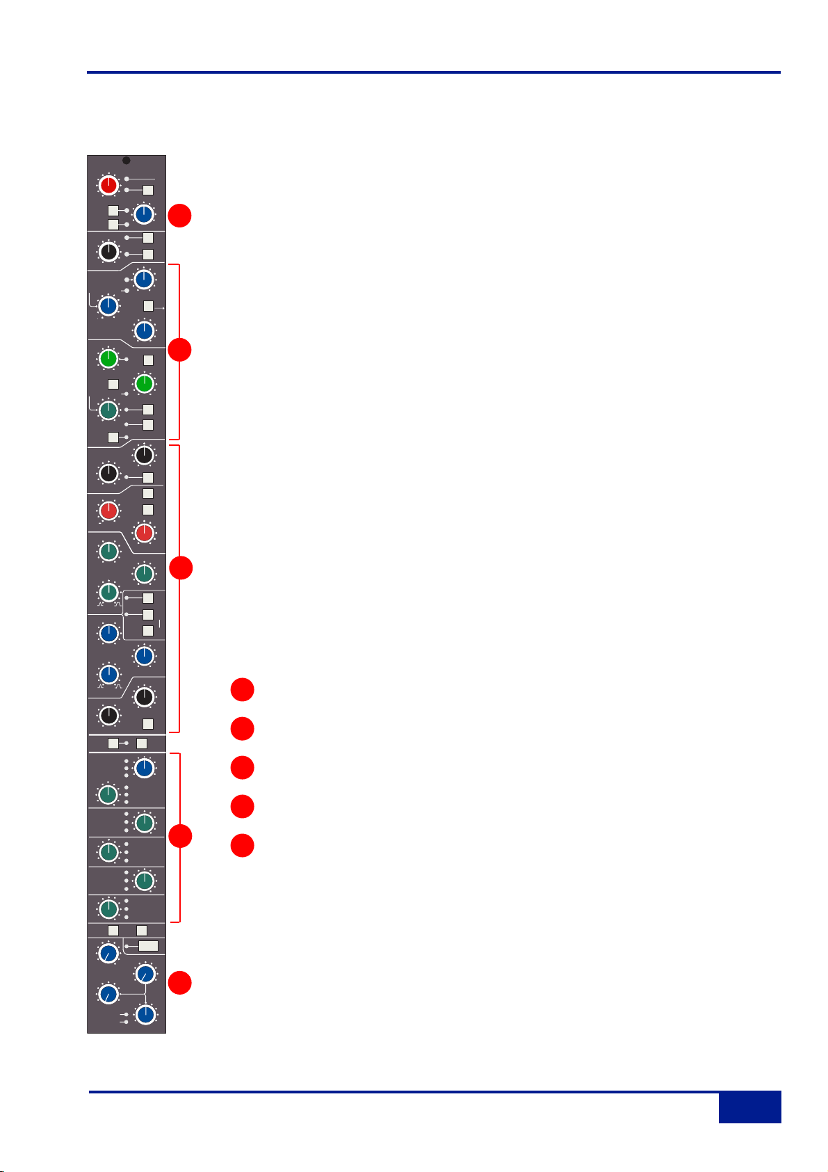
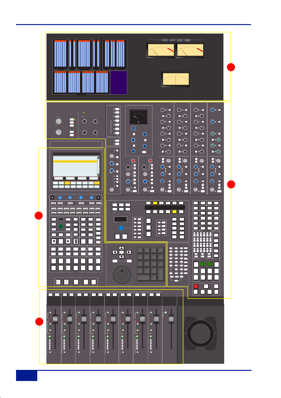
Channel Strip
Introduction
Duality’s Split Mode enables the channel processing to be easily applied to channel input
signals feeding the DAW record path or to the DAW returns. This provides the equivalent of inline operation but without the complexity of separate channel and monitor paths.
Users who are familiar with SSL’s range of in-line consoles will soon realise that the channel
strip faders can control virtual faders on the workstation as well as the channel signal path , in
many ways paralleling the large/small fader configuration of an in-line channel strip. This
provides an alternative to Split Mode working, with the DAW console handling the functions of
a monitor mixer.
The channel supports two input connections, the Monitor Input which is normally sourced
from the output of the DAW, and the Channel input which accepts variable level signals from
a microphone, DI box or other audio source. Three preamps are available for use with either
input: a unity gain line level buffer which is normally assigned to the DAW return, and a pair of
mic preamps sourced from the CHANNEL input XLR connector, one using SSL’s Super
Analogue direct coupled DC servo circuitry, and the other featuring SSL’s proprietary VHD™
(Variable Harmonic Drive) valve emulation gain stage. The channel output can route to 24
Track Busses, any one of three stereo Main Mix Busses (A, B and C) or all the Main Mix
Busses in 5.1 mode.
In addition to two Cue Stereo sends and four mono FX Sends, a dedicated Direct Output (CH
OP) is provided. Each channel has comprehensive routing for EQ and filter, dynamics, and
insert send/return points.
The channel strip can be divided into five distinct functional sections:
Channel input
Dynamics
EQ and filter
Cue Stereo and FX outputs
Channel output pan
Beneath the channel strips is a panel containing the ‘D-pot’ for DAW output or channel level
control. This area also houses cut and solo buttons for both fader and D-pot, and an electronic
scribble strip. Finally, below the ‘write-your-own’ scribble strip, each channel has a long-throw
(100mm) moving fader.
Above each bay of six channel strips, the TFT meter display provides a large range of useful
information on a per-channel basis, including audio and dynamics metering, processing order,
bus routing, automation bargraphs (optional) and Total Recall™ (optional).
5
4
3
2
1
1
2
3
4
5
Channel Strip
2-3
Duality Operator’s Manual
INPUT
+15
dB
PAD
DRV
IN
CH
-20
dB
COMPRESSOR
Push for Fst Att
141
RELEASE
GATE/EXP
0
RANGE
POST
EQ
Push for Fst Att
.1
REL/HOLD
DYN
IN
FILTERS
LF
60
30
20
Hz
HF
HMF
-
LMF
dB
LF
-
CH OP
AFL
CUE ST
FX1
FX2
FX3
FX4
SET EFX
/CUEB
LFE
LR
Focus
PAN TO TRK
48V
HI-Z
+75
2nd
0
0
dB
0
dB
Q
0
Q
0
dB
POST
CH OP
CH OP
CH OP
LCR
5.1
Ø
FILT
to
INP
+20
PK
20
1
RATIO
LINK
4
0
+10
- 20
THRESHOLD
KEY
EXP
40
0
+10
- 30
THRESHOLD
HOLD
4
S/Ch
LSTN
6
HF
9
4
30
100
3
OUT
kHZ
300
TO
S/Ch
500
G-EQ
BELL
+
5
10
2
15
1.5
22
KHz
+
2
3
5
1
7
.6
KHz
EQ
IN
INS
IN
POST
+
.
1.
6
0
.3
2.0
.2
KHz
220
15
0
400
60
40
600
Hz
BELL
+
SRC
SEL
ALT
LR
Cue B
EFX
ON
EFX
ON
CH OP
EFX
ON
EFX
ON
CH OP
EFX
ON
SPLIT
F
LR
SRC
SEL
R
3rd
DRIVE
Page 16
At your first introduction to the Duality console, you will immediately see that the channel strip controls are
presented in reassuringly familiar manner. The following pages describe each control in detail, with brief
coverage of the routing possibilities. See the start of this section for more on signal routing.
In the following descriptions, the connectors referred to are on the rear of each channel module,
unless stated otherwise.
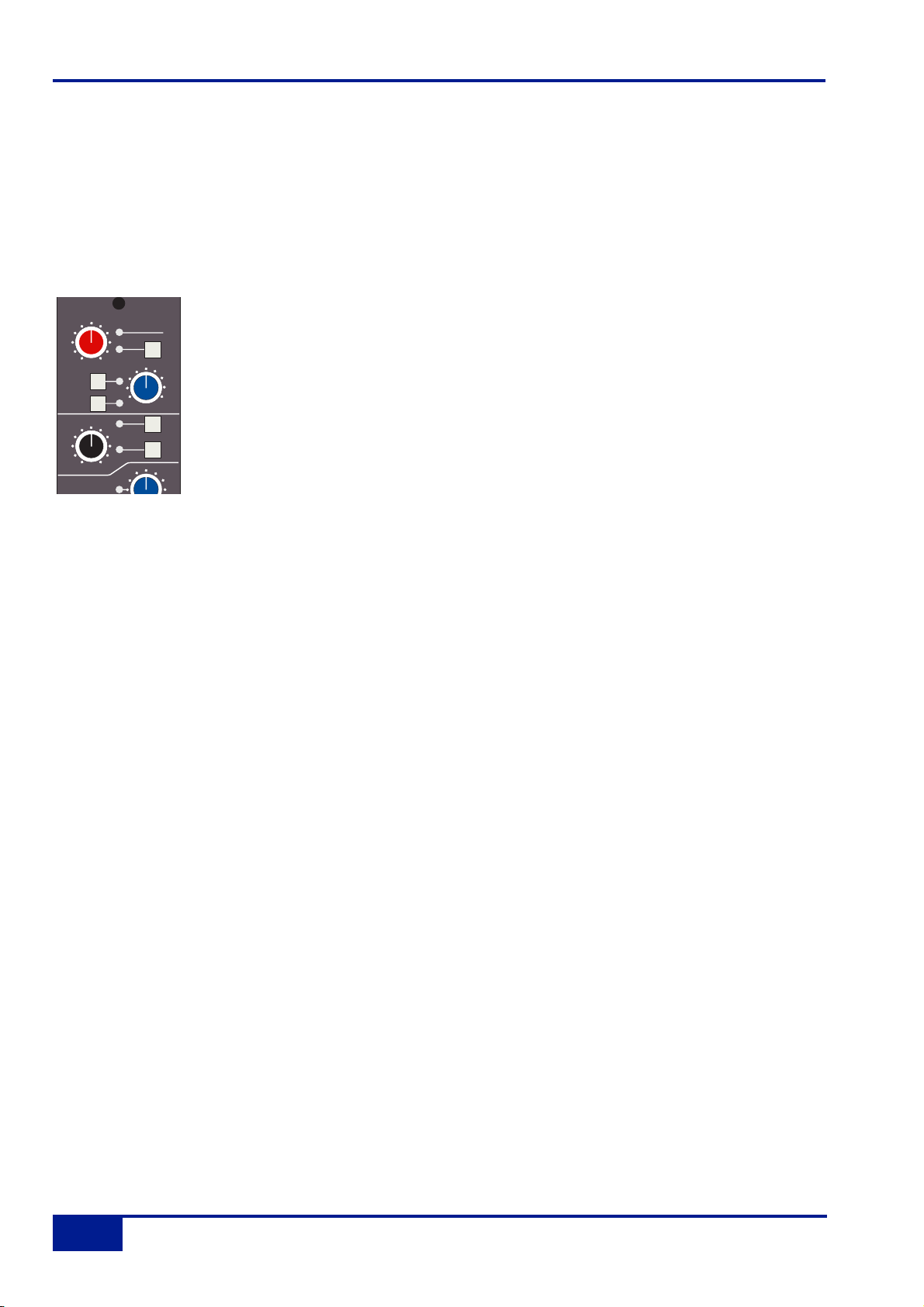
Channel Input Section
This provides two inputs, one dedicated as a line level DAW return (D-connector), the
other (XLR connector), is intended as a mic input but may be used for both mic or line
inputs. Normally the Mic Input feeds the variable gain INPUT amplifier, and the DAW
return feeds a unity gain line amp. However a centrally controlled INPUT FLIP function
reverses the input routing so that the DAW return can be processed by the variable gain
amplifier stage without the necessity for external patching.
The variable gain amplifier features two completely independent preamp stages. Both have electronically
balanced inputs with very different but complementary sonic qualities. The default preamp uses SSL's
acclaimed Super Analogue circuitry to provide an extremely low noise, extended bandwidth front end with the
minimum of signal colouration. Pressing the DRV IN button routes the input signal to a completely different
preamp featuring the SSL-developed VHD™ (Variable Harmonic Drive) circuitry. VHD emulates the
characteristics of a classic valve front end but with the option to tailor the harmonic mix when the preamp is
overdriven by adjusting the DRIVE pot. In conjunction with the 20dB PA D and Hi-Z input impedance option,
VHD can provide subtle valve style warmth to a mic signal or aggressive tonal shaping to existing DAW tracks.
However, be aware that, due to differences in the mic amp topology, exact matching of gains is not possible.
Note that many of the signal routing functions on a channel strip are also available
on the central routing panel, and some are only available on the central routing panel
The post input stage CH (channel) control provides final ±20dB gain trim (for reducing the level when the input
section is being abused for creative reasons) and polarity inversion (Ø), for the centrally selected channel
source. Available input options are the output of the mic input preamp (MIC), the balanced line level DAW
return (LINE), or the channel’s associated track bus for patch free subgroups (BUS). In the latter case, the
channel input is replaced by the output of one of the 24 Track Mix busses where Bus N feeds the input of
Channel N, N+24, N+48 etc.
FILT to INP locks the high and low pass filters to the channel source. +48V phantom power for mic inputs is
selected on the central routing panel.
Console Operator’s Guide
2-4
Duality Operator’s Manual
INPUT
+15
dB
PAD
DRV
IN
CH
0
-20
dB
COMPRESSOR
+75
+20
48V
HI-Z
2nd
DRIVE
3rd
Ø
FILT
to
INP
Page 17
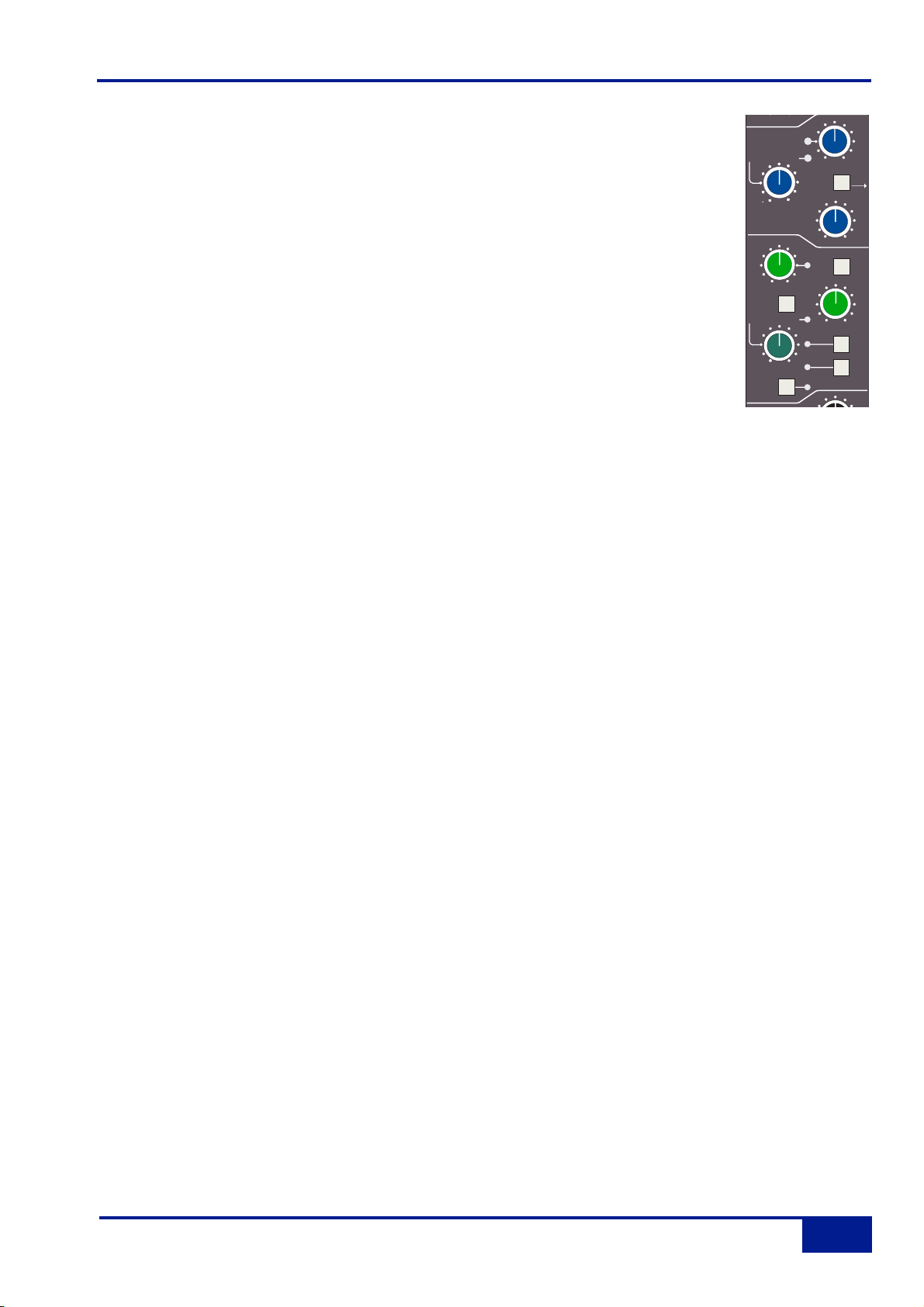
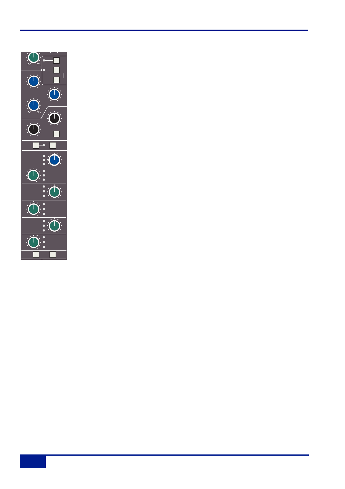
Dynamics Section
The Dynamics section contains a compressor section identical to that of the 9000K
series and also found in SSL's Logic FX range of outboard processing units. In normal
use, the compressor’s true r.m.s. side chain and over-easy soft ratio function provide a
very transparent compression action even with large amounts of gain reduction. The fast
attack option offers the classic SSL compressor sound normally associated with its use
on drum and percussion sources. Selecting Peak (PK) mode defeats the over-easy soft
ratio, modifies the release curve and attack times, and unleashes a far more aggressive
sounding compressor ideal for more radical sonic shaping.
The Gate/Expander section is a new variant of SSL’s classic 4000 series three-control
design. It features the choice of a steep gate or gentle expander slope, with optional fast
attack. The new ‘Hold’ (HOLD) option flips the variable release (REL) control to function as
a variable hold-off time with a fixed release curve.
The complete section is switched in or out of circuit using the DYN IN button (see also Central Routing
Control). When the dynamics section is in circuit, the DYN box on the channel TFT display is highlighted.
Individual controls act as follows:
Compressor
RATIO – When turned to 1:1, the compressor section is inactive. Turning the control clockwise increases the
compression ratio until it reaches a true limit mode at the fully clockwise position. Pressing the RATIO knob
switches the compressor to peak sensing, and replaces the ’over easy’ characteristic with a hard knee,
providing an alternative voicing for some instruments. The PK LED lights to indicate that this option has been
selected.
THRESHOLD – Whenever a signal exceeds the level set by this control, the compressor will start to act at the
ratio set by the RATIO control. This control, in conjunction with the Ratio setting, provides automatic make-up
gain, so as you lower the threshold and introduce more compression, the output level is increased, maintaining
a consistent output level.
RELEASE – Sets the time constant (speed) with which the compressor returns to normal gain settings once
the signal has fallen below the compressor threshold. This control also incorporates a push-push switch which
selects a very fast attack time as an alternative to the standard time constant.
Gate/Expander
This section can act as a Gate or as a 2:1 Expander when the RANGE pot is pressed. A red LED indicates that
Expand mode has been selected.
RANGE – Determines the depth of gating or expansion. When turned fully anticlockwise (Range = 0), the
section is inactive. When turned fully clockwise, an attenuation range of 40dB can be obtained.
20
+20
Dynamics Section
2-5
Duality Operator’s Manual
dB
COMPRESSOR
Push for Fst Att
PK
4
141
RELEASE
GATE/EXP
+10
POST
EQ
IN
0
RANGE
.1
REL/HOLD
EXP
40
4
Push for Fst Att
DYN
1
RATIO
0
THRESHOLD
- 30
THRESHOLD
9
20
LINK
- 20
0
+10
HOLD
LSTN
6
KEY
S/Ch
HF
Page 18

THRESHOLD – Variable hysteresis is incorporated in the Threshold circuitry. For any given ‘open’ setting, the
Expander/Gate will have a lower ‘close’ threshold to prevent ‘hunting’ artifacts. The hysteresis value is
automatically increased as the Threshold is lowered. This is very useful in music recording as it allows
instruments to decay below the open threshold before gating or expansion takes place.
REL/HOLD – This determines the time constant (speed), variable from 0.1- 4 seconds, at which the
Gate/Expander reduces the signal level once it has passed below the threshold. Note that this control interacts
with the Range control. This control also incorporates a switch which, when pushed, provides a fast attack time
(100µs per 40db), instead of the normal linear attack time of 1.5ms per 40dB. The attack time is the time taken
for the Expander/Gate to ‘recover’ once the signal level is above the threshold. When gating signals with a
steep rising edge, such as drums, a slow attack may effectively mask the initial THWACK, so you should be
aware of this when selecting the appropriate attack time.
HOLD – When this button is pressed, the release time is fixed at 150ms but the hold time can be varied
between 0 and 4 seconds by adjusting the REL/HOLD pot.
The LINK button in the compressor section links the sidechain signal of that unit to the sidechain of the next
dynamics section to the right. When two dynamics sections are linked, the control voltages of each section sum
together, so that whichever section has the most gain reduction will control the other section.
Don’t try to link two gates using the LINK button when you want the signal on one to open the other. If you
need to achieve this effect, take a keying signal from one section to trigger the other. The easiest way to do this
is by patching from the insert send of the ‘source’ channel into the Key input (see below) of the ‘destination’
channel, and selecting the KEY button on this channel.
The KEY button feeds whatever signal is present on a channel’s Key input (D-connector) into the sidechain
input of that channel’s dynamics section. Pressing S/Ch LSTN routes the sidechain signal to the console’s PFL
bus. This simplifies the set up when either an external key input or the filters to side chain option is in use.
POST EQ (not surprisingly) places the dynamics section post the EQ section (see also Central Dynamics
Control below.
Note that when the dynamics section is not in circuit, its sidechain input is also bypassed.
Signal processing order is graphically displayed on the channel TFT screen
Console Operator’s Guide
2-6
Duality Operator’s Manual
Page 19
Central Dynamics Control
The centre section master routing panel replicates the dynamics POST EQ function for sweet spot control and
multiple channel operation using the SELECT/TO range keys.
Dynamics Section Metering
The TFT screen above each bay of six channel strips is used to display a wide variety of relevant information.
In its default Channel mode, as well as channel output metering (see later) a display of dynamics section gain
processing is shown, in the form of two columns of indicators – yellow and red for the compressor, green for
the gate/expander. See Channel Metering for more information.
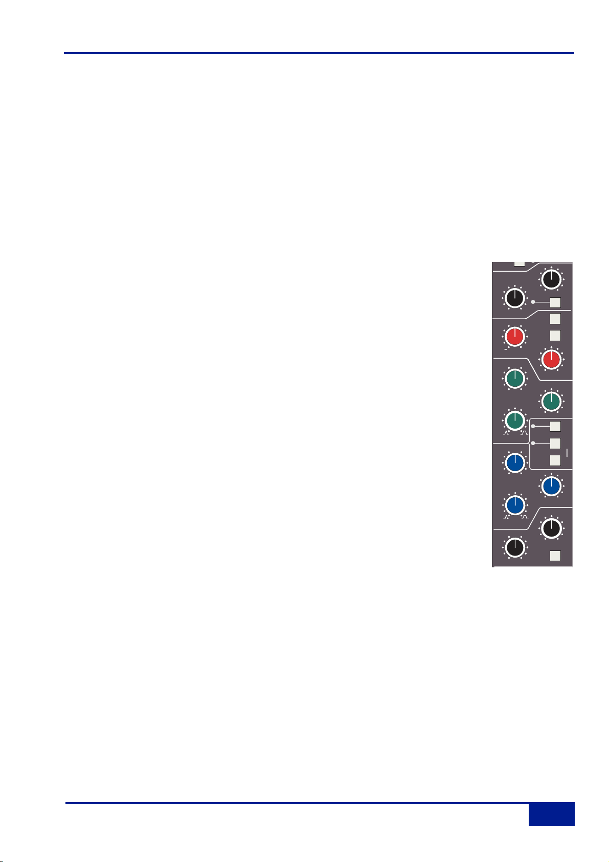
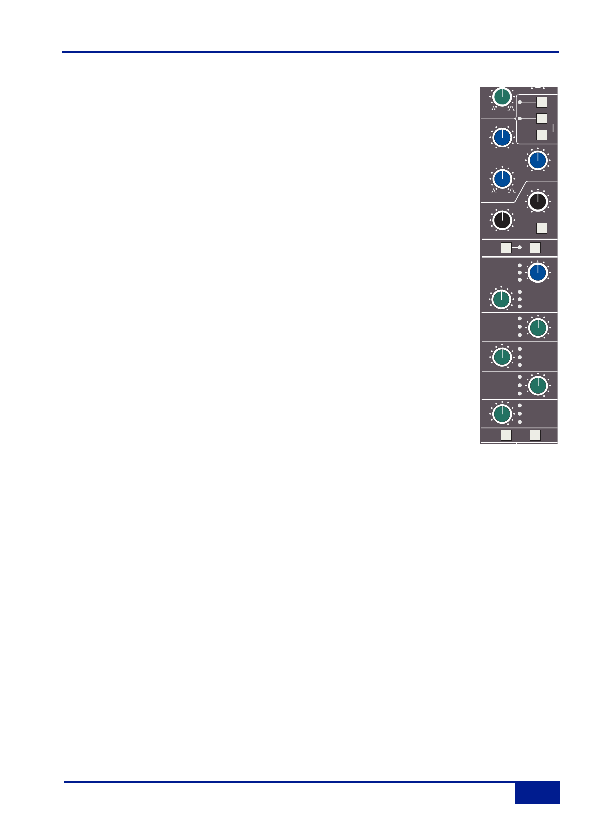
Filters
These comprise a 3rd Order 18dB/Octave high pass filter (HF) and a 2nd Order
12dB/Octave low pass filter (LF). Each filter is out of circuit when the control is fully
anticlockwise. When the filter is in circuit, the FILTER box on the channel TFT display is
highlighted.
Normally, the filters follow the EQ section in the signal chain but the FILT to INP button
in the input section of the channel strip places the filters directly after the channel input.
This function is also available on the central routing panel. Pressing TO S/ch routes the
filter section to the dynamics sidechain.
Signal processing order is graphically displayed on the channel TFT screen
Equaliser
This is a four band parametric equaliser based on SSL’s classic 'Black Knob' EQ, which
was developed for the original SL4000E series console. Selecting the G-EQ button
introduces steeper shelving curves with a controlled amount of undershoot at the
turnover frequency, together with the classic gain/bandwidth interaction for the mid band
sections that was a key characteristic of the original G-Series EQ.
The individual bands function as follows: HF high frequency shelving equaliser
switchable to fixed Q parametric (BELL); HMF high frequency parametric mid band
equaliser; LMF low frequency parametric mid band equaliser; LF low frequency shelving
equaliser switchable to fixed Q parametric (BELL). The EQ IN button (located next to the
insert buttons) routes the channel signal through the EQ and filter section. When in
circuit, the EQ box on the channel TFT display is highlighted. See also Central Routing
Control.
L
T
Q
Filters and EQ
2-7
Duality Operator’s Manual
IN
FILTERS
LF
30
HF
HMF
LMF
LF
6
HF
9
4
60
20
30
100
300
500
Hz
0
+
dB
0
+
dB
Q
0
+
dB
Q
0
-
+
dB
3
OUT
kHZ
TO
S/Ch
G-E
BEL
5
10
2
15
1.5
22
KHz
2
3
5
1
7
.6
KHz
EQ
IN
INS
IN
POS
.
1.
6
0
.3
2.0
.2
KHz
220
15
0
60
400
40
600
Hz
BELL
Page 20
Insert
The INS IN button routes the channel signal via balanced insert send and return points,
available on the rear of the console (D-connectors). The insert defaults to the channel
input (post the input trim); POST cycles the insert position through two alternative
locations in the processing path: post EQ or post Dynamics; the centre section master
routing panel provides individual INS POST EQ and INS POST DYN buttons. When the
insert is active, the INSERT box on the channel TFT is highlighted.
Signal processing order is graphically displayed on the channel TFT screen
Channel Output (CHOP)
The Channel Output (D-connector) is normally used to feed the DAW input. The default
signal is a post channel fader feed, but the SRC SEL button can be used to select
alternative sources: pre channel fader (pre the SPLIT point – see below), the channel
input (also pre the SPLIT point), or an active EFX send (see below). Each selection is
graphically displayed on the channel TFT screen (see Channel Metering for more
information). When either the channel input or pre fader source is selected, the SPLIT
button activates the Split Monitoring function and routes the DAW return into the channel
signal path post the split point (see below).
Use the associated AFL button to monitor the channel output source as you toggle
through the options with the SRC SEL button. The central routing panel has single button
selection of the four channel output sources: INPUT, PRE FADE, POST FADE, EFX.
Signal Processor Routing
By now you will have realised that Duality features extremely flexible signal processor routing within each
channel. In addition, the channel output (CHOP) can be sourced from a number of different points in the
channel. Furthermore, the SPLIT function effectively offers two signal paths in one channel strip. A useful
graphic display on the channel bay TFT (see Channel Metering) makes clear, at any time, the current
arrangement for any channel.
6
7
Console Operator’s Guide
2-8
Duality Operator’s Manual
LMF
LF
CH OP
AFL
CUE ST
FX1
FX2
FX3
FX4
SET EFX
/CUEB
.
KHz
Q
0
+
-
-
.
dB
6
.3
.2
KHz
15
Q
0
60
0
40
Hz
+
dB
POST
CH OP
ALT
LR
Cue B
EFX
ON
CH OP
EFX
ON
CH OP
EFX
ON
CH OP
EFX
ON
CH OP
EFX
ON
POST
1.
0
2.0
220
600
BELL
EQ
IN
INS
IN
400
SRC
SEL
SRC
SEL
Page 21
Channel Sends
Each channel has two stereo and four mono sends that can be used for a number of
different purposes: headphone feeds, FX sends, etc. The stereo cues can even be used
to provide an additional line input to the mix.
Cue Stereo
Normally, the stereo cue sources a pre channel fader signal, which routes to the console’s
Cue A bus. This in turn can be picked up in the centre section and used as a foldback
source (see Cue/FX Master Controls). Press and hold down the SRC SEL button (at the
base of the Channel Sends section) then press the stereo cue gain pot to toggle the source
through post fader channel feed (POST), channel direct output (CHOP) or the alternative
channel input (ALT), as indicated by the LEDs adjacent to the stereo cue gain pot. The ALT
selection is defined as whichever input is not assigned to the main channel path (when
SPLIT mode is not active), and allows the stereo cue to be used as an additional input.
Likewise, select the stereo cue output to Cue B by holding down the SET EFX/ CUE B
button then pressing the stereo cue gain pot; this toggles the selection through Cue B, EFX
and Cue A (off).
Master controls for the Cue A and B busses can be found in the centre section.
Pan your mono source across the stereo cue bus outputs with the LR pan control. The
stereo cue send is turned on/off by means of a push-push switch mounted on the send level
control.
FX Sends
The four mono FX Sends are normally sourced post channel fader. They may, however, be sourced from the
channel output (CHOP) by pressing and holding down the SRC SEL button (at the base of the Channel Sends
section) then pressing the required FX gain pot to toggle the selection on/off.
Each FX level pot is fitted with a push-push on/off switch; ‘on’ is indicated by a LED beside the pot. Master controls
for each FX bus can be found in the centre section.
Selecting an FX output to the EFX system (press and hold the SET EFX/ CUE B button then press the required FX
or Cue Stereo gain pot) allows a single send to be isolated from its associated bus and to be used as source for
either the Track Busses (selected in the centre section), or the channel output — CHOP (selected locally or in the
centre section). This enables additional independent effects send or headphone mixes to be easily generated.
Logic interlocks prevent feedback paths by disallowing the EFX function on a send sourced from the channel output
if EFX to channel output is active.
See Cue/FX Master Controls for more on EFX routing.
6
7
T
0
Channel Sends
2-9
Duality Operator’s Manual
.
KHz
EQ
LMF
LF
CH OP
AFL
CUE ST
FX1
FX2
FX3
FX4
SET EFX
/CUEB
Q
0
+
dB
Q
0
-
+
dB
POST
CH OP
ALT
CH OP
EFX
ON
CH OP
EFX
ON
.3
.2
15
0
60
40
Cue B
EFX
ON
CH OP
EFX
ON
CH OP
EFX
ON
.
6
KHz
Hz
LR
POS
1.
0
2.0
220
600
BELL
INS
SRC
SEL
SRC
SEL
IN
IN
40
Page 22

Split Mode
When the channel output (DAW input) is sourced from either the channel input or pre the
channel fader, SPLIT offers a new approach to in-line tracking on an analogue console by
returning the DAW output back into the channel path just after the channel output pick off
point. By using INPUT or PRE FADE as the channel output source, clean or processed
signals are routed to the DAW input, with the option to use the remaining channel processing
and routing to monitor the DAW return in the analogue domain.
The effect of SPLIT is graphically illustrated on the channel TFT (see Channel Metering for more information).
Note that SPLIT is disabled if CHOP is sourced from POST FADE or EFX,
or if the Line Amp is selected as the channel input.
Channel Pan
At the bottom of the channel strip is a fully featured 5.1 panning section for both the Main Mix busses as well
as the 24 Track Busses. With the most complete implementation found on any analogue console, the feature
set includes a dedicated LFE send and a fully variable ‘Focus’ control to alter the phantom/hard centre mix for
signals located in the front channels.
The default arrangement is for stereo panning to three pairs of Main Mix busses – A, B and C. The 24 Track
Busses normally pick up the mono post fader channel output. On the centre section routing panel, selecting
PAN TO TRK routes the LR pan outputs to odd/even pairs of Track Busses. Selecting 5.1 PAN enables the full
6-channel panning options for both the Main Mix busses and the Track Busses, if PAN TO TRK is also
selected. Local LEDs in each panning section indicate whether that channel has been selected to either of
these two modes. When 5.1 panning is not enabled, only the LR (Left/Right) pan control is active.
If the centre section function EFX TO TRK is selected, this replaces the normal feed to the Track Busses and
defeats 5.1 panning to the busses.
The channel panning section features XY style 5.1 panning via LR (Left/Right) and FR (Front/Rear) controls
with additional LFE and Focus functions. The LFE control feeds a variable amount of the channel output to a
dedicated LFE (subwoofer) bus (see more on this in the Centre Section).
The Focus control alters the proportion of input signal fed to the front Left/Right busses and the Centre bus,
enabling channel signals to be focussed from a ‘hard’ centre, all the way through to a true phantom centre. As
the Focus knob is rotated clockwise from the LR position, a centrally panned signal is progressively attenuated
in the left and right busses, while the gain to the centre channel is increased. When fully clockwise, the LR pan
pot becomes a three-channel discrete LCR panner. As the Focus control is returned to the LR position,
variable amounts of divergence are introduced so that, at the 12 o’clock position, signal is present in the three
front channels at equal level. As you continue to turn before 12 o’clock, the centre channel is then
progressively reduced, leaving only the phantom (Left + Right) centre image at the fully anticlockwise position.
Console Operator’s Guide
2-10
Duality Operator’s Manual
SPLIT
LFE
LR
Focus
PAN TO TRK
F
LCR
5.1
LR
R
Page 23
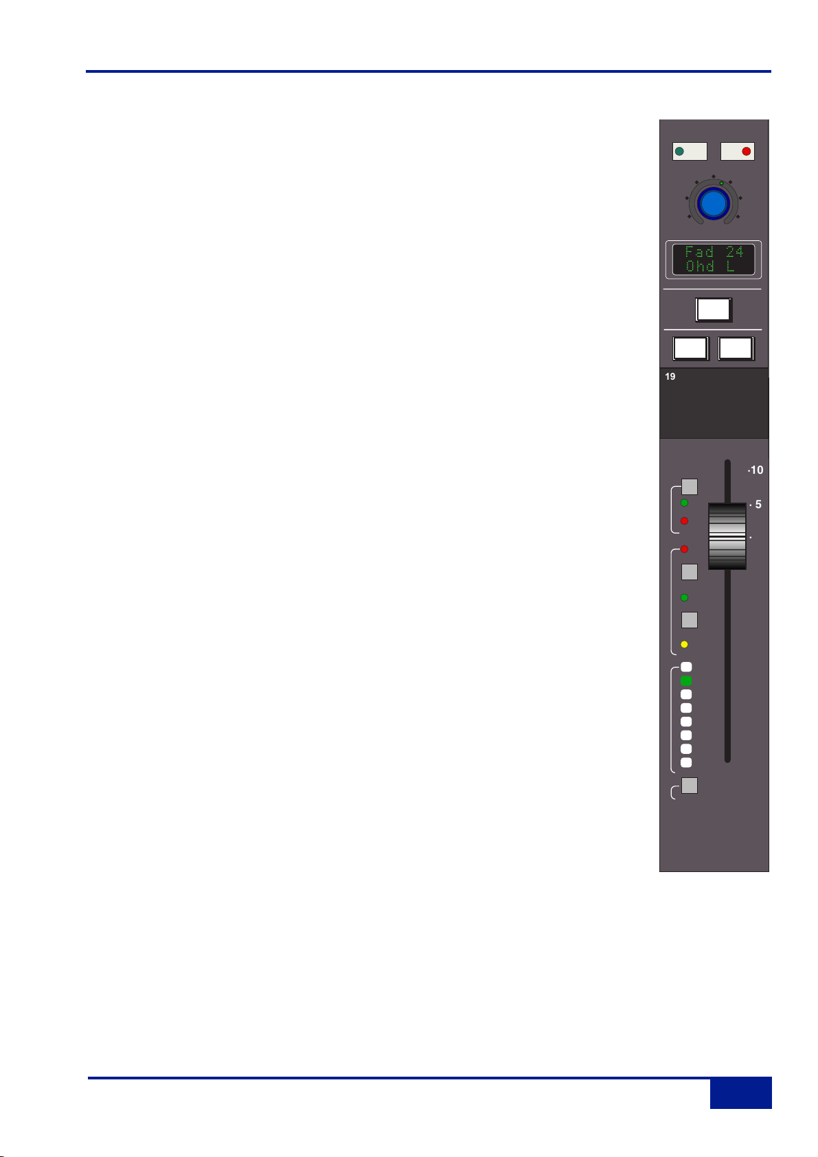
D-pot and DAW Control
Below the channel strips is a 12-wide panel containing a rotary encoder known as the
D-pot, together with its integral momentary switch mounted on the encoder shaft. This is
used to adjust the currently assigned DAW parameter or the analogue channel level;
D-pot functions are assigned from the centre section, and indicated in the D-pot’s
associated two line display.
The CUT and SOLO buttons above the encoder are used when the encoder is
controlling the DAW or Duality channel gain.
The electronic scribble strip displays the channel name, the name of a DAW track,
selected DAW send, or I/O data according to the function currently assigned on the
Master Control Panel (see Section 3). When the rotary control and the fader swap roles
for gain control, entries in the scribble strip also flip.
The SEL button operates the DAW ‘Selected Channel’ function. This function can be reassigned from the centre section, to track arm a selected DAW channel or assign the
‘plug-in’ editor (Pro Tools only). Tallies in the channel meter display Record Ready and
Edit status regardless of whether the console is in ‘DAW Focus Mode’ (see Section 3 for
more details).
Channel Cut and Solo
The CUT and SOLO buttons above the traditional scribble strip are used when a gain
function is assigned to the channel fader. SOLO is not active if a function other than the
channel level (DAW or console) is being controlled.
Channel Fader
The 100mm moving fader controls the analogue channel, or assigned DAW track, or the
DAW send level when the centre section ‘flip’ function is active (Pro Tools/HUI and MCU
interfaced DAWs), plus Plug-In parameters when using a MCU compatible DAW. The
required function is selected via the Master Control Panel (see Section 3 for details).
The fader button, and associated LEDs are used in conjunction with the DAW
automation (HUI interface only) or the optional Duality automation and ‘multi-operator’
Total Recall systems. The play and match buttons are used only with Duality
automation. See Sections 4 and 5 for more details.
The select button at the foot of the fader is used to select that channel to the central
routing panel, and for fader grouping (see below).
DAW Control and Fader
2-11
Duality Operator’s Manual
SOLO
CUT
Fad 24
Ohd L
SOLO
19
fader
rec
play
match
switch
1
2
3
4
5
6
7
8
group
select
SEL
CUT
·10
· 5
· 0
· 5
· 10
· 20
· 30
· 40
· 50
· ∞
Page 24
Fader Grouping
The console’s centre section is fitted with eight group control faders that offer VCA-style grouping control
(servo, ie. moving fader, grouping will available in a future software update). To assign channel faders to a
group, simply press the select buttons of the channels you want to include in the group followed by the group
button at the foot of the required group fader. The group display on each fader will reflect your choice (the fader
in the illustration above is being controlled by group fader 2). See Control Group Faders for more information.
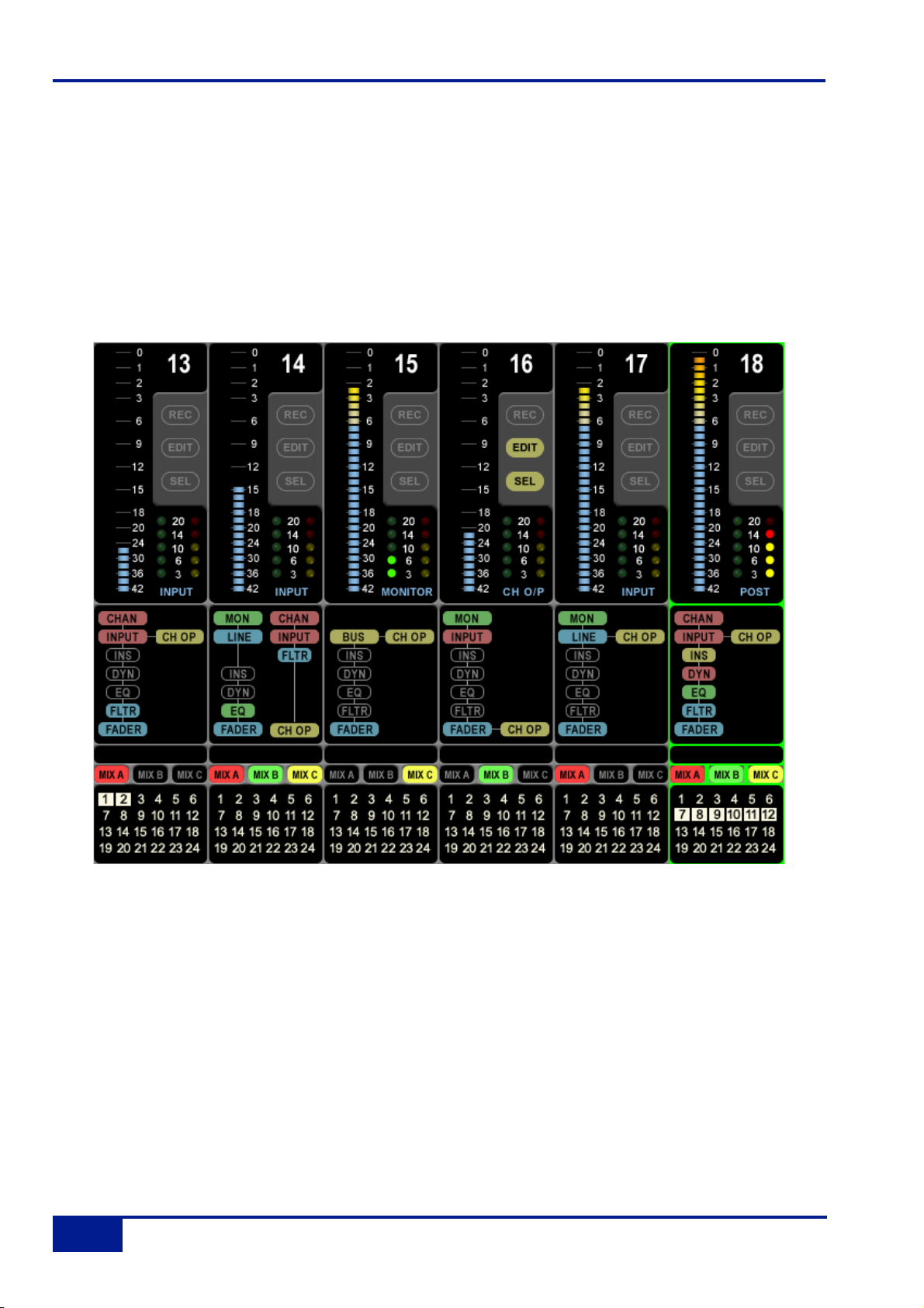
The Channel TFT Screen
The TFT screen fitted above each channel bay (see above) is normally used to display a number of channel
related parameters for the six channels in that bay. When Total Recall is in use, the screen flips automatically to
display the control positions for a single, selectable, channel (see Section 4 for more details).
Channel Routing
At the bottom of the channel display a clear indication is provided of each channel’s routing to Main Mix busses
A, B and C and the 24 Track busses. Note that the Mix Busses are colour coded, and this same coding is also
utilised in the centre section.
Console Operator’s Guide
2-12
Duality Operator’s Manual
Page 25

Channel Processing Order
The section above the routing indicators displays the order of channel processing for both signal paths in each
channel (including the channel inputs, the channel fader and the channel output) as well as providing an
indication of which processing element is actually in circuit. Once again, colour coding is used for ease of
recognition.
Channel Metering
A single peak meter indicates either analogue channel signals or DAW levels, according to selection of the
Console/DAW ‘Focus’ button (see Section 3 for more on this). The standard scale is +24dB for 0dBFS (top of
the scale). A peak hold option is available for channel and centre section meters via the centre section
METERS setup menu. A legend below the Dynamics section indicators (see below) confirms the currently
selected meter point for that channel, as set on the central routing.
In addition to the expected channel metering, two columns of five ‘LEDs’ give an indication of channel
gate/expander activity (green ‘LEDs’) and compressor activity (yellow and red ‘LEDs’).
DAW Status Indicators
To the right of each channel meter are three indicators that provide feedback of the current DAW status of that
channel. SEL confirms that channel is currently the ‘selected channel’. REC indicates the Record Ready status
of the associated DAW track, and EDIT shows if the DAW channel associated with that channel strip is
currently assigned to the plug-in editor (Pro Tools only). See Section 3 for more details. Note that Record
Ready and Edit status will be indicated regardless of whether the console is in ‘DAW Focus Mode’ or not.
Channel TFT Screen
2-13
Duality Operator’s Manual
Page 26
Console Operator’s Guide
2-14
Duality Operator’s Manual
1
2
4
3
CLIP
CLIP
CLIP
0
2
4
6
8
10
14
20
30
40
50
60
L C R LS RS LF L R
5.1 MIX ST MIX
CLIP
0
2
4
6
8
10
14
20
30
40
1 2 3 4 5 6 7 8 9 10 11 12 13 14 15 16 17 18 19 20 21 22 23 24
0
2
4
6
8
10
14
20
30
40
50
60
CLIP
0
2
4
6
8
10
14
20
30
40
CLIP
0
0
2
2
4
4
6
6
8
8
10
10
14
14
20
20
30
30
40
40
50
50
60
60
L C R LS RS LF L R
BUSSES 1-24
FOLLOW MON SOLO
CLIP
0
2
4
6
8
10
14
20
30
40
MON
ST MIX
MIX A
CLIP
CLIP
CLIP
CLIP
CLIP
0
0
0
2
2
4
4
6
6
8
8
10
10
14
14
20
20
30
30
40
40
50
50
60
60
CLIP
0
2
4
6
8
10
14
20
30
40
0
2
2
4
4
6
6
8
8
10
10
14
14
20
20
30
30
40
40
50
50
60
60
L R
CUE A
CLIP
0
2
4
6
8
10
14
20
30
40
Logic
0
2
4
6
8
10
14
20
30
40
50
60
L R
1 2 3 4
CUE B
FX SEND
Solid
State
CLIP
0
2
4
6
8
10
14
20
30
40
50
60
LEFT RIGHT
SOLO
PHASE
MIX REASSIGN
CUE
A
TRACKS
LFE CHANNEL
LFE
FILTER
STEREO MIX
∞
∞
SURROUND
∞
CENTRE
STEREO
∞
LEVEL
CUE
B
EXT B
16
712
1318
1924
MAIN
MIX
80H
Z
LFE
MIX 2
MIX 2
TO
MIX
+6
SLLLFE SR
MONITOR MUTE/SOLO
MONITOR LEVEL
DIM
SCRU
B
INP
PRE
ON
ON
ON
MIX
A
MIX
B
MIX
C
INS
00.0
ZOOM/
0
-20 +20
THRESHOLD
LFE
TO S/C
13
.3
.1
ATTACK - mS
SRND
TO S/C
3
2
1.5
RATIO
F/BACK A
HF
LF
+0+
d
B
∞
MIX 1
MIX 2
∞
MIX 2
+6
∞
LEVEL
R
C
CUT
SEL
SHUTTLE
+15 -15 +4 +12
OSCILLATOR
TRAC
CAL
LEVEL
440 1K
3K
220
10K
100
PINK ON
15K
48
OSC ON
FREQ
00:02:12:23 Mix Enabled
New Mix
Mix Pass 1
Mix Pass 2 >> 1
Mix Pass 3 >> 2
COMMS
K
RE
C
MI
X
∞
Listen
∞
Talkback Out
∞
Slate
∞
TB to Foldback
List Mix Save/Load Delete Confirm
Proj
T
Aut
Lnks DawMis
R
o
Moff
TLockTrim Snap AT Match
CHANNEL
SEND
AUX2
PAN
Push to Flip
RDY
EDIT
CHANNEL
INPUT
OUTPUT
ASSIGN
MUTE
PRE/POST
BYPASS
DEFAULT
SEL
SUSPEND
AUD IN OUTPRE POST
RTZ END
TRIM
JOIN
MOTORS
REVISE
OFF
Q
LOOP
PUNCH
TRIM
END
AUTO
SNAP
T/OVER
LOK
DISCARD
REPLAY
AUTOMATION
SSL
c
Play
CS
UNDO
SAVE
ALT
ESC
SHIFT
CTRL
AUTO
ON
LINE
STATUS
ENTER
TRANS
OPTION
MEM
ALT
MIX
RDY
ALL
EDIT
SOLO
ISO
GROUP
ALL
CANCEL
STOP RECORDPLAY
TRANSPOR
T
SOLO CUT SOLO CUT SOLO CUT SOLO CUT SOLO CUT SOLO CUT SOLO CUT SOLO CUT
OLO OLO OLO OLO
GROUP 1 GROUP 2 GROUP 3 GROUP 4 GROUP 5 GROUP 6 GROUP 7 GROUP 8
GROUP 1 GROUP 2 GROUP 3 GROUP 4 GROUP 5 GROUP 6 GROUP 7 GROUP 8
UT
UTUT
UT
UTUT
OLO
UT
UTUT
OLO
COMPRESSOR
12
8
16
4
20
dB
COMPRESSION
SL978
0
+
MAKE-UP
10
30
S/C
.3.61.2
.1
AUTO
4
RELEASE - S
5
10
IN
F/BACK B
HF
LF
ST
MON
+0+
EXT B
d
B
MIX B
CUE
∞
A
MIX 1
MIX 2
CUE
∞
B
MIX 2
CU
T
+6
∞
LEVEL
EXTA EXTB METERS
0
+
d
B
ST
MON
EXT B
MIX B
CUE
A
ST MIX
CUE
B
CU
T
AF
L
0
+
d
B
ST MIX
AF
L
DVD SACD CD MD SNET SUM
DIM
ALT
5.1
AFL
PFL
MINI
A
SI
F
MINI
H/P
B
MIN
I
LS SELECT
/
=
CLR
7
89
45
6
1
23
.
0
UT
UTUT
OLO
OLO
TRACK BUS
MASTERS
+10
∞
BUS
1
AF
∞
L
+10
∞
BUS 3
AF
L
+10
∞
BUS
5
AF
L
+10
∞
BUS
7
AF
L
ST RET 1
FB A
FB B
LRC
FOCUS
FULL
MONO
WIDTH
LR
BALANCE
+6
∞
LEVEL
MONITOR
AFL/
OPTIONS
PFL
MO
N
FB A
FB B
CUT
PHONES
*
-
+
E
N
T
E
R
UT
UTUT
MASTER
AF
L
+10
BUS
2
AF
L
∞
+10
BUS
4
AF
L
∞
+10
BUS
6
AF
L
∞
+10
BUS
8
∞
STUDIO
ST
PAN
MIX A
MIX B
MIX C
FB
PAN
MONO
CUT
L
CUT
R
AFL/SEL
EXTA
EXTB
STEREO
MIX A MIX B MIX C
SUM SUM SUM
POST POST POST
+10dB
FADER
TRACK BUS
MASTERS
+10
∞
BUS
9
AF
L
+10
∞
BUS 11
AF
L
+10
∞
BUS
13
AF
L
+10
∞
BUS
15
AF
L
ST RET 2
FB A
FB B
LRC
FOCUS
FULL
MONO
WIDTH
LR
BALANCE
+6
∞
LEVEL
MISC
SUM
SOLO
SOLO
CLEAR
Ø
STEREO
MIX
MIX A
MONO
INSERTINSERTINSERT
COMPCOMPCOMP
+10dB
+10dB
FADER
FADER
TO ATO A
AFLAFLAFL
5.1 MIX
AF
L
+10
∞
BUS
10
AF
L
∞
+10
BUS
12
AF
L
∞
+10
BUS
14
AF
L
∞
+10
BUS
16
∞
STUDIO
MIX A
MIX B
MIX C
AFL/SEL
TRACK BUS
MASTERS
+10
∞
BUS
17
AF
L
+10
∞
BUS 19
AF
L
+10
∞
BUS
21
AF
L
+10
∞
BUS
23
AF
L
ST RET 3
FB A
FB B
ST
PAN
LRC
FOCUS
FB
PAN
FULL
MONO
WIDTH
MONO
LR
BALANCE
CUT
L
CUT
R
+6
∞
LEVEL
INPUT
FLIP
MIC
DYN POSTEQINS POST EQINS POST
INSERT INEQ
INPUT
INPUT
123456
78910111
1
3141516
19202122232
MIX A
–
SET SELECT
CLEAR
SLATE
TB
ALL
∞
∞
∞
∞
∞
STUDIO
MIX A
MIX B
MIX C
INPUT
AF
L
+10
BUS
18
AF
L
+10
BUS
20
AF
L
+10
BUS
22
AF
L
+10
BUS
24
ST
PAN
FB
PAN
MONO
CUT
L
CUT
R
AFL/SEL
+48V
CHANNEL IN
PROCESSING ORDER
IN
PROCESSING IN/OUT
PRE
FADE
CHANNEL OUTPUT
MON
RETURN
CHANNEL METERS
MIX B MIX C
ROUTING
FRO
M
ALL
CHANNEL SELECT
LISTEN
F/B A
COMMUNICATIONS
AUX BUS
MASTERS
AF
+10
∞
L
ST CUE
A
AF
+10
∞
L
ST CUE
B
AF
+10
∞
L
FX
1
AF
+10
∞
L
FX
2
AF
+10
∞
L
FX
3
AF
+10
∞
L
FX
4
ST RET 4
FB A
FB B
∞
STUDIO
ST
PAN
LRC
MIX A
FOCUS
MIX B
MIX C
FB
PAN
FULL
MONO
WIDTH
MONO
LR
BALANCE
CUT
L
CUT
R
+6
∞
LEVEL
AFL/SEL
SOLO
ISOLATE
MISC
SPLIT
BUSLINE
FILTER
TO INPUT
DYN
POST
EFX
FADE
POST
CHAN
FADE
OUT
2
EFX
TO TRK
171
8
PAN
TO TRK
4
5.1
PAN
INC
ROUTE
PAN MODEBUS
+
T
O
SET
TO
AUX
UNDO
RED
LIGHT
EXT
F/B B
T/B
·10
· 5
fader
· 0
rec
· 5
play
· 10
match
· 20
switch
1
· 30
2
3
· 40
4
5
· 50
6
7
· ∞
8
group
·10
· 5
fader
· 0
rec
· 5
play
· 10
match
· 20
switch
1
· 30
2
3
· 40
4
5
· 50
6
7
· ∞
8
group
·10
· 5
fader
· 0
rec
· 5
play
· 10
match
· 20
switch
1
· 30
2
3
· 40
4
5
· 50
6
7
· ∞
8
group
·10
· 5
fader
· 0
rec
· 5
play
· 10
match
· 20
switch
1
· 30
2
3
· 40
4
5
· 50
6
7
· ∞
8
group
·10
·10
fader
rec
play
· 10
match
· 20
switch
1
· 30
2
3
· 40
4
5
· 50
6
7
· ∞
8
group
·10
· 5
· 0
· 5
· 5
fader
· 0
rec
· 5
play
· 10
match
· 20
switch
1
· 30
2
3
· 40
4
5
· 50
6
7
· ∞
8
group
·10
· 5
fader
fader
· 0
rec
rec
· 5
play
play
· 10
match
match
· 20
switch
switch
1
2
3
4
5
6
7
8
group
1
· 30
2
3
· 40
4
5
· 50
6
7
· ∞
8
group
0 ·
· 5
· 0
· 5
· 10
· 20
· 30
· 40
· 50
· ∞
·10
· 5
5 ·
· 0
10 ·
15 ·
· 5
20 ·
· 10
30 ·
· 20
· 30
40 ·
· 40
50 ·
· 50
60 ·
· ∞
∞ ·
Page 27

The Centre Section
Introduction
The console’s centre section (see opposite) comprises four main areas:
Centre section meter panel.
Audio master control functions.
TFT screen and panels dedicated to DAW control; automation controls; DAW transport controls.
Group faders and master fader. To the right of this area is a trackball for DAW control.
Once you have spent a few moments sitting at the console, you will find the Duality’s centre section layout just
as intuitive as its channel strip.
The following pages cover all the analogue controls in the centre section. See Section 3 for details of the
console’s DAW control facilities.
Power Supply Indicators
Before we cover the more interesting features of the centre section, take a moment to acquaint yourself with
the console’s power supply indicators. If you suspect a hardware problem, and one of the LEDs described
below is not lit, there may be a power supply fault. The LEDs, which display the current state of power rails
within the console, are in the top left hand corner of the centre section, above the oscillator and talkback level
controls.
The ±15 Volt and the +4 Volt supplies are for analogue audio and logic circuitry respectively. The +12 Volt
supply provides power for the faders and some relays. All LEDs should normally be illuminated, if not – try not
to panic!
4
3
2
1
Centre Section
2-15
Duality Operator’s Manual
Page 28
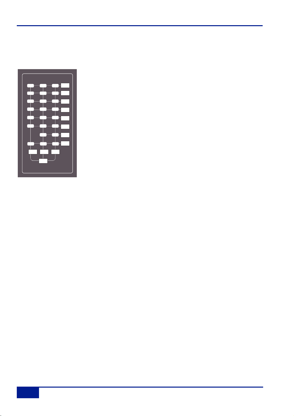
Central Routing Panel
In addition to the DAW transport controls and the console monitor pot, in
day-to-day operation you will probably find you use this panel more than any
other, so it’s worth taking a few minutes to fully understand its capabilities.
This panel provides access to channel routing, signal processing order, and
other facilities, on single or multiple channels. Channels can be selected in
a contiguous range or randomly across the console.
Channels are selected to the panel by pressing the select button at the foot
of each channel fader. The channel TFT meter will be outlined in green to
indicate the selected channel.
Normally the routing panel is ‘off’ – ie all displays are blank. Pressing any
channel select button, or the + and - buttons (on the panel) together, wakes
the panel up with a single channel selected – this will be either the select
button channel or the first channel of the previous selection.
Single channels can be selected at any time by pressing the channel select
buttons or using the +/- buttons. The currently selected channel will be
shown in the left hand (‘FROM’) window. The right hand display will be
blank.
To select a range of channels, press the TO button when a FROM channel
has been selected. Initially, the next consecutive channel will be displayed in
the right hand ‘TO’ window and indicated on the channel meter display. To
increment the range either use the +/- buttons, or press a second channel
select button to select the highest channel in the range; the highest channel
is shown in the ‘TO’ window.
Once a channel has been selected, The SELECT button allows non contiguous arrays of channels to be added
or removed from the current selection. The SELECT button will flash when active and any channel can added
or removed from the current selection via the select button on its fader. If SELECT is active the ALL button
can be used to select all the console channels.
To deactivate the routing panel, press the + and - buttons simultaneously, or re-press the channel select button
on the active channel, (if SELECT or TO are not active).
Once a channel or range of channels has been selected, selections and changes made on the routing panel
are made across all selected channels. If some functions are on and some are off on the selected channels,
the lowest numbered channel in the selection sets the initial state. For example, you select channels 3 to 6. If
channel 3 is assigned to a bus, then the first press on that bus routing button will deroute channels 3 to 6 from
that bus. If channel 3 is not assigned to a bus, then the first press on that bus routing button will route channels
3 to 6 to that bus.
Console Operator’s Guide
2-16
Duality Operator’s Manual
INPUT
FLIP
MIC
DYN POST
INSERT
INPUT
INPUT
123456
78
13 14 15 16 17 18
19 20 21 22 23 24
MIX A MIX B MIX C
+48V
INPUT MISC
LINE
CHANNEL IN
INS POST
EQ
IN
EQ
PROCESSING ORDER
EQ
IN
PROCESSING IN/OUT
PRE
FADE
CHANNEL OUTPUT
MON
RETURN
CHANNEL METERS
9101112
BUS
ROUTING
BUS
INS POST
DYN
POST
FADE
POST
FADE
SOLO
ISOLATE
SPLIT
FILTER
TO INPUT
EFX
CHAN
OUT
EFX
TO TRK
PAN
TO TRK
5.1
PAN
INC
ROUTE
PAN MODE
–
FROM
SET SELECT
TO
TO
SET
AUX
+
CLEAR
ALL
CHANNEL SELECT
UNDO
Page 29

Having selected a channel, or range of channels, all the functions in the area above can be
selected/deselected. Routing buttons 1-24 and MIX A, MIX B, MIX C, are self explanatory, as should most of
the buttons above. Note that changes made to the ‘PROCESSING ORDER’ are graphically indicated on the
channel TFT displays.
Items that may not be immediately obvious are as follows:
+48V – phantom power may only be selected here, as can INPUT FLIP and the channel input source –
‘CHANNEL IN’.
SOLO ISOLATE – Solo isolated channels will not be cut when other channels are soloed. Useful for FX
returns.
In the ‘PAN MODE’ section, INC ROUTE works in conjunction with the channel SELECT and TO functions, and
provides incremental bus routing for a range of channels. The selected channels will be incrementally routed
(or derouted if currently assigned) to consecutive busses starting from the first bus selected. 5.1 PAN enables
5.1 panning mode. PAN TO TRK routes the output of the selected channel’s pan to the Track busses. Stereo
panning is between odd/even pairs; 5.1 panning divides the track busses into four 6-channel groups. EFX TO
TRK replaces the channel feed to the Track busses with the active EFX send output. Stereo Cue EFX sends
are automatically routed to odd/ even pairs.
When SET AUX is selected, changes made to Cue Stereo and FX source and destination routing and On/Off
state, on any of the selected channels, will be copied to all selected channels, allowing the quick set up of aux
sends. Again, if some functions are on and some are off on the selected channels, the lowest numbered
channel in the selection sets the initial state.
SET and CLEAR provide an alternative way to set up routing. Press either SET or CLEAR, then select the
function(s) you wish to turn on or off. Pressing the select button on any channel will set or clear the selected
function(s).
Pressing ALL when SET or CLEAR are selected will make the SET or CLEAR button flash. A second press on
SET or CLEAR will make the assignment/de-assignment across all channels.
UNDO undoes all changes since the routing panel was last made active. As a safety measure, it requires two
presses to carry out the undo operation. On the first press, the UNDO button will flash, and a second press will
cancel all routing and channel settings that have changed since the routing panel was first selected. To cancel
and undo, deselect the routing panel by pressing the + and - buttons while the UNDO button is flashing.
Central Routing Panel
2-17
Duality Operator’s Manual
Page 30
Main Output Functions
As you are probably aware by now, Duality features a 6-wide main mix bus that can be configured either to
provide a full 5.1 surround mix or three stereo mix busses.
The six main mix busses are represented by three columns of indicators on this
panel which, in turn, represent three independent stereo pairs, MIX A, MIX B
and MIX C. Functions are assigned to these busses using the dedicated row
keys on the right of the matrix, in conjunction with the mix select keys at the
base of the matrix columns.
Each pair of busses has a switchable INSERT point with the option to be
placed pre (default) or POST the main output level control (normally the master
fader).
So, for example, lets assume all your channels are routed to MIX A, and you
want to insert an external stereo compressor on that bus. Press and hold the
button at the foot of the MIX A column and then press the button to the right of
the INSERT row; the associated INSERT indicator will light. Additional facilities
described below are assigned in a similar manner.
SUM mode allows the insert return to be summed with the main signal path. COMP assigns the master on-
board compressor to the selected bus(ses). This functions as single stereo unit inserted on a chosen stereo
bus or as a 5.1 compressor when in 5.1 mode (see below). The single master FADER is assigned to individual
stereo mix stems or as a 5.1 master fader in 5.1 mode. The fader can control the same level of all three stereo
busses simultaneously but can only set the level for one bus at a time. If not fader-controlled, the main output
level will be set at the last set level. Maximum gain is 0dB or +10dB if the +10dB function is selected. This
again can be set either on individual stereo busses or globally for 5.1 mixes.
The TO A function for MIX B and MIX C enable those busses to be folded down and added to MIX A. The
output of each stereo mix bus can be individually monitored (confidence-checked) by selecting the AFL
function.
All the above assumes you are working in ‘stereo’ mode. If you select the 5.1 MIX button at the foot of the
matrix, the MIX A, B and C assignment buttons function as a group. For example, if you select the
COMPressor, it will be automatically assigned to all six busses (as indicated by the matrix COMP indicators).
Selecting the 5.1 MIX button puts the matrix into 5.1 mode regardless of the state of the 5.1 PAN button on the
Central Routing Panel.
Console Operator’s Guide
2-18
Duality Operator’s Manual
MIX A MIX B MIX C
SUM SUM SUM
POST POST POST
INSERTINSERTINSERT
COMPCOMPCOMP
+10dB
+10dB
+10dB
FADER
FADER
FADER
TO ATO A
AFLAFLAFL
5.1 MIX
Page 31

Main Bus Compressor
Using the same classic design as found on the original SL4000 series
console, the main bus compressor can be used as a single stereo unit or as
a master 5.1 compressor. The compressor is assigned either to one of the
Mix A, B, C busses or the 5.1 mix bus via the main bus select matrix (see
previous page).
The ‘soft’ knee point of the compressor, ie. the level at which compression
start to take place, is set by the THRESHOLD control (± 20dB). This is
intentionally designed to change depending on the setting of the RATIO
control; decreasing the RATIO setting lowers the effective threshold, hence
maintaining the perceived ‘loudness’ of the compressed signal. The RATIO
switch has six settings, 1.5:1, 2:1, 3:1, 4:1, 5:1 and 10:1. ATTACK time is
switchable in six steps between 0.1 and 30 mS, and the RELEASE time is
selectable between 0.1 and 1.2 seconds in five steps. The AUTO release
selection adjusts the release time according to the signal envelope.
The gain MAKE-UP simply acts as a level control to compensate for the
lowered level that is a consequence of compressing the signal. This control
may be set so as not to change the overall output level when the
compressor is switched in. The meter indicates dBs of gain reduction.
In 5.1 mode, two buttons, SRND TO S/C and LFE TO S/C determine
whether the surround and LFE channels are included in the processing of
the side chain gain reduction, or not. A further button, S/C ∑,defeats the
normal 'loudest-bus-in-the-mix' side chain operation and substitutes a
summing mode so that the gain reduction is proportional to the soundfield
energy as opposed to the loudest individual signal.
Master Compressor
2-19
Duality Operator’s Manual
-20 +20
THRESHOLD
LFE
TO S/C
.31310
.1
ATTACK - mS
SRND
TO S/C
2
1.5
0
3
RATIO
COMPRESSOR
8
4
COMPRESSION
SL978
30
4
5
10
dB
12
16
20
0
MAKE-UP
.3 .6
.2
.1
RELEASE - S
IN
S/C
+
1.2
AUTO
Page 32

Master Fader
The master fader can be selected to control the stereo Mix A, B, C busses or the 5.1 mix
bus via the main bus select matrix (see previous page). The fader can control the level of
all three stereo busses simultaneously but can only set the level for one bus at a time.
The fader uses a 36-bit, Hi-Resolution MDAC.
The fader is provided with two scales. The one on the left is the normal scale; the one on
the right is for use with the +10dB function selected via the main bus select matrix (see
previous page).
The automation status button and LEDs fitted on this fader are used with the optional
automation system.
Following the injection of talkback and tone (see later), the main output busses feed
D-connectors on the centre section connector panel.
All the main mix busses are provided with LCD metering above the centre section. In
addition, the stereo Mix A bus can be metered on the centre section VU meters.
Console Operator’s Guide
2-20
Duality Operator’s Manual
MASTER
10 ·
15 ·
20 ·
30 ·
40 ·
50 ·
60 ·
∞ ·
0 ·
5 ·
·10
· 5
· 0
· 5
· 10
· 20
· 30
· 40
· 50
· ∞
Page 33

Track Bus Master Controls
The output level of the console’s 24 mono Track busses is set by a group of rotary
controls in the upper right of the centre section (see left). They all have 10dB of gain
when turned fully clockwise; an indent at the ‘12 o’clock’ position corresponds to 0dB
gain. Following level control, the bus outputs can be injected with tone (oscillator TRACK
button) and talkback (talkback SLATE button) before being fed to a D-connector on the
centre section connector panel.
An AFL function (post tone and talkback inject) is provided for each bus.The AFL signal
is intelligently assigned to left and right AFL busses. Selecting AFL on a single Track bus
output will route signal to both left and right AFL busses. Selecting AFL on odd and even
numbered Track bus outputs will route the odd numbered output to the left AFL bus and
the even numbered output to the right AFL bus.
A set of LCD bargraph meters in the centre section are dedicated to metering the bus
outputs.
Track Bus Masters
2-21
Duality Operator’s Manual
TRACK BUS
MASTERS
AF
+10
∞
BUS 1
AFL
∞
BUS 3
AFL
∞
BUS 5
AFL
∞
BUS 7
AFL
L
∞
+10
BUS
2
AFL
+10
∞
+10
BUS
4
AFL
+10
∞
+10
BUS
6
AFL
+10
+10
∞
BUS 8
Page 34

Monitoring
The large knob below the ‘MONITOR LEVEL’ display normally sets the level (up to 11!) of the main control room
monitors. The column of six buttons to the right enables this control to be used for the named alternative functions.
You will be monitoring on whichever set of speakers is selected from the ‘LS SELECT’ group: the Main 5.1
speakers (‘Main A’ – the default with no buttons selected), ALT 5.1 (‘Main B’), MINI A or MINI B.
The loudspeakers are fed from whatever source has been selected in the ‘MON SRC’ group of buttons. The
alternatives include the MIX A bus, the stereo downmix (STEREO MIX), and two external source selectors,
EXT A and EXT B. Sources will be intercancelling unless the SUM button is selected. All sources to the
monitoring are stereo except those brought in via the EXT A monitor source selector (see below).
The console has three monitor modes: 5.1, STEREO and MONO, selected via the ‘MON MODE’ group of buttons.
5.1 mode is the default (STEREO and MONO not selected) and delivers all six main busses to their respective
monitor outputs.
Selecting STEREO folds down the 5.1 inputs to the monitor path via a 5-2 gain-compensated matrix, and feeds the
result to left and right monitor outputs. MONO can be selected with or without STEREO and sums the left and right
monitor busses, feeding the result equally to the left and right monitor outputs.
Console Operator’s Guide
2-22
Duality Operator’s Manual
L
SL
LFE SR
MONITOR MUTE/SOLO
00.0
MONITOR LEVEL
DIM CUT
MONITOR
RC
EXTA EXTB
AFL/
OPTIONS
PFL
METERS
MISC
DVD SCD DAW EXT MIX SUM
DIM
AFL
PFL
SIF
H/P
MINI
MISC LEVELS
ALT
5.1
MINI
A
MINI
B
LS
SELECT
MON
FB A
FB B
CUT
PHONES
MON
SRC
SUM
EXTA
EXTB
STEREO
MIX
MIX A
MON
MODE
SOLO
SOLO
CLEAR
Ø
STEREO
MONO
Page 35

The Ø button precedes the MONO button and reverses the phase of the left monitor feed, providing a quick way
of checking for any phase anomalies in a stereo mix. If MONO is active, selecting the Ø button allows the
difference (L - R or the ‘S’ signal) to be monitored instead of the L + R sum.
The SOLO button turns the monitor cut buttons (see below) into monitor solo buttons. The SOLO CLEAR button
lights when any channel SOLO, S/Ch LSTN, AFL, or centre section AFL or MONITOR SOLO button is pressed.
Press SOLO CLEAR to cancel any Solo/AFL/PFL function.
If either MINI A or MINI B ‘LS SELECT’ buttons are selected, the left and right monitor busses are fed to the
corresponding stereo mini loudspeaker output. Mini level relative to the main monitors can be trimmed via the
main monitor pot by selecting MINI in the group of buttons to the right of the monitor pot. When a Mini speaker
output is selected, the 5-2 STEREO mix is automatically switched into the monitor circuit to deal with any 5.1
sources present.
The DIM button dims both main and mini loudspeaker outputs by a preset level. Set this level by selecting the
DIM button to the right of the monitor pot and turning the main monitor pot. The Dim circuit is automatically
activated when any of the following buttons are pressed: LISTEN, TB ALL, F/B A, F/B B, EXT T/B, Oscillator to
TRACK or MIX.
The CUT button cuts the monitor feeds to whichever set of monitors is selected. CUT is activated automatically by
the SLATE talkback function. CUT and DIM can also be activated externally via the GPIO/Talkback connector.
The six main monitor outputs can be muted individually with the L, C, R, SL, SR and LFE (sub) ‘MONITOR
MUTE/SOLO’ buttons. These become monitor solo buttons by selecting the SOLO button in the ‘MON MODE’
group (see above).
All the monitor outputs are available for connection to amplifiers via the centre section connector panel. The two
5.1 outputs (Main and Alt) feed two 25-way D-type connectors – ‘MON A’ and ‘MON B’; the two Mini outputs (Mini
A and Mini B) feed individual XLRs for left and right.
External Source Selectors
Two external monitor source selectors are provided. EXT A has four 5.1 inputs. These may be fed by any
source of six channels or less. The MIX selection provides an important fifth input to EXT A, which is used to
monitor the 5.1 Main Mix bus when mixing in 5.1 mode.
EXT B is a 2-channel selector that may receive up to four stereo sources. In either case, sources may be
summed together; this is particularly useful for generating complex foldback mixes or when stem mixing, as it
allows the recorded stems to be monitored together with the current mix.
To select an external monitor source, first press either the EXT A or EXT B button , choose a source from
those shown in the display, and then press the soft key under that source (or first press the key under SUM to
sum selected sources). Finally, route the external source(s) to the monitors by pressing EXT A or EXT B in the
‘MON SRC’ group of buttons. The LTR selection on EXT B provides monitoring for a surround encoder’s LtRt
output (see next page).
Inputs to the external source selectors are connected via D-connectors (four for External A, one for External B)
on the connector panel.
Monitoring
2-23
Duality Operator’s Manual
Page 36

Monitor Insert
The External A selector output (ie. all 5.1 sources) is automatically routed via a 5.1 insert point to which an
encoder/decoder system may be interfaced; this insert may be switched in/out of circuit using the Monitor
Options INS function (see next page). The insert send and return appear on two 25-way D-type connectors on
the centre section connector panel. The insert point also has connections for the two channel output from the
encoder, and the two channel input to the decoder. These allow monitoring of the encoder output (‘LtRt’)
signals and provide automatic routing of the External B selector outputs to the decoder inputs to enable
encoded recordings to be played back through the decoder. The logic for this is as follows:
• With no sources selected on External B, the encoder outputs are linked to the decoder inputs.
• Selecting any source on External B will route the External B outputs to the decoder inputs.
• Selecting EXT A and INS will monitor the insert return; if no source is selected on External B you will hear
the External A signals through the encoder and decoder. If a source is selected then you will hear the
decoded output of External B.
• Selecting EXT B and INS and selecting a source on External B will monitor External B.
• Selecting EXT B and INS with no source selected on External B will monitor the LtRt encoder outputs. The
LTR soft button lights to show this. Note that LTR is selected by turning off all other External B sources.
Monitor Metering
A dedicated set of six LCD bargraphs above the centre section provide a constant indication of ‘FOLLOW
MONITOR’ levels (ie. what you are currently listening to), plus a stereo meter for the SOLO/AFL bus and mono
PFL levels. See later for more on meter options. The ‘FOLLOW MONITOR’ meter feeds are available via a 25way D-type connector on the centre section connector panel, for use with external metering.
Console Operator’s Guide
2-24
Duality Operator’s Manual
Page 37

Monitor Options
A wide range of monitor options are available via the soft keys and associated display on the monitor panel.
Pressing the MONITOR OPTIONS button above the display produces the following choices; press the button
below an entry to select that option.
INS – Switches the encoder/decoder insert into the monitor path for use with 5.1 monitor sources selected via
the EXT B monitor selector.
PFM – Routes the PFL signal to the Mini A or B loudspeakers. In this mode, PFL level is controlled by the PFL
level control only – the Main and Mini monitor level controls have no effect.
SRA – Both sets of Main speaker outputs are capable of handling six channels. If you are mixing in 5.1 and the
client turns up with an alternative set of ‘front’ (LCR) speakers only, the surround feeds may be locked to the
Main 5.1 (Main A) outputs by selecting the SRA (‘Surround on A’) function. This allows you to switch to the
alternative LCR speakers, connected to the ALT 5.1 (Main B) output, and still maintain full surround monitoring.
A further option (A2B – see next page) enables the subwoofer output to be included in this arrangement.
LRA – Similar to the SRA function except that the LCR monitor feeds are locked to the Main A outputs but an
alternative set of surround speakers may be selected by switching to the Main B output. This can be useful in
rooms that work on both music, using full bandwidth separate surround speakers, and film using multiple lower
powered surround speakers.
Bass Management
BASS – Selecting this option produces a further layer of bass management options (see next page for options
held under CAL):
80H – Inserts a 7th order, 80Hz, low pass filter into the LFE monitor bus, to deal with listening to 5.1 material
that has a full range, unfiltered, LFE channel.
80H BMN LFO NEXT
EXTA EXTB
METERS
AFL/
PFL
MONITOR
OPTIONS
MISC
INS PFM SRA LRA CAL BASS
EXTA EXTB
METERS
AFL/
PFL
MONITOR
OPTIONS
MISC
Monitor Options
2-25
Duality Operator’s Manual
Page 38

BMN – Turns on the Bass Management system. This is designed to extend the low frequency response of the
monitoring system, and to simulate the 5.1 monitoring systems in TV and domestic environments. It inserts
12dB per octave, 80Hz high pass filters in the L, C, R, LS, RS monitor outputs, and feeds a pre high pass filter
mono sum of these five outputs to an 80Hz, 24dB per octave, low pass filter, which is summed with the LFE
monitor bus. Post this summing point, the combined signals feed via a 10Hz subsonic high pass filter before
reaching the subwoofer monitor output. These are the default filter slopes. Internal links (see Appendix for
details) allow the links to be set to 12dB or 24dB per octave, and to select whether or not the surround
channels are included.
Note that this option is stored separately for each set of speaker outputs (like the loudspeaker level calibration),
so it is possible to have Bass Management enabled on one set of speakers and not on others.
LF0 – Normally, the LFE bus level is increased by 10dB post the main monitor level control, as this is a
requirement for DVD playback. If you are mixing for SACD, or any other format that requires unity gain on the
LFE channel, select LF0 to restore the LFE bus level to unity gain.
NEXT – Produces a second layer of options:
A2B – Retains use of the main 5.1 subwoofer, even when you switch to the ALT 5.1 loudspeaker selection.
BMA – Uses the Alt 5.1 subwoofer instead of the main subwoofer for bass management when MINI A is
selected and BMN is on.
BMB – Uses the Alt 5.1 subwoofer instead of the main subwoofer for bass management when MINI B is
selected and BMN is on.
RTRN – Returns you to the top layer of the MONITOR OPTIONS selection.
A2B BMA BMB RTRN
EXTA EXTB
METERS
AFL/
PFL
MONITOR
OPTIONS
MISC
Console Operator’s Guide
2-26
Duality Operator’s Manual
Page 39

Monitor Level Calibration
The monitor calibration system enables the level of any loudspeaker connected to Duality to be trimmed by
±10db. Note that, with the monitor gain at maximum, a trim level of +10dB corresponds to unity gain through
the monitor section.
Do not attempt to carry out loudspeaker calibration
unless you have access to accurately calibrated test equipment
Selecting CAL in the first layer of MONITOR OPTIONS produces the following options:
Turn on the console oscillator (OSC ON) and select the PINK ON button; the default level for the console’s pink
noise output is +4dBu RMS. Adjust using the Pink trim pot in the oscillator section if necessary.
Set the monitor level control to the position you wish to correspond to the calibrated level. A level setting of 8.5
will provide 10dB of additional gain in hand.
Now select the required monitor system – Main 5.1, ALT 5.1, MINI A or MINI B.
Select the CAL menu. Pressing either AL or AR or AC will send pink noise to the Left or Right or Centre
loudspeakers respectively Adjust the level for the required SPL (eg. 85dBa C weighting, slow response, on a
suitably calibrated dB meter), by turning the main monitor pot left or right from its initial position.
Now work through the rest of the speakers (see below), checking before you calibrate the LFE output whether
the LFO option (see previous page) is off or on.
NEXT – selecting this in the first layer produces a second layer of calibration options:
Selecting ALS or ARS or ALF allows you to trim the Left Surround, Right Surround or LFE channels
respectively by ±10db, using the method described above.
ALS ARS ALF LFG BMN RTRN
EXTA EXTB
METERS
AFL/
PFL
MONITOR
OPTIONS
MISC
AL AR AC NEXT
EXTA EXTB
METERS
AFL/
PFL
MONITOR
OPTIONS
MISC
Monitor Calibration
2-27
Duality Operator’s Manual
Page 40

LFG – This stands for Low Frequency Gain and allows the gain of the contribution from the full bandwidth
channels to the subwoofer output to be adjusted. Like all the speaker calibration settings it must be set for each
set of speaker outputs (assuming Bass Management is in use).
Having lined up the six main speakers, select LFG. In LFG mode all speakers are initially muted, and the six
monitor cut buttons will light; uncut the left output, and with the bass management turned on (note that the
BMN selection in the BASS menu is duplicated in the CAL menu), adjust the LFG gain for a flat low end
response. Cut the left output, uncut the right output, and check this has a flat low end response. Repeat for all
channels. Depending on how well matched the monitors are, you may have to adjust the LFG gain slightly.
Note that when LFG is on, the LFE monitor output is always cut. This does not mute the actual subwoofer
output, only the LFE signals feeding it. This ensures that you are only measuring the contribution from the Bass
Management system.
SOLO / AFL / PFL
The console’s default solo mode is a destructive solo-in-place – soloing a channel cuts all other channels. The
alternative solo modes – AFL, PFL and Solo-in-front are selected via the soft key display on the monitor control
panel. Press the AFL/PFL button above the display to produce the following options:
AFL – Pressing a channel SOLO button routes the post channel pan signal, via the stereo AFL bus and the
AFL level control, to the currently selected monitor speakers.
PFL – Pressing a channel SOLO button routes a mono pre-fade signal, via the PFL bus and the PFL level
control, to the left and right Main monitor speakers. Optionally, PFL signals may be fed to the Mini
loudspeakers – see PFM in Monitor Options.
SIF – (Solo-In-Front) Pressing a channel SOLO button routes a mix of the AFL signal and the selected left and
right monitor sources to the monitor outputs. The SIF level control (select the SIF button to the right of the main
monitor pot and use the pot to set the level)) adjusts the balance between AFL signal and desk output.
ALT – Makes channel SOLO buttons intercancel with each other, so that soloing one channel will clear any
other solo selections.
MOM – This option makes all the channel SOLO buttons momentary.
Note that ALT and MOM do not affect the operation of centre section AFL and SOLO functions
Solo, AFL and PFL signals are all metered on the centre section SOLO meter. See Centre Section Metering
for more information.
AFL PFL SIF ALT MOM
EXTA EXTB
METERS
AFL/
PFL
MONITOR
OPTIONS
MISC
Console Operator’s Guide
2-28
Duality Operator’s Manual
Page 41

Cue/FX Send Master Controls
Each channel is fitted with two Cue Stereo and four mono FX sends for use as foldback,
feeds to effects devices, etc. The Cue Stereo outputs from each channel may be routed
to one of two busses – Stereo Cue A or Stereo Cue B. FX 1-4 feed their respective
busses.
The master output level controls for these busses (in the top right of the centre section –
see left) all have 10dB of gain when turned fully clockwise, and an indent at the ‘12
o’clock’ position, which corresponds to 0dB gain.
An AFL button is provided for each output. The AFL signal is intelligently assigned to left
and right AFL busses. Selecting AFL on a single FX output will route signal to both left
and right AFL busses. Selecting AFL on odd and even numbered FX outputs will route
the odd numbered output to the left AFL bus and the even numbered output to the right
AFL bus.
The two Cue Stereo and four mono FX outputs are available to external devices via a
D-connector on the centre section connector panel. The Cue outputs are also available
as sources to the Foldback outputs (see below).
A dedicated set of LCD bargraphs just above the master controls provides metering of
the Stereo Cue A, Stereo Cue B and FX busses (see Centre Section Metering).
Foldback and Headphone Outputs
The console provides three stereo outputs – Foldback A and B, intended for use in the
studio for headphones or LS playback, plus a stereo headphone feed for control room
use; a socket for this is provided beneath the buffer rail in the centre section. The
foldback outputs feed 6.35mm jacks on the centre section connector panel, from where
they may be connected to amplifier inputs.
The master controls for Foldback A and B are provided by two identical sections fitted
just below the main output compressor (see left – only Foldback B shown).
Each output has a dedicated LEVEL control, CUT, AFL, and six source selector buttons
with associated level controls:
The MIX 1 pot controls the contribution of Main stereo mix bus A (MIX A) and/or the
output of Cue Stereo A (CUE A), to the foldback mix.
The MIX 2 pot controls the contribution of the stereo downmix signal (ST MIX) and/or the
output of Cue Stereo B (CUE B), to the foldback mix.
In addition, the stereo Main monitor output (ST MON) and the output of External Source Selector B (EXT B)
may be selected as sources.
Dedicated F/B A and F/B B talkback buttons are used to add talkback to the foldback outputs.
HF and LF shelving equalisers are provided on the outputs.
N
∞
Cue/FX Send Masters
2-29
Duality Operator’s Manual
ST CUE A
∞
ST CUE B
∞
FX 1
AFL
AUX BUS
MASTERS
+10
+10
+10
AFL
AFL
AFL
∞
+10
FX 2
F/B B
LF
∞
∞
∞
∞
MIX 1
MIX 2
MIX 2
LEVEL
AFL
+10
FX 3
AFL
∞
+10
FX 4
HF
0
+
dB
ST MO
+0+
dB
EXT B
MIX A
CUE A
ST MIX
CUE B
CUT
+6
AFL
Page 42

A small area of the monitor control panel (see right) provides source selection (control room
monitor and foldbacks) and a CUT function for the console’s stereo headphone output. Note
that the F/B A and F/B B signals are taken from before the foldback master level and EQ
controls.
The level of the headphone output is set using the H/P button to the right of the Main
monitor pot, in conjunction with the pot itself.
Stereo Return Channels
The console’s four stereo return channels may be driven by the outputs of devices that have been fed from the
corresponding mono FX busses. Alternatively, the returns may be used for any additional stereo input required
for the mix. Inputs to the returns are interfaced to the console via a D-connector on the centre section
connector panel.
Four identical sets of controls are provided; the controls for Stereo Return 1 are shown
on the right. Each return can be routed to the console’s Main mix busses, with full control
of level and panning. Default routing is post the CUT L and CUT R input cut switches to
Mix A, B or C via the master LEVEL control.
To route a Stereo Return to the required mix bus, enable the Central Routing Panel by
pressing the + and - buttons simultaneously, then press and hold down the AFL/SEL
button at the bottom of the Stereo Return. The Routing Panel display will change to read
St 01, (02, 03) and the MIX A, MIX B and MIX C buttons above can be used to assign
the selected Stereo Return to the required bus(ses).
The BALANCE pot provides a differential Left/Right gain trim for the stereo input signal.
This is followed by a variable stereo WIDTH control, which can reduce the stereo image
to a mono centre phantom point source. The MONO button sums the inputs and
simultaneously alters the action of the BALANCE control to that of a conventional two
channel pan pot. This is very useful when you are using a mono FX device, as it saves
having to parallel the return inputs.
For 5.1 work, selecting the FB PAN button causes the WIDTH control to act as a
Front/Back pan pot. The FOCUS control progressively subtracts the front L R signals and
re-routes the sum to the C (Centre) bus (Bus 3).
Selecting the STEREO button defeats the surround panning options and provides switched routing via the
central routing panel. Press and hold the AFL/SEL button on the return to activate the panel, and use the
panel’s routing buttons to select MIX A, B or C (or combination thereof).
Return signal may also be fed independently, post the CUT L and CUT R input cut switches, to Foldback
outputs A and B by selecting the FB A and/or FB B buttons and adjusting the STUDIO control.
Console Operator’s Guide
2-30
Duality Operator’s Manual
MON
FB A
FB B
CUT
PHONES
STEREO RETURN 1
FB A
FB B
LRC
FOCUS
FULL
MONO
WIDTH
LR
BALANCE
+6
∞
LEVEL
∞
STUDIO
MIX A
MIX B
MIX C
ST EREO
FB PAN
MONO
CUT L
CUT R
AFL/SEL
Page 43

Misc Options
A couple of useful options can be accessed via the MISC menu. Press the MISC button above the display to
produce the following options:
0dB – Sets all faders to 0dB.
IND – When selected, pressing any fader’s fader button will set that fader to 0dB.
0dB IND
EXTA EXTB
METERS
AFL/
PFL
MONITOR
OPTIONS
MISC
Misc Options
2-31
Duality Operator’s Manual
Page 44

Communications
A group of communications buttons (talkback etc.) are fitted below the central routing
panel (see below). A built-in talkback microphone and pots to set the level of TB to
Foldback, Talkback Out (an external talkback feed), Slate level (talkback to Main
Mix, Track bus and channel outputs) and an incoming Listen mic, are provided in the
‘Comms” section above the DAW control TFT screen (see right).
Note that a gain control for the talkback mic preamp is provided on the connector
panel adjacent to the external talkback output jack. If required, an external talkback
mic may be connected to the console’s talkback distribution circuitry via an XLR on
the connector panel. When using this facility, turn the console mic preamp gain fully
anticlockwise (off) if you no longer wish the inboard mic to contribute to the talkback
system.
Note also that, apart from SLATE, which cuts the monitors, all the following functions dim the monitors. All the
buttons, apart from LISTEN and RED LIGHT, are momentary.
SLATE – Interrupts the Main Mix and Track bus outputs with talkback.
F/B A and F/B B – Adds talkback to the associated foldback outputs after
the level and cut controls.
EXT T/B – Sends talkback to an external feed, available via a 6.35mm jack
on the connector panel. Level is adjusted using the Talkback Out pot (see
above).
TB ALL feeds talkback to the foldback sends and the external talkback output.
LISTEN – Injects an external mic signal (connected via an XLR on the centre section connector panel) onto
whichever Mini loudspeaker set is currently active, and dims the main loudspeakers. This button is latching; the
level is adjusted using the Listen pot (see above). The mic is usually placed in the recording area. The circuitry
features SSL’s legendary listen mic compressor, the sound of which is much loved by many experienced SSL
users, so the connector panel provides a post compressor output jack – ‘Listen Mic Out’.
RED LIGHT – this provides an all-important isolated contact closure for hooking up to a studio red light via an
external relay box.
The talkback button functions are all duplicated on a Talkback/GPIO connector on the rear of the console,
as are the monitor CUT and DIM switches. See the Duality Installation Manual for more information.
Console Operator’s Guide
2-32
Duality Operator’s Manual
∞
Listen
∞
Slate
∞
Talkback Out
∞
TB to Foldback
RED
LIGHT
EXT
T/B
SLATE
TB
ALL
LISTEN
F/B A
COMMUNICATIONS
F/B B
Page 45

Oscillator
The word oscillator is a slight misnomer in this case, as the console actually
provides a comprehensive tone and pink noise generator!
The ‘Oscillator’ section (see right), located just above the DAW control TFT screen,
contains controls for frequency, level and routing of tone or pink noise to the Main
Mix and Track bus outputs and to the monitor outputs for use in monitor
calibration.
OSC ON – Activates the oscillator output (surprise, surprise!). It’s good practice to turn the oscillator off when
recording, to prevent any accidental routing to desk outputs.
PINK ON – Switches the output from tone to pink noise. Note that the pink noise level can only be adjusted
using the Pink ‘Cal’ preset.
The LEVEL control adjusts the level of the tone generator from -25dBu to +20dBu. When fully anticlockwise, a
preset ‘Cal’ level is selected that can be calibrated using the multiturn preset located below the level control; a
red LED lights to show when the level control is in the calibrated position. When OSC ON is selected, the
rotary FREQ switch provides six preset frequencies.
The oscillator may be routed to the Main MIX busses, the TRACK busses and the CHANNEL OUT(puts)
(individually or simultaneously).
The oscillator output is also available on an XLR on the centre section connector panel.
Oscillator
2-33
Duality Operator’s Manual
Cal
LEVEL
Tone
Pink
400 1K
100
48
FREQ
CHANNEL
OUT
TRACK
MIX
10K
PINK ON
15K
OSC ON
Page 46

Mix Reassign Matrix
This useful matrix, to the left of the main output compressor (see right), adds the
selected mix(es), post output level control, to the six Main Mix busses. Three stereo
mixes – stereo CUE A and CUE B, plus the output of the EXT B stereo monitor selector,
can be reassigned to Main Mix busses 1 and 2 (Mix A). The 24 Track busses are split
into four groups of 6, and are re-assigned in those groups to all of the Main Mix busses
(busses 1 and 2 to Mix A, 3 and 4 to Mix B, 5 and 6 to Mix C, etc.). This provides up to
four 5.1 stems or four triple stereo bus sets.
LFE Channel
This section (see right) enables a low pass filter to be switched (LFE FILTER) into the
LFE mix bus (Bus B Right) when working in surround. Two filter frequencies are provided
– the default 120Hz filter or, when the 80Hz button is pressed, a 80Hz option. The filter
slope is 12dB/Octave.
Stereo Mix Matrix
This matrix (see right) is used to sum the console’s Main Mix busses, with two exclusive
modes of operation.
Firstly, the three rotary controls and their associated ON buttons act as a 5.1 to Stereo
Downmix matrix to control the centre, surround and LFE contributions added to the
original 5.1 front L and R channels. By default, the downmix is sourced from the Main
Mix bus outputs, post processing and level control. INP PRE feeds the matrix directly
from the busses’ mix amps, thereby bypassing all processing.
The MIX A, B and C buttons are used to select a second mode of operation, which
provides a simple bus sum of the six Main Mix busses, when they are being used as
three stereo pairs or stems. The summing is post processing and level control. The
resultant stereo mix has a master LEVEL trim and a separate pre level control insert
point (INS). The insert return supports the ‘Sum’ option, as found on the Bus Select
Matrix for Main Mix bus insert points. This mode is selected in the SSL/Misc/Setup
menu, selected via the centre section TFT screen (see Setup Menu).
Console Operator’s Guide
2-34
Duality Operator’s Manual
MIX REASSIGN
CUE A
CUE B
EXT B
1-6
7-12
TRACKS
13-18
19-24
LFE CHANNEL
80HZ
LFE
FILTER
STEREO MIX
∞
LFE
MIX 2
∞
SURROUND
MIX 2
∞
CENTRE
TO
STEREO
MIX
∞
LEVEL
MAIN MIX
INP
PRE
ON
ON
ON
MIX
A
MIX
B
MIX
C
INS
+6
Page 47

Group Control Faders
The console centre section features eight control group master
faders. Each group master fader may control a number of slave
channel faders. Additionally, group master faders may control other
group master faders. Currently only VCA grouping is supported; servo
(moving fader) grouping will be added in a future software upgrade.
Group assignments may be stored as part of a Total Recall (option)
setup.
Selecting channel faders to a group is simple – press the select
buttons of the channels you want to include in the group then, in the
centre section, press the group button at the foot of the required
group fader (see right). The group display on each fader will reflect
your choice.
To assign a group master to be controlled by another group master,
press the group button on the group master to be controlled (ie. the
slave), and while keeping this button pressed, press the group button
on the group master that will control the slave. Use the same
procedure to deselect an assigned master from the slave group.
Pressing the SOLO or CUT button on a group master fader will have
the same effect as pressing the SOLO or CUT buttons on all the
slave faders. The underlying state these functions on slave faders can
be changed while a group master CUT/SOLO is active, but the group
master CUT/SOLO state can not be overidden by the local function.
Group fader CUT (but not SOLO) buttons may be automated if the optional automation system is active. See
Section 5 for more details.
VCA mode grouping emulates a traditional non-moving fader grouping system – moving the group master
changes the gain of the slaves but doesn’t physically change the position of the slave faders. The gain equals
the gain of the slave plus the gain of the master (in dB). Assigning a fader to a group immediately changes the
gain by the amount the master is displaced from 0dB.
Group Control Faders
2-35
Duality Operator’s Manual
24
fader
rec
play
match
switch
1
2
3
4
5
6
7
8
group
select
·10
· 5
· 0
· 5
· 10
· 20
· 30
· 40
· 50
· ∞
GROUP 1
GROUP 1
fader
rec
play
match
switch
1
2
3
4
5
6
7
8
group
·10
· 5
· 0
· 5
· 10
· 20
· 30
· 40
· 50
· ∞
Page 48

Centre Section Metering
The panel above the main centre section features LCD and analogue metering for the console’s main and
auxiliary outputs:
On the left of the centre section meter bridge are six sets of LCD bargraphs. These are dedicated to the
metering of (from left to right) the following busses:
• AL, AR, BL, BR, CL, CR MAIN MIX flipping to L, R, C, LF, LS, RS depending on whether the master
fader is in 5.1 mode or assigned individually to the A B C stereo mix busses.
• L, R ST MIX (downmix)
• L, R, C, LF, LS, RS FOLLOW MONitor
• L, R SOLO, AFL, PFL bus
• L, R CUE A and CUE B
•1-4FX SENDs
• 1-24 Track BUSSES
The standard scale is +24dB for 0dBFS (top of the scale). Options for different 0dBFS levels are available via
the SSL/Misc/Setup menu (see next page).
To the right of the bargraphs are two VU meters and a phasemeter. These meter the Left and Right outputs of
three mix busses, as selected via the METERS menu (see below).
Console Operator’s Guide
2-36
Duality Operator’s Manual
CLIP
0
2
4
6
8
10
14
20
30
40
50
60
L C R LS RS LF L R
CLIP
0
2
4
6
8
10
14
20
30
40
1 2 3 4 5 6 7 8 9 10 11 12 13 14 15 16 17 18 19 20 21 22 23 24
CLIP
CLIP
0
2
4
6
8
10
14
20
30
40
50
60
5.1 MIX ST MIX
CLIP
0
2
4
6
8
10
14
20
30
40
CLIP
0
0
2
2
4
4
6
6
8
8
10
10
14
14
20
20
30
30
40
40
50
50
60
60
L C R LS RS LF L R
FOLLOW MON SOLO
CLIP
BUSSES 1-24
CLIP
CLIP
0
0
2
2
4
4
6
6
8
8
10
10
14
14
20
20
30
30
40
40
50
50
60
60
0
2
4
6
8
10
14
20
30
40
CLIP
0
2
4
6
8
10
14
20
30
40
CLIP
CLIP
0
0
2
2
4
4
6
6
8
8
10
10
14
14
20
20
30
30
40
40
50
50
60
60
L R
CUE A
CLIP
0
2
4
6
8
10
14
20
30
40
CLIP
CLIP
0
0
2
2
4
4
6
6
8
8
10
10
14
14
20
20
30
30
40
40
50
50
60
1 2 3 4
FX SEND
60
L R
CUE B
Solid
State
Logic
MON
LEFT RIGHT
ST MIX
PHASE
MIX A
SOLO
Page 49

Meter Options
Meter options are provided by soft key selections on the monitor panel; select the METERS button to produce
the following selections for the VU meters :
MON – Feeds the current Left and Right monitor outputs to the meters.
DMIX – Feeds the stereo downmix output level to the meters.
MIX A – Feeds the Main Mix A bus to the meters.
Note that any AFL or SOLO selection will automatically cause the VU meters to meter the console’s solo bus.
The METERS menu also holds additional modes for the TFT channel and centre section bargraphs:
PK – Switches the meters to peak reading mode; peak readings are held for 3 seconds.
HLD – Select this to hold the peak readings indefinitely.
CLR – Press to clear the currently held peak readings.
Setup Menu
The centre section TFT screen provides access to a setup menu that holds a number of useful console-related
items. Select SSL followed by Misc and then Setup (see Section 3 if you are not familiar with the use of the
TFT and its associated soft keys).
To change a setting, use the left hand D-Pot to select the item, then press the D-Pot to enter adjustment mode.
Turn the D-Pot to the desired setting and press it a second time to save the setting to non-volatile memory.
Input Cut Enable – If set ON, the channel strip CUT button will cut prefade sends, ie. Aux and CHOP sends.
Stereo Mix Insert Mode – This enables the stereo mix matrix ‘SUM’ option to be selected, where the insert
return sums with the main signal path. Select REPLACE to disable this function.
Analogue Meter Scaling – Select from four options for 0dbfs =: 18, 20, 22, 24dbu.
TFT Backlight Brightness – Use this to adjust the backlight level to your preferred value between 4 and 32.
Scribble Strip Brightness – As above but for the channel scribble strip (range 4-32).
Meter Options
2-37
Duality Operator’s Manual
Page 50

The next four items in the Setup menu are concerned with DAW interconnection, but are included here for
completeness; see Section 3 for more details. Note that changes to any of these DAW settings will require a
console reboot before they take effect.
First Physical DAW Channel – Select the console channel number that is controlling the first DAW track
number.
DAW Channel Count – Select the total number of channels dedicated to DAW control (8-48 in steps of 8).
DAW Centre Section – Select the MIDI port that connects the console’s centre section master controls to the
DAW; normally MIDI 1.
DAW Interface – Select from HUI, Logic Audio, Nuendo, Digital Performer, Sonar.
Console Channel Count – Should be set to the size of your console 48, 72 or 96. This setting determines the
range of channels selected by the Central Routing Panel’s ALL button.
Turn Off Display After – Shuts off the TFT display after a predetermined time: 30 mins to 5 hours in 30 minute
increments.
DAW Control
Most of the left hand side of the centre section is taken up with a TFT screen and control panel dedicated to
use with your workstation. See Section 3 of this manual for full details.
Console Operator’s Guide
2-38
Duality Operator’s Manual
Page 51

Duality Operator’s Manual
3-1
Introduction
When connected to a Digital Audio Workstation that supports the HUI or Mackie Control Universal (MCU) control
protocols, the Duality console becomes a powerful digital work surface controller, giving direct access to the
most important controls within the DAW. The console faders can be used to control the workstation faders and
sends, the channel D-pots can be used to control pans, sends and I/O functions, and the Master Control Panel
and plug-in controller provide easy access to a range of other parameters.
For an up to date list of compatible DAW applications please visit: http://www.solid-state-logic.com. This section
of the manual is largely based on use with Digidesign’s Pro Tools package, with supplementary pages for other
packages, whose functionality will depend on their implementation of the HUI or MCU control protocols.
DAW Controller Features Summary
• Direct access to all major DAW mixing, editing and automation parameters
• Direct control of plug-in settings
• Integral colour TFT display with dedicated control buttons
• High resolution rotary encoder (D-pot) on every channel provides control of DAW pans, sends and I/O
routing, and for MCU compatible applications, Plug-ins and Instruments
• High quality motorised faders to write/replay level moves in your DAW
• Simple switching between console layer and DAW control layer
• Full remote control implementation
• Operation independent of platform or application
Communication with the DAW
The Duality console connects to a DAW via sixteen (eight in, eight out) MIDI ports on the rear panel of the
console. Duality emulates multiple HUI or MCU controllers depending on the control surface support required by
the connected DAW. Note that normally Duality’s MIDI port 1 connects the first set of eight channel assigned to
DAW control and the centre section Master controls; MIDI ports 2 to 6 connect further console channels in
blocks of eight up to a maximum of 6. This can be changed in the SSL/Misc/Setup menu (see below), as can
the number of Duality channels dedicated to DAW control (from 8 to 48) and the position of the first of these
channels. MIDI port 8 IN is used exclusively for MTC and MMC messages required by the console automation
system; port 7 is currently unused.
Setup Menu
Four items in the SSL/Misc/Setup menu, accessible via the centre section TFT, are concerned with DAW
interconnection. Note that changes to any of these settings will require a console reboot before they take effect.
To change a setting, use the left hand D-Pot to select the item, then press the D-Pot to enter adjustment mode.
Turn the D-Pot to the desired setting and press it a second time to save the setting to non-volatile memory.
First Physical DAW Channel – Select the console channel number that is controlling the first DAW track
number.
Section 3 – DAW Control Guide
Page 52

DAW Channel Count – Select the total number of channels dedicated to DAW control (8-48 in steps of 8). If
you change this figure you will need to change the number of controllers assigned in the DAW.
DAW Centre Section – Select the MIDI port that connects the console’s centre section master controls to the
DAW; normally MIDI 1. If you are using one of the MCU Logic protocols, and you change this item, you will need
to change the control surface layout in the DAW application.
DAW Interface – Select from HUI, Logic Audio, Nuendo, Digital Performer, Sonar.
For further details on DAW hardware installation, please read the Duality Installation Manual.
Refer to your DAW manual for information on how to configure its software. Once configured and connected,
communication with the DAW will be initialised, and the level of Duality’s channel faders, rotary controls and
master functions will be set to match the DAW controls (provided you are ‘DAW Focus’ mode).
If the Duality console is not found, your DAW will inform you that a controller is not present. If MIDI
communications fails on any bay, recheck the DAW configuration, MIDI connections and MIDI interface for
correct operation.
When using your DAW without the Duality console, you should remove Duality from the MIDI controllers section
of your DAW (please see information specific to your DAW for this).
Overview
Duality’s faders, and its Solos and Cuts panels, can be switched between controlling the analogue audio signal
path and the DAW by pressing the Console Focus button – see below. The Motion Controls, Master Control
Panel and Plug-in Editor always control the DAW. The illustration above indicates those console elements that
relate directly to a DAW in ‘DAW Focus Mode’.
Duality Operator’s Manual
DAW Control GuidE
3-2
Channel Meters Master Control PanelPlug-in Editor
Channel Faders Solo and Cuts Panels Motion Controls
Page 53

Master Control Panel
Duality Operator’s Manual
3-3
D-pots
Each channel has a continuous rotary control or ‘D-pot’ The Plug-in Editor (HUI Mode only) has four D-pots for
control of plug-in parameters.
Console Focus
The console can be selected to one of two important modes using the Console Focus button (8), located on the
Master Control Panel. This switches the channel meters, faders, solo and cut buttons between control of the
analogue signal path and the DAW. When the Console Focus button is illuminated, Duality is in ‘Analogue Focus
Mode’. When the Console Focus button is not illuminated, Duality is in ‘DAW Focus Mode’. This section
describes operation of the console in DAW Focus Mode.
Analogue Focus Mode
The channel faders control the channel audio output level for that fader. The channel meters indicate analogue
input/output levels for that channel. The channel D-pots are available to control DAW parameters.
DAW Focus Mode
The channel faders control DAW fader levels. The meters indicate DAW track levels. The channel D-pots are
available to control other DAW functions such as pan or send level.
Digital ‘In-line’ Mode
When the console is in DAW Focus Mode, analogue level control can be assigned to the D-pots by pressing the
CHANNEL button (1) on the Master Control Panel.
The Master Control Panel (HUI Mode)
The Master Control Panel contains a mixture of master functions and modifier buttons for DAW control:
Channel Banking Controls (6)
Duality can have up to 96 touch sensitive moving faders. However, you can only have a maximum of 48 faders
assigned to DAW control in HUI mode, and Pro Tools only supports 4 HUI controllers, giving a maximum of 32
faders. If the DAW session has more tracks than this, Duality can ‘bank flip’ its faders to control any number of
virtual faders within the DAW.
3 4
7
MUTE
PRE/POST
BYPASS
DEFAULT
8
UNDO
9
ESC
SHIFT
10
CTRL
SUSPEND
AUTO
11 12
SAVE
ENTER
OPTION
ALT
RDY
ALL
ALT
STATUS
TRANS
13
MEM
MIX
EDIT
SEND
CHANNEL
1
PAN
RDY SEL
AUX2
2
Push to Flip
5
CHANNEL
6
EDIT
INPUT
OUTPUT
ASSIGN
Page 54

DAW Control GuidE
3-4
Duality Operator’s Manual
To flip the console’s faders to the next set of DAW faders, press the right bank button. To flip back to the
previous set, press the left bank button. Any number of virtual faders can be controlled from Duality using the
banking buttons.
To scroll the faders one at a time, press the CHANNEL button (located between the two banking arrow buttons)
followed by the left or right banking buttons; the CHANNEL button will light to indicate it is in ‘Channel’ mode.
Press the CHANNEL button once more to switch back to ‘Bank’ mode.
DAW Window Buttons (13)
This group of buttons provides instant access to the various windows within the DAW. Press them once to
display or hide the relevant menu:
ALT Opens or closes the floating window for the currently selected plug-in
STATUS Opens or closes the Session Setup window
TRANS Opens or closes the Transport window
MEM Opens or closes the Memory Locations window
MIX and EDIT Brings that window to the foreground. The button lights to show the currently active window
DAW Utility Buttons (9)
This group of four buttons provide shortcuts to useful functions on the DAW.
SAVE will light when unsaved data is present. Pressing it once will cause the SAVE button to flash. A second
press will save the Pro Tools session. Press ESC to cancel a pending save.
The UNDO button will light if undo is available, and flash if redo is available. Press the UNDO button to undo the
last function and press ALT + SHIFT + UNDO to redo the last function.
ENTER duplicates the function of the ENTER key on the computer keyboard.
ESC(ape) duplicates the function of the ESC key on the computer keyboard.
3 4
MUTE
PRE/POST
UNDO
ESC
SAVE
9
ENTER
ALT
STATUS
1
SEND
CHANNEL
AUX2
2
INPUT
OUTPUT
PAN
RDY SEL
Push to Flip
5
6
EDIT
CHANNEL
ASSIGN
7
BYPASS
DEFAULT
8
SHIFT
10
CTRL
SUSPEND
AUTO
11 12
OPTION
ALT
RDY
ALL
TRANS
13
MEM
MIX
EDIT
Page 55

Master Control Panel
Duality Operator’s Manual
3-5
Modifier Buttons (10)
These buttons modify the function of other buttons, and their practical use is detailed under the relevant topics in
this section. For your information:
OPTION typically changes the function of a single button to affect all similar buttons. Thus holding down
OPTION and pressing a channel CUT button will cut all DAW channels. It is the direct equivalent of the Mac™
Command (Apple) key.
SHIFT allows selection of multiple objects or controls. It is a direct equivalent of the computer keyboard shift key.
ALT increases the resolution of rotary controls and inverts switch selections when held down. It is a direct
equivalent of the Mac keyboard Option key.
CTRL disengages grouping when held down. It is a direct equivalent of the Mac keyboard Ctrl key.
The Default Button (7)
Faders, pans and sends can be reset to their default values using the DEFAULT button:
Resetting Pans
Select the PA N button on the Master Control Panel, and all Duality’s D-pots become pan controls. Hold
the DEFAULT button while pressing the D-pot on the channel you wish to reset. Hold down OPTION and
press DEFAULT to perform a reset across all pans.
Resetting Faders
Hold the DEFAULT button while pressing the SEL (Select) button on the channel you wish to reset. Hold
down OPTION and press DEFAULT to perform a reset across all faders.
Resetting Sends
Select the SEND button on the Master Control Panel. Turn the Master D-pot to scroll through the list of
available sends. Hold the DEFAULT button while pressing the channel D-pot on the channel you want to
reset. Hold down OPTION and press DEFAULT to perform a reset across all sends.
Resetting Plug-ins
Hold the DEFAULT button and press the Plug-In Editor COMPARE function. The plug-in default value is
either the factory setting or user setting determined within the DAW.
Page 56

DAW Control GuidE
3-6
Duality Operator’s Manual
Channel Functions
In DAW focus mode, the channel meters, faders and part or all of the Solo and Cuts panels control the DAW
and display its status.
DAW Meters
In DAW focus mode, Duality’s channel meters flip to a stereo mode to indicate the level of
the DAW signal path. Mono tracks are displayed on the left meter only. When a signal
reaches 0dBFs, the corresponding OVL tally will light to indicate that the DAW signal level
has clipped.
The meters duplicate the function of meters within the DAW, and show the same
information. They also follow DAW pre or post fader meter settings, as set within the
DAW.
OVL tallies can be reset using the F1 function in the Fkys soft key menu
Status Indicators
The meter shows the status of the corresponding DAW track.
REC flashes when the track is in record ready and lights when the track is in record.
EDIT indicates that the track is selected for editing with the plug-in controller.
Multi-channel Metering (TDM Systems Only)
Multi-channel metering can be displayed by pressing OPTION + SOLO on a selected multi-channel track. The
next two stereo meters are used to show the additional information. Normal metering functionality resumes after
deselecting the SOLO function.
Channel Fader
The channel fader can control any virtual DAW fader including Channel, Master, Auxiliary,
MIDI tracks or Instrument tracks. The calibration of the fader will depend upon the DAW
(please refer to your DAW manual for more details). Pressing ALT will display the gain of
the DAW fader on the fader scribble strip when you move the fader.
Fader Grouping
Channel faders will follow any grouping enabled within the DAW. Faders can be
disengaged from a fader group simply by holding down the CTRL button or by touching
one fader in a group while adjusting another fader’s level. Relative fader levels are
maintained upon release of the fader.
fader
rec
play
match
switch
1
2
3
4
5
6
7
8
group
·10
· 5
· 0
· 5
· 10
· 20
· 30
· 40
· 50
· ∞
select
Page 57

Channel Functions
Channel Solo and Cut Panels
Channel D-pot
Each channel has a continuous rotary control or D-pot. This can be used to control send
levels and panning, and to assign input, output and send routing. See the following pages
for more details.
The D-pot includes a push switch that is used (depending on the centre section mode) to
select sends to be pre or post fade, to mute sends and to confirm I/O selections. Again,
see the following pages for more details.
Solo and Cut Buttons
Two sets of SOLO and CUT buttons are provided on each channel. The upper set is
associated with the signal path controlled by the channel D-pot, and the lower set with the
signal path under fader control. Thus in Analogue Focus mode, and with CHANNEL mode
selected, the lower set of buttons control the analogue path and the upper set control the
DAW channels. Changing to DAW Focus reverses this.
One easy way to tell if you are soloing a Duality or DAW channel is that channels cut by a Duality solo have a solid
lit CUT button, and channels cut by a DAW solo have flashing CUT buttons (hence the term ‘Rude Solo’? – Ed.).
Holding down OPTION and pressing a channel SOLO/CUT button will select/deselect that function across all
channels. If channels are already solo’d, then this action will turn off all solo buttons, providing a quick way to
clear solos.
Solo Isolate
Holding down ALT and pressing a channel SOLO will put a channel into ‘Solo Isolate’ mode. This prevents that
channel from being cut when a SOLO is activated on another channel. This is particularly useful for FX return
tracks.
Channel Select Button
The channel SEL button can function as a channel select button, a track record enable or a plug-in edit enable
button, depending on the mode selected on the Master Control Panel. See over the page for more details.
Scribble Strip Displays
When a Duality channel fader is controlling a DAW fader level, the channel scribble strip will indicate a four
character version of the DAW channel name. When controlling the analogue channel it displays the number of
the fader, eg ‘Fad 24’.
The scribble strip can also display other information such as: automation status, grouping information, monitor
information, input/output routing, send routing, send pre/post information, fader level display, and pan position
(see the following pages for details). An indication of the selected function is provided in these other modes –
Pan, ASGN etc.
Duality Operator’s Manual
3-7
CUT
SOLO
Fad 24
Ohd L
SEL
SOLO
CUT
Page 58

DAW Control GuidE
3-8
Duality Operator’s Manual
Channel SEL Button – Record Ready/Edit/Select
The function of the channel SEL button depends on the mode selected by the centre section RDY, EDIT and
SEL buttons (5) on the Master Control Panel.
Record Ready Mode
When RDY is selected, all the channel SEL buttons become Record Ready buttons. Pressing a channel SEL
button puts that DAW track into Record Ready (provided that the DAW track has an input routed). The REC tally
in the channel meter display flashes to show that the track is in ready.
Ready All
Track arming can be set or cleared across all channels by using the master RDY ALL button (12). This button
flashes if any DAW tracks are in Record Ready. Pressing this button while it is flashing will clear all track arming.
Record Safe
To put a DAW track into Record Safe (so it cannot be selected to Record Ready) hold down ALT and press the
channel SEL button. Hold down ALT + OPTION then press any SEL button to select all tracks to Record Safe.
Edit Mode
With the EDIT button selected, a channel SEL button can have a number of different functions:
As long as the Master Control Panel BYPASS button is not selected, pressing a channel SEL button assigns the
Plug-in Editor to that channel. The EDIT flag on that channel’s meter display will light to confirm that this is the
EDIT channel (see Plug-in Editor for more details). A double press on the SEL button will select the first plug-in
on that channel for editing. Successive double presses will select the next plug-in on that channel.
Selecting the BYPASS button (4) on the Master Control Panel changes the channel SEL buttons to BYPASS
buttons. Pressing a channel SEL button will bypass all plug-ins on that channel. The channel meter display’s
EDIT flag will light to show that all plug-ins are bypassed.
1
SEND
CHANNEL
AUX2
2
3 4
INPUT
OUTPUT
MUTE
PRE/POST
UNDO
ESC
SAVE
9
ENTER
ALT
STATUS
PAN
RDY SEL
Push to Flip
5
CHANNEL
6
EDIT
ASSIGN
7
BYPASS
DEFAULT
8
SHIFT
10
CTRL
SUSPEND
AUTO
11 12
OPTION
ALT
RDY
ALL
TRANS
13
MEM
MIX
EDIT
Page 59

Channel Functions
Duality Operator’s Manual
3-9
Select Mode
With the SEL button (5) on the Master Control Panel selected, all the console’s channel SEL buttons become
track select buttons. They perform the same function as clicking on a channel in the DAW screen display.
A double click on a SEL button will open the channel naming pop-up for that channel. Multiple channels can be
selected by holding down the SHIFT button while selecting further SEL buttons or by holding down the first SEL
button you pressed while you select more channels. Note that this latter method only works within blocks of
channels corresponding to a single HUI interface.
Hold down OPTION and press any SEL button to select all channels. Hold down ALT and press any SEL button
to invert the state of all select buttons.
Working with the Channel D-pots
The channel D-pots can control the DAW’s channel pan, send (aux) levels and pan, routing assignment and
analogue audio levels. Each D-pot also has a switch which is activated by pushing down on the D-pot.
The channel D-pot function is selected on the Master Control Panel by the Master Send D-pot (2) and six
associated buttons (1) and (3). The scribble strip above the channel D-pots shows which function is currently
selected. A further two buttons (PRE/POST and MUTE) change the function of the D-pot push switches.
Pan Mode
Select the PA N button on the Master Control Panel, and the channel D-pots become pan controls for the DAW.
The D-pot scribble strip displays Pan.
Pressing the PA N button a second time (it flashes in this mode) allows you to access a second pan control for
stereo channels, according to the DAW configuration. The D-pot scribble strip displays Pan R in this mode.
Press the PA N button again to return to normal pan mode. Holding down ALT displays a pan’s numeric value on
the channel scribble strip as you adjust the control.
Channel Mode
Select the CHANNEL button on the Master Control Panel, and the channel D-pots control the analogue gain of
the channel strip. The D-pot scribble strip will display the analogue fader number (eg Fad 12).
Switching to Analogue Focus mode will swap the analogue gain and the DAW gain between D-pot and channel
fader. Individual channels can be swapped by pressing the channel D-pot.
Send Mode
Select the SEND button on the Master Control Panel, and the D-pots become level controls for any sends or aux
send levels within the DAW.
The Master D-pot (2) selects which of the available sends (A-E or 1-5) is being controlled by the channel D-pots.
The selected send is shown in the display window above the Master D-pot (and on the channel D-pot scribble
strip). The channel scribble strips show the name of the currently selected send. Turning a channel D-pot will
alter the level of the selected send from that channel. Holding down the ALT button allows you to make fine
adjustments to the gain. See over the page on how to use faders to set send levels.
Page 60

DAW Control GuidE
3-10
Duality Operator’s Manual
Setting Sends Pre/Post Fader
When working with sends it is useful to be able to flip a send between pre and post fader. If necessary, first
select the PRE/POST button (4) on the Master Control Panel. Pushing a channel D-pot will now switch the
selected send on that channel between pre and post. The green LED below the D-pot lights to show PRE is
selected.
To change mode on all channels, press and hold the Master Control Panel OPTION button then press any
channel D-pot. All channels will switch to pre or post.
Muting a Send Output
To mute a send output, select the MUTE button (4) on the Master Control Panel and push the channel D-pot.
The green LED below the channel D-pot will light to show the channel is muted. To mute or un-mute all
channels, press and hold the OPTION button then press any channel D-pot.
Flipping Send Levels to the Faders
To flip send levels from the D-pots to the channel faders, press the Master D-pot (2) – hence Push to Flip! The
channel faders now control send levels and the fader CUT button will mute a send. The channel D-pot controls
panning on stereo sends.
In this ‘flipped’ mode, PRE/POST mode is automatically selected for the D-pot switches, so pushing a D-pot will
toggle the send pre/post on that channel. The green LED below the D-pot lights to show PRE is selected.
Note that the fader SOLO button will still solo the channel, not the send.
1
SEND
CHANNEL
AUX2
2
3 4
INPUT
OUTPUT
MUTE
PRE/POST
UNDO
ESC
SAVE
9
ENTER
ALT
STATUS
PAN
RDY SEL
Push to Flip
5
CHANNEL
6
EDIT
ASSIGN
7
BYPASS
DEFAULT
8
SHIFT
10
CTRL
SUSPEND
AUTO
11 12
OPTION
ALT
RDY
ALL
TRANS
13
MEM
MIX
EDIT
Page 61

Input, Output and Send Routing
Duality Operator’s Manual
3-11
Input, Output and Send Routing
The channel D-pots can also be used to assign signals to inputs, outputs and the aux sends of a DAW:
Viewing Input, Output and Send Routing
The input, output or send routing for all DAW channels can be displayed on the channel scribble strip by holding
down the INPUT, OUTPUT or SEND button (3) on the Master Control Panel and using the Master D-pot to
select which of the available sends you wish to display.
Setting input, Output and Send Routing
To make or change an input, output or send assignment:
1. Select ASSIGN + INPUT or OUTPUT or SEND (3) on the Master Control Panel.
When using SEND, use the Master D-pot to select the send you wish to change
2. The D-pot scribble strip will now read ASGN and the fader scribble strip will indicate the current routing for
the DAW channel.
3. Turn a channel D-pot to scroll through a list of available DAW inputs or outputs (names are derived from the
DAW I/O settings, not Duality). The list will appear in the channel scribble strip. The green LED below the Dpot will flash.
4. Push the D-pot knob to select the current assignment; the green LED will become solid and a ‘>’ symbol will
appear in front of the assigned signal (for example, ‘>Out3-4’).
5. Press the ASSIGN button once more to exit assign mode. This will also commit any changes you have made,
that have not been confirmed by pressing the D-pot.
6. Pressing ESC at any time will abort the assignment process.
Assigning Signals to Multiple Channels
Holding down OPTION then pressing any channel D-pot will assign that channel’s input to all channels. Holding
down SHIFT + OPTION will assign that channel’s input to all selected channels. Select SEL mode on the Master
Control Panel then press the SEL buttons on the channels you wish to route to.
Holding down OPTION + ALT then pressing a channel D-pot will incrementally route that channel’s input to all
channels. For example, selecting input 1 as the input to channel 9, then holding down OPTION and ALT, before
pressing the channel 9 D-pot, will route input 1 to channel 9, input 2 to channel 10, input 3 to channel 11 and so
on across the entire DAW.
Holding down SHIFT + OPTION + ALT will incrementally route that channel’s input to all selected channels.
Select SEL mode on the Master Control Panel then press the SEL buttons on the channels to which you wish to
route.
Assigning a Channel to Multiple Outputs
Hold the CTRL button and select another output. The currently assigned output will have a ‘>’ symbol in front of
it (for example, ‘>Out3-4’), and other added outputs will have a ‘+’ (for example ‘+Out5-6’) until you assign it.
In the scribble strip, an ‘@’ symbol indicates that an item is inactive (ie. routed but muted). The ‘$’ symbol
indicates that more than one output is assigned, and at least one of those is inactive.
Page 62

DAW Control GuidE
3-12
Duality Operator’s Manual
Motion Control
Basic Transport Controls (14)
Dedicated transport controls are provided for direct control of the DAW:
REWIND Press ‘n’ hold to rewind the DAW (increment depends upon DAW Display mode)
FAST FORWARD Press ‘n’ hold to fast forward the DAW (increment depends upon DAW Display mode)
STOP Stops playback or recording
PLAY Commences playback from the current cursor position or the last locate point, depending on
DAW settings
RECORD Engages DAW recording for currently armed tracks
Additional Transport Controls (15)
PRE Toggles the DAW pre-roll function. See next page for setting pre-roll time
POST Toggles the DAW post-roll function. See next page for setting post-roll time
IN Captures the current DAW position as the Start edit time
OUT Captures the current DAW position as the End edit time
RTZ (Return-To-Zero) Returns the playback cursor to the Session start time
END (Go-To-End) Moves the playback cursor to the Session end time
LOOP Toggles Loop mode on/off (hold down CTRL for Loop Record mode)
Q PUNCH Toggles the DAW Quickpunch recording status on/off
ONLINE Puts the DAW on line for synchronisation
See next page for details of the AUD button.
AUD IN OUTPRE POST
15
RTZ END
MOTORS
TRIM
JOIN
OFF
REVISE
LOOP
TRIM
LOK
END
PUNCH
DISCARD
AUTOMATION
14
TRANSPOR
Q
ON
LINE
AUTO
SNAP
T/OVER
ALL
REPLAY
STOP RECORDPLAY
T
CANCEL
16
SCRUB SHUTTLE
17
ZOOM/
SEL
CLR
7
45
1
0
/
=
89
18
6
23
.
*
-
+
E
N
T
E
R
Page 63

Motion Control
Duality Operator’s Manual
3-13
Other useful transport modes
Half-speed Playback SHIFT + PLAY
Abort Current Record Pass SHIFT + STOP
Cycle through Record Modes (Normal, Quickpunch, TrackPunch, Loop) CTRL + RECORD
Cycle through Machine Control Masters (accessible via the transport window) CTRL + ONLINE
Link or Unlink the Edit and Timelines SHIFT + Back slash(/)
Setting Pre and Post Roll (15)
Hold down ALT and press the PRE or POST button to highlight the left hand numeric field of the pre-roll or
post-roll time window; the time is displayed on Duality’s TFT screen in place of the DAW’s timecode position.
The selected numeric field will flash; use the navigation left/right arrow buttons (16) to select a different numeric
field if required, then enter a value on the numeric keypad (18) or use the up/down arrow buttons (16) to
increase or decrease the selected field.
Press ENTER on the numeric keypad (18) to confirm the time. The numeric keypad’s CLR button can be used to
clear the selected time.
Setting start (In) and end (Out) Times (15)
Hold down ALT and press the IN or OUT button to highlight the left hand numeric field of the start or end time
window. The time is displayed on Duality’s TFT screen in place of the DAW timecode position. The selected
numeric field will flash; use the navigation left/right arrow buttons (16) to select a different numeric field if
required, then enter a value on the numeric keypad (18) or use the up/down arrow buttons (16) to increase or
decrease the selected field.
Press ENTER on the numeric keypad (18) to confirm the time. The numeric keypad’s CLR button can be used to
clear the selected time.
Audition (15)
This function allows the IN, OUT, PRE and POST points to be checked. Press the AUD button, then press either
the PRE, IN, OUT, or POST button. Press the AUD button again to cancel the function.
When Audition mode is selected, the transport section of Duality’s TFT screen displays audition in place of the
Pre and Post indicators.
PRE Plays from the pre-roll point to the selection start point
IN Plays from the selection start point for the post-roll time
OUT Plays from the end point less the pre-roll time to the end point
POST Plays from the selection end point for the post-roll time
ALT + OPTION + PRE or IN Plays from the selection start point less the pre-roll time to the selection start
time plus the post-roll time
ALT + OPTION + POST or OUT Plays from the selection end point to the selection end point plus post-roll
time.
Page 64

DAW Control GuidE
3-14
Duality Operator’s Manual
Footswitch Control
Duality has two 6.35mm jack footswitch connectors on the rear of the console. These are intended for handsfree access to essential transport functions:
Footswitch Control 1 either plays or stops the DAW. Holding down SHIFT will abort a recording if in record, or
initiate half-speed playback if stopped.
Footswitch Control 2 s used to activate or deactivate record mode. Holding CTRL while pressing the footswitch
will cycle through record modes.
Zoom, Navigation and Selection Modes (16)
The Motion Control area has a section with four cursor buttons and a ZOOM/SEL function that toggles the
selection of three available modes: Navigation Edit, Zoom and Select.
Navigation Mode (Zoom/Sel button not lit)
In this mode the cursor buttons can be used to select a region or regions on the DAW screen.
The left and right buttons will snap to region/clip boundaries. The up/down buttons move the cursor to the track
above or below respectively. Holding down the SHIFT modifier button will allow a selection to be extended in any
direction. Holding the OPTION button allows the current selection point to be centred on the screen.
Holding CTRL+ Up/Down/Left/Right cursor button allows you to change and extend the region/clip selection.
Add SHIFT to the above combination to include either the previous or next region.
Zoom Mode (Zoom/Sel button lit)
The cursor buttons now become horizontal and vertical zoom controls for the edit/arrange window on the DAW.
Fixed edit/arrange zoom settings can be saved or recalled from Duality’s numeric keypad:
To save a zoom setting – press SHIFT + numeric keypad number
To recall a zoom setting – press OPTION + numeric keypad number
AUD IN OUTPRE POST
15
RTZ END
MOTORS
TRIM
JOIN
OFF
REVISE
LOOP
TRIM
LOK
END
PUNCH
DISCARD
AUTOMATION
14
TRANSPOR
Q
ON
LINE
AUTO
SNAP
T/OVER
ALL
REPLAY
STOP RECORDPLAY
T
CANCEL
16
SCRUB SHUTTLE
17
ZOOM/
SEL
CLR
7
45
1
0
/
=
89
18
6
23
.
*
-
+
E
N
T
E
R
Page 65

Motion Control
Selection Mode (Zoom/Sel button flashing)
In this mode the cursor buttons provide a way to create and edit selections within the DAW program.
To create a selection, press and hold either the left or right cursor button and move the inner shuttle wheel to
adjust the start or end point for the selection. The up and down cursor buttons will move the selection to the next
track. Holding SHIFT and using the up/down buttons will allow the selection to be extended across multiple
tracks.
Holding the left and right cursor buttons simultaneously, while scrubbing, retains the selection duration while
moving the selection start point.
Pressing OPTION + Up/Down cursor button removes the upper or lowermost track from the selection.
Please note that HUI Selection Mode is no longer supported in Pro Tools HD software version 7.2 and above
Scrolling Within a Window
To page scroll one page in either direction within a currently selected window (ie. Mix/Mixer or Edit/Arrange),
press the ALT + Left/Right/Up/Down cursor button.
Holding down OPTION and ALT scrolls to the window boundary.
Shuttle/Scrub Wheel (17)
A dual-concentric Shuttle/Scrub wheel is provided. It has a spring-loaded outer ring and a continuously variable
inner wheel for DAW scrub and shuttle functions. The wheel can also be used to make and adjust selections on
the DAW.
Shuttle Mode
With the DAW stopped, turn the wheel to activate shuttle mode. The outer rim will step through seven fixed
shuttle speeds, while the inner controller is continuously variable.
To use the inner wheel as a shuttle control, press the SHUTTLE button above the wheel. The inner wheel now
becomes a continuously variable shuttle control.
Scrub Mode
Select a region to scrub within the DAW. Press the SCRUB button above the wheel. The inner wheel now
becomes an analogue tape machine style scrub wheel.
Using the Numeric Keypad to shuttle
Depending upon the configuration of your DAW system, the numeric keypad can be used to control shuttle
speed and direction. Hold down the CTRL button followed by a number on the numeric keypad that represents
the shuttle speed. The +/- buttons control the direction of shuttle.
To exit from shuttle mode press either the STOP or ESC button.
Duality Operator’s Manual
3-15
Page 66

DAW Control GuidE
3-16
Duality Operator’s Manual
Notes on Scrub and Shuttle Modes
The position at which the scrub/shuttle starts is derived from the current DAW selection or timeline position.
Scrub/Shuttle mode can commence from the selection end point by holding down the OPTION button before you
grab the shuttle wheel.
Holding down the ALT button will increase the resolution of the scrub/shuttle wheel.
When scrub or shuttle is active, many functions are suspended until you exit from scrub/shuttle mode. The
following functions are available:
Fader control, solo and cut buttons
Scrub/Shuttle wheel functions
Transport controls
Enter button (to create marker/cue events)
Scrub/Shuttle will also control serial machines if the DAW is 9-pin enabled.
Numeric Keypad (18)
The console’s numeric keypad replicates the numeric keypad on a DAW keyboard. The primary use for this
keypad is for saving and recalling Memory Locates and entering data values (please refer to your DAW manual
for more details on keypad uses).
Working with Markers/Memory Locations
To Enter a Marker/Cue point, press ENTER. To Recall a Marker/Cue point, press a number followed by the
decimal point button (Numeric Keypad in Classic mode) or a decimal point followed by a number followed a
decimal point (Numeric Keypad in Transport mode).
The ENTER button on the keypad also works as a enter button for pop-up windows,
duplicating the ENTER button on the Master Control Panel
Page 67

Plug-In Editor
Duality Operator’s Manual
3-17
Plug-In Editor
Duality comes with a powerful Plug-in Editor located in the
console centre section. From here, plug-ins and hardware
inserts can be assigned, and plug-in parameters can be
edited.
Plug-In Editor Display
The Plug-In Editor uses a high resolution TFT display, four Dpots and four soft buttons to control the parameters of any
plug-in. The display is also used to show the position and
status of the DAW, and to provide access to a range of paged
menus.
The currently selected EDIT channel name is displayed at the
top of the screen. Below are the plug-in control displays
followed by transport status displays and a timecode display.
At the foot of the screen are two rows of soft key menu
selections
Plug-In Editor Controls
Controls for the display are located just below the screen
area. The four D-pots and associated in-line soft keys are
mapped to the corresponding controls on the display. The Dpots also have push-push select switches that perform
various functions.
The display also shows information from the DAW at the top
of the editor display.
Paging Buttons
The left/right paging buttons either page through available
insert slots in INSERT mode, or plug-in parameters in
PARAMETER mode (see below).
The far left and far right buttons directly below the D-pots provide a Page Down and Page Up facility
respectively.
CH 13
PH ASE EQ IN SH E LF
AUTO
MODES
EDIT
TO O LS
LF 80Hz M F-5.9dB
ASSIGNBYPASS
12:02:33:04
EDIT
STATUS
GROUP
F-K EYS EDIT
MODES
LF +2.3dB
COM PARE
T/C QUICK PUN CH
AUTO ON ON-LINE
AUTO
EN AB LE
W R ITE TO U C H LA TC H TR IM READ OFF
MF 400Hz
IN S/PAR
Page 68

Selecting a DAW Channel for Plug-In Control
Select EDIT mode on the Master Control Panel then use the channel SEL buttons to choose the channel you
wish to edit. The EDIT flag in the channel meter will light. The DAW will highlight the selected channel and the
currently selected plug-in. Press ALT to display the plug-in window.
Alternatively, select a channel by double clicking on one of the insert points in the Mix window. Note that on
some versions of Pro Tools this is the only way to change between blocks of channels (1-8, 9-16, 17-24).
Note: Bank switching channels leaves the Plug-In Editor with the channel assigned to it.
The channel EDIT tally will show this.
Timecode/Bars & Beats/Samples Display
The on-screen timecode readout can be assigned to display either timecode (SMPTE/EBU), Feet/Frames,
Bars/Beats or samples. This display will follow the setting selection made within your DAW. Please refer to your
DAW manual for further details.
Plug-In Display Modes
There are three display modes, Insert, Parameter and Assign, all of which are selected using the soft button
ASSIGN and INSERT/PARAM buttons below the D-pots.
Viewing Current Inserts (Insert Mode)
Press the INSERT/PARAM button till the INSERT/PARAM box reads INSERT; the Plug-in Editor is now in
Insert mode. In this mode, the four D-pots represent four insert points on the selected channel. The currently
assigned plug-ins are displayed above each D-pot. The name of the currently active plug-in will flash. Additional
insert points can be displayed using the paging buttons.
The four D-pot push switches can be used to select an insert slot for editing or for plug-in assignment – see
below.
DAW Control Guide
3-18
Duality Operator’s Manual
Page 69

Assigning a Plug-in
Assigning a Plug-In or Hardware I/O Insert (Assign Mode)
Some DAW applications will not allow assignments to be made during playback or recording.
To Assign a Plug-in to a Channel Insert Point:
1. Press the ASSIGN soft button to enter assign mode; the on-screen box flashes to confirm this.
2. Press the D-pot corresponding to the insert slot that you want to route to a plug-in (use the paging buttons as
necessary) then use the D-pot to scroll through the list of plug-ins and I/O slots; the displayed names are
derived from the DAW.
3. To confirm the assignment either:
a. Press the ASSIGN button a second time. This will exit INSERT mode and switch the Plug-In Editor to
PARAMETER mode to edit the last selected insert, or
b. Press the D-pot used to make the assignment. This will confirm the assignment and leave you in Assign
mode for further assignments.
Assigning the Same Plug-in to All Channels
Follow steps 1 and 2 above to select a plug-in, then hold down the OPTION button before pressing the D-pot
switch to assign that plug-in to all channels.
Assigning The Same Plug-in to Selected Channels
To assign a plug-in to selected channels, select SEL mode on the Master Control Panel then choose the
channels you wish to assign to by holding down SHIFT and pressing the channel SEL buttons.
Follow steps 1 and 2 above to select a plug-in, then hold down OPTION + SHIFT before pressing the D-pot
switch to assign the plug-in to the selected channels.
Editing Plug-In Parameters (Parameter Mode)
Selecting a Plug-In to Edit
In Insert or Assign mode, press the plug-in D-pot for the insert you wish to edit or in Insert mode, select
Parameter mode by pressing the INSERT/PARAM soft button. To exit from Parameter mode, press the PARAM
soft key (if you want to edit a different plug-in) or the ASSIGN soft key (if you want to change assignment).
Changing Plug-in Parameters
Once you have selected a channel and a plug-in for editing, the four D-pots and their switches control the
on-screen parameters derived from the DAW plug-in. The names of the currently selected controls and their
values are shown above the on-screen D-pots. The PAGE UP and PAGE DOWN buttons can be used to access
all the plug-in controls.
Duality Operator’s Manual
3-19
Page 70

DAW Control GuidE
3-20
Duality Operator’s Manual
Hi-Resolution Parameter Display Mode
Holding down the OPTION button while editing a plug-in parameter will show a 9-character version of the
parameter value at the top of the Plug-In Editor display.
The ALT button can be used to open or close the plug-in/pop-up window at any time
Comparing Your Changes
Pressing the COMPARE button allows you to compare any changes made to plug-in parameters with the values
stored before editing. As soon as you change any parameter the COMPARE box will turn yellow. Pressing the
COMPARE button toggles between the settings when you starting editing parameters and the current settings.
Note that the plug-in window must be opened before this function becomes available
Bypassing Plug-ins
The BYPASS button allows a plug-In to be toggled in/out of the signal path in PARAM mode. In INSERT mode,
individual plug-ins can be bypassed by holding down the BYPASS button and pushing the D-pot that
corresponds to the insert you want to bypass. The channel SEL button can be used to bypass all the plug-ins on
a channel.
D-pot Sensitivity
The Plug-in Editor’s D-pots can be set to one of two modes: Fixed or Velocity-sensitive. In Fixed mode,
turning a knob will range through the complete list of available parameters; this allows you to search through
long lists very quickly. Holding down the ALT button enables a finer resolution scroll function. In Velocity-
sensitive mode, the speed of scrolling is dependent upon how quickly you turn the D-pot. To toggle between the
two modes press the F5 button in the Fkys menu.
Note that the channel D-pots only operate in Fixed mode
Page 71

Soft Keys
Soft Keys
The Plug-In Editor panel includes an 8x8 matrix of soft keys that map to the 16 menu boxes at the bottom of the
plug-in display:
The top row (buttons 1-8) allows selection of the labelled functions. Once pressed, a submenu will appear below.
These items are selected using the second row of soft key buttons (9-16). The menus are ordered as follows:
Automation Enables
The Automation Enables (AuEn) globally engage or disengage automation for the following items: Faders, Pans,
Plug-Ins, Mutes (cuts), Sends and Send Muting. See Working with Automation for more details.
Automation Modes
Automation Modes (AuMo) set the update mode for each channel or group of channels. See Working with
Automation for more details.
Duality Operator’s Manual
3-21
Page 72

Edit Tools Menu
Edit Tools (EdTs) displays a list of available tools used by your DAW system. For example, with Pro Tools you
can select the Zoom, Trim, Select, Grabber, Scrub Pencil and Smart Tool tools.
Edit Modes Menu
Edit Modes (EdMo) displays a list of available edit modes used by your DAW system. Within Pro Tools you can
select Shuffle, Slip, Spot and Grid modes.
Status/Group Menu
The Status/Group (StGr) menu contains several useful functions including:
Auto – Displays, on the channel fader scribble strips, the automation status of all focused channel faders.
Monitor – Displays, on the fader scribble strip, the monitor status of all focused channels. Designations are as
follows:
Auto
Auto input mode
Inpt
Input mode only
Aux
Auxiliary input channel
MIDI
MIDI channel
Mstr
Master Fader
Phase
Not implemented
Group – Displays the grouping status of all focused channels on the console. A lowercase letter indicates that a
fader belongs to that group. An uppercase letter indicates that the fader belongs to multiple groups, with the
foremost group ID being displayed, eg. Bfor groups b, c and e.
Create – To create a fader group for your DAW, select SEL mode on the Master Control Panel then hold down
the SHIFT button and press the SEL buttons on any channels you wish to group. Finally, press the CREATE
button and a new group will be created.
Suspend – Fader/Mix groups can be suspended at any time by selecting SUSPEND; they are now disengaged
from their respective grouping arrangements. Pressing SUSPEND a second time re-enables the groups.
DAW Control GuidE
3-22
Duality Operator’s Manual
Page 73

Soft Keys
Function Keys
The F-Keys (Fkys) menu gives access to the DAW function keys; these will vary between DAW applications. A
standard configuration for Pro Tools is:
F1 Peak Hold Clear for the Duality channel meters
F5 Cycles Fixed or Velocity-sensitive modes for the D-pots
F8 Escape
EDIT Menu
The Edit (Edit) menu provides quick access to frequently used editing functions including Capture, Separate,
Cut, Copy, Paste and Delete.
SSL Menu
This menu is used to access additional optional features such as the Duality Automation System and Total
Recall. Information regarding these features will be found in the appropriate section of this manual.
Duality Operator’s Manual
3-23
Page 74

Working with DAW Automation
Duality’s touch sensitive moving faders can be used to write automation for the DAW faders. Most automation
functions are enabled from the soft key matrix below the Plug-in Editor display screen. Menus are provided for
Automation Enables, Automation Modes, Grouping and Editing functions.
Note that automation data can usually only be written when the DAW is in Play, Half-Speed Play or Record
Automation Enables
The Automation Enables (AuEn) menu is used to globally engage or disengage automation for the following
items: Faders, Pans, Plug-Ins, Mutes (cuts), Sends and Send Muting. Holding down the OPTION button and
then pressing any of the submenu buttons will toggle automation on or off for all controls. The Pan automation
enable includes both Channel and Send Pan.
Automation Modes
Several Automation Modes (AuMo) are available: Write (Wrt), Touch (Tch), Latch (Ltch), Trim (Trim), Read
(Read) and Off (Off). Entries in parenthesis ( ) indicate the mode as shown on the channel scribble strip. To
change automation mode on a channel, select an automation mode from the soft key menu and then press the
auto button on a channel fader. Holding down OPTION and then selecting an automation mode will change the
automation mode on all channels.
Refer to your DAW manual for more information on its specific automation features
TRIM Mode
If your DAW supports Trim automation mode, this can be selected by pressing the Trim soft key in the AuMo
(Auto Modes) menu, and then pressing a channel auto button. This changes the current automation mode into a
‘Trim’ equivalent. Holding down OPTION and then pressing Trim in the soft key menu will set Trim mode on all
channels.
You can confirm that a fader is in Trim by pressing and holding the fader’s auto button – its scribble strip will
display a Tin front of the normal automation mode indication. Alternatively, select the Auto soft key in the StGr
(Status/Groups) menu; this will display, in the scribble strip, the automation modes of all channels.
DAW Control GuidE
3-24
Duality Operator’s Manual
Page 75

Working with DAW Automation
Automation Status Display
Pressing and holding the auto button on a channel fader will display the current automation mode for that
channel in the channel’s scribble strip. To display the automation mode for all focused channels, select the
Status Group (StGr) soft menu, and press Auto.
The automation LED indications are as follows:
No LED Automation off
Green LED Read automation mode
Red Flashing LED DAW is ready to write automation in write, touch or latch modes
Red solid LED Writing automation data
Red and Green LEDs Trim automation mode
Suspending Automation
To suspend all automation writing and playback for the entire project/session, deselect the SUSPEND AUTO
button. The button will flash red to indicate that the suspend function is active.
Writing Automation (Write to Start, End or All)
In some DAW applications, you can write automation data to the start, end or whole part of a track/selection in
any automation mode. To perform these functions from Duality use the following:
CTRL + RTZ – Will write automation data from the current position to the start of the track/selection
CTRL + END – Will write automation data from the current position to the end of the track/selection
CTRL + SHIFT + (END or RTZ) – Will write automation data from the start to the end of the track/selection.
Duality Operator’s Manual
3-25
Page 76

Automating Cuts
As the console’s CUT buttons have no touch sense, automation will start being written when the button is first
pressed. In Touch mode it will return to the underlying mix pass as soon as the DAW timeline reaches the next
switch change. Thus pressing and holding a CUT button will write data for as long as the button is held,
overwriting any underlying automation. To continue to write data until you stop, select Write or Latch mode. This
also applies to plug-in buttons.
Automating Pans and Sends
As the channel D-pots have no touch sense, automation data starts being written as soon as the control is
moved. In Touch mode the system will stop writing automation data and return to the previous level when you
stop moving the control.
Your DAW may have a Touch-Timeout period which provides a time limit that allows for a certain time to
continue writing automation data, after which the value of the parameter returns to the value of the underlying
automation pass. Alternatively to continue to write data until you stop select Write or Latch mode.
Automating Plug-Ins
Plug-in parameters can be automated just like other D-pots and buttons. The only difference is that some DAW
applications require the controls to be armed using the on-screen menus within your DAW. Choose the
automation button in the plug-in window and enable the plug-in controls to be automated.
When automating a plug-in parameter, there is no touch sense information for the D-pot or push-push switch so
in Touch mode data will be written for as long as the control is being moved or pressed. Using Write or Latch
mode for automating plug-ins will continue writing automation data until the DAW stops.
Automation Indication for Plug-In Parameters
If a plug-in parameter is enabled for automation, the red ‘LED’ below the on-screen D-pot will flash. When writing
automation data, the ‘LED’ will light continuously.
Refer to your DAW manual for more information on all aspects of its automation system
DAW Control GuidE
3-26
Duality Operator’s Manual
Page 77

Mackie Control Emulation
Mackie Control (MCU) Emulation
Duality can emulate Mackie’s Control MIDI protocol as an alternative to HUI protocol emulation. The software
includes dedicated front panel function mapping for Logic, Nuendo, Sonar and Digital Performer.
Mackie Control Protocol originates from the Mackie Control Universal MIDI controller and its companion eight
fader extender unit. The main control unit is functionally very similar to a HUI unit supporting 8 channel faders
and associated controls, a master fader, transport controls and jog wheel, cursor buttons together with dedicated
function key groups for workstation control. Fader resolution is 10bit (1024 steps), identical to the HUI
implementation. The Mackie Control Unit is supplied with overlay templates for different DAW packages, which
label the various function key groups specifically for each supported DAW. In addition, the default Logic grouping
is supported by a number of workstations that do not have dedicated overlays. These include Live, Sequoia,
Final Cut Studio and Soundtrack Pro.
Mackie Control Emulation Advantages
• Supported by a large number of workstation manufacturers including Apple, Sony, and Steinberg.
• Plug-Ins and virtual Instruments are controlled from the channel D-pots and can be flipped onto the
faders, a feature previously reserved for Pro Tools and Digidesign proprietary control surface solutions.
• Channel meters use far less MIDI bandwidth.
• 6-character labels for Track/Channel Names and parameter information.
• Master Fader control.
• Not limited to 32 physical faders – up to 48 channel faders can be assigned to DAW control
Implementation
In Mackie Control mode, Duality emulates a Mackie Control Master Console plus multiple Mackie Extender
sections. For all supported workstations, Duality should be configured, in the relevant Control Surface set up
menu, as a main Mackie Control unit together with as many 8-channel extender units as required, within the
limits set by Duality’s fader configuration and the number of available MIDI ports (6) that support controller
interfacing. For the majority of DAWs, the set up layout should follow the actual console surface layout, with the
Mackie Master Console unit preferably assigned to channels near the centre of the console. This ensures that
any DAW master menus or messages that are shown on the channel displays are located as close as possible
to your usual operating position. Plug-ins and instruments will have their parameters assigned ‘left justified’ onto
Duality’s channel D-pots.
The console’s centre section DAW control buttons map to the workstation functions according to the active
control template. This is selected from the SSL options menu:
Four dedicated DAW templates are provided – Logic, Nuendo (also used for Cubase), Sonar and Digital
Performer. The Logic template can also be used as a generic interface for Live, Final Cut Pro and other software
that supports the standard Mackie Control surface function key grouping. SSL can provide additional button caps
to support the four function templates.
Duality Operator’s Manual
3-27
Misc
TR
Logic
Auto Lnks DAW
NuendoP Tools Sonar DP
SSL
Page 78

The majority of DAW functions are controlled via dedicated Duality front panel switches, with less reliance than
the HUI protocol on the 8x8 soft key matrix located beneath the TFT screen. All plug-in editing is via the channel
D-pots. The four encoders, together with the six switches below the centre section monitor screen, are not used
with the Mackie Control protocol.
On the channel fader strips, the auto button and associated status LEDs are also not implemented by the
protocol. All other controls, the D-pot and associated push switch, DAW channel Solo and Cut, plus the Select
and Ready functions, are all fully supported. Only mono metering information is returned from the workstation.
On stereo channels, the maximum value of the left or right channel is displayed. The master fader is also
included in the DAW layer when a Mackie Control template is active.
The AUTO, PRE, IN, OUT etc. group of centre section buttons provide different related motion control functions
according to the active template. When required, tallies for these buttons will be displayed on the TFT display in
the area next to the DAW timeline counter.
The jog wheel, together with the SCRUB button, plus the cursor buttons and cursor mode switch, are active in
all templates. The outer jog wheel ring is not supported, neither is the numeric keypad. However the 1-8 keys
replicate F1 - F8 function keys in certain templates.
Mackie Function Control Overview
As far as possible, all the function templates use button groupings and layouts that follow the original Mackie
Control surface groupings, in order to simplify moving from one DAW platform to another:
Channel D-pot functions and display options (1)
The rotary encoder switch flips D-pot parameters onto the channel faders. The encoder itself is not used in any
of the Mackie Control templates. The CHANNEL button has the same functions as in HUI Mode, and assigns
either the console or DAW channel level control to the D-pot, according to the state of the Console Focus button.
DAW Control GuidE
3-28
Duality Operator’s Manual
AUX2
4
8
5
7
Push to Flip
CHANNEL
1
2
SEL
3
6
CHANNEL
RDY
Page 79

Logic Template
RDY and SEL (2)
As with the HUI protocol, the RDY and SEL buttons determine the function of the channel strip’s SEL button.
The default is the SEL(ECT) function; RDY accesses DAW track arming via the channel SEL button. The centre
(blank) button is used as a discrete function in some of the templates, and corresponds to the EDIT/GLOBAL
button located next to the FLIP button on a Mackie Control unit.
Channel and control surface banking (3)
These are used in exactly the same way as in HUI Mode.
Project/Menu buttons (4)
These offer similar functions to those in HUI mode but are template specific.
Modifier buttons (5)
Again, these are Layout and Name template specific.
Dedicated Functions (6), (7), (8)
These are all template specific.
The Logic Template
Duality emulates a Mackie Control unit plus multiple Mackie XT fader expanders. Logic will accept the full 48
fader control offered by Duality. The control surface set up should be configured as shown below in the Logic
Preferences menu:
This layout ensures that when the channel D-pots are used to select master functions, they will be located next
to Duality’s physical centre section, not at the far end of the console.
Duality Operator’s Manual
3-29
Page 80

Duality Logic Control Button Layout
When compared to the HUI protocol layout, the major changes to buttons in this section are that automation
modes replace the screen display select buttons, and the inclusion of the MARKER and NUDGE functions.
GLOBAL uses the 8x8 menu matrix buttons to select different view options. CHANNEL is unchanged and
assigns Duality’s channel gain element to the D-pot. The rotary encoder switch is used to ‘flip’ parameters onto
the faders, but the encoder itself has no function. The dot-matrix display indicates the D-pot mode with a twocharacter label. Plug-ins are controlled from the channel D-pots, so there is no longer an ‘EDIT’ select mode for
the channel SEL button.
Transport Control Buttons
Only five of the ten transport control buttons are assigned. These have on-screen tallies in the TFT display’s
status area. Full operational documentation on using Logic with Mackie Control and Extender units can be found
in the Logic Pro 7.2 Dedicated Control Surface Support (Manual).
This can be downloaded from http://www.apple.com/support/manuals/logicpro/
DAW Control GuidE
3-30
Duality Operator’s Manual
GLOBAL
CHANNEL
NAME
VALUE
RDY
Push to Flip
EDIT
CHANNEL
TRACK READUNDOSAVE
PAN
EQ
SEL
SEND
PLUG-IN
INST
SMPTE
BEATS
ESC
SHIFT
CTRL
MARKER
ENTER
OPTION
ALT
NUDGE
WRITE
TRIM
TOUCH
LATCH
GROUP
CYCLE DROP REPLACE CLICK SOLO
Page 81

Duality’s Logic Control Screen
Duality’s Logic Control Screen
VIEW is selected automatically by pressing the GLOBAL button; this accesses the eight global view select
buttons; VIEW may also be selected manually if required. There are no tallies for the selected View. VIEW is a
Duality function and not part of the MCU protocol.
Selecting Fkys provides access to the eight functions keys as used with the HUI interface. These are also
permanently mapped to the numeric keypad, which is not supported in the Mackie Control protocol.
A ‘Rude Solo’ tally is displayed in the on-screen status area. This corresponds to the front panel LED on a MCU.
Duality Operator’s Manual
3-31
VIEW
Fkys
IN
ATrkMIDI Inst AUX
BUS OUT USER
SSL
Page 82

Nuendo/Cubase Template
As with other templates, Duality emulates a Mackie Control Main unit plus multiple Mackie Control Extenders.
MIDI control surface assignment is set up in the Remote Device list. Nuendo does not have separate profiles for
the Mackie Extender, so for a 48 fader controller, six Mackie Control units are entered into the device list with the
top most unit corresponding to the highest numbered eight channels on the Duality control surface, and the
other units mapped to the remaining channels in descending order.
DAW Control GuidE
3-32
Duality Operator’s Manual
Page 83

Duality Nuendo Control
Duality Nuendo Control Button Layout
The majority of Nuendo or Cubase functions are controlled via dedicated buttons, with virtually no reliance on
the 8x8 menu buttons located beneath the TFT screen. Full details are available in the Mackie Control manual,
which is available from the Nuendo download site: http://www
.steinberg.de/439_0.html
When compared to the HUI protocol front panel, the major differences here are the new control set for assigning
processing parameters to the D-pots. Up and down page buttons for D-pot parameters are located within the
Shift button block. The rotary encoder will also output page up/down commands when turned left or right.
RDY and SEL control the function of the channel SEL buttons as with the HUI interface. The EDIT button is
used to open editing windows in Nuendo or Cubase for the current selection. Pressing EDIT together with SHIFT
will close an active window.
CHANNEL is unchanged and assigns Duality’s channel gain element or DAW channel to the D-pot according to
the state of the Console Focus button. The encoder switch is used to ‘flip’ parameters onto the faders as before
but includes all processing parameters, not just send levels.
The Transport Control buttons are assigned to related transport functions as with the HUI interface:
Note that tallies for the CYCLE and PUNCH functions are displayed in the status area of the TFT display.
Duality Operator’s Manual
3-33
EFFECTS
CHANNEL
NAME
VALUE
RDY
AUX2
Push to Flip
CHANNEL
INST SOLO
PAN
EQ
SELEDIT
MASTER
PLUG-IN
SEND
SMPTE
BEATS
ESC
UNDO
SHIFT
READ
ENTER
SAVE
WRITE
MOTORS
PROJ
MIX
PREV ADD NEXT
LEFT RIGHT CYCLE PUNCH
Page 84

Duality’s Nuendo Control Screen
Fkeys provides access to the eight functions buttons. These are also mapped to the numeric keypad, which is
not supported in Logic Control.
Grp calls up the eight Fader Group buttons.
DAW Control GuidE
3-34
Duality Operator’s Manual
Fkys
Grp
F2
F3F1 F4 F5
F6 F7 F8
SSL
Fkys
Grp
G2
G3G1 G4 G5
G6 G7 G8
SSL
Page 85

Duality Sonar Control
The Sonar Template
Duality emulates a Mackie Control (MCU), plus additional Logic XT fader expanders as required. The Control
Surface setup menu is located in the Sonar Options menu:
To set up the correct mapping of Duality faders to DAW channels, select Mackie Control from the Tools menu to
access the Properties page and the Configure Layout option. Full online operational documentation for the
Mackie Control and Expander (XT) functions can be accessed via the PC keyboard F1 key when the Control
Surface Properties dialogue is open.
Duality’s Sonar Control Button Layout
The majority of functions are controlled via dedicated buttons, with less reliance than the HUI version on the 8x8
menu button matrix located beneath the screen. The main differences when compared to the HUI front panel are
as follows:
Different function grouping to assign parameters to the Channel D-pots. CHANNEL is unchanged and assigns
Duality’s channel gain element or DAW channel to the D-pot according to the state of the Console Focus button.
The encoder switch is used to ‘flip’ parameters onto the faders as before, but includes all processing
parameters, not just send levels. Two ‘Flip’ modes are available, Duplicate or Exchange, selected via a single or
double press on the encoder switch.
Duality Operator’s Manual
3-35
TRACKS
CHANNEL
BUS
Push to Flip
RDY
CHANNEL
TRACK NEXTUNDO
PAN
EQ
SELEDIT
SEND
PLUG-IN
DYN
MAIN
ENTER
M1
M3
AUTO
READ
OFF
REDO
CANCEL
M2
M4
SAVE
CLOSE
NAME
VALUE
SMPTE
BEATS
Page 86

For the Sonar template, as with the buttons that control the function of the channel SEL button with the HUI
protocol, SEL and RDY control whether the channel SEL button sends the SEL and REC/RDY MIDI codes.
EDIT is a dedicated function equivalent to the MCU EDIT/GLOBAL function located in the FADER BANKS
section. The display above the encoder shows the two-character plus decimal point Assignment window from the
MCU.
CHANNEL is unchanged and assigns Duality’s channel gain element or DAW channel to the D-pot according to
the state of the Console Focus button. The encoder switch is used to ‘flip’ parameters onto the faders as before,
but includes all processing parameters not just send levels.
The transport control buttons are designated as shown below:
Tallies are shown in the status area of the TFT screen for Loop ON/OFF, Jog Parameter, together with tallies for
Marker, Loop, Select and Punch. As the latter functions intercancel, they share the same on-screen area.
Keypad is not a direct MCU function but it will enable the numeric keypad 0….9 keys plus the ‘.’, ‘-‘, ENTER and
CLR keys for data entry. When operated, it send the codes that correspond to M1 ON, EDIT ON, EDIT OFF, M1
OFF and then enables the numeric keypad keys to send the MIDI codes that correspond to the 1 to 8 keys on
the Sonar overlay and the 4 TRACKS keys. ENTER mimics the main ENTER key, and CLR the CANCEL key. A
second operation of the KEYPAD button inhibits the numeric keypad from outputting MIDI codes, and should
send an EDIT ON, EDIT OFF command to cancel the mode.
Duality’s Sonar Control screen
The 8x8 menu button matrix is used to access three Sonar MCU function groups:
Fkys provides access to the eight functions keys. These are defined in Sonar and also output Edit commands in
conjunction with a Modifier key.
DAW Control GuidE
3-36
Duality Operator’s Manual
MARKER LOOP
JOG
PARAM
LOOP
ON/OFF
SELECT PUNCH KEYPAD
HOME
Fkys
AUTO
Trks
SSL
F1
F2
F4
F5
F6
F7
F8F3
Page 87

Duality Sonar Control
AUTO calls up three automation functions, Snapshot, Disarm and Offset. The main automation Read/Off key is
mapped to a dedicated front panel button.
Trks provides the four TRACKS functions on the bottom row of soft buttons.
Duality Operator’s Manual
3-37
Fkys
Snap
AUTO
Darm
Trks
Ofst
SSL
Fkys
NAud
AUTO
NMid
Trks
FitA
SSL
FitP
Page 88

Digital Performer Template
Duality emulates a Mackie Control Unit plus additional Mackie Control Expanders. The Control Surface setup
menu is located in the Digital Performer Setup menu:
Assign Duality’s MIDI ports so that the console faders map correctly to the DAW tracks with the Mackie Control
Unit as the eight channels to the left of the centre section.
Duality’s Digital Performer Control Button Layout
The majority of functions are controlled via dedicated buttons with less reliance than the HUI interface on the
8x8 menu button matrix located beneath the TFT screen. When compared to the HUI front panel, the main
changes are as follows:
DAW Control GuidE
3-38
Duality Operator’s Manual
METERS
CHANNEL
RDY
AUX2
Push to Flip
EDIT
CHANNEL
TRACK
PAN
EQ
SEL
SEND
PLUG-IN
PRESET
SMPTE
BEATS
SAVE
UNDO
SHIFT
OPTION
ENTER ESCAPE
AMODE
REDO
CTRL
CMND
GROUP
UNGRP
SUSPND
EDIT
TRACKS
MIX
Page 89

Duality Digital Performer Control
A different function grouping is used to assign parameters the channel D-pots. CHANNEL assigns Duality’s
channel gain element or DAW channel to the D-pot according to the state of the Console Focus button. The
encoder switch is used to ‘flip’ parameters onto the faders as before, but includes all processing parameters not
just send levels. The EDIT button is the standard MCU Edit (or Global View) command key, it does not affect
operation of the channel SEL buttons, which can be flipped between the Ready (RDY) and Select (SEL)
functions as with the HUI mapping.
The Transport Control buttons are assigned to related transport functions, as with the HUI interface:
On-screen tallies are provided for the Marker function, together with a second tally for the MCU ‘Rude Solo’
indicator.
Duality’s Digital Performer Control screen
Two sets of menu buttons can be accessed via the 8x8 soft menu button matrix:
AUTO produces the six Automation mode options.
REC provides the Record setup functions.
Duality Operator’s Manual
3-39
EDIT
GRID
EXT
SYNC
CYCLERTZ MARKER
MEM
LINK
PRE/
POST
SOLO
SELECTPUNCH
AUTO
READ
REC
TOUCH
TRIMT LATCH TRIML
AUTO
REC
OWRT
SSL
SSL
CLICK
COUNT
ODUB CLEAR
THRU
Page 90

DAW Control GuidE
3-40
Duality Operator’s Manual
Page 91

Overview
The Multi-user Total Recall (TR) package is a chargeable option for the Duality console. If not supplied with
your console, please contact your nearest SSL representative for details.
The system uses the channel meter display screens in each bay to give a graphical display of current and
stored control settings for all rotary controls, faders and switches on Duality’s channel strips and centre section
modules. Controls that are in different positions from the stored values are highlighted in yellow, and may be
reset manually to the stored settings. Electronically latched switches such as EQ, Insert, Dynamics and Cut
buttons can be reset to match the stored setup by pressing the fader status button twice. Pressing the SET
ALL soft key twice will reset all the soft button functions. Pressing the SET SEL key twice will reset the soft
buttons on all channels currently selected on the Central Routing Panel.
Each bay screen is used to display the settings for one channel (or the centre section), thus allowing multiple
channels to be reset at the same time.
Stored TR setups can be copied or swapped between channels by holding down the fader status button on the
source channel then pressing the fader status button on the destination channel. If the soft COPY button (see
later) is selected, the source channel settings are copied to the destination channel; if not, the source and
destination channel settings are swapped.
TR setups are saved within Duality’s Projects system and stored locally in Duality’ flash memory. Setups may
then be copied to an appropriate folder on your DAW. See Copying TR Setups to a DAW Folder.
Duality Operator’s Manual
4-1
Total Recall
Section 4 – Total Recall
Page 92

Total Recall and Projects
Duality uses a logical and intuitive Project-based system within which TR Setups and Mixes (automation data)
can be stored and managed. Each Project contains a number of Titles (think of these as songs, tracks, tunes
etc.), and each Title contains its own set of TR Setups (and mixes).
The Projects system is accessed using the soft keys on the Master Control Panel in conjunction with displays
on TFT screen above:
If you are not familiar with these functions (as used by the Plug-in Editor and other DAW-related functions)
please refer to Soft Key Display in Section 3 of this manual.
Total Recall
4-2
Duality Operator’s Manual
Shows currently selected
Project and Title
These functions can be
selected using the encoder
switches or the four soft
keys directly below
Use this control to scroll
through lists
Project 1 :: Title 1
TR 1 - selected
TR 2
TR 3
TR 4
TR 5
TR 6
Select
TR
StRt BusM Comp CopyGrpM
Store
selected indicates which
TR Setup is currently
being displayed
Set All Set Sel
Del
SSLAuto
Con
These functions can be
selected using the sixteen
lower soft keys
Lnks Daw MiscProj
Page 93

Working with Projects and Titles
At least one Project and Title must be present before you can store a TR Setup. Select SSL followed by Proj.
Now select New Proj and the system will automatically create a new Project and Title; logically these will be
named Project 1 and Title 1 (if no previous projects exist).
If Projects have been previously created, when you press the Proj key, the screen will display a list of existing
Projects. Use the lefthand encoder to scroll through the list and when you find the Project you require, press
the encoder switch (or soft key below the encoder) that represents the Select function. This makes that Project
current (as indicated by the entry being highlighted in yellow, with the word selected after its name) and
reveals the Titles in that Project. To create a new Title in a Project, select New Title. Titles and Projects are
automatically numbered in sequence of creation. Select Copy Title to copy the selected Title.
Note that the top line of the display always indicates the current Project and current Title. Use the Select rotary
control to scroll through lists of Projects, Titles, etc., and the encoder switch to select them. To return at any
time to the Project list, press the encoder switch for Back.
Saving a TR Setup
Once a new Title has been created, or a previous Title is selected, press TR followed by Store and the current
console settings will be saved in the next available TR Setup. New Setups are automatically named TR - n
starting at ‘1’. If a Setup is deleted (see below) then its number will not be re-used. The only exception to this is
if all Setups are deleted; the numbering will then restart from ‘1’. Setups are initially saved to Duality’s flash
memory but may be later transferred to your DAW project folder (see Copying TR Setups to a DAW Folder).
Duality Operator’s Manual
4-3
Total Recall
Project 1 :: Title 1
Project 1 : : Title 1 - selected
Project 2 : : Title 2
Select
TR
Back NewTitle CopyTitle
Lnks Daw MiscProj
Del
SSLAuto
Con
Page 94

Recalling a TR Setup
With TR selected, choose the required Project and Title, and scroll to the required TR Setup (see above). Press
Select and the stored console settings will be displayed on the centre section and bay screens (see next
page).
Deleting a TR Setup
With TR selected. scroll and Select the setup to be deleted. Hold down the Del soft key and press the Con key
to confirm.
Renaming TR Setups
Autonumbered TR Setups may be named via the Duality Remote application. Please refer to the Duality
support pages at http://www.solid-state-logic.com for more details.
Total Recall
4-4
Duality Operator’s Manual
Project 1 :: Title 1
TR 1 - selected
TR 2
TR 3
TR 4
TR 5
TR 6
Select
TR
StRt BusM Comp CopyGrpM
Store
Set All Set Sel
Del
SSLAuto
Con
Lnks Daw MiscProj
Page 95

Total Recall Displays
As mentioned before, individual channels are displayed on the TFT screen in that same bay. To switch from
one channel to another within a bay, press the fader status button.
In order to provide maximum clarity, the centre section display is split into four sections, all selected by soft key
function is the lower row:
GrpM – Group Control faders
StRt – Four Stereo Return channels
BusM – Track Bus Masters and Aux Bus Masters
Comp – Master Compressor, Mix Reassign Matrix, Stereo Downmix, Foldback Masters, Master Fader(s)
In all cases, controls that are in different positions from their stored values are highlighted in yellow:
Duality Operator’s Manual
4-5
Total Recall
Page 96

Resetting soft switches
A double press on a fader status button, or Set Sel or Set All, will reset all the non-latching functions on that
channel strip, selected channel strips, or all channel strips respectively. The non-latching functions are:
• Input section buttons
• Dynamics assignment and routing buttons
• EQ and Insert buttons
• Aux on/off and EFX reassign buttons
• Main and Track bus routing
• Fader position
All latching switches must be reset manually.
Copying and Swapping settings between channels
Stored TR Setups can be copied or swapped between channels by holding down the fader status button on the
source channel then pressing the fader status button on the destination channel. If the COPY soft key is
selected, source channel settings are copied to the destination channel; if not, the source and destination
channel settings are swapped.
Copying TR Setups to a DAW Folder
TR setups stored in Duality’s flash memory may be copied to or from a folder on your Mac or PC using the
Duality Remote application. Please refer to the Duality support pages at http://www.solid-state-logic.com for
more details.
Total Recall
4-6
Duality Operator’s Manual
Page 97

Automation
SS ee cc tt ii oo nn 55 –– AA uuttoo mmaa ttii oo nn
OOvveerrvviieeww
Duality’s automation system is a fully featured package, developed from SSL's renowned G and K Series
Ultimation systems, but with a feature set designed specifically for Duality. The classic SSL look and feel,
familiar to thousands of engineers worldwide, is utilised to add dynamic fader and cut automation to the
console. MTC (MIDI Time Code) serves as the mix timeline reference, together with support for MMC (MIDI
Machine Control) locate commands to follow non-play speed positional changes from the DAW. Mix data is
saved to internal flash memory as part of Duality’s Project system, but may be transferred to your DAW via the
Duality Browser, to retain the integrity of the DAW project data.
KKeeyy ffeeaattuurreess
• Frame accurate fader and cut automation data
• Moving and non moving fader modes
• Trim updates
• Fader links
• Mix Pass history
• AutoTakeover
• Variable glide times
• Fader safe mode
• Match and Play Cut automation updates
The system uses the channel bay TFT screens to give a graphical display of fader levels. The centre section
TFT is used to display the levels of group faders and A, B, C bus master fader levels.
The automation system is a chargeable option for the Duality console. If your console has not been supplied
with the full automation system, please contact your local SSL representative.
Duality Operator’s Manual
55--1
1
Page 98

Misc
New Mix
Mix Pass 1
M
ix Pass 3 >> 2
Moff
TR
TLockTrim Snap
SSL
Auto
L
nks
CS
Select Delete Confirm
Misc
AT
Mix Pass 2 >> 1
Mix Enabled
Project 16 :: Title 1
Delete
Proj
utomation
A
AAuuttoommaattiioonn aanndd PPrroojjeeccttss
Duality uses a logical and intuitive Project-based system within which Mixes and TR Setups (option) can be
stored and managed. Each Project contains a number of Titles (think of these as songs, tracks, tunes etc.), and
each Title contains its own set of mixes and TR Setups.
The Projects system is accessed using the soft keys on the Master Control Panel in conjunction with displays
on TFT screen above:
Currnet Project/Title
>> indicates that Mix Pass
# on the left is based on Mix
Yellow band indicates the
currently selected Mix Pass
Pass # on the right
Indicates functions of the
Left hand encoder scrolls
top four soft keys
through Mix Pass list. To
create a New Mix, select
encoder switch. To create a
mix based on a previous
mix, select that mix and
Indicates functions on the
lower sixteen soft keys
press the encoder.
Hold down Delete and press
Confirm to delete the
selected mix
If you are not familiar with these functions (as used by the Plug-in Editor and other DAW-related functions)
please refer to Soft Key Display in Section 3 of this manual.
55--2
2
Duality Operator’s Manual
Page 99

Select Back New Title Copy Title
Proj
TR
SSL
Auto
Lnks Misc
Del
Con
Project 1 Title 1 — selected
Project 2 Title 2
Project 1 :: Title 1
Working with Projects and Titles
WWoorrkkiinngg wwiitthh PPrroojjeeccttss aanndd TTiittlleess
At least one Project and Title must be present before you can store an automated mix. Select SSL followed by
Proj. Now select New Proj and the system will automatically create a new Project and Title; logically these will
be named Project 1 and Title 1 (if no previous projects exist).
If Projects have been previously created, when you press the Proj key, the screen will display a list of existing
Projects. Use the lefthand encoder to scroll through the list and when you find the Project you require, press
the encoder switch (or soft key below the encoder) that represents the Select function. This makes that Project
current (as indicated by the entry being highlighted in yellow, with the word selected after its name) and
reveals the Titles in that Project. To create a new Title in a Project, select New Title. Titles and Projects are
automatically numbered in sequence of creation. Select Copy Title to copy the selected Title.
Note that the top line of the display always indicates the current Project and current Title. Use the Select rotary
control to scroll through lists of Projects, Titles, etc., and the encoder switch to select them. To return at any
time to the Project list, press the encoder switch for Back.
AAccttiivvaattiinngg tthhee AAuuttoommaattiioonn SSyysstteemm
Use the soft keys below the centre section TFT to select SSL then Auto. This calls up the main automation
display with its associated soft key menu (see next page).
Duality Operator’s Manual
55--3
3
Page 100

Trim
Moff
TLock Snap
AT
Proj
TR
Lnks
Misc
Select Delete
Project 16 :: Title 1
CS
Auto SSL
NEW MIX
Mix Pass 1
Mix Pass 2 1
Mix Pass 3 2
M
ix Enabled
Automation
OOppeerraattiioonn
LLiisstt MMiixx MMeennuu
The List Mix menu is the main file menu for the automation system, and shows a list of stored Mix Passes.
New Mix Passes are auto-numbered starting at ‘1’. If a Mix Pass is deleted (see below) then its number will not
be re-used. The only exception to this is if all Mix Passes are deleted. The numbering will then restart from ‘1’.
Mix Passes can be renamed — see Renaming Mix Passes.
CChhaannggiinngg tthhee sseelleecctteedd MMiixx PPaassss
The lefthand encoder can be used to scroll through the list of Mix Passes. A yellow cursor band indicates which
Mix Pass is currently selected for modification. The encoder’s push-push switch can be used to either start a
New Mix, or select a previous Mix Pass.
DDeelleettiinngg MMiixx PPaasssseess
Mix Passes can be deleted from memory by selecting the Mix Pass you wish to delete, holding down the
Delete soft key and pressing the Confirm soft key.
55--4
4
Duality Operator’s Manual
 Loading...